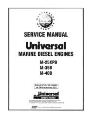
service manual 55a four marine diesel engine - Westerbeke
service manual 55a four marine diesel engine - Westerbeke
service manual 55a four marine diesel engine - Westerbeke

You also want an ePaper? Increase the reach of your titles
YUMPU automatically turns print PDFs into web optimized ePapers that Google loves.
SERVICE MANUAL<br />
55A FOUR<br />
MARINE DIESEL ENGINE<br />
PUBLICATION #43377<br />
1 st Edition / September 1998<br />
WESTCRBEKE CORPORATION· MYLES STANDISH INDUSTRIAL PARK<br />
150 JOHN HANCOCK ROAD, TAUNTON, MA 02780-7319 U.S.A.
CALIFORNIA<br />
PROPOSITION 65 WARNING<br />
Diesel <strong>engine</strong> exhaust and some<br />
of its constituents are known to<br />
the State of California to cause<br />
cancer, birth defects, and other<br />
reproductive harm.<br />
A WARNING<br />
Exhaust gasses contain Carbon Monoxide, an odorless and<br />
colorless gas. Carbon Monoxide is poisonous and can cause<br />
unconsciousness and death. Symptoms of Carbon Monoxide<br />
exposure can include:<br />
-Dizziness<br />
-Nausea<br />
-Headache<br />
- Weakness and Sleepiness<br />
- Throbbing in Temples<br />
- Muscular Twitching<br />
- Vomiting<br />
-Inability to Think Coherently<br />
IF YOU OR ANYONE ELSE EXPERIENCE ANY OF THESE SYMPTOMS,<br />
GET OUT INTO THE FRESH AIR IMMEDIATELY. «symptoms persist,<br />
seek medical attention. Shut down the unit and do not restart<br />
until it has been inspected and repaired.
SAFETY INSTRUCTIONS<br />
INTRODUCTION<br />
PREVENT BURNS -<br />
FIRE<br />
Read these safety instructions carefully. Most accidents are<br />
caused by failure to follow furuklmental rules and precautions.<br />
Know when dangerous conditions exist and take the<br />
necessary precautions to protect yourself, your personne~<br />
and your machinery.<br />
The following safety instructions are in complWnce with<br />
the American Boat and Yacht Council (ABYC) staruklrds.<br />
PREVENT ELECTRIC SHOCK<br />
A WARNING: Do not touch AC electrical connections<br />
while <strong>engine</strong> is running, or when connected to shore<br />
power. Lethal voltage is present at these connections!<br />
• Do not operate this machinery without electrical<br />
enclosures and covers in place.<br />
• Shut off electrical power before accessing electrical<br />
equipment.<br />
• Use insulated mats whenever working on electrical<br />
equipment.<br />
• Make sure your clothing and skin are dry, not damp<br />
(particularly shoes) when handling electrical equipment.<br />
• Remove wristwatch and all jewelry when working on<br />
electrical equipment.<br />
• Do not connect utility shore power to vessel's AC<br />
circuits, except through a ship-to-shore double throw<br />
transfer switch. Damage to vessel's AC generator may<br />
result if this procedure is not followed.<br />
• Electrical shock results from handling a charged capacitor.<br />
Discharge capacitor by shorting terminals together.<br />
PREVENT BURNS -<br />
HOT ENGINE<br />
A WARNING: Do not touch hot <strong>engine</strong> parts or<br />
exhaust system components. A running <strong>engine</strong> gets<br />
very hot!<br />
• Always check the <strong>engine</strong> coolant level at the coolant<br />
recovery tank.<br />
A WARNING: Steam can cause injury or death!<br />
• In case of an <strong>engine</strong> overheat, allow the <strong>engine</strong> to cool<br />
before touching the <strong>engine</strong> or checking the coolant.<br />
A WARNING: Fire can cause injury or death!<br />
• Prevent flash fires. Do not smoke or permit flames or<br />
sparks to occur near the carburetor, fuel line, filter, fuel<br />
pump, or other potential sources of spilled fuel or fuel<br />
vapors. Use a suitable container to catch all fuel when<br />
removing the fuel line, carburetor, or fuel filters.<br />
• Do not operate with a Coast Guard Approved flame<br />
arrester removed. Backfire can cause severe injury or<br />
death.<br />
• Do not operate with the air cleaner/silencer removed.<br />
Backfire can cause severe injury or death.<br />
• Do not smoke or permit flames or sparks to occur near the<br />
fuel system. Keep the compartment and the <strong>engine</strong>/generator<br />
clean and free of debris to minimize the chances of<br />
fire. Wipe up all spilled fuel and <strong>engine</strong> oil.<br />
• Be aware -<br />
PREVENT BURNS -<br />
<strong>diesel</strong> fuel will bum.<br />
EXPLOSION<br />
A WARNING: Explosions from fuel vapors can cause<br />
injury or death!<br />
• Follow re-fueling safety instructions. Keep the vessel's<br />
hatches closed when fueling. Open and ventilate cabin<br />
after fueling. Check below for fumes/vapor before running<br />
the blower. Run the blower for <strong>four</strong> minutes before<br />
starting your <strong>engine</strong>.<br />
• All fuel vapors are highly explosive. Use extreme care when<br />
handling and storing fuels. Store fuel in a well-ventilated<br />
area away from spark-producing equipment and out of<br />
the reach of children.<br />
• Do not fill the fuel tank(s) while the <strong>engine</strong> is running.<br />
• Shut off the fuel <strong>service</strong> valve at the <strong>engine</strong> when servicing<br />
the fuel system. Take care in catching any fuel that might<br />
spill. DO NOT allow any smoking, open flames, or other<br />
sources of fire near the fuel system or <strong>engine</strong> when servicing.<br />
Ensure proper ventilation exists when servicing the<br />
fuel system.<br />
• Do not alter or modify the fuel system.<br />
• Be sure all fuel supplies have a positive shutoff valve.<br />
• Be certain fuel line fittings are adequately tightened and<br />
free of leaks.<br />
• Make sure a fire extinguisher is installed nearby and is<br />
properly maintained. Be familiar with its proper use.<br />
Extinguishers rated ABC by the NFPA are appropriate<br />
for all applications encountered in this environment.<br />
Engines & Generators<br />
i
SAFETY INSTRUCTIONS<br />
ACCIDENTAL STARTING<br />
TOXIC EXHAUST GASES<br />
A WARNING: Accidental starting can cause injury<br />
Dr death!<br />
• Disconnect the battery cables before servicing the <strong>engine</strong>/<br />
generator. Remove the negative lead first and reconnect<br />
it last.<br />
• Make certain all personnel are clear of the <strong>engine</strong> before<br />
starting.<br />
• Make certain all covers, guards, and hatches are reinstalled<br />
before starting the <strong>engine</strong>.<br />
BAnERY EXPLOSION<br />
A WARNING: Battery explDsiDn can cause injury<br />
Dr death!<br />
• Do not smoke or allow an open flame near the battery<br />
being <strong>service</strong>d. Lead acid batteries emit hydrogen, a<br />
highly explosive gas, which can be ignited by electrical<br />
arcing or by lit tobacco products. Shut off all electrical<br />
equipment in the vicinity to prevent electrical arcing during<br />
servicing.<br />
• Never connect the negative (-) battery cable to the positive<br />
(+) connection terminal of the starter solenoid. Do<br />
not test the battery condition by shorting the terminals<br />
together. Sparks could ignite battery gases or fuel vapors.<br />
Ventilate any compartment containing batteries to prevent<br />
accumulation of explosive gases. To avoid sparks, do not<br />
disturb the battery charger connections while the battery<br />
is being charged.<br />
• Avoid contacting the terminals with tools, etc., to prevent<br />
burns or sparks that could cause an explosion. Remove<br />
wristwatch, rings, and any other jewelry before handling<br />
the battery.<br />
• Always turn the battery charger off before disconnecting<br />
the battery connections. Remove the negative lead first<br />
and reconnect it last when servicing the battery.<br />
BAnERYACID<br />
A WARNING: Sulphuric acid in batteries can cause<br />
severe injury Dr death!<br />
• When servicing the battery or checking the electrolyte<br />
level, wear rubber gloves, a rubber apron, and eye protection.<br />
Batteries contain sulfuric acid which is destructive. If<br />
it comes in contact with your skin, wash it off at once<br />
with water. Acid may splash on the skin or into the eyes<br />
inadvertently when removing electrolyte caps.<br />
A WARNING: CarbDn mDnDxide (CO) is a deadly gas!<br />
• Ensure that the exhaust system is adequate to expel gases<br />
discharged from the <strong>engine</strong>. Check the exhaust system<br />
regularly for leaks and make sure the exhaust manifolds<br />
are securely attached and no warping exists. Pay close<br />
attention to the manifold, water injection elbow, and<br />
exhaust pipe nipple.<br />
• Be sure the unit and its surroundings are well ventilated.<br />
• In addition to routine inspection of the exhaust system,<br />
install a carbon monoxide detector. Consult your boat<br />
builder or dealer for installation of approved detectors.<br />
• For additional information refer to ABYC T-22 (educational<br />
information on Carbon Monoxide).<br />
A WARNING: CarbDn mDnDxide (CO) is an invisible<br />
DdDrless gas. InhalatiDn prDduces flu-like symptDms,<br />
nausea Dr death!<br />
• Do not use copper tubing in <strong>diesel</strong> exhaust systems. Diesel<br />
fumes can rapidly destroy copper tubing in exhaust systems.<br />
Exhaust sulfur causes rapid deterioration of copper<br />
tubing resulting in exhaust/water leakage.<br />
• Do not install exhaust outlet where exhaust can be drawn<br />
through portholes, vents, or air conditioners. If the <strong>engine</strong><br />
exhaust discharge outlet is near the waterline, water could<br />
enter the exhaust discharge outlet and close or restrict the<br />
flow of exhaust. Avoid overloading the craft.<br />
• Although <strong>diesel</strong> <strong>engine</strong> exhaust gases are not as toxic as<br />
exhaust fumes from gasoline <strong>engine</strong>s, carbon monoxide<br />
gas is present in <strong>diesel</strong> exhaust fumes. Some of the symptoms<br />
or signs of carbon monoxide inhalation or poisoning<br />
are:<br />
Vomiting<br />
Dizziness<br />
Throbbing in temples<br />
Muscular twitching<br />
Intense headache<br />
Weakness and sleepiness<br />
AVOID MOVING PARTS<br />
A WARNING: Rotating parts can cause injury<br />
Dr death!<br />
• Do not <strong>service</strong> the <strong>engine</strong> while it is running. If a situation<br />
arises in which it is absolutely necessary to make operat-<br />
Engines & Generators<br />
ii
SAFETY INSTRUCTIONS<br />
ing adjustments, use extreme care to avoid touching<br />
moving parts and hot exhaust system components.<br />
• Do not wear loose clothing or jewelry when servicing<br />
equipment; avoid wearing loose jackets, shirts, sleeves,<br />
rings, necklaces or bracelets that could be caught in<br />
moving parts.<br />
• Make sure all attaching hardware is properly tightened.<br />
Keep protective shields and guards in their respective<br />
places at all times.<br />
• Do not check fluid levels or the drive belt's tension while<br />
the <strong>engine</strong> is operating.<br />
• Stay clear of the drive shaft and the transmission coupling<br />
when the <strong>engine</strong> is running; hair and clothing can easily<br />
be caught in these rotating parts.<br />
HAZARDOUS NOISE<br />
A WARNING: High noise levels can cause hearing<br />
loss!<br />
• Never operate an <strong>engine</strong> without its muffler installed.<br />
• Do not run an <strong>engine</strong> with the air intake (silencer)<br />
removed.<br />
• Do not run <strong>engine</strong>s for long periods with their enclosures<br />
open.<br />
ABYC, NFPA AND USCG PUBLICATIONS FOR<br />
INSTALLING DIESEL ENGINES<br />
Read the following ABYC, NFPA and USCG publications<br />
for safety codes and standards. Follow their recommendations<br />
when installing your <strong>engine</strong>.<br />
ABYC (American Boat and Yacht Council)<br />
"Safety Standards for Small Craft"<br />
Order From:<br />
ABYC<br />
3069 Solomon's Island Rd.<br />
Edgewater, MD 21037<br />
NFPA (National Fire Protection Association)<br />
"Fire Protection Standard for Motor Craft"<br />
Order From:<br />
NFPA<br />
11 Tracy Drive<br />
Avon Industrial Park<br />
Avon, MA 02322<br />
USCG (United States Coast Guard)<br />
"USCG 33CFR183"<br />
Order From:<br />
U.S. Government Printing Office<br />
Washington, D.C. 20404<br />
A WARNING: 00 not work on machinery when you<br />
are mentally or physically incapacitated by fatigue!<br />
OPERATORS MANUAL<br />
Many of the preceding safety tips and warnings are repeated<br />
in your Operators Manual along with other cautions and<br />
notes to highlight critical information. Read your <strong>manual</strong><br />
carefully, maintain your equipment, and follow all safety<br />
procedures.<br />
ENGINE INSTALLATIONS<br />
Preparations to install an <strong>engine</strong> should begin with a thorough<br />
examination of the American Boat and Yacht Council's<br />
(ABYC) standards. These standards are a combination of<br />
sources including the USCG and the NFPA.<br />
Sections of the ABYC standards of particular interest are:<br />
H-2 Ventilation<br />
P-1 Exhaust systems<br />
P-4 Inboard <strong>engine</strong>s<br />
E-9 DC Electrical systems<br />
All installations must comply with the Federal Code of<br />
Regulations (FCR).<br />
Engines & Generators<br />
iii
INSTALLATION<br />
When installing WESTERBEKE <strong>engine</strong>s and generators it is important that strict<br />
attention be paid to the following infonnation:<br />
CODES AND REGULATIONS<br />
Strict federal regulations, ABYC guidelines, and safety codes must be complied with<br />
when installing <strong>engine</strong>s and generators in a <strong>marine</strong> environment.<br />
SIPHON-BREAK<br />
For installations where the exhaust manifold/water injected exhaust elbow is close to<br />
or below the vessel's waterline, provisions must be made to install a siphon-break in<br />
the raw water supply hose to the exhaust elbow. This hose must be looped a minimum<br />
of 18" above the vessel's waterline. Failure to use a siphon-break when the exhaust<br />
manifold injection port is at or below the load waterline will result in raw water<br />
damage to the <strong>engine</strong> and possible flooding of the boat.<br />
EXHAUST SYSTEM<br />
The exhaust hose must be certified for <strong>marine</strong> use. The system must be designed to<br />
prevent water from entering the exhaust under any sea conditions and at any angle<br />
of the vessels hull.<br />
A detailed 40 page Marine Installation Manual covering gasoline and<br />
<strong>diesel</strong>, <strong>engine</strong>s and generators, is available from your WESTERBEKE<br />
dealer.<br />
Engines & Generators<br />
iv
TABLE OF CONTENTS<br />
Introduction . . . . . . . . . . . . . . . . . . . . . . . . . . . . . . . . . . . . . . . . 2<br />
55A FOUR Specifications ............................. 4<br />
Parts Identification .................................. 5<br />
Testing for Overhaul ................................. 6<br />
Engine Troubleshooting. . . . . . . . . . . . . . . . . . . . . . . . . . . . . . . 7<br />
Engine Disassembly . . . . . . . . . . . . . . . . . . . . . . . . . . . . . . . . .. 11<br />
Engine Inspection and Repair. . . . . . . . . . . . . . . . . . . . . . . . .. 16<br />
Engine Reassembly .............. :................... 26<br />
Engine Adjustments ................................. 42<br />
Glow Plugs . . . . . . . . . . . . . . . . . . . . . . . . . . . . . . . . . . . . . . . .. 51<br />
Lubrication System . . . . . . . . . . . . . . . . . . . . . . . . . . . . . . . . .. 52<br />
Remote Oil Filter (Optional) . . . . . . . . . . . . . . . . . . . . . . . . . .. 57<br />
Coolant Pump ...................................... 58<br />
Raw Water Pump ................................... 59<br />
Heat Exchanger . . . . . . . . . . . . . . . . . . . . . . . . . . . . . . . . . . . .. 60<br />
Intake/Exhaust Manifold ............................. 61<br />
Tachometer ........................................ 62<br />
Starter Motor ...................................... 63<br />
DC Electrical System/Alternator ....................... 67<br />
DC Electrical System - Wiring Diagram ................ 70<br />
DC Electrical System - Wiring Schematic .... . . . . . . . . . .. 71<br />
Transmissions ...................................... 72<br />
Service Standards ................................... 73<br />
Metric Conversions . . . . . . . . . . . . . . . . . . . . . . . . . . . . . . . . .. 77<br />
55A FOUR Torques . . . . . . . . . . . . . . . . . . . . . . .. . . . . . . . . .. 78<br />
Standard Hardware Torques, General Screws, Sealants " . .. 79<br />
Index................................. ............. 80<br />
Engines & Generators<br />
1
INTRODUCTION<br />
ENGINE OVERHAUL<br />
This <strong>service</strong> <strong>manual</strong> contains detailed information relating to<br />
the overhaul of the 55A FOUR Diesel Engine. For the major<br />
overhaul procedure, refer to the ENGINE DISASSEMBLY,<br />
ENGINE INSPECTION AND REPAIR, and ENGINE<br />
REASSEMBLY sections. Additional <strong>service</strong> information for<br />
specific components and systems may be found by referring<br />
to the Table of Contents and the Index. Refer also to your<br />
WESTERBEKE Parts Catalog.<br />
These <strong>service</strong> procedures are intended for the guidance of<br />
suitably equipped and staffed <strong>marine</strong> <strong>engine</strong> <strong>service</strong> and<br />
rebuilding facilities, and should only be undertaken by suchfacilities<br />
and their personnel.<br />
PRODUCT SOFTWARE<br />
Product software (tech data, parts lists, <strong>manual</strong>s, brochures<br />
and catalogs) provided from sources other than WESTER<br />
BEKE are not within WESTERBEKE'S control.<br />
WESTERBEKE CANNOT BE RESPONSIBLE FOR THE<br />
CONTENT OF SUCH SOFTWARE, MAKES NO WAR<br />
RANTIES OR REPRESENTATIONS WITH RESPECT<br />
THERETO, INCLUDING ACCURACY, TIMELINESS OR<br />
COMPLETENESS THEREOF AND WILL IN NO EVENT<br />
BE LIABLE FOR ANY TYPE OF DAMAGE OR INJURY<br />
INCURRED IN CONNECTION WITH OR ARISING OUT<br />
OF THE FURNISHING OR USE OF SUCH SOFTWARE.<br />
WESTERBEKE customers should also keep in mind the<br />
time span between printings of WESTERBEKE product software<br />
and the unavoidable existence of earlier WESTER<br />
BEKE <strong>manual</strong>s. Product software provided with<br />
WESTERBEKE products, whether from WESTERBEKE or<br />
other suppliers, must not and cannot be relied upon exclusively<br />
as the definitive authority on the respective product. It<br />
not only makes good sense but is imperative that appropriate<br />
representatives of WESTERBEKE or the supplier in question<br />
be consulted to determine the accuracy and currentness of the<br />
product software being consulted by the customer.<br />
NOTES, CAUTIONS AND WARNINGS<br />
As this <strong>manual</strong> takes you through the <strong>service</strong> procedures and<br />
troubleshooting of your <strong>marine</strong> <strong>engine</strong>, critical information<br />
will be highlighted by NOTES, CAUTIONS, and WARNINGS.<br />
An explanation follows:<br />
NOTE: An operating procedure essential to note.<br />
A CAUTION: Procedures. which if not strictly<br />
observed. can result in the damage or destruction of<br />
your <strong>engine</strong>.<br />
CUSTOMER IDENTIFICATION CARD<br />
1-WV-IWESIE'RBEKE<br />
I<br />
Customer Identification<br />
MR. ENGINE OWNER<br />
MAIN STREET<br />
HOMETOWN, USA<br />
Model 55A FOUR<br />
Expires 4/4/98<br />
Ser. #UOOOO-D702<br />
The WESTERBEKE <strong>engine</strong> serial number is an alphanumeric<br />
number that can assist in determining the date of manufacture<br />
of your WESTERBEKE <strong>engine</strong>. The manufacturer's<br />
date code is placed at the end of the <strong>engine</strong> serial number and<br />
consists of a character followed by three numbers. The character<br />
indicates the decade (A=1960s, B=1970s, 0=1980s,<br />
D=1990s), the first number represents the year in the decade,<br />
and the second and third numbers represent the month of<br />
manufacture.<br />
ORDERING PARTS/SERIAL NUMBER LOCATION<br />
Whenever replacement parts are needed, always provide the<br />
<strong>engine</strong> model number and <strong>engine</strong> serial number as they<br />
appear on the silver and black identification nameplate<br />
located on the side of the manifold. The <strong>engine</strong> serial number<br />
can also be found stamped into the <strong>engine</strong> block just above<br />
the injection pump.You must provide us with this information<br />
so we may properly identify your <strong>engine</strong>. In addition,<br />
include a complete part description and part number for each<br />
part needed (see the separately furnished Parts List). Also<br />
insist upon WESTERBEKE packaged parts because will fit<br />
or generic parts are frequently not made to the same specifications<br />
as original equipment.<br />
NOTE: Component locations in this <strong>manual</strong> are referenced<br />
from the front of the <strong>engine</strong> which is the pulley/drive belt end.<br />
Left and right sides are determined as follows: imagine<br />
straddling the <strong>engine</strong>, facing in the same direction as the<br />
front of the <strong>engine</strong>: the left side is at your left, the right side<br />
is at your right.<br />
Owners may find it convenient to fill in the <strong>engine</strong> identification<br />
nameplate shown below to provide a quick reference<br />
when using this <strong>service</strong> <strong>manual</strong><br />
A WARNING: Procedures, which if not properly followed.<br />
can result in personal injury or loss of life.<br />
Engines & Generators<br />
2
INTRODUCTION<br />
55A FOUR DIESEL ENGINE<br />
SPRING RETAINER<br />
INJECTION NOZZLE<br />
CYLINOER HEAD BOLT<br />
LOWER SPRING SEAT<br />
, PRE-CHAMBER<br />
t:jJ..I...-r~~~~r===d~~~~~~;;;:~~--'--- COMBUSTION<br />
CHAMBER INSERT<br />
Engines & Generators<br />
3
55A FOUR SPECIFICATIONS<br />
Engine Type<br />
Governor<br />
Valve Mechanism<br />
Combustion Chamber<br />
Bore and Stroke<br />
Piston Displacement<br />
Firing Order<br />
Direction of Rotation<br />
Maximum Torque<br />
(at 1920 rpm)<br />
Compression Ratio<br />
Compression Pressure<br />
Valve Seat Angle<br />
Valve Clearance<br />
(<strong>engine</strong> cold)<br />
Dimensions<br />
InClination<br />
Dry Weight<br />
Engine Speed<br />
Fuel Consumption<br />
Fuel<br />
Injection Pump<br />
Injection Timing<br />
Injectors<br />
Injection Pressure<br />
Lift Pump<br />
Fuel Filter (on <strong>engine</strong>)<br />
Fuel Supply and<br />
Return Piping<br />
Air Cleaner<br />
Air Flow<br />
(<strong>engine</strong> combustion)<br />
(<strong>engine</strong> cooling)<br />
Exhaust Elbow<br />
Exhaust Hose Size<br />
Muffler Size (min.)<br />
ENGINE SPECIFICATIONS<br />
Diesel, <strong>four</strong>-cycle, <strong>four</strong>-cylinder, freshwater-cooled,<br />
vertical, in-line (55 hp at<br />
3600 rpm maximum)<br />
Integral with the injection pump,<br />
mechanical centrifugal flyweight type<br />
Direct drive, OHC<br />
Swirl chamber type<br />
3.38 x 3.70 inches (86.0 x 94.0 mm)<br />
133.2 cubic inches (2.18 liters)<br />
1-3-4-2<br />
Clockwise, when viewed from the front<br />
of the <strong>engine</strong> (pulley drive belt end)<br />
931b-ft (12.9 kg-m)<br />
22.7:1<br />
426 psi (30 kg/cm2) at 200 rpm<br />
Intake 45°, Exhaust 45°<br />
Intake .008 - 0.012 in. (0.20 - 0.30mm)<br />
Exhaust 0.012-0.016 in. (0.30-0.40 mm)<br />
Height: 26.78 inches (680.2 mm)<br />
Width: 50.0 inches (546.1 mm)<br />
Length: 35.0 inches (889.0 mm)<br />
Continuous 14°; Temporary 25°<br />
(not to exceed 30')<br />
470 Ibs (213.2 kgs)<br />
Idle speed: 750 -1000 rpm<br />
Cruising speed: 2500 - 3000 rpm<br />
1.5 U.S. gph (5.6 Iph) running at 2500<br />
rpm (approximate) when the propeller<br />
allows 3600 rpm at full open throttle<br />
while underway in forward gear<br />
FUEL SYSTEM<br />
No.2 <strong>diesel</strong> oil<br />
(cetane rating of 45 or higher)<br />
Zexel mechanical governed<br />
OOTDC<br />
Throttle type<br />
1920 psi + 71 psi<br />
(135 kg/cm2 + 5 kg/cm2)<br />
12 volt - plunger type<br />
Spin-on type (replaceable)<br />
.250 in (.635 mm) 1.0. minimum<br />
.375 in (.925 mm) 1.0. maximum<br />
Replaceable paper filter element<br />
140 cfm (3.9 cmm) at 3600 rpm<br />
250 cfm (7.0 cmm)<br />
EXHAUST SYSTEM<br />
90° elbow, 45° elbow and exhaust riser<br />
2 inch 1.0. hose<br />
14 inch x 14 inch<br />
General<br />
Operating Temperature<br />
Coolant Pump<br />
Raw Water Pump<br />
COOLING SYSTEM<br />
Freshwater-cooled block, thermostatically<br />
controlled with raw water<br />
exchanger system<br />
170 - 190°F (77 - 88°C)<br />
Centrifugal type, metal impeller, beltdriven<br />
Positive displacement, rubber impeller,<br />
belt driven<br />
16.0 gpm (60.5 Ipm) approximate<br />
Raw Water Flow,<br />
at 3600 rpm<br />
(measured before discharging<br />
into exhaust elbow)<br />
Coolant System Capacity 9.5 U.S. qts (9.0 liters)<br />
Starting Battery<br />
BaHery Capacity<br />
Starter Motor<br />
Starting Aid<br />
DC No-Load Current<br />
Cold Cranking Current<br />
Alternator (standard)<br />
Regulator<br />
General<br />
Gear ratio (standard)<br />
Propell er Shaft<br />
Direction of Rotation<br />
Propeller<br />
Recommendations<br />
(using standard<br />
transmission<br />
2.74:1 reduction)<br />
Lubricating Fluid<br />
Transmission Sump<br />
Oil Pump<br />
Oil Filter<br />
Lube Oil Cooler<br />
Lubricant Capacity<br />
Sump Capacity<br />
Operating Oil Pressure<br />
Oil Grade<br />
ELECTRICAL SYSTEM<br />
12-volt DC, (-) negative ground<br />
300 - 400 Cold cranking amps (CCA)<br />
(min.)<br />
12-volt, 1.6kw, SOlenoid, actuated shift<br />
reduction gear<br />
12 volt sheathed type glow plug<br />
100 amps at 11.5 volts (3000 rpm,<br />
min.)<br />
280 - 300 amps at 10 volts (250 rpm,<br />
min.)<br />
12-volt, DC, 50 amps<br />
Internal regulator, built into alternator<br />
TRANSMISSION<br />
(Hurth Standard Transmission) Casehardened<br />
helical gears, with a servooperated<br />
multiple disc clutch.<br />
2.74: 1 (HBW250 - 3R)<br />
Right handed - standard transmission<br />
20 D x 13 P - 2 blade or 200 x 11 P - 3<br />
blade propeller should allow the <strong>engine</strong><br />
to reach its full rated rpm (3600 + 000<br />
- 100) at full open throttle while underway<br />
in forward gear.<br />
ATF- type A or Dextron -/I or 11/<br />
0.79 U.S. qts (0.75 liters) approximate<br />
Crescent type directly driven by the.<br />
crankshaft.<br />
Full flow, paper element, spin-on type<br />
Fresh water cooled.<br />
1.75 U.S. gal. (6.6. liters)<br />
5.0 U.S. qts (4.8 liters) not including filter<br />
30 - 60 psi (2.1 - 4.2 kg/cm2) at maximum<br />
<strong>engine</strong> rpm and at normal operating<br />
temperature<br />
API Specification CF or CG-4,<br />
SAE 30, 10W-30, 15W-40<br />
Engines & Generators<br />
4
PARTS IDENTIFICATION<br />
ANODE<br />
WATER 'I'M""",UI<br />
SENDER<br />
LUBE OIL DRAIN HOSE<br />
FRONT<br />
OIL PRESSURE SENDER STARTER WITH SOLENOID<br />
LEFT SIDE<br />
REAR<br />
BATTERY GROUND CONNECTION<br />
UNIT I. D. PLATE<br />
AIR CLEANER HOUSING<br />
MANIFOLD PRESSURE CAP<br />
DOMESTIC<br />
WATER HEATER<br />
CONNECTION POINTS<br />
RAW WATER PUMP<br />
TRANSMISSION<br />
SHIFT LEVER<br />
LUBE OIL FILTER<br />
REAR<br />
RIGHT SIDE<br />
'"<br />
A<br />
FRONT<br />
OIL COOLER<br />
Engines & Generators<br />
5
TESTING FOR OVERHAUL<br />
HOW TO DETERMINE WHEN<br />
TO OVERHAUL THE ENGINE<br />
Cause of Low Compression<br />
Generally, the time at which an <strong>engine</strong> should be overhauled<br />
is determined by various conditions such as lowered <strong>engine</strong><br />
power output, decreased compression pressure, and increased<br />
fuel and oil consumption. The lowered <strong>engine</strong> power output,<br />
in the case of <strong>diesel</strong> <strong>engine</strong>s, is not necessarily due to trouble<br />
with the <strong>engine</strong> itself, but is sometimes caused by injector<br />
nozzle wear or injection pump wear. It is most reasonable to<br />
judge by a decrease in compression pressure. The decrease in<br />
compression pressure is caused by many factors. Itis, therefore,<br />
necessary to determine a cause or causes on the basis of<br />
data produced by periodic inspection and maintenance. Oil<br />
analysis on a seasonal basis is a good means of monitoring<br />
<strong>engine</strong> internal wear. When caused by worn cylinders or piston<br />
rings, the following symptoms will occur:<br />
• Low <strong>engine</strong> power output<br />
• Increased fuel consumption<br />
• Increased oil consumption<br />
• Hard <strong>engine</strong> starting<br />
• Noisy <strong>engine</strong> operation<br />
These symptoms often appear together. Increased fuel consumption<br />
and hard <strong>engine</strong> starting can result also from excessive<br />
fuel injection, improper injection timing, and wear of<br />
plugs and nozzles. They are caused also by defective electrical<br />
devices such as the battery, alternator, starter and glow<br />
plugs. Therefore it is desirable to judge the optimum <strong>engine</strong><br />
overhaul time by the lowered compression pressure caused<br />
by worn cylinders and pistons plus increased oil consumption.<br />
In <strong>diesel</strong> <strong>engine</strong>s, satisfactory combustion is obtained<br />
only under sufficient compression pressure. If an <strong>engine</strong><br />
lacks compression pressure, incomplete combustion of fuel<br />
will take place even if other parts of the <strong>engine</strong> are operating<br />
properly. To determine the period of <strong>engine</strong> overhaul, it is<br />
important to measure the <strong>engine</strong> compression pressure regularly.<br />
At the same time, the <strong>engine</strong> speed at which the measurement<br />
of compression pressure is made should be checked<br />
because the compression pressure varies with <strong>engine</strong> rpm.<br />
The <strong>engine</strong> rpm can be measured at the front end of the<br />
crankshaft.<br />
Measuring Compression Pressure<br />
NOTE: Do not guess the conditions of other cylinders from a<br />
result of testing one cylinder. Be sure to measure the compression<br />
pressure for each cylinder. Look for cylinders with<br />
dramatically (at least 20%) lower compression than the average<br />
of the other cylinders. If the weak cylinder is flanked by<br />
healthy cylinders, the problem is either valve- or head-gasket<br />
related. Very low compression in an adjacent cylinder indicates<br />
gasket failure. Abnormally high readings on all cylinders<br />
indicate heavy carbon accumulations, a condition that<br />
might be accompanied by high pressures and noise.<br />
NOTE: In case of severe vibrations and detonation noise,<br />
have the injectors overhauled by an authorizedJueI injection<br />
<strong>service</strong> center. Poor fuel quality, contaminates, and loss of<br />
positive fuel pressure to the injection pump will result in<br />
injector faults.<br />
OVERHAUL CONDITIONS<br />
Compression pressure tends to increase a little in a new<br />
<strong>engine</strong> until the piston rings and valve seats have been broken<br />
in. Thereafter, it decreases gradually with the progressive<br />
wear of these parts. Engine compression should be 30 kg/cm2<br />
(at 200 rpm).<br />
When the decrease of compression pressure reaches its limit<br />
(see SERVICE STANDARDS), the <strong>engine</strong> must be overhauled.<br />
The <strong>engine</strong> also requires an overhaul when oil consumption<br />
is high, when blowby is evident, and when<br />
compression values are at minimum or below.<br />
NOTE: Refer to the SERVICE STANDARDS chart during an<br />
<strong>engine</strong> overhaul. It gives the measurements and values for<br />
the repair or replacement of the <strong>engine</strong> components.<br />
To check the compression pressure, see COMPRESSION<br />
TEST under ENGINE ADJUSTMENTS.<br />
Engines & Generators<br />
6
ENGINE TROUBLESHOOTING<br />
The following troubleshooting table describes certain<br />
problems relating to <strong>engine</strong> <strong>service</strong>, the probable causes of<br />
these problems, and the recommendations to overcome<br />
these problems.<br />
Note: The <strong>engine</strong>'s electrical system is protected by a 20-<br />
ampere <strong>manual</strong> reset circuit breaker. The preheat solenoid is<br />
mounted on the same bracket.<br />
PROBLEM PROBABLE CAUSE VERIFICATION/REMEDY<br />
HARD STARTING<br />
LOW CRANKING SPEED<br />
1. Engine oil viscosity too high. 1. Replace <strong>engine</strong> oil with less viscous oil.<br />
2. Run-down battery. 2. Recharge battery.<br />
3. Worn battery. 3. Replace battery.<br />
4. Battery terminals loosely connected. 4. Clean terminals and correct cables.<br />
5. Defective starter. 5. Repair or replace starter.<br />
6. Defective main drive section. 6. Check clutch for disengagement.<br />
DEFECTIVE INJECTION SYSTEM<br />
1. Air trapped in fuel passage. 1. Bleed air from fuel system.<br />
2. Clogged fuel filter. 2. Clean or replace filter.<br />
3. Low injection pressure. 3. Adjust injection pressure.<br />
4. Inadequate spray. 4. Clean or replace nozzle.<br />
5. Injection pump delivering insufficient fuel. 5. Repair or replace injection pump.<br />
6. Injection too early. 6. Adjust injection timing.<br />
ENGINE TROUBLES<br />
1. Low compression.<br />
a. Incorrect valve clearance. a. Adjust valve clearance.<br />
b. Inadequate contact of valve seat. b. Lap valve.<br />
c. Valve stem seized. c. Replace valve and valve guide.<br />
d. Broken valve spring. d. Replace valve spring.<br />
e. Compression leaks through cylinder head gasket. e. Replace gasket.<br />
I. Cracked or distorted cylinder head. I. Replace cylinder head.<br />
g. Piston ring seized. g. Replace piston and piston ring.<br />
h. Worn piston ring and cylinder. h. Overhaul <strong>engine</strong>.<br />
i. Cracked or wom piston. i. Replace piston.<br />
2. Burnt glow plug. 2. Replace glow plug.<br />
3. Faulty glow plug operation. 3. Check glow plugs and solenoid.<br />
4. Incorrect governor lever pOSition. 4. Set lever to starting position.<br />
5. Governor spring out of position. 5. Correct spring.<br />
POOR IDLING 1. I mproper valve clearance. 1. Adjust valve clearance.<br />
2. Poor valve to valve seat contact. 2. Repair or replace.<br />
3. Failure of cylinder head gasket. 3. Replace gasket.<br />
4. Malfunction of fuel system. 4. See LOW OUTPUT and ROUGH OPERATION.<br />
LDW OUTPUT LOW COMPRESSION See Low Compression under HARD STARTING.<br />
INJECTION SYSTEM OUT OF ADJUSTMENT<br />
1. Incorrect injection timing. 1. Adjust injection timing.<br />
2. Insufficient injection. 2. Repair or replace injection pump.<br />
3. Low injection pressure. 3. Check injection nozzle and adjust pressure.<br />
INSUFFICIENT FUEL<br />
1. Air trapped in fuel system. 1. Check and retighten connector.<br />
2. Clogged filter. 2. Clean or replace filter.<br />
3. Contaminated fuel tank. 3. Clean tank.<br />
INSUFFICIENT INTAKE AIR<br />
1. Clogged air cleaner. 1. Clean or replace air cleaner.<br />
(continued)<br />
Engines & Generators<br />
7
ENGINE TROUBLESHOOTING<br />
PROBLEM PROBABLE CAUSE VERIFICATION/REMEDY<br />
LOW OUTPUT (cont.)<br />
OVERHEATING<br />
1. Low coolant level. 1. Add coolant.<br />
2. Loose V-belt. 2. Adjust or replace V-belt.<br />
3. Incorrect injection timing. 3. Adjust injection timing.<br />
4. Low <strong>engine</strong> oil level. 4. Add <strong>engine</strong> oil.<br />
EXCESSIVE OIL<br />
OIL LEAKAGE<br />
CONSUMPTION 1. Defective oil seals. 1. Replace oil seals.<br />
2. Loose oil filter. 2. Tighten.<br />
3. Broken cylinder head cover gasket. 3. Replace gasket.<br />
4. Damaged cylinder head cover. 4. Replace.<br />
5. Damaged front housing gasket. 5. Replace.<br />
6. Loose oil pipe connector. 6. Retighten oil connections.<br />
7. Loose bolt(s) at oil pump body, cylinder head 7. Tighten.<br />
covers or oil pan.<br />
8. Loose or damaged oil pressure switch. 8. Tighten or replace.<br />
9. Defective seal at oil pan and cylinder block. 9. Repair.<br />
10. Loose drain plug. 10. Retighten or replace.<br />
OIL LEVEL RISING<br />
1. Incorrectly positioned piston ring gaps. 1. Correct ring gap positions.<br />
2. Displaced or twisted connecting rod. 2. Replace connecting rod.<br />
3. Worn piston ring. 3. Replace ring.<br />
4. Worn piston or cylinder. 4. Replace piston and rebore cylinder.<br />
OIL LEVEL FALLING<br />
1. Defective stem seal. 1. Replace stem seal.<br />
2. Worn valve and valve guide. 2. Replace valve and valve guide.<br />
OIL PRESSURE DROP 1. Oil leak. 1. See OIL LEAKAGE<br />
2. Insufficient oil. 2. Add oil.<br />
3. Worn and/or damaged oil pump gear. 3. Replace.<br />
4. Worn oil pump plunger or weak spring. 4. Replace.<br />
5. Clogged oil strainer. 5. Clean.<br />
6. Excessive lubrication clearance between main 6. See Crankshaft Assembly under<br />
bearing and connecting rod bearing.<br />
ENGINE REASSEMBLY.<br />
EXCESSIVE FUEL<br />
ENGINE BODY TROUBLES<br />
CONSUMPTION 1. Noisy knocking. 1. See KNOCKING.<br />
2. Smoky exhaust. 2. See SMOKY EXHAUST.<br />
3. Moving parts nearly seized or excessively worn. 3. Repair or replace.<br />
4. Poor compression. 4. See Low compression under HARD STARTING.<br />
5. Improper valve timing. 5. Adjust.<br />
6. Improper valve clearance. 6. Adjust.<br />
SMOKY EXHAUST<br />
INSUFFICIENT INTAKE AIR<br />
1. Air intake obstructed. 1. Clean and remove obstruction.<br />
NOZZLE TROUBLES<br />
1. Seized nozzle. 1. Replace.<br />
2. Worn nozzle. 2. Replace.<br />
IMPROPER FUEL<br />
FUEL LEAKS<br />
Replace with proper fuel.<br />
Find fuel leaks.<br />
WHITISH OR PURPLISH<br />
1. Excessive <strong>engine</strong> oil. 1. Correct oil level.<br />
2. Excessive rise of oil into combustion chamber.<br />
a. Poor piston contact. a. Check.<br />
b. Seized piston ring. b. Replace or clean.<br />
c. Excessive piston-to-cylinder clearance. c. Replace or correct.<br />
Engines & Generators<br />
8<br />
(continued)
ENGINE TROUBLESHOOTING<br />
PROBLEM PROBABLE CAUSE VERIFICATION/REMEDY<br />
SMOKY EXHAUST (cont.)<br />
WHITISH OR PURPLISH (cont.)<br />
d. Worn valve stem and valve guide. d. Replace.<br />
e. Low <strong>engine</strong> oil viscosity. e. Replace.<br />
f. Excessive oil pressure. f. Correct.<br />
3. Injection timing is too late. 3. Adjust.<br />
4. Insufficient compression. 4. See Low compression under HARD STARTING.<br />
BLACKISH OR DARK GRAYISH<br />
1. Engine body troubles.<br />
a. Poor compression. a. See Low compression under HARD STARTING.<br />
b. Improper valve clearance. b. Adjust.<br />
2. Insufficient intake air (air cleaner clogged). 2. Clean air cleaner.<br />
3. Improper fuel. 3. Replace with proper fuel.<br />
ABNORMAL SOUND CRANKSHAFT AND MAIN BEARING<br />
OR NOISE 1. Main bearing worn, heat-damaged or seized. 1. Replace bearing and grind crankshaft.<br />
2. Excessive main bearing oil clearance. 2. Replace bearing.<br />
3. Melted main bearing. 3. Replace bearing and check lubrication system.<br />
4. Badly worn crankshaft. 4. Grind crankshaft.<br />
5. Excessive crankshaft end play. 5. Adjust end play.<br />
CONNECTING ROD AND CONNECTING ROD BEARING<br />
1. Connecting rod big end bearing worn, 1. Replace bearing.<br />
heat-damaged or seized.<br />
2. Worn crankpin. 2. Grind crankshaft.<br />
3. Bent connecting rod. 3. Correct bend or replace.<br />
PISTON, PISTON PIN, AND PISTON RING<br />
1. Worn cylinder. 1. Rebore cylinder to oversize and replace piston.<br />
2. Worn piston or piston pin. 2. Replace piston.<br />
3. Piston seized. 3. Replace piston and rebore cylinder.<br />
4. Piston seized and rings worn or damaged. 4. Replace piston and rings.<br />
5. Bent connecting rod. 5. Replace connecting rod.<br />
VALVE MECHANISM<br />
1. Worn camshaft. 1. Replace camshaft.<br />
2. Excessive valve clearance. 2. Adjust valve clearance.<br />
3. Broken valve spring. 3. Replace valve spring.<br />
4. Worn timing gear. 4. Replace timing gear.<br />
OTHER<br />
1. Fresh water pump bearing malfunction. 1. Replace bearing.<br />
2. Incorrect drive belt tension. 2. Adjust.<br />
3. Alternator bearing malfunction. 3. Replace bearing.<br />
4. Exhaust gas leakage. 4. Repair.<br />
5. Timing belt tensioner malfunction. 5. Replace tensioner.<br />
ROUGH OPERATION INJECTION PUMP SYSTEM<br />
(HUNTING) 1. Uneven injection. 1. Adjust injection or replace parts.<br />
2. Control rack malfunctioning. 2. Disassemble, check and correct injection pump.<br />
3. Worn delivery valve. 3. Replace delivery valve.<br />
4. Inadequate injection nozzle spray. 4. Replace injection nozzle.<br />
GOVERNING SYSTEM<br />
1. Governor lever malfunctioning. 1. Check governor shaft and correct operation.<br />
2. Fatigued governor spring. 2. Replace spring.<br />
(continued)<br />
Engines & Generators<br />
9
ENGINE TROUBLESHOOTING<br />
KNOCKING<br />
PROBLEM PROBABLE CAUSE VERIFICATIONJREMEDY<br />
ENGINE KNOCKS WITHOUT MUCH SMOKE<br />
1. Engine troubles.<br />
8. Overheated cylinder. 8. See OVERHEATING; LOW OUTPUT.<br />
b. Carbon deposits in cylinder. b. Clean.<br />
2. Too early injection timing. 2. Correct.<br />
3. Too high injection pressure. 3. Correct.<br />
4. Improper fuel. 4. Replace with proper fuel.<br />
KNOCKING WITH DARK SMOKE<br />
1. Poor compression. 1. See Low compression under HARD STARTING.<br />
2. Injection pump malfunctioning.<br />
8. Worn plunger. 8. Replace.<br />
b. Pinion is not in mesh with control rack. b. Correct.<br />
c. Broken delivery valve spring. c. Replace.<br />
d. Worn delivery valve seat. d. Replace.<br />
3. Improper nozzle.<br />
8. Poor spray. 8. Clean or replace nozzle.<br />
b. Poor chattering. b. Repair or replace nozzle.<br />
c. After-injection drip. c. Repair or replace nozzle.<br />
d. Nozzle needle valve seized. d. Replace.<br />
INTERMITTENT 1. Fuel filter clogged. 1. Clean or replace.<br />
EXHAUST SOUND 2. Fuel pipe sucks air. 2. Retighten pipe joints or replace pipe.<br />
3. Water mixed in fuel 3. Replace fuel.<br />
OVERHEATING 1. V-belt slackening or slippery with oil. 1. Adjust, replace or clean.<br />
2. Damaged water pump. 2. Replace.<br />
3. Lack of coolant. 3. Add.<br />
4. Low oil level or poor oil quality. 4. Add or change.<br />
5. Knocking. 5. See KNOCKING.<br />
6. Moving parts seized or damaged. 6. Replace.<br />
Engines & Generators<br />
10
ENGINE DISASSEMBLY<br />
NOTE: Before disassembly and cleaning, carefully check<br />
for defects which cannot be found after disassembly and<br />
cleaning.<br />
GENERAL DISASSEMBLY PROCEDURE<br />
• All disassembled parts should be carefully arranged in<br />
the order of reassembly. Mark or label the parts as<br />
needed to insure proper mating and reassembly in the<br />
proper directions and positions.<br />
• If the disassembly procedure is complex requiring many<br />
parts to be disassembled, the parts should be disassembled<br />
in a way that will allow them to be efficiently<br />
reassembled without any change in the <strong>engine</strong>'s external<br />
appearance or its performance.<br />
• Do not remove or disassemble parts that require no disassembly.<br />
• Carefully inspect each part after removal for damage,<br />
4eformation, and other problems.<br />
• Be careful not to damage the disassembled parts. Keep<br />
the parts clean.<br />
• Use the proper tools. Apply oil when necessary. Take<br />
special care to keep the fuel system parts free from the<br />
intrusion of dust and dirt.<br />
• Remove the transmission first, then disassemble the<br />
<strong>engine</strong>.<br />
TRANSMISSION REMOVAL<br />
1. Unplug the instrument panel wiring harness.<br />
2. Drain the transmission fluid and the transmissin oil<br />
cooler hoses<br />
3. Detach the oil cooler hoses.<br />
4. Unbolt the transmission from the <strong>engine</strong>.<br />
NOTE: For transmission <strong>service</strong> and maintenance, refer to<br />
your transmission owner~ <strong>manual</strong>. To rebuild a transmission,<br />
contact your WESTERBEKE dealer or a qualified<br />
<strong>marine</strong> transmission <strong>service</strong> facility.<br />
ENGINE DISASSEMBLY<br />
1. Clean the exterior of the <strong>engine</strong> of any deposits of dirt<br />
and oil.<br />
2. Mount the <strong>engine</strong> on a suitable <strong>engine</strong> stand for disassembly.<br />
3. Drain the coolant from the <strong>engine</strong> and the heat<br />
exchanger. Drain the fuel and the <strong>engine</strong> oil.<br />
4. Remove the <strong>engine</strong> wiring harness in its entirety. Label<br />
the terminal connections to insure proper reattachment.<br />
5. Remove the <strong>engine</strong> heat exchanger and the <strong>engine</strong> oil<br />
cooler/oil filter assembly. If possible, leave one end of<br />
each hose connection attached to the part being removed.<br />
6. Remove the starter motor.<br />
7. Remove the <strong>engine</strong> bellhousing.<br />
8. Remove the transmission damper plate.<br />
9. Remove the flywheel.<br />
10. Remove the <strong>engine</strong> back plate.<br />
11. Unclamp the exhaust elbow, the two coolant hoses on the<br />
exhaust manifold, and the coolant recovery tank hose,<br />
then remove the intake/exhaust manifold in its entirety<br />
with its <strong>four</strong> gaskets.<br />
EXHAUST<br />
ELBOW<br />
12. Remove the alternator.<br />
13. Remove the raw water pump.<br />
COOLANT<br />
RECOVERY<br />
TANK<br />
. INTAKEJEXHAUST<br />
MANIFOLD<br />
14. Remove the <strong>engine</strong> mounted fuel filter and the fuel line<br />
to the injection pump. (Note the arrangement of the seal- .<br />
ing washers on the banjo bolts at the fuel filter and the<br />
injection pump). Remove the fuel lift pump.<br />
15. Remove the thermostat housing, gasket, and the thermostat.<br />
Leave the temperature sending unit in place.<br />
Engines & Generators<br />
11
ENGINE DISASSEMBLY<br />
16. Remove the idler pulley bracket and idler pulley.<br />
17. Remove the seal plate.<br />
18. Remove the coolant pump.<br />
19. Remove all the high pressure injector lines from the<br />
injection pump to the injectors. Leave the two upper line<br />
clamps in place.<br />
NOTE: Cap the ends of the lines, and the connections at<br />
the injection pump and at the injectors, to prevent entry<br />
of foreign material.<br />
20. Remove the fuel return lines from the top of the injectors<br />
and from the fuel injection pump. (Note the washer arrangement<br />
on the fuel return line banjo bolts. Cap all openings<br />
on the fuel return line, injectors and injection pump.)<br />
21. Remove the fuel injectors, dust seals and sealing washers<br />
from the cylinder head.<br />
22. Remove the glow plugs.<br />
23. Remove the cylinder head cover.<br />
24. Fuel Injection Pump.<br />
NOTE: The fuel injection pump is a very important component<br />
of the <strong>diesel</strong> <strong>engine</strong>, requiring the utmost care in<br />
handling. It has been thorol,tghly bench-tested, and the<br />
owner/operator is cautioned not to attempt to <strong>service</strong> it. If<br />
the fuel injection pump requires servicing, remove it and<br />
take it to an authorized fuel injection pump <strong>service</strong><br />
facility. Do not attempt to disassemble and repair it. If<br />
the pump is defective, WESTERBEKE recommends that<br />
you replace the entire pump.<br />
The only adjustment the servicing mechanic should<br />
make to the fuel injection pump is the adjustment for<br />
<strong>engine</strong> idle speed (see IDLE SPEED ADJUSTMENT<br />
under ENGINE ADJUSTMENTS).<br />
Fua INJECTION PUMP<br />
Remove the injection pump as follows:<br />
NOTE: Scribe mating I -:..:" ~<br />
marks on the pump body / ~<br />
flange and the timing belt<br />
cover before removal.<br />
MATING<br />
MARKS<br />
3. Remove the two timing belt covers.<br />
b. Loosen the two injection pump hold-down nuts. Do<br />
not remove them entirely. The hold-down nut on the<br />
<strong>engine</strong> side of the pump can be loosened by using a<br />
1/4" universal socket and extension with a ratchet.<br />
c. Remove the nut and lockwasher from the injection<br />
pump shaft.<br />
d. Place the keyway on the injection pump shaft in the 12<br />
o'clock position using the front crankshaft pulley bolt<br />
before attempting to remove the injection pump.<br />
e. Using the puDey puDer (49 S120 215A), apply sufficient<br />
pressure to loosen the pump from the pulley. The<br />
loose hold down nuts will prevent the pump from<br />
falling from the <strong>engine</strong>.<br />
NOTE: If an extractor is not available, replace the nut<br />
loosely on the injection pump shaft, and with a nylon<br />
drift and hammer, gently tap the injection pump shaft<br />
to dislodge it from the keyed pulley.<br />
INJECTION<br />
PUMP PULLEY<br />
;:r~~ffl~I---- PULLEY PULLER<br />
.49 S120 215A<br />
f. Once loosened, remove the hold down nuts and washers<br />
and carefully withdraw the pump from the pulley<br />
and the <strong>engine</strong>.<br />
25. Remove the following components:<br />
3. Oil pressure switch and oil level gauge.<br />
b. Dipstick tube.<br />
c. Cylinder head cover.<br />
d. Crankshaft pulley.<br />
e. Oil strainer and oil pan.<br />
f. Oil pump assembly.<br />
g. Rear cover.<br />
h. Connecting rod caps.<br />
i<br />
Pistons and connecting rods.<br />
j. Piston rings.<br />
k. Main bearing caps.<br />
L Main bearings.<br />
m.Oiljets.<br />
D. Crankshaft.<br />
Engines & Generators<br />
12
ENGINE DISASSEMBLY<br />
nming Belt<br />
NOTE: WESTERBEKE recommends replacing the timing<br />
belt during an <strong>engine</strong> overhaul. Timing belt failure could<br />
result in major damage to the <strong>engine</strong>.<br />
NOTE: If the tming belt is to be reused, draw an arrow on<br />
the belt pointing in the direction of the belt's rotation so it<br />
will be replaced in the same direction.<br />
TIMING MARK<br />
DIRECTION ARROW ___ ''--01<br />
CRANKSHAFT<br />
TIMING<br />
BELT<br />
1. Loosen the timing belt tensioner lock bolt, push the timing<br />
belt tensioner left as far as it will go, then temporarily<br />
retighten the lock bolt.<br />
Injection Pump Pulley<br />
1. Put two bolts (size M8 x 1.25 x 35 - 40 mm) through the<br />
arms of the injection pump pulley and insert them in the<br />
thread hole of the injection pump bracket.<br />
NOTE: This is to prevent the injection pump pulley from<br />
turning while loosening the injection pump pulley lock bolt.<br />
2. Loosen the injection pump pulley lock bolt.<br />
2. Remove the timing belt.<br />
3. Remove the timing belt tensioner.<br />
4. Tum the crankshaft clockwise about 45° from the timing<br />
mark which is marked on the oil pump housing.<br />
NOTE: Turning the crankshaft prevents the pistons and<br />
valves from contacting one another.<br />
3. Using the pulley puller (49 S120 215A), separate the<br />
injection pump pulley from the injection pump shaft.<br />
INJECTION<br />
PUMPPULLE"t.<br />
~~n~~,-__ PULLEY PULLER<br />
~ 49 S120 215A<br />
Engines & Generators<br />
13
ENGINE DISASSEMBLY<br />
Camshaft Pulley & Timing Belt Pulley<br />
1. Hold the camshaft with a wrench (29 mm, 1.1 in) and<br />
loosen the camshaft pulley lock bolt.<br />
Cylinder Head Bolts<br />
1. Loosen the cylinder head bolts in the numbered sequence<br />
shown in the ilustration. Loosen them a little at a time, in<br />
sequence.<br />
1 3 5 4 2<br />
CAMSHAFT<br />
PULLEY<br />
LOCK BOLT--4I.IZ<br />
CYLINDER HEAD BOLTS<br />
Cylinder Head and Gasket<br />
A CAUTION: Do not damage the edge of the<br />
cylinder head with the wrench. If it is damaged,<br />
<strong>engine</strong> oil may leak.<br />
A CAUTION: Before removing the camshaft pulley,<br />
turn the crankshaft 45" clockwise to prevent<br />
damage to the valves.<br />
2. Remove the camshaft pulley from the camshaft using the<br />
same procedure described under Injection Pump Pulley,<br />
above.<br />
1. Remove the cylinder head by tapping it with a plastic<br />
hammer.<br />
2. Remove the cylinder head gasket.<br />
Camshaft<br />
1. Gradually loosen the camshaft cap nuts in the numbered<br />
sequence shown in the illustration.<br />
2. Remove the caps.<br />
3. Remove the camshaft and oil seals.<br />
3 7 10 6<br />
2<br />
A CAUTION: Do not hit the camshaft pulley with<br />
a hammer.<br />
CAMSHAFT PULLEY<br />
4 8 9 5·<br />
LOOSENING THE CAMSHAFT CAP NUTS<br />
1<br />
Adjusting Discs and Tappets<br />
1. Remove the adjusting discs and tappets as a set.<br />
A CAUTION: All adi~ing discs and tappets<br />
should be disassembled in a way that-COllect<br />
reassembly can be performed efficiently.<br />
3. Remove the timing belt pulley.<br />
Engines & Generators<br />
14
ENGINE DISASSEMBLY<br />
Valve Seals<br />
0000000<br />
ADJUSTING DISCS AND TAPPETS<br />
1. Move the piston of the valve seal to be replaced to<br />
approximately top dead center.<br />
2. After removing the lower spring seats, remove the valve<br />
seals by using the valve seal remover (49 S120 170) to<br />
grasp and work them out.<br />
NOTE: The valve seal remover (49 S120 170) cannot<br />
grasp the valve seals unless the lower spring seats have<br />
been removed.<br />
Valves<br />
1. Remove the springs.<br />
2. Remove the valves, lower spring seats and spring retainers<br />
from the cylinder head by using an appropriate valve<br />
spring compression tool.<br />
VALVE SEAL<br />
REMOVER<br />
49 S120 170<br />
VALVE SPRING LIFTER·<br />
490636100A<br />
Combustion Chamber Inserts<br />
1. Remove the combustion chamber inserts from the bottom<br />
surface of the cylinder head by using a suitable mandrel.<br />
PIVOT<br />
·49 S120 222<br />
NOTE: The valve guides are to be removed only after measuring<br />
the valve guide/valve stem (see Valve Guides under<br />
ENGINE INSPECTION.<br />
Engines & Generators<br />
15
ENGINE INSPECTION AND REPAIR<br />
GENERAL INSPECTION PROCEDURE<br />
1. Before inspection, clean each part taking care to remove<br />
any gasket fragments, dirt, oil or grease, carbon, moisture<br />
residue, or other foreign materials.<br />
2. Be careful not to damage the joints or sliding parts of<br />
aluminum alloy components such as the cylinder head<br />
and the pistons.<br />
3. Inspection and repair should be done in the order indicated.<br />
ENGINE INSPECTION<br />
Cylinder Head<br />
1. Inspect for water leakage, fuel leakage, damage, and<br />
cracks. If a problem is found, replace the part.<br />
2. Measure the cylinder head for distortion in six directions<br />
using a thickness gauge, as shown in the illustrations.<br />
Distortion limit: 0.10 mm (0.004 in)<br />
4. Measure the manifold contact surface distortion in the<br />
three directions shown in the illustration. If the distortion<br />
exceeds the limit, grind the surface, or replace the cylinder<br />
head.<br />
Distortion limit: 0.20 mm (0.008 in)<br />
MANIFDLD CONTACT SURFACE DISTORTION<br />
5. Measure the oil clearance of the camshaft.<br />
a. Remove the tappets and adjusting discs from the cylinder<br />
head, and separate them by cylinder.<br />
CYUNDER HEAD DISTDRTIDN<br />
STRAIGHTEDGE<br />
000 00·0 0<br />
TAPPETS AND ADJUSTING DISCS REMOVAL<br />
b. Clean away oil and dirt from the camshaft and cylinder<br />
head journals.<br />
c. Set a plastigauge on the camshaft journal (in the axial<br />
direction of the journal).<br />
d. Set the camshaft caps, and tighten the nuts to the specified<br />
torque.<br />
CYUNDER HEAD DISTDRTIDN j<br />
3. If cylinder head distortion exceeds the limit, replace the<br />
cylinder head.<br />
A CAUTION: Do not attempt to repair the cylinder<br />
head by milling or grinding. Handle the cylinder<br />
head carefully, taking special care not to damage<br />
its lower surface.<br />
. . CAMSHAFT CAPS<br />
Camshaft cap nut tightening torque:<br />
2.0 - 2.7 kg-m (15 - 20 ft-Ib)<br />
Engines & Generators<br />
16
ENGINE INSPECTION AND REPAIR<br />
A CAUTION: When installing the camshaft<br />
caps, note the correct sequence and the a"ow<br />
maries. When tightening the camshaft cap nuts,<br />
do so evenly and in the sequence shown in the<br />
illustration.<br />
10 6 2 : 3<br />
7<br />
MEASURING THE CAMSHAFT END PLAY!<br />
9 5 1 4<br />
TIGHTENING THE CAMSHAFT CAP NUTS<br />
- .<br />
e. Remove'the camshaft caps and measure the oil clearance.<br />
Standard oil clearance:<br />
- O~025 - 0.066 mil! «()'~098 - 0-9260 in)<br />
limit: 0.1 mm (0.0039 in)<br />
f. If the oil clearance exceeds the limit, replace the<br />
cylinder head or the camshaft.<br />
-----~<br />
8<br />
7. Measure the amount that the combustion chamber insert<br />
has receded.<br />
a. Clean the lower side so that the surface of the combustion<br />
chamber insert won't be scarred.<br />
h. Measure using a dial gauge.<br />
limits:<br />
Receded amount: 0.04 mm (0.0016 in)<br />
Projection amount: 0.05 mm (0.0024 in)<br />
c. If either limit is exceeded, replace the combustion<br />
chamber insert or the cylinder head.<br />
COMBUSTION<br />
CHAMBER INSERT<br />
• MEASURING THE DlL CLEARANCE<br />
6. Measure the end play of the camshaft. If the end play<br />
exceeds the limit, replace the camshaft or the cylinder<br />
head. .<br />
Standard camshaft end play:<br />
0.02 - 0.15 mm (0.00079 - 0.00591 in)<br />
limit: 0.2 mm (0.0079 in)<br />
Valve Seats<br />
1. Use a thickness guage and a straightedge, as shown in the<br />
illustration, to measure the amount the valve has receded<br />
from the cylinder head surface.<br />
Engines & Generators<br />
17
ENGINE INSPECTION AND REPAIR<br />
If the receded amount is 1.55 - 2.55 mm (0.061 - 0.100<br />
in), use an equivalent washer at the valve spring seat. If<br />
the receded amount is 2.55 mm (0.100 in) or more,<br />
replace the cylinder head<br />
Standard amount of valve recession<br />
Intake and exhaust (cold <strong>engine</strong>):<br />
0.75 -1.05 mm (0.030 - 0.041 in)<br />
Standard valve seat contact width:<br />
1.7 - 2.3 mm (0.067 - 0.091 in)<br />
THICKNESS<br />
GAUGE<br />
3. To seat the valve, apply a thin coating of <strong>engine</strong> oil<br />
mixed with a small amount of compound to the seat surface,<br />
then lightly tap while turning the valve.<br />
2. Check the surface which contacts the valve face for<br />
roughness or damage. If necessary, use a valve seat cutter<br />
or valve seat grinder to repair to the specified shape.<br />
NOTE: To check the contact width, apply a thin coating of<br />
red lead to the valve seat, and press the valve against the<br />
valve seat. Be sure not to turn the valve when doing so.<br />
RED LEAD.<br />
A CAUTION: When seating the valve, be careful<br />
not to let compound ahere to the valve stem.<br />
The valve contact position in relation to the valve<br />
seat must be at the center of the circumference,<br />
and the contact width must be the standard value.<br />
Check to be sure that the amount of valve recession<br />
is within the specification.<br />
- VALVESEAT<br />
NOTE: When grinding the valve seat, use a 15~ 45° or 60°<br />
valve seat cutter.. or valve seat grinder to grind away the<br />
roughness and/or scars (to the minimum limit) of the seat<br />
surface, always checking the contact width and contact<br />
position while grinding.<br />
Valves<br />
1. Inspect each valve and replace any that show valve stem<br />
wear, damage, bending, or dents.<br />
Engines & Generators<br />
18
ENGINE INSPECTION AND REPAIR<br />
2. Inspect each valve for roughness or damage on its faces.<br />
If the problem is slight, repair the valve with a valve<br />
refacer.<br />
2. To replace the valve guide, tap it to the side opposite the<br />
combustion chamber using the valve guide remover (49<br />
0636165A).<br />
Standard valve stem diameter:<br />
Intake: 7.970 -7.985 mm (0.3138 - 0.3144 in)<br />
Exhaust: 7.965 - 7.980 mm (0.3136 - 0.3142 in)<br />
EXHAUST<br />
INTAKE<br />
~D~~<br />
To install, fit the clip onto the valve guide. Use the valve<br />
guide installer (490552 165) to tap the valve guide in<br />
from the side opposite the combustion chamber until the<br />
clip barely contacts the cylinder head.<br />
CLIP<br />
\<br />
CYLINDER<br />
HEAD<br />
Valve Guides<br />
1. Measure the difference between the inner diameter of<br />
each valve guide and the diameter of the corresponding<br />
stem. This difference is the stem-to-guide clearance.<br />
Replace the valve guide if this clearance exceeds the<br />
limit.<br />
Stem-to-guide clearance limit: 0.10 mm (0.004 in)<br />
A CAUTION: After the valve guide is replaced,<br />
recheck the gap between the valve and the valve<br />
guide.<br />
The valve seals should be installed after inspection<br />
and repair of the valve seats.<br />
Don't confuse the valve guides - intake and<br />
exhaust valve guides have different lengths:<br />
The intake valve guide is longer.<br />
The exhaust valve guide is shorter.<br />
Engines & Generators<br />
19
ENGINE INSPECTION AND REPAIR<br />
INTAKE<br />
LONGER·<br />
Valve Springs<br />
40.5mm<br />
(1.59 in)<br />
VALVE GUIDES<br />
EXHAUST<br />
137.6mm<br />
(1.48 in)<br />
~U<br />
SHORTER<br />
1. Inspect each valve spring for cracks or other damage.<br />
Replace if neces.sary.<br />
2. Check each spring for free length and angle limit.<br />
Replace if necessary<br />
Free length limit: 44.8 mm (1.764 in)<br />
Tappets and Adjusting Discs<br />
1. Measure the outer diameter of the tappet; replace it if the<br />
limit is exceeded.<br />
2. Measure the diameter of the tappet hole in the cylinder<br />
head, and calculate the difference (clearance) between it<br />
and the outer diameter of the tappet; if this clearance is<br />
the limit value or more, replace the tappet or the cylinder<br />
head.<br />
Standard tappet outer diameter:<br />
34.96 - 34.98 mm (1.3763 - 1.3771 in)<br />
Standard tappet hole:<br />
34.99 - 35.02 mm (1.3776 - 1.3787 in)<br />
Standard clearance:<br />
0.02 - 0.06 mm (0.0008 - 0.0024 in)<br />
Clearance limit: 0.10 mm (0.0040 in)<br />
Camshaft<br />
DlAMmR<br />
OF TAPPET<br />
Angle limit: 1.58 mm (0.062 in)<br />
ANGLE VARIATION<br />
FROM PERPENDICULAR<br />
1. Check the camshaft for wear or damage. Replace if<br />
necessary.<br />
Standard cam height:<br />
Intake: 44.31 mm (1.744 in)<br />
Exhaust: 45.30 mm (1.783 in)<br />
Cam height limit:<br />
Intake: 43.90 mm (1.728 in)<br />
Exhaust: 44.90 mm (1.768 in)<br />
. VALVE SPRING<br />
Engines & Generators<br />
20
ENGINE INSPECTION AND REPAIR<br />
2. Measure the wear of each journal at the <strong>four</strong> locations<br />
shown in the illustration: directions A and B, Front and<br />
Rear. Replace the camshaft if necessary.<br />
Journal eUipticallimit: 0.05 mm (0.002 in)<br />
Standard journal diameters:<br />
31.96 - 31.98 mm (1.258 -1.259 in)<br />
Journal diameter limit: 31.86 mm (1.254 in)<br />
2. Measure the distortion (degree of flatness) of the top surface<br />
of the cylinder block in six directions using a feeler<br />
gauge and a straightedge as shown in the illustrations.<br />
Distortion limit: 0.10 mm (0.0040 in)<br />
3. Check the camshaft deflection.<br />
Camshaft deflection limit:<br />
0.10 mm (0.0040 in)<br />
NOTE: Place the front and rear journals on V-blocks to<br />
make the measurement.<br />
3. If the distortion exceeds the limit, replace the cylinder<br />
block.<br />
A CAUTION: Don't glind the surface of the cylindel<br />
block. If ground, the va/res will hit the pistollS.<br />
Cylinder Block<br />
1. Check each cylinder for dampness, damage and cracks.<br />
Replace if necessary.<br />
4. Check the cylinder walls for scoring or signs of seizure.<br />
If a problem exists, reboring or replacement is necessary.<br />
5. If the upper part of the cylinder wall shows uneven wear,<br />
use a ridge reamer to repair.<br />
6. Measure the cylinder diameter at the six locations shown<br />
in the illustration. Check the amount of wear. The amount<br />
of wear is the difference between the maximum and minimum<br />
diameters. If the amount of wear exceeds the limit,<br />
the cylinder must be rebored.<br />
Standard cylinder bore: 86.00 mm (3.39 in)<br />
Cylinder bore wear limit: 86.17 mm (3.92 in)<br />
Difference.between cylinder bores:<br />
0.022 mm (0.00090 in)<br />
Engines & Generators<br />
21
ENGINE INSPECTION AND REPAIR<br />
A CAUTION: The boring size should be based on<br />
the size of an oversize piston.<br />
Over-size pistions: 0.25 mm (0.010 in)<br />
0.50 mm (O.020';n)<br />
3. Inspect the piston rings for damage, abnormal wear or<br />
breakage. Replace if necessary.<br />
4. Insert the piston rings into the cylinder by hand, and push<br />
them in by using the piston.<br />
5. Measure the ring opening clearance.<br />
Ring opening clearance limit: 1.0 mm (0.039 in)<br />
Pistons and Piston Rings<br />
CYLINDER BLOCK<br />
RING OPENING<br />
CLEARANCE<br />
1. Inspect the outer circumferences of all the pistons for<br />
seizure or scoring. Replace if necessary.<br />
2. Measure the outside diameter of each piston, and be sure<br />
the clearance between the piston and cylinder is correct.<br />
Piston standard outside diameter:<br />
. 85.95 - 85.98 mm (3.384 - 3.385 in)<br />
Piston and cylinder clearance limit:<br />
0.15 (0.006 in)<br />
6. Measure the clearance of the piston ring to the ring<br />
groove.<br />
Clearance limit: 0.2 mm (0.008 in)<br />
A CAUTION: Measure the clearance around the<br />
entire circumference of the ring groove.<br />
A CAUTION: Measure the piston outside diameter<br />
in the thrust direction, 19 mm (0.75 in) above<br />
the bottom of the piston. If the piston is replaced,<br />
replace the piston rings also.<br />
Oversize Piston Rings:<br />
0.25 mm (0.010 in), 0.50 mm (0.020 in)<br />
(0.75 in)<br />
Engines & Generators<br />
22
ENGINE INSPECTION AND REPAIR<br />
Connecting Rods<br />
1. Check each connecting rod for bending or torsion.<br />
Connecting rod bending limit:<br />
0.16 mm (0.006 in) per 100 mm (3.94 in)<br />
2. To replace the connecting rod bushing, use a press and a<br />
suitable pipe (diameter = 27 - 27.5 mm (1.06 -1.88 in).<br />
A CAUTION: Before assembling, apply a coating<br />
of clean <strong>engine</strong> oil to the connecting rod<br />
bushing and connecting rod. Align the oil hole of<br />
the connecting rod bushing with the connecting<br />
rod oil hole.<br />
3. After pressing the bushing in, correct the bushing's inner<br />
diameter by using a spiral expansion reamer, so that the<br />
clearance will come within the standard value.<br />
CHECKING<br />
CONNECTING ROO<br />
BENDING LIMIT<br />
Connecting rod torsion limit:<br />
0.16 mm (0.006 in) per 100 mm (3.94 in)<br />
Crankshaft<br />
Connecting Rod Bushings<br />
1. Measure the clearance between the outside diameter of<br />
the piston pin and the inside diameter of the bushing. If<br />
the clearance exceeds the limit, replace the connecting<br />
rod bushing.<br />
Standard connecting rod bushing inner diameter:<br />
25.01 - 25.03 mm (0.9846 - 0.9854 in)<br />
Clearance limit: 0.05 mm (0.002 in)<br />
1. Check around the journals and pins for damage and scoring,<br />
and the oil passages for obstructions.<br />
2. Check the crankshaft deflection and each diameter.<br />
Replace if necessary.<br />
Deflection limit: 0.05 mm (0.002 in)<br />
o<br />
PISTON PIN<br />
CHECKING CRANKSHAFT DEFLECTION<br />
Engines & Generators<br />
23
ENGINE INSPECTION AND REPAIR<br />
Standard journal diameters:<br />
(1) Main journal diameter:<br />
59.94 - 59.96 mm (2.360 - 2.361 in)<br />
(2) Crankshaft pin diameter:<br />
50.94 - 50.96 mm (2.006 - 2.007 in)<br />
(3) Rear housing oil seal sliding surface:<br />
89.95 - 90.00 mm (3.541 - 3.543 in)<br />
(2)<br />
Timing belt<br />
Replace the timing belt if it is contaminated with oil, grease<br />
or water, or if any of the following conditions exist:<br />
1. Premature severance.<br />
a. Check for proper installation.<br />
b. Check the timing belt cover gaskets for damage and<br />
installation.<br />
PREMATURE SEVERANCE<br />
::);;;~<br />
(1)<br />
JOURNAl DIAMETERS<br />
Journal wear limit: 0.05 mm (0.0020 in)<br />
If the wear exceeds the limit, replace or grind the crank"<br />
shaft to agree with the undersize bearing.<br />
Journal grinding limit: 0.75 mm (0.0295 in)<br />
Undersize bearings: 0.25 mm (0.010 in),<br />
0.50 mm (0.020 in), 0.75 mm (0.0295 in)<br />
A CAUTION: When grinding the journal or pin, pay<br />
attention to each Fillet R dimension.<br />
Fillet R dimension:<br />
2.6 - 3.0 mm (0.102 - 0.118 in)<br />
Main Bearings ,and Connecting Rod Bearings.<br />
1. Check the main bearings and connecting rod bearings.<br />
2. Check the bearing inside surfaces for streaking, flaking,<br />
pin holes, etc.; replace all bearings as a set if there is a<br />
problem.<br />
UPPER SIDE<br />
j m) OO( ~<br />
([l<br />
JID m(OO) ~ ([<br />
LOWER SIDE<br />
MAIN BEARINGS AND<br />
CONNECTING ROD BEARINGS<br />
2. Check the teeth for damage, cracks, peeling and hardening,<br />
and check for any missing teeth.<br />
MISSING<br />
, TOOTH<br />
CRACKED<br />
TOOTH<br />
~i_ ]!!!!!!~~--<br />
~<br />
CRACKED<br />
TOOTH<br />
3. Check for noticeable wear or cracks on the belt face.<br />
-<br />
4. Check for wear or damage on only one side of the belt.<br />
-<br />
WEAR OR DAMAGE<br />
Engines & Generators<br />
24
ENGINE INSPECTION AND REPAIR<br />
5. Check for noticeable wear on the belt teeth.<br />
TIming Belt, Camshaft and Injection Pump Pulleys<br />
1. Inspect the teeth on each pulley for wear, deformation or<br />
other damage. Replace if necessary.<br />
TOOTH WEAR<br />
A CAUTION: Do not clean the pulleys. If they<br />
ale dirty, use a clean rag to wipe them clean.<br />
TIming Belt Covers (left, right)<br />
A CAUTION: Nevel fOlcefully twist the timing<br />
belt, tUln it inside out 01 bend it. Be caleful not to<br />
allow Oil, glease, 01 moistule on the belt.<br />
DO NOT BEND<br />
~~,<br />
DO NOT TWIST<br />
DO NOT TURN<br />
INSIDE OUT<br />
1. Inspect each timing belt cover for deformation or cracks.<br />
Replace if necessary.<br />
2. Inspect the gasket for deformation, cracks, or hardening.<br />
Replace if necessary.<br />
III<br />
~ 25mm(1.0in)<br />
DO NOT BEND<br />
TIming Belt Tensioner<br />
1. Check the rotation of the timing belt tensioner pulley, and<br />
check for play or abnormal noise. Replace if necessary.<br />
A CAUTION: Do not clean the tensionel with<br />
cleaning solvents. If it is dirty, use a clean rag to<br />
wipe it clean. Avoid scratching the surface the<br />
belt travels over.<br />
TIMING BELT TENSIONER<br />
Engines & Generators<br />
25
ENGINE REASSEMBLY<br />
GENERAL REASSEMBLY PROCEDURE<br />
• Clean or wash the parts to be reassembled. Apply lubricating<br />
oil when specified or as needed to the surfaces of<br />
moving parts during reassembly. Heavily oil sliding,<br />
turning, rotating and reciprocating parts; lightly oil head<br />
bolts and other fasteners except those that penetrate into<br />
the water jacket. Make sure that moving parts, after<br />
assembly onto the <strong>engine</strong>, are not subject to binding or<br />
excessive tension.<br />
• Carefully check gaskets, packings and oil seals, even if<br />
checking is not specified. Use new gaskets, lockwashers<br />
and O-rings.<br />
• Be careful not to mix bolts and nuts. Both metric and<br />
S.A.E. bolts are used on various <strong>engine</strong> assemblies.<br />
• Replace plain bearings if they are peeling, burned or otherwise<br />
damaged.<br />
• Reassemble parts (e.g. pistons, piston rings, bearings,<br />
bearing caps) in their proper order, positions and directions<br />
relative to the <strong>engine</strong> block. Note that the cylinder<br />
head gasket, head bolt washers and thermostat are assymetrical.<br />
Any mating marks that were drawn or scribed<br />
during disassembly should be positioned correctly for<br />
reassembly. Position gaskets carefully, especially the<br />
head gasket, so they will not be damaged during<br />
assembly.<br />
• Inspect all critical clearances, end plays, oil clearances,<br />
and bends.<br />
• Use liquid sealants when specified or needed on nuts,<br />
bolts and gaskets. Use Permatex No.2 or equivalent.<br />
Don't use tape sealants.<br />
• Tighten the bolts and nuts on the important parts of the<br />
<strong>engine</strong> to the specified torques using a reliable torque<br />
wrench. Tighten fasteners in the specified. torque<br />
sequences, and in three steps: 1/2, 2/3, and 1/1 torque;<br />
an exception is torque-to-yield head bolts. Where a tightening<br />
torque is not specified, tighten evenly to an ordinary<br />
torque.<br />
• After completion of reassembly, recheck for any abnormalities.<br />
Prepare for starting the <strong>engine</strong>, and idle the<br />
<strong>engine</strong> sufficiently for a test run.<br />
Valves<br />
A CAUTION: Be sure to use the special tool for<br />
the installation of the valve seals. If they are not<br />
installed correctly, oil might leak down into the<br />
cylindelS during operation.<br />
Install the valves onto the cylinder head as follows:<br />
1. Install the lower spring seat.<br />
2. Insert the valve after applying molybdenum disulphide<br />
grease to the valve stem.<br />
3. Install the valve spring and upper spring seat.<br />
4. Press the valve spring using the valve spring lifter (49<br />
0636 100A) and pivot (49 S120 222). Then install the<br />
spring retainer securely.<br />
VAlVE SPRING LlmR<br />
490636100A<br />
ENGINE REASSEMBLY<br />
Valve Seals<br />
NOTE: Always replace the valve seals during an <strong>engine</strong><br />
overhauL'<br />
1. Apply a coat of <strong>engine</strong> oil to the valve guides and the<br />
inside surfaces of the valve seals.<br />
2. Using the valve seal pusber (49 S120 160), install the<br />
valve seals.<br />
5. Move the No. 1 piston to top dead center, and then rotate<br />
the crankshaft approximately 45°.<br />
-A CAUTION: If this is not done, the valves may<br />
be damaged by the pistons when tightening the<br />
camshaft cap nuts.<br />
Engines & Generators<br />
26
ENGINE REASSEMBLY<br />
Tappets and Adjusting Discs<br />
1. Apply <strong>engine</strong> oil to the tappets, then install the tappets to<br />
the tappet holes.<br />
2. Install the adjusting discs.<br />
TOP RING AND<br />
EXPANDER<br />
90~<br />
A CAUTION: Apply a liberal coat of <strong>engine</strong> oil<br />
during installation. The rings must be mounted so<br />
the "8" or "8N" marks face upward.<br />
Pistons and Connecting Rods<br />
1. Assemble the piston and connecting rod.<br />
. 8. Align the oil hole in the large end of the connecting<br />
rod with the "F" mark on the piston.<br />
b. Apply a coat of <strong>engine</strong> oil to the small end of the connecting<br />
rod and all over the piston.<br />
c. Insert a snap ring into one of the piston pin holes in the<br />
piston.<br />
d. Connect the piston and connecting rod by the piston<br />
pin, then lock the snap ring so it won't come out.<br />
(When doing this, the piston should be heated to<br />
SO-7SoC.)<br />
~~jr--·'fnp RING<br />
SECDNDRING<br />
r--'JI!..,.......,..... OIL RING<br />
EXPANDER<br />
3. Install the piston and connecting rod.<br />
"R" DR "RN"<br />
,MARKS FACE UP<br />
\<br />
~~<br />
~ PISTDN RING<br />
a. Fit the connecting rod bearing to the connecting rod,<br />
then apply a coating of <strong>engine</strong> oil.<br />
b. After cleaning the inner surface of the cylinder, apply a<br />
coating of <strong>engine</strong> oil.<br />
c. Insert each piston and connecting rod into the cylinder<br />
block using a piston insertion tool (commercially<br />
available).<br />
A CAUTION: The pistons must be inserted so<br />
that the "F" marks face the front of the cylinder<br />
block. Apply a liberal coating of <strong>engine</strong> oil to the<br />
cylinder walls, piston circumference, and rings.<br />
2. Assembly of the piston rings.<br />
8. Assemble each piston ring to the piston by using a piston<br />
ring in§lerting tool (commercially available.). The<br />
order of assembly is: oil ring expander, oil ring, second<br />
ring, top ring.<br />
b. Align the piston ring end gaps as shown in the<br />
illustration.<br />
ENGINE FRONT SIDE<br />
Engines & Generators<br />
27
ENGINE REASSEMBLY<br />
Crankshaft Assembly<br />
1. Install the oil jets to the cylinder block.<br />
Oil jet tightening torque:<br />
1.2 -1.8 kg-m (9 - 13 ft-Ib)<br />
2. Install the main bearings.<br />
A CAUTION: No oil, dirt, etc. should be on the<br />
back surface of the bearings.<br />
The center main bearings cannot be interchanged<br />
with the other main bearings because thttir widths<br />
are different.<br />
d. Remove the main bearing cap and measure the oil<br />
clearance.<br />
Standard oil clearance:<br />
0.031 - 0.049 mm (0.0012 - 0.0019 in)<br />
Oil clearance limit: 0.08 mm (0.0031 in)<br />
e. If the oil clearance exceeds the limit, .replace the main<br />
bearings with new ones, and measure the oil clearance<br />
again.<br />
f. In case the oil clearance exceeds the limit even when<br />
the main bearings are replaced, repair the crankshaft by<br />
grinding, and use undersize bearings.<br />
MAIN BEARINGS INSTALLATION ,<br />
3. Check the oil clearance of the crankshaft and main bearings<br />
with a plastigauge.<br />
a. Remove any foreign material from the journal or<br />
bearing.<br />
b. Position the plastigauge on top of the journal (in the<br />
journal axial direction).<br />
c. Set the main bearing caps in position, then tighten<br />
them to the specified torque, in the sequence shown in<br />
the illustration.<br />
Main bearing cap bolt tightening torque:<br />
8.4 - 9.0 kg-m (61- 65 ft-lb)<br />
MEASURING CRANKSHAfT AND<br />
MAIN BEARINGS OIL CLEARANCE<br />
A CAUTION: Position the plastigauge horizontally<br />
on the crankshaft, away from the oil hole.<br />
Do not rotate the crankshaft when measuring the oil<br />
clearance.<br />
Install the main bearing cap according to the cylinder,<br />
number and the CJ mark.<br />
FRONT'<br />
CYLINDER NUMBER<br />
MAIN BEARING<br />
MAIN BEARING CAPS<br />
Engines & Generators<br />
28 .
ENGINE REASSEMBLY<br />
4. After checking and correcting the oil clearance, apply a<br />
coating of <strong>engine</strong> oil to the main bearing and main journal,<br />
and then install the crankshaft.<br />
5. Apply a coat of <strong>engine</strong> oil to the thrust bearing, and<br />
install it to the center part of the main journal.<br />
A CAUTION: Install the thrust bearing so that the<br />
inner surface of the oil groove faces toward the<br />
cylinder block side.<br />
_.CRANKSHAFT SIDE<br />
8. If the end play is not within the standard range, select<br />
another thrust bearing.<br />
Undersize thrust bearing width:<br />
2.18 - 2.23 mm (0.0858 - 0.0878 in)<br />
Standard thrust bearing width:<br />
2.00 - 2.05 mm (0.0787 - 0.0807 in)<br />
A CAUTION: FilSt replace the rear thrust bearings;<br />
if the end play is still not within the limit,<br />
replace the front thrust bearings also.<br />
THRUST BEARING<br />
~IDTH<br />
LOWER SIDE<br />
6. With the main bearing cap in the set condition, <strong>manual</strong>ly<br />
push the crankshaft toward the front, then, with it pulled<br />
toward the rear, tighten the bolt to the specified torque.<br />
Main bearing cap bolt tightening torque:<br />
8.4 - 9.0 kg-m (61- 65 ft-Ib)<br />
7. Measure the end play of the crankshaft, and confirm that<br />
it is within the standard range. At this time, check to be<br />
sure that the crankshaft can be lightly turned.<br />
Standard crankshaft end play:<br />
0.04 - 0.28 mm (0.0016 - 0.0111 in)<br />
End play limit: 0.3 mm (0.0118 in)<br />
9. Use a suitable piece of pipe to tap the pilot bearing onto<br />
the crankshaft.<br />
A CAUTION: Apply a coating of <strong>engine</strong> oil to the<br />
outer circumference of the pilot bearing and the<br />
crankshaft. Set a piece of pipe against the outer<br />
race of the bearing, and tap evenly. After installation,<br />
apply grease to the bearing.<br />
MEASURING<br />
CRANKSHAFT<br />
. END PLAY<br />
PIPE<br />
Engines & Generators<br />
29
ENGINE REASSEMBLY<br />
10. Install each connecting rod bearing cap as follows:<br />
a. Measure and adjust the connecting rod bearing and<br />
crankshaft pin journal oil clearance by the same procedure<br />
used to measure and adjust the crankshaft and<br />
main bearing oil clearance.<br />
CONNECTING<br />
ROD CAP<br />
~--'-J.._ PLASTiGAUGE<br />
L---- CONNECTING<br />
ROO<br />
c. Install the connecting rod bearing cap, and tighten to<br />
the specified torque. Before installing, apply a coating<br />
of <strong>engine</strong> oil to the bolt threads, nuts and bearing<br />
surfaces.<br />
Connecting rod bearing cap tightening torque:<br />
7.0 - 7.5 kg-m (51- 54 ft-Ib)<br />
Standard oil clearance:<br />
0.03 - 0.06 mm (0.0012 - 0.0024 in)<br />
Oil clearance limit: 0.08 mm (0.0031 in)<br />
Undersize connecting rod bearings:<br />
0.25 mm (0.010 in), 0.50 mm (0.020 in),<br />
0.75 mm (0.030 in)<br />
" A CAUTION: When installing the connecting<br />
rod cap, fim align the cap and connecting rod<br />
matching marks.<br />
Before installation, be absolutely SUfe to apply a<br />
coating of <strong>engine</strong> oil to the bearing.<br />
"MATCHING<br />
MARKS<br />
MEASURING CONNECTING ROD BEARING AND<br />
CRANKSHAn PIN JOURNAL OIL CLEARANCE<br />
b •. Check the end play of the connecting rod.<br />
S~~dard connecting rod end play:<br />
0.11 - 0.26 mm (0.0043 - 0.0102 in)<br />
End play limit: 0.35 mm (0.014 in)<br />
A CAUTION: Measure the connecting rod end<br />
play before installing the connecting rod cap.<br />
Rear Cover Assembly<br />
INSTAWNG CONNECTING<br />
ROD BEARING CAP<br />
1. Apply <strong>engine</strong> oil to the rear cover and the oil seal.<br />
A CAUTION: Remember that when <strong>engine</strong> oil is<br />
applied to the cover and seal, it must also be<br />
applied to the oil seal lip.<br />
Engines & Generators<br />
30
ENGINE REASSEMBLY<br />
2. Press the oil seal into the rear cover.<br />
3. Install the oil pump assembly.<br />
Oil pump assembly tightening torque:<br />
M8 (smaller) bolts:<br />
1.6 - 2.3 kg-m (12 - 17 ft-lb)<br />
MI0 (bigger bolts):<br />
3.2 - 4.7 kg-m (23 - 34 ft-lb)<br />
REAR<br />
COVER<br />
3. Install the rear cover assembly over the gasket.<br />
Rear cover assembly tightening torque:<br />
0.7 -1.0 kg-m (5 -7 ft·lb)<br />
M10<br />
BOLTS<br />
OIL PUMP ASSEMBLY<br />
Oil Pump Assembly<br />
NOTE: If it is necessary to <strong>service</strong> the oil pump, see OIL PUMP<br />
under LUBRICATION SYSTEM.<br />
1. Install an O-ring applied with grease (lithium base, NLGI<br />
No.2) onto the oil pump assembly.<br />
2. Apply sealant (1016 77 739) to the surface shown by the<br />
shading in the illustration.<br />
A CAUTION: Do not let sealant get into the<br />
oil hole.<br />
Apply <strong>engine</strong> oil to the oil seal lip.<br />
Before applying the sealant, use a rag to tholoughly<br />
clean away any dirt 01 glease from the contact SUIfaces<br />
of the cylinder block and oil pump assembly.<br />
Apply the sealant continuously without any inte"up·<br />
tion around the bead as shown in the illustration.<br />
Aftel installation, clean away any sealant which<br />
oozes out.<br />
Oil Strainer and Oil Pan<br />
NOTE: See OIL PAN under LUBRICATION SYSTEM for additional<br />
information.<br />
1. Install the oil strainer on the oil pump body and cylinder<br />
block, then tighten it to the specified torque.<br />
Oil strainer tightening torque:<br />
0.7 -1.0 kg-m (5 -7 ft·lb)<br />
OIL STRAINER<br />
Engines & Generators<br />
31
ENGINE REASSEMBLY<br />
2. Cut away that part of the gasket which projects out from<br />
the rear cover assembly to the oil pan ..<br />
A CAUTION: Do not scratch the rear cover<br />
·assembly.<br />
3. Follow this procedure to install the oil pan:<br />
a. Apply sealant where the oil pan and cylinder block<br />
meet. Put it on continuously (thickness 2 - 4 mm,<br />
0.08 - 0.16 in), rimming the surface inside the bolt<br />
holes; the end should overlap.<br />
2. Install the flywheel assembly, using the ring gear brake<br />
(49 VIOl 060).<br />
Flywheel tightening torque:<br />
18 - 19 kg-m (130 - 137 ft-Ib).<br />
A CAUTION: Sealant (part No. 8530 77 743) must<br />
be applied to the lock bolt threads to prevent oil<br />
leakage from the lock bolts.<br />
After installation, do not remove the ring gear brake.<br />
RING GEAR BRAKE<br />
49 V101 060<br />
REAR COVER<br />
ASSEMBLY<br />
A CAUTION: Before application, remove any dirt<br />
or grease from the contact surfaces with II rag.<br />
Apply sealant only to the cylinder block or the oil<br />
pan, not to both. After the sealant is applied, the<br />
pan must be secured within 30 minutes.<br />
3. Install the damper plate onto the flyWheel.<br />
Damper plate tightening torque:<br />
2.2 - 3.3 kg-m (16-24 ft-Ib)<br />
b. If a gasket is used, apply sealant to the areas shown by<br />
the shading in the illustration. Then install the gasket<br />
and the oil pan, tightening to the specified torque.<br />
Oil pan tightening torque:<br />
0.7 -1.0 kg-m (5 -7 ft-Ib)<br />
Timing Belt Pulley<br />
1.<br />
Back Plate and Flywheel<br />
1. Install the back plate.<br />
Back plate tightening torque:<br />
1.6 - 2.3 kg-m (12 - 17 ft-Ib).<br />
Engines & Generators<br />
32
ENGINE REASSEMBLY<br />
2. Release the ring gear brake, tum the flywheel, move the<br />
No.1 piston to the top position, and then tum the crankshaft<br />
clockwise approximately 45°.<br />
A CAUTION: This is to prevent damage to the<br />
piston and valve when the cylinder head is<br />
installed.<br />
A CAUTION: If the length of the bon below the<br />
head exceeds the limit, the bolt must be replaced.<br />
m1l<br />
APPLY ENGINE OIL<br />
~~ ___ ...c::.:==~1!<br />
I<br />
CYLINDER HEAD BOLT LENGTH<br />
6. TIghten the cylinder head bolts in the sequence shown in<br />
the illustration.<br />
Cylinder head tightening torque:<br />
3.0 kg-m (21.7 ft-lb)<br />
8 4 1<br />
5<br />
9<br />
Cylinder head<br />
1. Thoroughly remove all dirt and grease from the top of<br />
the cylinder block with a rag.·<br />
2. Place the cylinder head gasket in position.<br />
A CAUTION: Use a new cylinder head gasket.<br />
7 3 2 6<br />
TIGHTENING THE CYUNDER HEAD BOLTS<br />
7. Make paint marks on the bolt heads, as shown in the<br />
illustration below.<br />
8. With the paint marks as reference points, tum the cylinder<br />
head bolts another 90° (90° - 105) in the tightening<br />
direction, turning them in the sequence shown in the<br />
illustration above.<br />
9. Then tighten them once again 90° more (90° - 105) in<br />
the tightening sequence shown above.<br />
10<br />
GASKET<br />
3. Remove any dirt or grease from the bottom surface of the<br />
cylinder head.<br />
4. Place the cylinder head in position.<br />
5. Measure the length of the cylinder head bolt below the<br />
head. If the measured value is within the limit, apply a<br />
coating of <strong>engine</strong> oil to the threaded part and install.<br />
Cylinder head bolt length:<br />
Standard length:<br />
112.7 -113.3 mm (4.437 - 4.460 in)<br />
limit: 114.5 mm (4.508 in)<br />
A CAUTION: Be absolutely sure to tighten all<br />
bolts in the sequence shown in the illustration.<br />
Engines & Generators<br />
33
ENGINE REASSEMBLY<br />
Camshaft<br />
10 6 2 3 7<br />
1. Apply a coat of <strong>engine</strong> oil to the camshaft and the cylinder<br />
head journals.<br />
2. Insert the seal cap, and then apply sealant (1016 77 739)<br />
to the areas shown by the shading in the illustration.<br />
9 5 1 4 8<br />
- '.<br />
TIGHTENING THE CAMSHAFT CAP NUTS<br />
Glow Plugs<br />
APPLYING SEAlANT TO THE CYLINDER HEAD<br />
3. Set the camshaft and camshaft cap in position, then<br />
loosely tighten the camshaft cap nuts.<br />
NOTE: Set the camshaft so that the key groove faces<br />
directly upward.<br />
4. Apply a coat of <strong>engine</strong> oil to the lip of the camshaft oil<br />
seal, and then insert the oil seal.<br />
NOTE: See GLOW PLUGS page for additional information.<br />
1. Install the glow plugs and glow plug connectors. Use<br />
anti-seize compound on the threads.<br />
. Glow plug tightening torque:<br />
1.5 - 2.0 kg-m (11 - 15 ft-Ib)<br />
Injection Nozzles<br />
5. Tighten the camshaft cap nuts to the specified torque. See<br />
Cylinder Head, 5., under ENGINE INSPECTION AND<br />
REPAIR for measurement of the oil clearance.<br />
Camshaft cap nut tightening torque:<br />
2.0 - 2.7 kg-m (15 - 20 ft-lb)<br />
A CAUTION: Tighten the camshaft cap nuts<br />
gradually and ev..en/y, and in the sequence shown in<br />
the illustration.<br />
The adjustment of the l(illve clearance should be<br />
made only after the camsliait pulley, injec;ion pump<br />
pulley and timing belt have been installed.<br />
Nm: For testing information, see TESTING FUEL INJEC<br />
WRS under ENGINE ADJUSTMENTS.<br />
1. Install the heat shield washers, copper gaskets, injection<br />
nozzles and fuel return lines as shown in the illustration.<br />
A CAUTION: Be sure that the heat shield washer<br />
is positioned in the direction shown in the illustration.<br />
The heat shield washer and copper gasket<br />
must be replaced each time the injection nozzle is<br />
removed.<br />
Injection nozzle tightening torque:<br />
6.0 - 7.0 kg-m (43 - 51 ft-Ib)<br />
Engines & Generators<br />
34
ENGINE REASSEMBLY<br />
Fuel Injection Lines<br />
1. Install the high pressure fuel injection lines from the<br />
injection pump to the injectors.<br />
Fuel injection line tightening torque:<br />
1.8 - 2.3 kg-m (13 - 17 ft-Ib)<br />
Oil Pressure Switch and Oil Dipstick Tube<br />
1. Install the oil pressure switch.<br />
Oil pressure switch tightening torque:<br />
1.2 -1.8 kg-m (9 -13 ft-Ib)<br />
2. Install the oil dipstick tube.<br />
A CAUTION: Check to be sure that no dirt or<br />
other foreign material has adhered to the fuel line<br />
coupling.<br />
2. Tighten the clip channels.<br />
Fua INJECTION UNES<br />
Coolant Pump<br />
Injection Pump<br />
1. Install the injection pump with the fuel feed line and the<br />
injection pump bracket.<br />
NOTE: In case the fuel injection pump bracket and the fuel<br />
injection pump are separated, an injection timing adjustment<br />
will be necessaryafter installing the timing belt.<br />
Injection pump tightening torque:<br />
3.2 - 4.7 kg-m (23 - 34 ft-Ib)<br />
NOTE: For additional information, see the COOLANT<br />
PUMP page.<br />
1. Install the coolant pump with its gasket and tighten it to<br />
the specified torque.<br />
Coolant pump tightening torque:<br />
3.2 - 4.7 kg-m (23 - 34 ft-Ib)<br />
A CAUTION: Before installation, remove any dirt<br />
from the contact surface. lise a new gasket.<br />
FUEL INJECTION -"'f'\"""':R.st:;.:~<br />
PUMP<br />
FUEL INJECTION -::M1~<br />
PUMP BRACKET<br />
Engines & Generators<br />
35
ENGINE REASSEMBLY<br />
Seal Plate<br />
1. Install the seal plate.<br />
Seal plate tightening torque:<br />
0.8 -1.2 kg-m (6 - 9 ft-lb)<br />
4. Check the thermostat for proper operation by placing it in<br />
a pan of cold water and then raising the temperature of<br />
the water to a boil. The thermostat should open noticeably<br />
(with approximate travel between 1/4" - 1/2') and<br />
be fully opened when the water is boiling.<br />
A CAUTION: Be sure that the seal plate sealing<br />
rubbers are installed in position.<br />
Idler Pulley Bracket<br />
1. Install the idler pulley bracket.<br />
Idler pulley bracket tightening torque:<br />
3.2 - 4.7 kg-m (23 - 34 ft-lb)<br />
NOTE: There are two different lengths of idler pulley<br />
bracket bolts.<br />
IDLER PULLEY<br />
BRACKET<br />
Camshaft Pulley<br />
1. Install the camshaft pulley onto the camshaft with the<br />
semicircular (woodruff) key.<br />
2. Hold the camshaft with a wrench (29 mm, 1.14 in), then<br />
tighten the camshaft pulley lock bolt to the specified<br />
torque.<br />
Camshaft pulley bolt tightening torque:<br />
5.6 - 6.6 kg-m (41- 48 ft-lb)<br />
A CAUTION: Be sure that the mark on the<br />
camshaft pulley aligns with the mark on the seal<br />
plate. Don't damage the cylinder head edge with the<br />
wrench.<br />
Thermostat Assembly<br />
1. Install a new thermostat and a new gasket (the old thermostat<br />
can become a spare). Apply a thin coat of sealant<br />
to both sides of the gasket.<br />
2. Inspect the thermostat housi,!g, then install it.<br />
Thennostat housing tightening torque:<br />
1.6 - 2.3 kg-m (12 - 17 ft-lb).<br />
3. Install the temperature switch and sender, and reconnect<br />
their wires.<br />
CAMSHAFT<br />
PULLEY<br />
Engines & Generators<br />
36
ENGINE REASSEMBLY<br />
Injection Pump Pulley<br />
SPRING<br />
1. Install the injection pump pulley with the semicircular<br />
(woodruff) key to the injection pump shaft.<br />
2. Rotate the injection pump pulley until the timing mark on<br />
the injection pump pulley aligns with the timing mark on<br />
the seal plate.<br />
3. Attach the injection pump pulley to the injection pump<br />
bracket using the two bolts (35 - 40 mm long), and<br />
tighten it to the specified torque.<br />
Injection pump pulley tightening torque:<br />
6.0 - 7.0 kg-m (43 - 52 ft-Ib)<br />
Timing Belt<br />
1. Return the crankshaft approximately 45° to the timing<br />
mark which is marked on the oil pump housing.<br />
A CAUTION: Check to ensure that the timing<br />
maries on the camshaft pulley and the injection'<br />
pump pulley are aligned with the timing maries on<br />
the seal plate.<br />
Timing Belt Tensioner<br />
INJECTION PUMP<br />
PULLEY<br />
1. Check to ensure that the timing marks on the pulleys are<br />
aligned with the timing marks on the seal plate.<br />
7 N°· TIMING MARKS<br />
~\;J .<br />
--;<br />
~<br />
TIMING MARKS<br />
2. Install the timing belt.<br />
A CAUTION: " reinstalling the original belt, be<br />
sure the arrow that was drawn on the belt points in<br />
the direction of the <strong>engine</strong>'s rotation.<br />
2. Install the timing belt tensioner, locking bolt and spring.<br />
3. Push the timing belt tensioner to the left toward the water<br />
pump as far as it will go and then tighten the locking bolt<br />
to temporarily hold the tensioner in place.<br />
Engines & Generators<br />
37
ENGINE REASSEMBLY<br />
3. Remove the two attaching bolts from the injection pump<br />
pulley.<br />
4. Loosen the tensioner lock bolt so that tension is applied<br />
to the timing belt by the tensioner spring.<br />
5. Tum the crankshaft twice in the direction of normal<br />
<strong>engine</strong> rotation (clockwise) to equalize tension on the<br />
timing belt.<br />
9. Install the left timing belt cover with its rubber seal.<br />
10. Install the right timing belt cover with its rubber seal.<br />
TIming belt cover bolts tightening torque:<br />
0.7 -1.0 kg-m (5 -7 ft-Ib)<br />
A CAUTION: Do NOT rotate the crankshaft in the<br />
reverse of its nonnal rotation.<br />
6. Tighten the timing belt tensioner lock bolt.<br />
TIming belt tensioner lock bolt tightening torque:<br />
3.2 - 4.7 kg-m (23 - 34 ft-Ib)<br />
Crankshaft Pulley and Torsional Damper<br />
1. Install the crankshaft pulley and the torsional damper<br />
onto the timing belt drive gear with the semicircular<br />
(woodruff) key. Tighten the attachment.<br />
Crankshaft pulley bolt tightening torque:<br />
2.3 - 3.3 kg-m (17 - 24 ft-Ib)<br />
NOTE: When installing the torsional damper onto the timing<br />
belt drive gear, align the mark on the damper with<br />
the knock pin on the gear.<br />
7. Recheck the timing mark positions on the crankshaft,<br />
camshaft pulley and injection pump pulley with the timing<br />
marks on the gear case.<br />
8. Check the timing belt deflection at the position shown in<br />
the illustration.<br />
Standard timing belt deflection (<strong>engine</strong> is cold):<br />
10.8 -12.9 mm (0.43 - 0.51 in)/10kg (22 Ib)<br />
A CAUTION: If the deflection isn't within the<br />
specification, repeat the procedure from Step 1.<br />
CRANKSHAFT PULLEY<br />
Intake/Exhaust Manifold Assembly<br />
NOTE: For additional information, see the<br />
INTAKE/EXHAUST MANIFOW page.<br />
1. Remove the air intake manifold, clean the two air filters,<br />
then reassemble.<br />
2. Place the intake/exhaust manifold gaskets in position.<br />
3. Install the intake/exhaust manifold in its entirety, and<br />
tighten it to the specified torque.<br />
Intake exhaust manifold tightening torque:<br />
2.2 - 2.7 kg-m (16 - 20 ft-Ib)<br />
Engines & Generators<br />
3S'
ENGINE REASSEMBLY<br />
4. Attach the exhaust elbow, the two exhaust manifold<br />
hoses, and the coolant recovery tank hose.<br />
For additional servicing information, see the<br />
INTAKE/EXHAUST MANIFOLD page.<br />
"COOLANT<br />
RECOVERY<br />
TANK HOSE<br />
Oil Cooler/Oil Filter Assembly<br />
NOTE: For additional inJorrruztion, see OIL COOLER under<br />
LUBRICATION SYSTEM.<br />
1. Install three new O-rings into the oil cooler and apply a<br />
coating of <strong>engine</strong> oil to them.<br />
2. Install the oil cooler assembly, and tighten it to the specified<br />
torque.<br />
Oil cooler tightening torque:<br />
M10 bolt (bigger): 3.2 - 4.7 kg-m (23 - 34 ft~lb)<br />
M6 bolt (smaller): 0.7 -1.0 kg-m (5 -7 ft-Ib)<br />
3. Before installing a new spin-on oil filter, wipe the filter<br />
gasket's sealing surface on the oil cooler free of oil, and<br />
apply a thin coat of clean <strong>engine</strong> oil to the rubber gasket<br />
on the new oil filter.<br />
4. Screw the oil filter onto the threaded stub, and tighten<br />
firmly by hand.<br />
5. Install the water hose with a new gasket.<br />
Water hose tightening torque:<br />
Bracket: 1.9 - 2.6 kg-m (14 -19 ft-Ib)<br />
Flange: 0.8 - 1.1 kg-m (5.8 - 8.0 ft-Ib)<br />
Alternator<br />
NOTE: For additional inJorrruztion, see DC ELECTRICAL<br />
SYSTEM/ALTERNATOR.<br />
1. Install the alternator bracket, and tighten it to the specified<br />
torque:<br />
Alternator bracket tightening torque:<br />
3.2 - 4.7 kg-m (23 - 34 ft-Ib)<br />
2. Install the alternator and drive belt. Insure that the belt is<br />
in proper alignment with the crankshaft pulley and the<br />
idler pulley. Check the belt tension.<br />
Alternator drive belt deflection:<br />
New: 11-12 mm (0.44 - 0.47 in)/10 kg (22Ib)<br />
Used: 12 -14 mm (0.47 - 0.55 in)/10kg (22Ib)<br />
Engines & Generators<br />
39
ENGINE REASSEMBLY<br />
4. Install the PCV hose.<br />
S. Remove the <strong>engine</strong> from the <strong>engine</strong> hanger<br />
(49 G030 005).<br />
Engine Mounts<br />
1. Install the <strong>engine</strong> mounts and tighten them to the specified<br />
torque.<br />
Engine mount tightening torque:<br />
3.2 - 4.7 kg-m (23 - 34 ft-Ib)<br />
.J)<br />
Valve Clearance Adjustment<br />
1. Measure the valve clearance and adjust it (see<br />
VAL VE CLEARANCE ADJUSTMENT under ENGINE<br />
ADJUSTMENTS).<br />
®<br />
Fuel Filter<br />
Cylinder Head Cover<br />
VALVE CLEARANCE ADJUSTMENT.<br />
1. Apply sealant to the areas shown by the shading in the<br />
illustration.<br />
2. Place the gasket in position.<br />
3. Install the cylinder head cover, and tighten it to the<br />
specified torque.<br />
Cylinder head cover tightening torque:<br />
0.7 -1.0 kg:m (S -7 ft-Ib)<br />
~<br />
GASKET<br />
- CYLINDER ... APPLY<br />
. 1£IIl~"' I SWN(T<br />
Mount the fuel filter assembly, then connect the fuel supply<br />
line to the filter.<br />
Bellhousing/Heat Exchanger/Damper Plate<br />
1. Install the bellhousing.<br />
2. Mount the heat exchanger on the bellhousing.<br />
3. Mount the transmission damper plate to the flywheel.<br />
Cooling System<br />
1. Install the raw water pump and its drive belt. Make sure<br />
the belt is in proper alignment with the crankshaft pulley.<br />
Check the belt tension.<br />
2. Install new hose connections and clamps for the cooling<br />
system.<br />
Electrical Equipment<br />
1. Install the oil and water senders and switches.<br />
2. Install the starter motor.<br />
3. Install the breaker panel and the preheat solenoid.<br />
4. Install the <strong>engine</strong> wiring harness.<br />
A CAUTION: Check all AC and DC wiring connections.<br />
Refer to <strong>Westerbeke</strong>'s wiring schematics and<br />
diagrams.<br />
Engines & Generators<br />
40
ENGINE REASSEMBLY<br />
Transmission<br />
Reinstall the HBW <strong>marine</strong> transmission and fill with ATF<br />
Dextron III.<br />
NOTE: Some transmissions such as the Borg Warner Velvet<br />
Drive require oil coolers. Oil coolers should be cleaned,<br />
pressure tested and repainted at <strong>engine</strong> overhauL. The transmission<br />
oil cooler hoses should also be inspected (refer to<br />
HEAT EXCHANGERS).<br />
Idle Speed Adjusbnent<br />
Check the idle speed adjustment after the <strong>engine</strong> has had a<br />
test run - see IDLE SPEED ADJUSTMENT under ENGINE<br />
ADJUSTMENTS.<br />
TYPICAL TRANSMISSION<br />
OIL COOLERS<br />
Fluids<br />
I. Fill the <strong>engine</strong> cooling system with antifreeze mixture.<br />
2. Fill the <strong>engine</strong> oil sump with lube oil.<br />
Lubrication system oil grade:<br />
API Specification CF or CG-4,<br />
SAE30, IOW-30, 15W-40.<br />
Test Run<br />
Test run the <strong>engine</strong> under load prior to reinstalling. Check for<br />
oil leaks.<br />
Engines & Generators<br />
41
ENGINE ADJUSTMENTS<br />
DRIVE BELT ADJUSTMENT<br />
A CAUTION: Drive belts must be properly tensioned.<br />
Loose drive belts will not provide proper alternator<br />
charging and will eventually damage the alternator.<br />
Drive belts that are too tight will pull the alternator out<br />
of alignment and/or cause the alternator to wear out<br />
prematurely.<br />
VALVE CLEARANCE ADJUSTMENT<br />
1. Remove the cylinder head cover.<br />
2. Manually rotate the <strong>engine</strong> crankshaft and bring the #1<br />
piston up to the IDC of its compression stroke.<br />
NOTE: When this occurs, the intake and exhaust cam<br />
lobes will face upwards.<br />
IKTAKE CAM LOBE<br />
To check the belt tension, apply moderate pressure (10 kg, 22<br />
lb) midway between the pulleys. Check the deflection, and<br />
adjust it if necessary.<br />
, A CAUTION: Replace the drive belt if it has become<br />
worn, cracked, or frayed.<br />
Belt Deflection<br />
New Belt<br />
Used Belt<br />
11-12mm<br />
12-14 mm<br />
(0.44 - 0.47 in) (0.47 - 0.55 in)<br />
Belt tension adjustment is made by pivoting the alternator on<br />
its base mounting bolt.<br />
1. Loosen the alternator adjusting strap bolt and the base<br />
mounting bolt.<br />
2. Pivot the alternator on the base mounting bolt to the left<br />
or right as required.<br />
3. Tighten the base mounting bolt and the adjusting strap<br />
bolt.<br />
4. Operate the <strong>engine</strong> for about 5 minutes at idle, then shut<br />
down and recheck the belt tension.<br />
3. Measure the valve clearance of the #1 cylinder by using a<br />
thickness gauge.<br />
Standard valve clearances (<strong>engine</strong> is cold):<br />
Intake: 0.20 - 0.30mm (0.008 - 0.012 in)<br />
Exhaust: 0.30 - 0.40 mm (0.012 - 0.016 in)<br />
VALVE<br />
CLEARANCE<br />
MEASUREMENT<br />
A CAUTION: Use only genuine WESTERBEKE drive<br />
belts; poor quality belts will lead to premature wear<br />
and belt elongation resulting in alternator damage.<br />
1/2" DEflECTION<br />
APPROX,<br />
If the valves clearance,s are not within the standard values,<br />
use the following procedure to adjust the valves.<br />
4. Rotate the intake valve cam lobe so that it points<br />
straight up.<br />
S. Rotate the tappet so that one of the notches is facing the<br />
exhaust manifold. This allows for better access to the<br />
adjusting disc.<br />
6. Using the tappet holder WESTERBEKE #41978, press<br />
the tappet down to the position where the adjusting disc<br />
becomes accessible.<br />
BELT TENSION<br />
Engines & Generators<br />
42
ENGINE ADJUSTMENTS<br />
7. Using a small screwdriver or magnet, remove the adjusting<br />
disc.<br />
S. Select an appropriate disc thckness for the valve clearance<br />
measured. Install the disc and verify the correct<br />
clearance.<br />
TIMING BELT<br />
NOTE: WESTERBEKE recommends replacing the timing belt<br />
during an <strong>engine</strong> overhaul. Tuning belt failure could result in<br />
major damage to the <strong>engine</strong>.<br />
Removal<br />
NOTE: In case the timing belt is to be reused, draw an arrow<br />
on the belt pointing in the direction of the belt's rotation, so it<br />
will be replaced in the same direction.<br />
EXAMPLE (Intake Valve): The thickness of the disc<br />
removed plus the clearance measured minus the standard<br />
clearance will give the thickness of the new adjusting<br />
disc.<br />
4.00 mm + (0.30 - 0.25 mm) = 4.05 mm<br />
0.157 in + (0.012 - 0.010 in) = 0.159 in.<br />
1. Before removing the timing belt, rotate the <strong>engine</strong> crankshaft<br />
by hand in the direction of the <strong>engine</strong>'s normal rotation<br />
(clockwise) and align the three pairs of timing marks<br />
as shown in the illustration.<br />
NOTE: The number marked on the disc indicates its thickness.<br />
Example: 3825 means 3.825 mm (0.1056 in).<br />
Adjusting discs are available in 25 different thicknesses<br />
between 3.40 and 4.60 mm (0.1339 - 0.1811 in) at variations<br />
of 0.050 mm (0.002 in).<br />
9. Measure anda~just, as needed, the valves in cylinders #3,<br />
#4 and #2 following the instructions above.<br />
CAM(INTAKE) "<br />
TIMING MARKS<br />
2. Loosen the timing belt tensioner lock bolt, push the timing<br />
belt tensioner left as far as it will go, then temporarily<br />
retighten the lockbolt.<br />
ADJUSTlNGrt:<br />
DISC<br />
VALVE<br />
CLEARANCE<br />
tJ<br />
'----"""l'--r--'f-<br />
Engines & Generators<br />
43
ENGINE ADJUSTMENTS<br />
3. Remove the timing belt.<br />
4. Check for wear or damage on only one side of the belt.<br />
A CAUTION: After removal of the timing belt,<br />
DO NOT rotate the crankshaft pulley or the<br />
camshaft pulley; if they are rotated, the pistons<br />
will damage the opened lIallles.<br />
Inspection<br />
Replace the timing belt if it is contaminated with oil, grease<br />
or water, or if any of the following conditions exist:<br />
1. Premature severance.<br />
a. Check for proper installation.<br />
h Check the timing belt cover gaskets for damage and<br />
installation.<br />
-<br />
WEAR OR DAMAGE<br />
5. Check for noticeable wear on the belt teeth.<br />
PREMATURE SEVERANCE<br />
\ .<br />
~~<br />
TOOTH WEAR<br />
2. Check the teeth for damage, cracks, peeling and hardening,<br />
and check for any missing teeth.<br />
MISSING<br />
TOOTH<br />
CRACKED<br />
TOOTH<br />
A CAUTION: Neller forcefully twist the timing<br />
belt, turn it inside out or bend it. Be careful not to<br />
allow Oil, grease, or moisture on the belt.<br />
~~_ Y!!!!f!!~::::---<br />
~<br />
CRACKED<br />
TOOTH<br />
3. Check for noticeable wear or cracks on the belt face.<br />
00 NOT BEND DO NOT TWIST<br />
.11\<br />
~ 25MM(1.0IN)<br />
DO NOT TURN<br />
INSIDE OUT<br />
DO NOT BEND<br />
Engines & Generators<br />
44
ENGINE ADJUSTMENTS<br />
Installation<br />
1. Check to ensure that the timing marks on the pulleys are<br />
aligned with the timing marks on the seal plate.<br />
2. Install the timing belt.<br />
NOTE: If reinstalling the original belt, be sure to install<br />
with the arrow in the correct direction of belt rotation.<br />
6. Recheck the timing mark positions between the three pulleys<br />
and the seal plate. Check the timing belt deflection<br />
with a pushing force of 10 kg (221b) at the point on the<br />
belt shown in the illustration.<br />
Standard deflection (<strong>engine</strong> is cold):<br />
10.8 - 12.9 mm (0.43 - 0.51 in)<br />
3. Loosen the timing belt tensioner lock bolt to allow the<br />
timing belt tensioner to bring pressure on the timing belt.<br />
7. Install the left timing belt cover with its rubber seal.<br />
8. Install the right timing belt cover with its rubber seal.<br />
Bolt torque for the timing belt cover bolts:<br />
0.7 -1.0 kg-m (5 -7 ft-Ib)<br />
LEFT TIMING<br />
8ELTCOVER<br />
4. Tum the crankshaft twice in the direction of normal<br />
<strong>engine</strong> rotation (clockwise) to equalize tension on the<br />
timing belt.<br />
NOTE: Do not turn the <strong>engine</strong> in the reverse of its normal<br />
rotation.<br />
5. Tighten the timing belt tensioner lock bolt.<br />
Lock bolt torque: 3.2 - 4.7 kg-m (23 -34 ft-Ib)<br />
9. Install the crankshaft pulley and the torsional damper<br />
onto the timing belt drive gear with the semicircular<br />
(woodruff) key. Tighten the attachment.<br />
Crankshaft pulley bolt torque:<br />
2.3 - 3.3 kg-m (17 - 24 ft-Ib)<br />
NOTE: When installing the torsional damper onto the timing<br />
belt drive pulley, align the mark on the damper with<br />
the knock pin on the pulley.<br />
CRANKSHAFT PULLEY<br />
8 MM ALLEN HEAD SOCKET<br />
TORSIONAL DAMPER<br />
Engines & Generators<br />
45
ENGINE ADJUSTMENTS<br />
COMPRESSION TEST<br />
NOTE: When performing the compression test, shut off the<br />
raw water supply to the <strong>engine</strong>-mounted raw water pump.<br />
This is to prevent raw water from filling the exhaust system<br />
while testing.<br />
1. Warm the <strong>engine</strong> up to operating temperature.<br />
2. Stop the <strong>engine</strong>.<br />
3. Remove all <strong>four</strong> fuel injectors or all <strong>four</strong> glow plugs.<br />
4. Disconnect the DC power connection to the fuel shutoff<br />
solenoid on the fuel injection pump.<br />
S. Install the compression gauge adapter (49 1456 010) in<br />
the injector hole or glow plug opening of #1 cylinder.<br />
Connect the compression tester to the adapter.<br />
6. Crank the <strong>engine</strong> with the starter and allow the gauge to<br />
reach its maximum reading.<br />
7. Record the reading and proceed to the next cylinder.<br />
Repeat this process for each cylinder.<br />
8. Compare the readings to the table below. Take corrective<br />
action as needed.<br />
Compression pressure<br />
Standard<br />
Limit<br />
__ COMPRESSION<br />
TESTER<br />
kg/em2 (lb/in2)-rpm<br />
30 (426) - 200<br />
27 (384) - 200<br />
NOTE: In case of severe vibrations and detonation noise, have<br />
the injectors overhauled by an authorized fuel injection facility.<br />
Poor fuel quality, contaminates, and loss of positive fuel<br />
pressure to the injection pump will result in injector faults.<br />
If the glow plugs were removed, use anti-seize compound<br />
when reinstalling them.<br />
TESTING THE OIL PRESSURE<br />
NOTE: Insure that the oil meets the following standards: API<br />
Specification CF or CG-4, SAE 30, 10W-30, 15W-40.<br />
1. Remove the oil pressure sender and then install a<br />
mechanical oil pressure gauge in its place.<br />
2. Start the <strong>engine</strong> and let it thoroughly warm up.<br />
3. Check for oil leaks at the filter and pump assembly.<br />
4. Maintain the <strong>engine</strong> rpm at 3,000 and note the gauge<br />
reading.<br />
Oil Pressure:<br />
4.1 - 4.9 kg/cmz (S8 - 70 Ih/inZ)<br />
S. If the pressure does not come up to the specified pressure,<br />
check the lubrication system and repair if necessary<br />
(see ENGINE TROUBLESHOarING).<br />
A gradual loss of oil pressure usually indicates a specific<br />
bearing failure. For additional information on low oil pressure<br />
readings, see "OIL PRESSURE DROP" under "ENGINE<br />
TROUBLESHOOTING."<br />
NOTE: Do not guess the conditions of other cylinders from a<br />
result of testing one cylinder. Be sure to measure the compression<br />
pressure for each cylinder. Look for cylinders with<br />
dramatically (at least 20%) lower compression than the average<br />
of the other cylinders. If the weak cylinder is flanked by<br />
healthy cylinders, the problem is either valve or head-gasket<br />
related. Very low compression in an adjacent cylinder indicates<br />
gasket failure. Abnormally high readings on all cylinders<br />
indicate heavy carbon accumulations, a condition that<br />
might be accompanied by high pressures and noise.<br />
Engines & Generators<br />
46
ENGINE ADJUSTMENTS<br />
TESTING FUEL INJECTORS<br />
Using a nozzle tester, check the injection starting pressure of<br />
the nozzle, and if it exceeds the limit, adjust or replace the<br />
nozzle.<br />
NOTE: The fuel injectors must be <strong>service</strong>d in a clean room<br />
erwironment.<br />
Removing the Fuel Injectors<br />
1. Disconnect the high pressure lines from the injectors,<br />
then loosen the lines at their attachment to the injection<br />
pump and move them out of the way of the injectors.<br />
Avoid bending the lines.<br />
2. Remove the fuel return line in its entirety from the top of<br />
the injectors. Take care not to lose the two sealing washers<br />
and banjo bolt that attaches the fuel return line to<br />
each injector.<br />
3. Unscrew the injector from the cylinder head, using a 27<br />
mm clamp socket.<br />
NOTE: Clean the area around the base of the injector<br />
prior to lifting it out of the cylinder head to help prevent<br />
any rust or debris from falling down into the injector<br />
hole. If the injector will not lift out easily and is held in<br />
by carbon build-up or the like, work the injector side-toside<br />
with the aid of the socket wrench to free i~ and then<br />
lift it out.<br />
4. The injector seats in the cylinder head on a copper sealing<br />
washer. This washer should be removed with the<br />
injector and replaced with a new washer when the injector<br />
is reinstalled.<br />
Injection Testing<br />
1. Set the nozzle tester in a clean place where there is no<br />
dust or dirt.<br />
2. Mount the nozzle and nozzle holder on the nozzle tester.<br />
3. Use new fuel that has an approximate temperature of<br />
20°C (68"F).<br />
4. Operate the hand lever of the nozzle tester several times<br />
to bleed the air in the nozzle line, then move the hand<br />
lever at intervals of one stroke per second while reading<br />
the injection starting pressure.<br />
5. If the <strong>diesel</strong> fuel of the nozzle tester is stained, replace<br />
the fuel. At the same time, clean or replace the fuel filter.<br />
: INJECTION<br />
! PRESSURE<br />
: TEST<br />
7. If the injection starting pressure of the nozzle is not<br />
within the limit, loosen the cap nut on the nozzle holder,<br />
insert a flat screwdriver through the bolt hole of the cap<br />
nut, then tum the pressure adjusting screw to set the<br />
injection starting pressure to 200 kglcm2 (2.844 Ib/in2).<br />
Then, gradually decrease the pressure until the injection<br />
starting pressure is 135 kglcm2 (1920 Ib/in2).<br />
After the injection starting pressure has been adjusted,<br />
hold the pressure adjusting screw with a flat screwdriver,<br />
then tighten the cap nut. Then check the injection starting<br />
pressure again if it does not change.<br />
CAPNUT---....<br />
PRESSURE<br />
ADJUSTING<br />
SCREEN<br />
. "'''''1\ ..",.,..':--,-,,;,:='1<br />
':'.'''2'1 .~I<br />
Inspecting the Spray Pattern.<br />
1. Operate the hand lever of the nozzle tester at intervals of<br />
one stroke per second to check if the fuel is injected correctly<br />
in its axial direction. A nozzle is defective if it<br />
injects fuel in an oblique direction or in several separate<br />
streams. Also, a spray in the form of particles indicates a<br />
defect. These defects may sometimes be caused by clogging<br />
with dust, therefore all parts should be carefully<br />
cleaned before reassembly. (Care should be taken not to<br />
expose one's skin to this spray as it may penetrate the<br />
skin and cause infection.)<br />
A CAUTION: The spray injected from the nozzle<br />
is of such velocity that it may penetrate deeply<br />
into the skin of the fingers and hands, destroying<br />
tissue. If it enters the bloodstream, it may cause<br />
blood poisoning.<br />
6. Check the spray pattern and injection starting pressure of<br />
the nozzle and, if the injection starting pressure exceeds<br />
the limit, adjust or replace the nozzle.<br />
Injection starting pressure:<br />
135 -140 kg/cmz (1920:"1990 Ih/inZ)<br />
NORMAl FAULTY ANGLE FAUlTY DIRECTION<br />
Engines & Generators<br />
·47
ENGINE ADJUSTMENTS<br />
2. Apply a pressure of 115 kglcm2 (16351b/in2) to the nozzle<br />
by operating the hand lever, and check the drips from<br />
the nozzle tip. If it drips or has a large accumulation of<br />
fuel on the bottom, it is considered defective and should<br />
be replaced. A very small amount of fuel may sometimes<br />
remain on the tip of the nozzle, however, this does not<br />
indicate a defect.<br />
3. Check that there are no flaws or other damage on mating<br />
surfaces and the sliding surfaces of the nozzle body and<br />
needle valve; if any are present, replace the nozzle<br />
assembly.<br />
1---.. NUT<br />
~BODY<br />
~SHIM<br />
CORRECT<br />
Injector Disassembly<br />
AFTER DRIP TEST<br />
• INCORRECT<br />
1. Clamp the nozzle holder in a vise, then remove the cap<br />
nut.<br />
2. Remove the pressure adjusting screw, then pull out the<br />
upper seat, the spring and the push rod.<br />
3. With the nozzle holder in the vise, remove the nozzle nut,<br />
then pull the nozzle out.<br />
~---SPRING<br />
'=""--'- PIN<br />
NOZZLE<br />
SPRING<br />
SEAT<br />
INJECTION<br />
NOZZLE<br />
~.<br />
. NOZZLE<br />
NUT<br />
~. COPPER<br />
~ WASHERS<br />
VISE<br />
\<br />
NOZZLE<br />
TESTER<br />
NOTE: The greatest pos~ible care should be taken when<br />
handling the nozzles, as they are very precisely machined.<br />
The nozzle and the needle valve are matched pairs -do<br />
not mix their original combinations.<br />
Injector Inspection<br />
1. Disassemble and clean each nozzle assembly separately.<br />
Clean the disassembled parts with clean <strong>diesel</strong> fuel, then<br />
remove the carbon adhering to the nozzle with a piece of<br />
hard wood. Do not use a metal tool to remove the carbon.<br />
. NOTE: It is advisable not to clean the surrounding area of<br />
the nozzle orifice, to avoid possible damage to the orifice.<br />
Iron dust on the magnetic filter top must be completely<br />
removed.<br />
2. After cleaning, set the nozzle body in an upright position,<br />
insert the needle valve, then check to make sure the needle<br />
valve comes down into the valve seat by its own<br />
weight. If it does not, replace the entire nozzle assembly.<br />
Injector Reassembly<br />
FUEL INJECTOR<br />
To reassemble, reverse the order of disassembly, and include<br />
the following:<br />
1. To assemble· the nozzle and nozzle holder, first assemble<br />
the pressure adjusting nut side, and temporarily tighten<br />
the nut. Mount the nozzle and set the needle valve to its<br />
proper position, then mount the nozzle nut.<br />
Nozzle nut tightening torque:<br />
8 -10 kg-m (58 - 72 ft-lb)<br />
Cap nut tightening torque:<br />
4 - 5 kg-m (29 - 36 ft-lb)<br />
2. After the nozzle and nozzle holder have been assembled,<br />
check the injection starting pressure and spray condition.<br />
Injector Installation<br />
1. Use new copper washers when installing the injectors.<br />
2. TIghten the injectors to the specified torque .<br />
Injectors tightening torque:<br />
1.6 - 2.4 m-kg (11.6 - 17.4 ft-lb)<br />
Engines & Generators<br />
48
ENGINE ADJUSTMENTS<br />
IDLE SPEED ADJUSTMENT<br />
Checking the Idle Speed<br />
1. Warm up the <strong>engine</strong> to normal operating temperature.<br />
Remove any specks on the crankshaft pulley with a<br />
clean cloth and place a piece of suitable reflecting tape<br />
on the pulley to facilitate use of a photoelectric type<br />
tachometer.<br />
2. Start and idle the <strong>engine</strong>.<br />
3. Aim the light of the tachometer onto the reflecting tape to<br />
confirm the <strong>engine</strong> speed.<br />
4. Adjust the idle speed if the <strong>engine</strong> speed is not within the<br />
specified value.<br />
Normal Idle Speed: 750 - 1000 rpm<br />
Adjusting the Idle Speed<br />
1. Loosen the locknut on the idle adjustment bolt on the<br />
fuel injection pump.<br />
2. Tum the idle adjustment bolt until the idling speed is<br />
within the standard range.<br />
3. Tighten the locknut.<br />
4. Race the <strong>engine</strong> several times to ensure the idle speed<br />
remains as set.<br />
NOTE: Should <strong>engine</strong> rpm be in question, verify the<br />
tachometer readings as shown at the instrument panel<br />
with a mechanical or strobe-type tachometer at the<br />
<strong>engine</strong> crankshaft.<br />
IDLE ADJUSTMENT<br />
BOLT LOCKNUT<br />
IDLE ADJUSTMENT BOLT<br />
ADJUSTING IDLE SPEED<br />
Engines & Generators<br />
49
ENGINE ADJUSTMENTS<br />
INJECTION PUMP TIMING ADJUSTMENT<br />
Disassembly<br />
1. Remove the air intake silencer assembly.<br />
2. Remove the <strong>four</strong> high pressure injector lines that connect<br />
the injection pump with the injectors.<br />
3. Remove the bolt and gasket installed on the distributor<br />
head of the injection pump.<br />
4. Remove the valve rocker cover.<br />
5. Rotate the crankshaft in its normal direction of rotation<br />
(use the front crankshaft pulley nut) and place the No.1<br />
piston at IDe of its compression stroke.<br />
NOTE: To verify, the rocker arms of No.4 cylinder should<br />
be rocking (one opening, the other closing).<br />
6. Remove the snap ring circlip from the end of the rocker<br />
shaft at cylinder No. 1 along with the retaining washer.<br />
7. Loosen the rocker arm adjusting bolt to allow the arm to<br />
be removed from the push rod, and slide it off the rocker<br />
shaft.<br />
8. Press down on the valve and spring assembly and note<br />
that the valve is hitting the top of No. 1 piston. Then<br />
remove the cap, keepers and valve springs from the No.1<br />
valve.<br />
NOTE: Insure the valve moves freely in its guide. Take<br />
care not to drop the keepers down the push rod hole.<br />
Inspection<br />
1. Position a dial indicator gauge on the valve stem, and<br />
using tne front crankshaft pulley nut, rock the crankshaft<br />
counterclockwise and clockwise to locate exact IDe of<br />
the compression stroke for the No. 1 piston, and then<br />
zero the dial indicator gauge to the valve stem. (The<br />
gauge should be able to measure up to .300 inch of valve<br />
movement.)<br />
feeler needle of the measuring device is in contact with<br />
the plunger inside the pump. Zero the measuring device<br />
scale.<br />
4. Tum the crankshaft in the direction of normal rotation<br />
until the No. 1 piston is at IDe by referencing the indicator<br />
on the valve stem.<br />
The measuring device indicator needle should move 1.00<br />
mm from the zero setting.<br />
Beginning of Static Injection<br />
Cam lift 1.00 mm (0.0394 in)<br />
NOTE: If the measuring device shows movement at the<br />
plunger to be more or less than specified above, the<br />
injection pump must be adjusted to correct the movement.<br />
Timing Adjustment<br />
1. Disconnect the fuel supply and return line connections'<br />
from the injection pump.<br />
2. Disconnect the support bracket at the back of the injection<br />
pump where it attaches to the lube oil filter adapter.<br />
3. Loosen the two injection pump hold-down nuts that<br />
secure the injection pump to the <strong>engine</strong>.<br />
4. Rotate the injection pump either toward the <strong>engine</strong> or<br />
away from the <strong>engine</strong> to adjust the measuring device<br />
indicator to show 1.0 mm of movement.<br />
5. Secure the pump by tightening the two hold-down nuts.<br />
6. Remove the measuring device, replace the bolt and gasket,<br />
and reattach all fuel lines using a new sealing washer.<br />
Reassembly<br />
To reassemble, reverse the order of disassembly, and include<br />
the following:<br />
1. TIghten the lock nut of the injection pump drive gear to<br />
the specified torque.<br />
Injection pump tightening torque:<br />
4.0 - 7.4 kg-m (29 - 51 ft-Ib)<br />
2. After the injection pump has been installed, loosen<br />
the overflow valve, and bleed the air by operating the<br />
priming pump.<br />
2. Tum the crankshaft until the indicator shows the valve<br />
drop to be at .264 inch. This is 30° BIDe.<br />
3. Install the measuring device (Diesel Kit #57828 - 3520)<br />
in the bolt hole of the injection pump distributor head,<br />
(refer back to step 3. under Disassembly) Insure that the<br />
INJECTION PUMP<br />
Engines & Generators<br />
50
GLOW PLUGS<br />
DESCRIPTOIN<br />
The glow plugs are wired through the preheat solenoid.<br />
When PREHEAT is pressed at the control panel this solenoid<br />
should "click" on and the glow plugs should begin to get hot.<br />
INSPECTION<br />
To inspect the plug, remove the electrical terminal connections,<br />
then unscrew or unclamp each plug from the cylinder<br />
head. Thoroughly clean each plug's tip and threads with a<br />
soft brush and cleaning solution to remove all the carbon and<br />
oil deposits. While cleaning, examine the tip for wear and<br />
bum erosion; if it has eroded too much, replace the plug.<br />
TESTING<br />
An accurate way to test glow plugs is with an ohmmeter.<br />
Touch on~ prod to the glow plug's wire connection, and the<br />
other to the body of the glow plug, as shown in the illustration.<br />
A good glow plug will have a 1.0 - 1.5 ohm resistance.<br />
This method can be used with the plug in or out of the<br />
<strong>engine</strong>. You can also use an ammeter to test the power drain<br />
(8 to 9 amps per plug).<br />
Reinstall the plugs in the <strong>engine</strong> and test them again. The<br />
plugs should get very hot (at the terminal end) within 20 to<br />
25 seconds. If the plugs don't heat up quickly, check for a<br />
short circuit. When reinstalling the glow plugs, use anti-seize<br />
compound on the threads.<br />
A WARNING: Do not keep a glow plug on for more<br />
than 30 seconds.<br />
Tightening torque:<br />
TERMINAL END<br />
(1.0 - 105m-kg (7 - 11 ft-Ib)<br />
A WARNING: These glow plugs will become very<br />
hot to the touch. Be careful not to burn your fingers<br />
when testing the plugs.<br />
TIP<br />
GLOW PLUG<br />
OHMMETER TEST<br />
Engines & Generators<br />
51
LUBRICATION SYSTEM<br />
GENERAL DESCRIPTION<br />
The oil pump is the crescent type, directly driven by the<br />
crankshaft. The oil cooler is water-cooled. Oil jets are provided<br />
to cool the pistons.<br />
OIL PAN<br />
Disassembly<br />
Reassembly<br />
1. After cleaning the surfaces where the oil pan and the<br />
cylinder block meet, apply PERMATEX sealant (or<br />
equivalent) to the oil pan, as shown in the illustration, and<br />
then install the oil pan.<br />
NOTE: Tighten the oil pan bolts within 30 minutes after<br />
application of the sealant.<br />
1. Mount the <strong>engine</strong> on a suitable <strong>engine</strong> stand.<br />
2. Drain the <strong>engine</strong> oil.<br />
3. To remove the oil pan and it's gasket, remove the oil pan<br />
mounting bolts, then insert a flat-tipped scraper between<br />
the oil pan and the cylinder block to separate them.<br />
2. If a gasket is used, apply PERMATEX sealant (or equivalent)<br />
to the areas indicated by the arrows in the illustration<br />
after first cleaning the surface where the oil pan<br />
meets the cylinder block.<br />
Oil PAN<br />
Inspection<br />
Check for the following conditions, and repair or replace the<br />
oil pan if necessary.<br />
1. Cracks, deformation, damage (at bolt locations).<br />
2. Damaged drain plug threads.<br />
SEALANT AREAS<br />
DRAIN<br />
PLUG<br />
Engines & Generators<br />
52
LUBRICATION SYSTEM<br />
OIL PUMP<br />
Removal<br />
2. Loosen the screws by an impact driver or similar tool so<br />
that the oil pump body is not damaged.<br />
1. Mount the <strong>engine</strong> on a suitable <strong>engine</strong> stand.<br />
2. After draining the <strong>engine</strong> oil, remove the parts in the<br />
numbered sequence as shown in the illustration.<br />
NOTE: The installation sequence of these parts is the<br />
reverse of the removal sequence.<br />
1. mi'llNG BELT PULLEY<br />
CAMSHAFT PULLEY (NOT SHOWN)<br />
~ =.ruMPPWIYIIIlITS/IIIW',<br />
LOOSENING<br />
THE SCREWS<br />
Inspection<br />
3. OIL STRAINER ,<br />
1. Check for the following conditions, and repair or replace<br />
the oil pump if necessary.<br />
a. Distortion or damage to the pump body or cover.<br />
h Worn or damaged plunger.<br />
c. Weak or broken plunger spring.<br />
2. Measure. the gear clearances:<br />
Outer gear tooth tip to crescent clearance limit:<br />
0.35 mm (0.013 in)<br />
Inner gear tooth tip to crescent clearance limit:<br />
0.35 mm (0.013 in)<br />
2. OILPAN<br />
.' .<br />
OIL PUMP REMOVAL SEQUENCE<br />
Disassembly<br />
1. Disassemble the oil pump in the numbered sequence<br />
shown in the illustration.<br />
INNER GEAR TO<br />
CRESCENT. CLEARANCE<br />
3. Measure the side clearance.<br />
3. OUTER GEAR<br />
Side clearance limit:<br />
0.15 mm (0.006 in)<br />
- e<br />
OIL PUMP DISASSEMBLY SEQUENCE<br />
MEASURING THE SIDE CLEARANCE<br />
Engines & Generators<br />
53
LUBRICATION SYSTEM<br />
4. Measure the body clearance.<br />
Outer gear to pump body clearance limit:<br />
0.20 mm (0.008 in)<br />
4. Coat the oil seal lip with <strong>engine</strong> oil, then install the seal,<br />
taking care not to damage the lip.<br />
MEASURING THE<br />
BODY CLEARANCE .<br />
APPLY<br />
";-;'---SEALANT<br />
5. Oil Seal Replacement<br />
a. Remove the oil seal by using a screwdriver or similar<br />
tool to pry it out.<br />
b. Press in the new oil seal by using a pipe or round rod<br />
with an outer diameter of 45 ~m q.7 ~nL ._ ....<br />
A CAUTION: Press the oil seal in until the front<br />
end is aligned with the front end of the pump body.<br />
Installation<br />
The installation sequence is the reverse of the removal<br />
sequence<br />
OIL COOLER<br />
Disassembly<br />
With the coolant drained, remove each part in the num,bered<br />
sequence shown in the illustration.<br />
1. OIL FILTER<br />
OIL SEAL<br />
REPLACEMENT<br />
_<br />
2. OIL COOLER<br />
Reassembly<br />
The reassembly sequence is the reverse of the disassembly<br />
sequence, and should include the following:<br />
1. Install the outer gear with the mark indicated by the<br />
punch holes facing toward the oil pump cover.<br />
2. Apply a thin coating of grease to the O-ring, and position<br />
it at the location shown in the illustration ..<br />
3. Apply a coat of PERMATEX sealant (or equivalent)<br />
to the oil pump surface shown by the shading in the<br />
illustration.<br />
NOTE: Be careful not to let the sealant get into the<br />
oil hole.<br />
Inspection<br />
Replace all O-rings. Apply <strong>engine</strong> oil to the new O-rings.<br />
Engines & Generators<br />
54
LUBRICATION SYSTEM<br />
Reassembly<br />
The reassembly sequence is the reverse of the disassembly<br />
sequence.<br />
When installing the oil cooler, align the oil cooler holes with<br />
the projections on the oil filter body.<br />
PROJECTIOt-jS<br />
HOLES<br />
OIL PRESSURE SWITCH & OIL PRESSURE SENDER<br />
1. The <strong>engine</strong> has a two-prong oil pressure/water temperature<br />
switch. The oil pressure switch is normally open; it<br />
closes when the oil pressure rises to 5 -10 psi.<br />
+<br />
OIL PRESSURE SWITCH<br />
OIL<br />
PRESSURE<br />
Removal<br />
Remove each part in the following sequence:<br />
1. Remove the oil pan (see the OIL PAN section).<br />
2. Remove the oil jet valves.<br />
3. Remove the oil jets.<br />
Inspection<br />
PISTOt-j<br />
ASSEMBLY<br />
------""'-' SEALING<br />
BANJO BOiT ---Iii<br />
WASHERS<br />
1. Make sure that the oil passage is not clogged.<br />
2. Check and ensure that the spring inside the oil jet valve is<br />
not stuck or damaged ..<br />
When the oil pressure drops to 5 -10 psi (too low), this<br />
switch interrupts the circuit for the fuel run solenoid by<br />
opening, thereby shutting down the <strong>engine</strong>. This switch<br />
also activates an alarm that emits a pulsating signal when<br />
the oil pressure drops to 5 -10 psi.<br />
NOTE: This alarm will also emit a pulsating signal when<br />
the <strong>engine</strong> starts up, as the oil has not yet reached its<br />
normal pressure (a good check o/the alarm).<br />
When performing an <strong>engine</strong> overhaul, replace the oil<br />
pressure switch and the oil pressure sender. When<br />
installing the new parts, apply a teflon sealant to the<br />
threaded ends, being careful not to close off the oil hole<br />
in the sender.<br />
Oil pressure switch and sender torque:<br />
1.2 -1.8 kg-m (9 -13 ft-lb)<br />
A CAUTION: Oil pressure switch - 00 not use<br />
lock pliers. vise grips or pipe wrenches on the oil<br />
pressure switch. Use the correct socket which is<br />
available from Snap-On. Proto. New Britain and<br />
others. Damage to the switch will cause oil leaks<br />
and/or switch failure.<br />
SEALING<br />
WASHERS<br />
BANJO BOLT ~<br />
I-<br />
:<br />
Installation<br />
The installation sequence is the reverse of the<br />
removal sequence.<br />
Engines & Generators<br />
55
LUBRICATION SYSTEM<br />
TESTING THE OIL PRESSURE<br />
NOTE: Insure that the oil meets the following standards: API<br />
Specification CF or CG-4, SAE 30, lOW-30, l5W-40.<br />
1. Remove the oil pressure sender and then install a<br />
mechanical oil pressure gauge in its place.<br />
TESTING THE OIL PRESSURE<br />
2. Start the <strong>engine</strong> and let it thoroughly warm up.<br />
3. Check for oil leaks at the filter and pump assembly.<br />
4. Maintain the "<strong>engine</strong> rpm at 3,000 and note the gauge<br />
reading.<br />
S. If the pressure does not come up to the specified pressure,<br />
check the lubrication system and repair if necessary<br />
(see ENGINE TROUBLESHOOTING).<br />
Oil pressure:<br />
4.1 - 4.9 kglcmz (S8 - 70 Ih/inZ)<br />
A gradual loss of oil pressure usually indicates a specific<br />
bearing failure. For additional information on low oil pressure<br />
readings, see OIL PRESSURE DROP under ENGINE<br />
TROUBLESHOOTING.<br />
Engines & Generators<br />
56
REMOTE OIL FILTER (Optional)<br />
INSTALLATION<br />
This popular accessory is used to relocate the <strong>engine</strong>'s oil filter<br />
from the <strong>engine</strong> to a more convenient location such as an<br />
<strong>engine</strong> room bulkhead.<br />
NOTE: Refer to ENGINE OIL CHANGE in this <strong>manual</strong> for<br />
instructions on removing the oil filter.<br />
To install, simply remove the <strong>engine</strong> oil filter and thread on<br />
WESTERBEKE's remote oil filter kit as shown. Always<br />
install this kit with the oil filter facing down as illustrated.<br />
Contact your WESTERBEKE dealer for more information.<br />
NOTE: <strong>Westerbeke</strong> is not responsible for <strong>engine</strong> failure due to<br />
im;orrect installation of the Remote Oil Filter.<br />
FASTEN SECURELY TO A BULKHEAD<br />
(SCREWS ARE OWNER-SUPPLIED)<br />
APPLY A THIN COAT OF CLEAN OIL TO THE O-RING<br />
WHEN INSTALLING THIS ADAPTER. THREAD THE<br />
ADAPTER ON, THEN HAND-TIGHTEN AN ADDI<br />
,TIONAL 3/4 TURN AFTER THE O-RING CONTACTS<br />
THE BASE.<br />
APPLY A THIN COAT OF CLEAN OIL TO<br />
THE FILTER GASKET WHEN INSTALLING.<br />
AFTER THE FILTER CONTACTS THE BASE,<br />
TIGHTEN IT AN ADDITIONAL 3/4 TURN.<br />
Engines & Generators<br />
57
COOLANT PUMP<br />
REMOVAL<br />
1. Tum the crankshaft so that the No. 1 cylinder is at IDC<br />
(top dead center) of compression.<br />
2. Drain the <strong>engine</strong> coolant into a suitable container.<br />
3. Remove the following components in the order listed:<br />
a. Alternator drive belt.<br />
h Alternator.<br />
c. Coolant Hose.<br />
d. Crankshaft pulley.<br />
e. Upper and lower timing belt covers.<br />
£ TIming belt tensioner and spring.<br />
g. TIming belt.<br />
h. Coolant pump and alternator strap.<br />
DISASSEMBLY<br />
REASSEMBLY<br />
Reassemble the pump cover with;its:new gasket.<br />
INSTALLATION<br />
The installation sequence of the coolant pump and the other<br />
components that were removed is the reverse of the removal<br />
sequence.<br />
Coolant pump tightening torque:<br />
3.2 - 4.7 kg-m (23 - 34 ft-Ib)<br />
After installing the coolant pump, fill the cooling system with<br />
coolant and operate the <strong>engine</strong> to check for leaks.<br />
Remove the pump cover and the gasket.<br />
A CAUTION: I!o not disassemble the coolant pump<br />
body. Replace it as an assembly if necessary.<br />
INSPECTION<br />
Replace the 'cover gasket.<br />
Engines & Generators<br />
58
RAW WATER PUMP<br />
PUMP OVERHAUL<br />
Disassembly<br />
The pump, as removed from the <strong>engine</strong>, will have hose<br />
attachment nipples threaded into its inlet and outlet port.<br />
They may be left in place or removed if they interfere with<br />
the pump disassembly. Note the port location and positioning<br />
if removed.<br />
1. Loosen the set screw with an allen wrench and remove the<br />
water pump pulley from the shaft<br />
2. Remove the 4 cover plate screws, cover plate,<br />
and cover gasket<br />
NOTE: Replacement of the cover plate gasket is<br />
recommended; however, if you are going to reuse it, keep the<br />
gasket well lubricated until the pump is reassembled. If it's<br />
allowed to dry, the gasket will shrink and not be reusable.<br />
3. Pull out the impeller with long nose pliers or pry out with<br />
a pair of screwdrivers.<br />
4. Remove the two screws that hold the bearing assembly,<br />
this will release the shaft, bearing and seal assembly.<br />
Removing the retaining rings will allow the bearings and<br />
seals to be disassembled for inspection.<br />
6. Inspect all parts and replace those showing wear<br />
or erosion.<br />
7. Use the illustration below to assist in reassembling the raw<br />
water pump.<br />
a. apply a small amount of petroleum jelly to the seal's<br />
inner race and to the impeller shaft at reassembly.<br />
b. When positioning the cam in the housing use a small<br />
amount of Permatex #1 on the inner cam surface and<br />
cam screw threads, remove any excess from the<br />
impeller housing.<br />
c. Apply a light film of silicone or petroleum jelly to the<br />
inner surface of the housing for the impeller.<br />
S. When the pump is assembled reposition and tighten the<br />
hose nipples. Assemble the pump to the <strong>engine</strong> and attach<br />
the hoses and belt.<br />
COVER<br />
GASKET<br />
COVER PLATE<br />
NOTE: It may be necessary to use a drift and arbor press to<br />
press the bearing and seal assembly from the shaft.<br />
IMPELLER<br />
RAW WATER PUMP<br />
LUBRICATE AT ASSEMBLY<br />
SEAL ASSEMBLY<br />
RETIUNI.IG RINGS<br />
SHAFT<br />
Engines & Generators.<br />
59
HEAT EXCHANGER<br />
The heat exchanger should be inspected and <strong>service</strong>d during<br />
an <strong>engine</strong> overhaul.<br />
DISASSEMBLY<br />
1. Disconnect the hoses and remove the hose fittings, drain<br />
plugs and zinc anodes. Also remove the end fittings and<br />
gaskets.<br />
INSPECTION<br />
1. Inspect the tube (casing) for wear and dents. Replace the<br />
heat exchanger if there is any doubt about its performance.<br />
2. Oear out any zinc debris, and pressure test the coolant<br />
and raw water passages.<br />
REASSEMBLY<br />
1. When reassembling, install new gaskets and O-rings.<br />
Apply some lubricant to the new gaskets and to the petcock<br />
and fittings as you install them.<br />
2. Install a new zinc anode.<br />
NOTE: All of the above <strong>service</strong> can be accomplished by sending<br />
the heat exchanger to a heat exchanger <strong>service</strong> shop.<br />
They will also <strong>service</strong> transmissions and <strong>engine</strong> oil coolers.<br />
3. Repaint the assembled heat exchanger with WESTER<br />
BEKE heat resistant spray enamel.<br />
4. To ensure that the above heat exchanger <strong>service</strong> is satisfactory,<br />
follow this procedure:<br />
a. Reconnect all hoses, replacing them as needed; use<br />
new hose clamps.<br />
h Refill the system with coolant.<br />
c. Pressure test the system and check for leaks.<br />
COOLANT<br />
DRAIN<br />
HEAT<br />
EXCHANGER<br />
. END CAP<br />
Engines & Generators<br />
60
INTAKE/EXHAUST MANIFOLD<br />
DISASSEMBLY<br />
1. Unclamp the exhaust elbow, the two coolant hoses on the<br />
exhaust manifold, and the coolant recovery tank hose. Be<br />
sure to note the positions of these components to ensure<br />
that they will be properly aligned during reassembly.<br />
2. Remove the single hex bolt that attaches the air intake to<br />
the exhaust manifold, then remove the air intake and the<br />
dual air filters.<br />
3. Remove the exhaust manifold and it's gaskets from the<br />
cylinder head.<br />
4. Remove the manifold pressure cap.<br />
S. Remove the manifold drain plug.<br />
INSPECTION<br />
1. Use a liquid cleaner to flush out the exhaust manifold and<br />
to clean the intake manifold, then rinse both manifolds<br />
thoroughly with fresh water.<br />
2. Clean and inspect the dual air filters; replace if necessary.<br />
3. Clean and inspect the exhaust elbow for cracks and<br />
defects; replace if necessary. .<br />
4. Check the manifold pressure cap. Open the valve by<br />
pulling it, and make sure it closes when released. Make<br />
certain the upper and lower seals are in good condition. If<br />
in any doubt, replace the cap.<br />
PRESSURE<br />
CAP<br />
S. Clean the passage that connects to the coolant recovery<br />
tank tubing.<br />
6. Flush out the coolant recovery tank and it's tubing.<br />
7. Examine all other parts for defects, corrosion and wear,<br />
and replace as needed.<br />
REASSEMBLY<br />
1. Install the manifold drain plug.<br />
2. Install the manifold pressure cap.<br />
3. Place the manifold gaskets in position, using new gaskets.<br />
Do not use any gasket sealant.<br />
4. Loosely attach the exhaust manifold to the cylinder head.<br />
S. Gradually tighten, making sure all parts are properly<br />
aligned; do this in three steps. Tighten to the specified<br />
torque.<br />
Intake/exhaust manifold tightening torque:<br />
2.2 - 2.7 m-kg (16 - 20 fI:-lb)<br />
6. Install the air intake and the dual air filters. When<br />
reassembling, make certain the filters are positioned<br />
properly, and do not overtighten when refastening the<br />
bolt.<br />
7. Attach the exhaust elbow, the two exhaust manifold<br />
hoses, and the coolant recovery tank hose.<br />
S. Repaint the reassembled intake/exhaust manifold with<br />
WESTERBEKE heat resistant spray enamel.<br />
AIR FILTER ___ --.:<br />
ELEMENT<br />
PLUG<br />
PLATE<br />
EXHAUST<br />
ELBOW<br />
Engines & Generators<br />
61
TACHOMETER<br />
TACHOMETER/HOURMETER<br />
The tachometerlhourmeter used in propulsion <strong>engine</strong> instrument<br />
panels contains two separate electrical circuits with a<br />
common ground. One circuit operates the hourmeter and the<br />
other the tachometer. The hourmeter circuit operates on 12<br />
volts alternator charging voltage supplied to the (+) terminal<br />
on the back of the instrument.<br />
The tachometer circuit operates on AC voltage 6-8 volts, fed<br />
from one of the diodes in the alternator and supplied to the<br />
tachometer input terminal while the <strong>engine</strong> is running, and<br />
the alternator producing battery charging voltage 13.0-14.8<br />
volts DC.<br />
Tachometer Inaccurate<br />
1. With a hand-held tach on the front of the crankshaft pulley<br />
retaining nut or with a strobe-type tach, read the front<br />
crankshaft pulley rpm. Set the <strong>engine</strong> with a hand or<br />
strobe tach at 1500-1800 rpm.<br />
2. Adjust the tachometer with a sI:llall Phillips type screwdriver<br />
through the calibration acess hole in the rear of the<br />
tachometer. Zero the tach and bring it to the rpm set by<br />
the strobe or hand tach. (Verify the rpm at idle and at<br />
high speed 2500-3000 rpm). (Adjust the tach as needed.)<br />
Use the following procedures when troubleshooting a fault in<br />
either of the two circuits in a tachometerlhourmeter.<br />
Hourmeter Inoperative<br />
Check for the proper DC voltage between (+) and (-)<br />
terminals.<br />
1. Voltage present - meter is defective - repair or replace.<br />
2. Voltage not present - trace (+) and (-) electrical connections<br />
for fault. (Jump 12 volts DC to meter (+)<br />
terminal to verify the operation.)<br />
Tachometer Inoperative<br />
Check for the proper AC voltage between tachometer input<br />
terminal and the (-) terminal with the <strong>engine</strong> running.<br />
1. Voltage present - attempt adjusting the meter through the<br />
calibration access hole. If no results, repair or replace the<br />
meter.<br />
2. AC voltage not present - check for proper alternator DC<br />
output voltage.<br />
3. Check for AC voltage at the tach terminal on the alternator<br />
to ground.<br />
4. Check the electrical connections from the tachometer<br />
input terminal to the alternator connection.<br />
.- COARSE<br />
AOJUSTMENT<br />
CURRENT TACHOMETER<br />
(-) TERMINAL<br />
,r,
STARTER MOTOR<br />
DESCRIPTION<br />
The starter can be roughly divided into the following sections:<br />
• A motor section which generates a drive power.<br />
• An overrunning clutch section which transmits an armature<br />
torque, preventing motor overrun after starting.<br />
• A switch section (solenoid) which is operated when actuating<br />
the overrunning clutch through a lever and which<br />
supplies load current to the motor.<br />
The starter is a new type, small, light-weight and is called a<br />
high-speed internal-reduction starter. The pinion shaft is separate<br />
from the motor shaft; the pinion slides only on the pinion<br />
shaft. A reduction gear is installed between the motor<br />
shaft and a pinion shaft. The pinion sliding part is not<br />
exposed outside the starter so that the pinion may slide<br />
smoothly without becoming fouled with dust and grease. The<br />
motor shaft is supported at both ends on ball bearings. The<br />
lever mechanism, switch and overrunning clutch inner circuit<br />
are identical to conventional ones.<br />
ADJUSTMENT AND REPAIR<br />
If any abnormality is found by the following tests, the starter<br />
should be disassembled and repaired.<br />
Pinion Gap Inspection<br />
1. Connect a battery (12V) between the starter terminal S<br />
and the starter body, and the pinion drive should rotate out<br />
and stop.<br />
A CAUTION: Never apply battery voltage for over 10<br />
seconds continuously.<br />
2. Lightly push the pinion back and measure the return<br />
stroke (called pinion gap).<br />
3. If the pinion gap is not within the standard range, (0.5 to<br />
2.0 mm), adjust it by increasing or decreasing the number<br />
of shims on the solenoid. The gap is decreased as the<br />
number of shims increases.<br />
No-Load Test<br />
1. Connect the ammeter, voltmeter, and battery to the starter<br />
as illustrated.<br />
2. When the switch is closed, the pinion must protrude and<br />
the starter must run smoothly (at 3000 rpm or more). If<br />
the current or starter speed is out of specification, disassemble<br />
the starter and repair it.<br />
BATTERY<br />
A CAUTION: Use thick wires as much as possible and<br />
tighten every terminal securely. This is a solenoid shifttype<br />
starter which makes a rotating sound louder than<br />
that of a direct-drive type starter. When detecting<br />
starter rotation at the pinion tip, be careful not to come<br />
in contact with the pinion gear when it protrudes.<br />
SOLENOID<br />
Perform the following tests. If any test result is not<br />
satisfactory, replace the solenoid assembly.<br />
1. Inspect the solenoid for continuity between terminals<br />
( +) and (-) and between terminals S and the body and<br />
M and the body. There should be no continuity found<br />
between terminals S and M. Continuity will be found<br />
between terminals S and the body and terminal M and<br />
the body.<br />
MUlTIMETER<br />
0.5 - 2.0 mm<br />
PINION GAP<br />
NOTE: Disconnect the wire from terminal M.<br />
2. Connect a battery to the solenoid's terminal S for (+)<br />
and M for (-). Have a switch in the + lead and close it.<br />
The pinion drive should extend fully out.<br />
A CAUTION: Do not apply battery current for more<br />
than 10 seconds when testing the solenoid.<br />
Engines & Generators<br />
63
STARTER MOTOR<br />
4. Return test:. With a battery connected to the solenoid terminal<br />
M (-) and to the starter body, <strong>manual</strong>ly pull out the<br />
pinion fully. The pinion must return to its original position<br />
when released from holding by hand .<br />
. 3. Holding test. With a battery connected to the solenoid terminal<br />
S (+) and to the starter body, <strong>manual</strong>ly pull out the<br />
pinion fully. The pinion must remain at that 'position even<br />
when releaSed from holding with your hand.<br />
HOLDING TEST<br />
RETURN TEST<br />
STARTER DISASSEMBLY<br />
1. Disconnect the wire from the solenoid terminal M (-).<br />
2. Loosen the two screws fastening the solenoid. Remove<br />
the solenoid assembly.<br />
3. Remove the two long through bolts and two screws<br />
fastening the brush holder. Remove the rear bracket.<br />
4. With the brushes pulled away from the armature,<br />
remove the yoke and brush holder assembly. Then pull<br />
the armature out.<br />
5. Remove the cover, pry the snap ring out, and remove the<br />
washer.<br />
6. Unscrew the bolts and remove the center bracket. At the<br />
same time, the washers for tpe pinion shaft end play<br />
adjustment will come off.<br />
STARTER<br />
MOTOR<br />
INSPECT FOR<br />
WEAR & CHIPPING<br />
7. Pull out the reduction gear lever and lever spring from the<br />
front bracket.<br />
S. On the pinion side, pry the snap ring out, and pull out the<br />
pinion and pinion shaft.<br />
9. At each end of the armature, remove the ball bearing with<br />
a bearing puller. It is impossible to replace the ball bearing<br />
press-fitted in the front bracket. If that bearing has worn<br />
off, replace the front bracket assembly.<br />
SOLENOID<br />
"!I ,.r<br />
Ill> ""-<br />
ADJUSTING<br />
SHIMS<br />
--, __<br />
\,<br />
""-. .-<br />
NOTE: lnspect, clean and replace<br />
if necessary brush, commuter;<br />
solenoid, armature, etc. See the<br />
following pages.<br />
PINION<br />
Engines & Generators<br />
64
STARTER INSPECTION<br />
Solenoid<br />
Inspect the solenoid for continuity between terminals S and<br />
M and between terminals S and body. No continuity should<br />
be found between S and M. Continuity should be found<br />
between S and the body and M and the body.<br />
CONTINUITY CHECK<br />
Inspecting The Armature<br />
1. Check the annature with a growler tester. If it's short<br />
circuited, replace the annature. Also check for insulation<br />
between the communicator and its shaft. If poorly<br />
insulated, replace the annature.<br />
Brush and Brush Holder Inspection<br />
1. Check the brushes. If worn out beyond the <strong>service</strong> limit,<br />
replace the brushes.<br />
Brush Height<br />
Standard 17 mm (0.669 in)<br />
Limit 6 mm (0.236 in)<br />
BRUSHES<br />
NEW<br />
USED<br />
2. Check the brush spring tension. A weak or defective<br />
spring will cause excessive brush wear; replace the springs<br />
if suspect. .<br />
ARMATURE<br />
CHECK<br />
BRUSH HOLDER<br />
ASSEMBLY"", ~,~_"",<br />
~~r<br />
ARMATURE--H~<br />
2. Measure the commutator O.D. and the depth of undercut.<br />
Repair or replace it if the <strong>service</strong> limit is exceeded. Also<br />
check the commutator outside surface for dirtiness and<br />
roughness. If rough, polish the commutator with fine<br />
crocus cloth.<br />
3. Check for insulation between the positive brush holder<br />
and holder base. If poorly insulated, replace the holder<br />
assembly. Also check the brush holders for proper staking.<br />
Commutar O.D. Standard<br />
Standard: 38.7 mm (1.523 in)<br />
"'-"'--, .... Service limit: -1.0 mm (-0.039 in)<br />
COMMUTATOR 0.0.<br />
Engines & Generators<br />
65
STARTER MOTOR'<br />
Field Coil Inspection<br />
1. Check for insulation between one end (brush) of the<br />
coil and yoke.<br />
2. Check for continuity between both ends (brushes)<br />
of the coil<br />
3. Check the poles and coil for tightness.<br />
MULTIMETER<br />
2. Greasing. Whenever the starter has been overhauled,<br />
apply grease to the following parts:<br />
a. Armature shaft gear and reduction gear.<br />
b. All bearings.<br />
c. Bearing shaft washers and snap rings.<br />
d. Bearing sleeves.<br />
e. Pinion.<br />
f. Sliding portion of lever.<br />
A CAUTION: Never smear the starter fitting surface,<br />
tenninals l brushes, or commutator with grease.<br />
3. After reassembly, check by conducting a no-load test<br />
again.<br />
FIELD COIL TEST<br />
STARTER ADJUSTMENT AND REASSEMBLY<br />
A CAUTION: Before insfalling l thoroughly clean the<br />
starter flange and mounting surfaces l remove al/ oil l<br />
old paint, and rust. Starter perfonnance largely<br />
depends on the quality of the wiring. Use wire of sufficient<br />
size and grade between the battery and starter<br />
and fully tighten to the tenninal.<br />
SNAP RING<br />
--~I~-D.5 mm MAX<br />
PINION SHAFT END PLAY<br />
Reassemble the starter assembly in the reverse order of<br />
. disassembly, making sure of the following:<br />
1. Pinion shaft end play adjustment. Set the end play (thrust<br />
gap) to between 0.5 to 2 mm by inserting an adjusting<br />
washer between the center bracket and the reduction gear.<br />
a. Fit the pinion shaft, reduction gear washer and snap<br />
ring to the center bracket.<br />
b. Measure end play by moving the pinion shaft in the<br />
axial direction. If the end play exceeds 0.5 mm,<br />
increase the number of adjusting washers inserted.<br />
Engines & Generators<br />
-66
DC ELECTRICAL SYSTEM/ALTERNATOR<br />
DESCRIPTION<br />
The charging system consists of an 'alternator with a voltage<br />
regulator, an <strong>engine</strong> DC wiring harness, a mounted DC circuit<br />
breaker, and a battery with connecting cables. Because<br />
of the use of integrated circuits (IC's) the electronic voltage<br />
regulator is very compact and is mounted internally or on the<br />
back of the alternator. .--_-__ ~<br />
.14 BROWH=~=~ __ _<br />
.14 PURPLE====;#::,~==;@:::::~<br />
1. Start the Engine<br />
2. After a few minutes of running measure the starting battery<br />
voltage at the battery terminals using a multi-meter<br />
set on DC volts.<br />
The voltage should be increasing toward 14 volts. If it is,<br />
your alternator is working.<br />
, 0<br />
MULTIMffiR COM<br />
3. Tum to step 5 on the next page. ~<br />
51 AMP DC<br />
ALTERNATOR<br />
, (GENERATOR CONNECTIONS)<br />
TROUBLESHOOTING<br />
AWARN~"Q;j A failed altemator can become very<br />
hot. Do not touch until the alternator has cooled down.<br />
This troubleshooting section is to determine if a problems<br />
exists with the charging circuit or with the alternator. If iUs<br />
determined that the alternator or voltage regulator is bad, it is<br />
best to have a qualified technician check it out.<br />
The alternator charging circuit charges the starting battery and<br />
the <strong>service</strong> battery. An isolator with a diode, a solenoid, or a<br />
battery selector switch is usually mounted in the circuit to iso<br />
, late the batteries, so the starting battery is not discharged<br />
along with the <strong>service</strong> battery. If the alternator is charging the<br />
starting battery 'but not the <strong>service</strong> battery, the problem is in<br />
the <strong>service</strong> battery charging circuit and not with the alternator.<br />
Testing the Alternator<br />
A WARNING: Before starting the <strong>engine</strong> malee cer<br />
, tain that everyone is clear of moving paris! Keep away<br />
from sheaves and belts during -test procedures.<br />
NOTE: Multimeters and DC Circuits<br />
DC andAC circuits are often mixed together in <strong>marine</strong> applications.<br />
Always disconnect shore power cords, isolate DC<br />
andAC converters and shutdown generators before performing<br />
DC testing. No A C tests should be made without proper<br />
knowLedge of AC circuits.<br />
TESTING THE STARTING<br />
BATTERY-ALTERNATOR<br />
(ENGINE RUNNING)<br />
GROUND<br />
4. If the starting battery voltage remains around 12 volts<br />
after the <strong>engine</strong> is started and run for a few 'minutes, a<br />
problem exists with the alternator or the charging circuit.<br />
A. Thm otT the <strong>engine</strong>. Inspect all wiring and connections.<br />
Insure that the battery terminals and the <strong>engine</strong><br />
ground connections are tight and clean.<br />
A~ CAUTION: To avoid damage to the battery<br />
chaTging circuii~- never shut off the <strong>engine</strong> battery<br />
switch when the engi~ is running!<br />
B. If a battery selector switch is in the charging circuit,<br />
insure that it is on the correct setting.<br />
C. Thm on the ignition switch, but do not start the<br />
<strong>engine</strong>.<br />
D. Check the battery voltage. If your battery is in good<br />
condition the reading should be 12 to 13 volts.<br />
um<br />
'0 MULTIMffiR<br />
TESTING THE ALTERNATOR<br />
VOLTAGE<br />
(IGNITION ON - ENGINE OFF)<br />
COM<br />
STARTING BATTERY<br />
Engines & Generators<br />
67<br />
GROUND
DC ELECTRICAL SYSTEM/ALTERNATOR<br />
E. Now check the voltage between the alternator output<br />
terminal (B+) and ground. If the circuit is good, the<br />
voltage at the alternator should be the same as the battery,<br />
or if an isolator is in the circuit the alternator voltage<br />
will be zero. If not, a problem exists in the circuit<br />
between the alternator and the battery. Check all connections<br />
- look for an opening in the charging circuit.<br />
Alternator is Working<br />
5. Check the voltage of the <strong>service</strong> battery. This battery<br />
should have a voltage between 13 and 14 voltswhen the<br />
<strong>engine</strong> is running. If not, there is a problem in the <strong>service</strong><br />
battery charging circuit. Trouble-shoot the <strong>service</strong> battery<br />
charging circuit by checking the wiring and connections,<br />
the solenoid, isolator, battery switch and the battery itself.<br />
MUlTIMETER<br />
o<br />
(gQ)<br />
COM<br />
TESTING THE STARTING<br />
BATTERY-ALTERNATOR<br />
(ENGINE RUNNING)<br />
ENGINE<br />
-C::::::>O--' GROUND<br />
F. Start the <strong>engine</strong> again. Check the voltage between the<br />
alternator output and ground.<br />
The voltage reading for a properly operating alternator<br />
should be between 13.5 and 14.5 volts. If your alternator<br />
is over- or undercharging, have it repaired at a reliable<br />
<strong>service</strong> shop.<br />
NOTE: Before removing the alternator for repair, use your<br />
voltmeter to ensure that 12 volts DC excitation is present<br />
at the £XC terminal if the previous test showed only battery<br />
voltage at the B output terminaL<br />
If 12 volts is not present at the £XC terminal trace the<br />
wiring, look for breaks and poor connections.<br />
SERVICE<br />
BAITERY<br />
TESTING THE SERVICE<br />
BATTERY (ENGINE RUNNING)<br />
A CAUTION: When pedorming tests on the alternator<br />
charging circuit do not use a high voltage tester fie<br />
Megger). You can damage the altemator diodes.<br />
ALTERNATOR INSPECTION<br />
When rebuilding the <strong>engine</strong>, the alternator should be cleaned<br />
and inspected, the housing can be wiped off with a solvent<br />
and the alternator terminals cleaned with a wire brush, make certain<br />
the electrical studs are tight. Also clean the wiring<br />
connections that connect to the wiring harness. Tum the<br />
rotor pulley by hand, it should tum smoothly. Depending<br />
on when the alternator was last <strong>service</strong>d, the brushes may<br />
need replacing. If the alternator is at all suspect, send it to<br />
a <strong>service</strong> shop for testing and overhaul.<br />
Engines & Generators<br />
68
(This page has been intentionally left blank.)<br />
Engines & Generators<br />
69
DC ELECTRICAL SYSTEM<br />
WIRING DIAGRAM #39144<br />
10 110 R {><br />
114 'Ilk<br />
r~11<br />
_JC~E<br />
MODELS)<br />
NOTE:<br />
AN ON-OFF SWITCH<br />
SHOULD BE IN<br />
STALLED BETWEEN<br />
THE BATTERY AND<br />
STARTER TO DIS<br />
CONNECTTHE BAT<br />
TERY IN AN EMER<br />
GENCY AND WHEN<br />
LEAVING THE BOAT<br />
A SWITCH WITH A<br />
CONTINUOUS<br />
RATING OF 175<br />
AMPS AT 12 VDC<br />
WILL. SERVE THIS<br />
FUNCTION. THIS<br />
SWITCH SHOULD<br />
NOT BE USED TO<br />
MAKE OR BREAK<br />
THE CIRCUIT.<br />
NOTE 2: '~' I<br />
1 J<br />
1<br />
1<br />
+<br />
~ ' -<br />
12 VDC =<br />
lWliB.l<br />
"<br />
"~•<br />
+ ALARM<br />
C BUZZER<br />
-,<br />
ADMIRAL<br />
PANEL<br />
1<br />
1<br />
------------------------------<br />
CAPTAIN<br />
PANEL<br />
r--<br />
"'T.<br />
0 ....<br />
" "<br />
,.,.-<br />
..",.<br />
.... "".<br />
"T<br />
~<br />
." elle<br />
"I elK<br />
1<br />
I· "'DLK<br />
l ___________<br />
t., au<br />
- - - __ I<br />
Engines & Generators<br />
70
DC ELECTRICAL SYSTEM<br />
WIRING SCHEMATIC #39144<br />
+ 12 YOC START<br />
SOL •<br />
.-.____.!.r...- ..,<br />
STAlTER<br />
M}-------+<br />
FUEL<br />
LIFT 'UM'<br />
I'IIIEII<br />
~-I--l---I-------
TRANSMISSIONS<br />
WESTERBEKE uses a variety of <strong>marine</strong> transmissions made<br />
by well-known <strong>marine</strong> manufacturers such as HURTH, ZF,<br />
BORG WARNER, PARAGON and others. If you require<br />
transmission parts, repair work or an overhaul, we recommend<br />
contacting the transmission manufacturer directly for<br />
information on the locations of authorized <strong>service</strong> facilities.<br />
The addresses of two of these manufacturers are given below.<br />
HURTH Marine Gear<br />
ZF Industries<br />
1018 Carolina Drive<br />
West Chicago, IL 60185, U.SA.<br />
Tel: 874-634-3500<br />
Fax: 874-913-1039<br />
BORG WARNER Marine and Industrial Transmissions<br />
200 Theodore Rice Blvd<br />
New Bedford, MA 02745, U.SA.<br />
Tel: 508-979-4881 Customer Service<br />
Tel: 508-979-4826 Technical Service<br />
Engines & Generators<br />
72
SERVICE STANDARDS<br />
DESCRIPTION STANDARD VALUE LIMIT<br />
COMPRESSION PRESSURE 30 kg/cm2 (426Ib/in2)/200 rpm 27kg/cm2 (384 IbfinZ)/200 rpm<br />
INTER-CYLINDER DIFFERENCE (max)<br />
INJECTION ORDER 1-3-4-2<br />
INJECTION TIMING<br />
OOTDC<br />
CYLINDER HEAD<br />
Bottom surtace distortion<br />
Manifold contact surface distortion<br />
Valve seat angles (IN and EX) 45°<br />
Valve seat width (IN and EX)<br />
Valve seat recession (IN and EX)<br />
Valve seat contact<br />
Combustion chamber insert recession<br />
42.7 psi (3.0 kg/cm2)<br />
1.7-2.3 mm (0.067--0.091 in)<br />
0.75-1.05 mm (0.030-0.041 in)<br />
1.7-2.3 mm (0.067--0.091 in)<br />
1.0 mm (0.004 in)<br />
0.20 mm (0.008 in)<br />
Receded amount:<br />
0.04 mm (0.0016 in)<br />
Projection amount:<br />
0.05 mm (0.0024 in)<br />
Cylinder head bolt length 112.7-113.3 mm (4.437-4.460 in) 114.5 mm (4.508 in)<br />
VALVE CLEARANCE<br />
Intake<br />
Exhaust<br />
VALVE TIMING<br />
VALVE<br />
Intake: open BTDC 13°<br />
Intake: closed ABDC 39°<br />
Exhaust: open BBDC 600<br />
Exhaust: closed ATDC 8°<br />
Stem 0.0. Intake<br />
Exhaust<br />
0.20--0.30 mm (0.008--Q.012 in)<br />
0.30--0.40 mm (0.012--0.016 in)<br />
7.970-7.985 mm (0.3138--Q.3144 in)<br />
7.965-7.980 mm (0.3136--0.3142 in)<br />
Stem to guide clearance 0.051--0.075 mm (0.002--0.003 in) 0.10 mm (0.004 in)<br />
Valve face angle (IN and EX) 45°<br />
Valve head thickness (margin width) 1.5 mm (0.059 in) 1.0 mm (0.039 in)<br />
Valve recession (IN and EX) 0.75-1.05 mm (0.030--0.041 in) 1.55-2.55 mm (0.061--0.100 in)<br />
VALVE SPRING<br />
Free length<br />
Angle Limit<br />
CYLINDER BLOCK<br />
44.8 mm (1.764 in)<br />
1.58 mm (0.062 in)<br />
Cylinder bore 86.00 mm (3.39 in) 86.17 mm (3.92 in)<br />
Difference between cylinder bores<br />
Cylinder bore oversize finish tolerance<br />
Taper of cylinder<br />
Top surface distortion<br />
0.022 mm (0.0009 in)<br />
0.25 mm (0.010 in); 0.50 mm (0.020 in)<br />
0.10 mm (0.0040 in)<br />
(continued)<br />
Engines & Generators<br />
73
SERVICE STANDARDS<br />
DESCRIPTION STANDARD VALUE LIMIT<br />
PISTON<br />
0.0. (skirt end) 85.95-85.98 mm (3.384-2.385 in)<br />
Piston to cylinder clearance 0.07-0.08 mm (0.002-0.003 in) 0.15 mm (0.006 in)<br />
Oversize piston rings<br />
PISTON PIN<br />
Type<br />
0.25 mm (0.010 in); 0.50 mm (0.020 in)<br />
Full Floating<br />
0.0. 25.0-25.01 mm (0.9842-0.9846 in)<br />
Piston to pin clearance<br />
Pin to connecting rod clearance<br />
PISTON RINGS<br />
Number of compression rings<br />
Number of oil rings<br />
Ring side clearance<br />
Compression ring No. 1<br />
Compression ring No.2<br />
Oil ring<br />
0.003 -0.006 mm (0.0001-0.0002 in)<br />
0.012-0.03 mm (0.0005-0.001 in)<br />
Two<br />
One<br />
0.03 - 0.06 mm (0.001-0.002 in)<br />
0.03 - 0.06 mm (0.001-0.002 in)<br />
0.03 - 0.06 mm (0.001-0.002 in)<br />
0.2 mm (0.008 in)<br />
Ring end gap 0.3-0.5 mm (0.012-0.020 in) 1.0 mm (0.039 in)<br />
CONNECTING ROD<br />
Bending or torsion<br />
Bushing inner diameter<br />
25.01-25.03 mm (0.9846-0.9854 in)<br />
0.16 mm (0.006 in) per<br />
100 mm (3.94 in)<br />
End play 0.11-0.26 mm (0.0043-0.0102 in) 0.35 mm (0.014 in)<br />
Sideplay clearance<br />
CONNECTING ROD BEARING<br />
Standard Type<br />
Kelmet metal<br />
0.05 mm (0.002 in)<br />
Oil clearance 0.03-0.06 mm (0.0012-0.0024 in) 0.08 mm (0.0031 in)<br />
Undersize<br />
CRANKSHAFT<br />
Deflection<br />
0.25 mm (0.010 in); 0.50 mm (0.020 in);<br />
0.75 mm (0.030 in)<br />
0.05 mm (0.002 in)<br />
End play 0.04-0.28 mm (0.0016-0.0111 in) 0.03 mm (0.0118 in)<br />
Thrust bearing width<br />
Undersize<br />
Standard<br />
2.18--2.23 mm (0.0858-0.0878 in)<br />
2.00-2.05 mm (0.0787-0.0807 in)<br />
Main journal 0.0. 59.94-59.96 mm (2.360-2.361 in) 0.05 mm (0.0020 in)<br />
Pin 0.0.<br />
Rear housing oil seal sliding surface<br />
Journal grinding limit<br />
Undersize finish tolerance<br />
50.94-50.96 mm (2.006-2.007 in)<br />
88.95-90.00 mm (3.541-3.543 in)<br />
0.75 mm (0.0295 in)<br />
0.25 mm (0.010 in); 0.50 mm (0.020 in);<br />
0.75 mm (0.0295 in)<br />
(continued)<br />
Engines & Generators<br />
74
SERVICE STANDARDS<br />
DESCRIPTION STANDARD VALUE LIMIT<br />
MAIN BEARING<br />
Standard type<br />
Kelmet metal<br />
Oil clearance 0.031-0.049 mm (0.0012-0.0019 in) 0.08 mm (0.0031 in)<br />
Undersize<br />
0.25 mm (0.010 in); 0.50 mm (0.020 in)<br />
CAMSHAFT<br />
0.75 mm (0.030 in)<br />
Front bearing<br />
Lead bronze alloy<br />
Oil clearance<br />
0.025 -0.066 mm (0.0098-0.0260 in)<br />
Cam lobe height: Intake 44.31 mm (1.744 in) 43.90 mm (1.728 in)<br />
Exhaust 45.30 mm (1.783 in) 44.90 mm (1.768 in)<br />
End play 0.02-0.15 mm (0.00079-0.00591 in) 0.2 mm (0.0079 in)<br />
Journal elliptical<br />
0.05 mm (0.002 in)<br />
Journal diameters 31.96-31.98 mm (1.258-1.259 in) 31.86 mm (1.254 in)<br />
Deflection<br />
0.10 mm (0.0040 in)<br />
TAPPET<br />
0.0. 34.96-34.98 mm (1.3763 -1.3771 in)<br />
Hole<br />
34.99-35.02 mm (1.3776-1.3787 in)<br />
Tappet to cylinder block clearance 0.02-0.06 mm (0.0008-0.0024 in) 0.10 mm (0.0040 in)<br />
TIMING BELT DEFLECTION<br />
10.8-12.9 mm (0.43-0.51 in)/10 kg (22Ib)<br />
ALTERNATOR DRIVE BELT DEFLECTION<br />
New<br />
11-12 mm (0.44-0.47 in)/10 kg (22Ib)<br />
Used<br />
12-14 mm (0.47-0.55 in)/10 kg (22Ib)<br />
Engines & Generators<br />
75
SERVICE STANDARDS<br />
LUBRICATION SYSTEM<br />
Lubricating System<br />
Force-fed type<br />
Oil pump<br />
Type<br />
Crescent inner gear<br />
Oil pressure control valve opening pressure<br />
8.0 kg/cm2 (114 Ib/in2)<br />
Type<br />
Full~flow type, spin-on paper element<br />
Oil filter relief valve opening pressure<br />
1.0 kg/cm2 (14 IbM)<br />
Oil filter<br />
Outer gear tooth tip to crescent clearance limit<br />
0.35 mm (0.013 in)<br />
Inner gear tooth tip to crescent clearance limit<br />
0.35 mm (0.013 in)<br />
Side clearance limit<br />
0.15 mm (0.006 in)<br />
Outer gear to pump body clearance limit<br />
0.20 mm (0.008 in)<br />
Oil bypass filter Type Full-flow type, paper element<br />
Oil cooler Type Water cooled<br />
Oil pressure control valve opening pressure<br />
4.5 kg/cm2 (64 IbM)<br />
Oil filter body Oil filter relief valve opening pressure 1.0 kg/cm2 (14 IbM)<br />
Oil cooler relief valve opening pressure<br />
2.0 kg/cm2 (28 Ib/in2)<br />
Oil alarm switch activation pressure<br />
0.35-0.70 kg/cm2 (5-10 Ib/in2)<br />
Total oil capacity<br />
6.4 liters (6.76 U.S. quarts, 5.63 Imp. quarts)<br />
Oil pan capacity<br />
5.0 liters (5.28 U.S. quarts, 4.40 Imp. quarts)<br />
Oil filter capacity<br />
0.4 liters (0.42 U.S. quarts, 0.35 Imp. quarts)<br />
Oil bypass filter capacity<br />
0.4 liters (0.42 U.S. quarts, 0.35 Imp. quarts<br />
Engine oil API Specification CF or CG-4, SAE 30, 10W-30, 15W-40<br />
Engines & Generators<br />
76
METRIC CONVERSIONS<br />
INCHES TO MILLIMETERS<br />
MILLIMETERS TO INCHES<br />
Inches mm Inches mm mm Inches mm Inches<br />
1 25.40 15 381.00 1 0.0394 15 0.5906<br />
2 50.80 20 508.00 2 0.0787 20 0.7874<br />
3 76.20 25 635.00 3 0.1181 25 0.9843<br />
4 101.60 30 762.00 4 0.1575 30 1.1811<br />
5 127.00 35 889.00 5 0.1969 35 1.3780<br />
10 254.00 40 1016.00 10 0.3937 40 1.5748<br />
10 MILLIMETERS = 1 CENTIMETER, 100 CENTIMETERS = 1 METER = 39.37 INCHES (3.3 FEET)<br />
INCHES TO METERS<br />
METERS TO INCHES<br />
Inches Meters Inches Meters Meters Inches Meters Inches<br />
1 0.0254 7 0.ln8 0.1 3.937 0.7 27.559<br />
2 0.0508 8 0.2032 0.2 7.874 0.8 31.496<br />
3 0.0762 9 0.2286 0.3 11.811 0.9 35.433<br />
4 0.1016 10 0.2540 0.4 15.748 1.0 39.370<br />
5 0.1270 11 0.2794 0.5 19.685 1.1 43.307<br />
6 0.1524 12 0.3048 0.6 23.622 1.2 47.244<br />
TO CONVERT METERS TO CENTIMETERS, MOVE DECIMAl POINT TWO PLACES TO THE RIGHT<br />
YARDS TO METERS<br />
METERS TO YARDS<br />
Yards Meters Yards Meters Meters Yards Meters Yards<br />
1 0.91440 6 5.48640 1 1.09361 6 6.56168<br />
2 1.82880 7 6.40080 2 2.18723 7 7.65529<br />
3 2.74320 8 7.31520 3 3.28084 8 8.74891<br />
4 3.65760 9 8.22960 4 4.37445 9 9.84252<br />
5 4.57200 10 9.14400 5 5.46807 10 10.93614<br />
I MOVE DECIMAL POINT FOR HIGHER VALUES - e.g. 6,000 METERS = 6,561.68 YAReS<br />
I<br />
POUNDS TO KILOGRAMS<br />
KILOGRAMS TO POUNDS<br />
Ib kg Ib kg kg Ib kg Ib<br />
1 0.454 6 2.722 1 2.205 6 13.228<br />
2 0.907 7 3.175 2 4.409 7 15.432<br />
3 1.361 8 3.629 3 6.614 8 17.637<br />
4 1.814 9 4.082 4 8.818 9 19.842<br />
5 2.268 10 4.536 5 11.023 10 22.046<br />
GALLONS TO UTERS<br />
UTERS TO GALLONS<br />
Gallons Liters Gallons Liters Liters Gallons Liters Gallons<br />
1 3.79 10 37.86 1 0.26 60 15.66<br />
2 7.57 20 75.71 2 0.53 90 23.77<br />
3 11.36 30 113.57 5 1.32 120 31.32<br />
4 15.14 40 151.42 10 2.64 150 39.62<br />
5 18.93 50 189.28 20 5.28 180 47.54<br />
PINTS TO UTERS<br />
LITERS TO PINTS<br />
Pints Liters Pints Liters Liters Pints Liters Pints<br />
1 0.47 6 2.84 1 2.11 6 12.68<br />
2 0.95 7 3.31 2 4.23 7 14.79<br />
3 1.42 8 3.79 3 6.34 8 16.91<br />
4 1.89 9 4.26 4 8.45 9 19.02<br />
5 2.37 10 4.73 5 10.57 10 21.13<br />
TEMPERATURE<br />
32 40 50 60 70 75 85 95 105 140 175 212 of<br />
I I I I I I I I I I I I<br />
I I I I I I I I I I I I<br />
0 5 10 15 20 25 30 35 40 60 80 100 °C<br />
Engines & Generators<br />
77
55A FOUR TORQUES<br />
Cylinder head NOTE: The cylinder head bolts are not retorqued. They are torqued 30 21.7<br />
.only at the original <strong>engine</strong> assembly and during an <strong>engine</strong> overhaul.<br />
Cylinder head cover 0.7-1.0 5-7<br />
Connecting rod bearing cap 7.0-7.5 51-54<br />
Main bearing cap 8.4-9.0 61--65<br />
Flywheel 18-19 130-137<br />
Thrust plate 1.9-2.6 14-19<br />
Crankshaft pulley 2.3-3.3 17-24<br />
Camshaft cap 2.0-2.7 15-20<br />
Camshaft pulley 5.6--6.6 41-48<br />
Timing belt pulley 16-17 116-123<br />
Idler pulley 3.2-4.7 23-34<br />
Timing belt tensioner 3.2-4.7 23-34<br />
Timing belt covers 0.7-1.0 5-7<br />
Seal plate 0.8-1.2 6-9<br />
Back plate 1.6-2.3 12-17<br />
Rear oil seal housing 0.7-1.0 5-7<br />
Oil pump assembly M10 bolt 3.2-4.7 23-34<br />
M8 bolt 1.6-2.3 12-17<br />
Oil cooler assembly M10 bolt 3.2-4.7 23-34<br />
M6 bolt 0.7-1.0 5-7<br />
Oil filter<br />
Tighten firmly by hand<br />
Block oil jets 1.2-1.8 9-13<br />
Oil strainer pick-up 0.7-1.0 5-7<br />
Oil pan 0.7-1.0 5-7<br />
Oil drain hose 2.7-3.3 20-24<br />
Oil pressure sender 1.2-1.8 9-13<br />
Oil pressure switch 1.2-1.8 9-13<br />
Fuel injection pump 3.2-4.7 23-34<br />
Fuel injection pump pulley 6.0-7.0 43-52<br />
Fuel injectors 6.0-7.0 43-51<br />
Fuel injector H/P line 1.8-2.3 13-17<br />
Glow plugs 1.5-2.0 11-15<br />
Coolant Pump 3.2-4.7 23-34<br />
Thermostat housing 1.6-2.3 12-17<br />
Coolant temperature sender 1.2-1.8 9-13<br />
Coolant temperature switch 1.2-1.8 9-13<br />
Alternator bracket 3.8-5.3 27-38<br />
Intake/exhaust manifold 2.2-2.7 16-20<br />
Engine mounts 3.2-4.7 23-34<br />
kg-m<br />
ft-Ib<br />
Engines & Generators<br />
78
STANDARD HARDWARE TORQUES<br />
NOTE: Unless stated otherwise for a specific assembly, use the following torque values when tightening standard hardware.<br />
Grade 4 Pitch Ib-ft kg-m Grade IT, 8T and 8.8 Pitch Ib-ft kg-m<br />
6mm bolt head/nut 1 2.9-5.1 0.4-0.7 6mm bolt head/nut 1 5.S-S.7 0.S-1.2<br />
Smm bolt head/nut 1.25 7.2-11.6 1.0-1.6 Smm bolt head/nut 1.25 14.5-21.7 2.0-3.0<br />
10mm bolt head/nut 1.25 13.7-22.4 1.9-3.1 10mm bolt head/nut 1.25 2S.9-39.S 4.0-5.5<br />
10mm bolt head/nut 1.5 13.0-21.7 1.S-3.0 10mm bolt head/nut 1.5 26.S-37.6 3.7-5.2<br />
12mm bolt head/nut 1.25 (ISO) 25.3-39.S 3.5-5.5 12mm bolt head/nut 1.25 (ISO) 54.2-75.9 7.5-10.5<br />
12mm bolt head/nut 1.5 25.3-39.S 3.5-5.5 12mm bolt head/nut 1.5 50.6-65.1 7.0-9.0<br />
12mm bolt head/nut 1.75 21.7-36.2 3.0-5.0 12mm bolt head/nut 1.75 43.4-61.5 6.0-S.5<br />
13mm bolt head/nut 1.5 32.5-50.6 4.5-7.0 13mm bolt head/nut 1.5 57.9-S6.S S.0-12.0<br />
14mm bolt head/nut 1.5 36.2-57.9 5.D-S.0<br />
14mm bolt head/nut 1.5 72.3-10S.5 10.0-15.0<br />
14mm bolt head/nut 2 34.0-55.7 4.7-7.7 14mm bolt head/nut 2 68.7-101.3 9.5-14.0<br />
16mm bolt head/nut 1.5 54.2-79.6 7.5-11.0 16mm bolt head/nut 1.5 10S.5-166.4 15.0-23.0<br />
16mm bolt head/nut 2 51.4-76.7 7.1-10.6 16mm bolt head/nut 2 101.3-159.1 14.0-22.0<br />
Grade 6T<br />
Grade 5 Cap Screw<br />
6mm bolt head/nut 1 4.3-6.5 0.6-0.9 1/4 UNC 9-11 1.2-1.5<br />
Smm bolt head/nut 1.25 10.S-15.9 1.5-2.2 1/4 UNF 11-13 1.5-1.S<br />
10mm bolt head/nut 1.25 21.7-32.5 3.0-4.5 5116 UNC 18-20 2.5-2.S<br />
10mm bolt head/nut 1.5 19.5-30.4 2.7-4.2 5116 UNF 21-23 2.9-3.2<br />
12mm bolt head/nut 1.25 (ISO) 36.2-57.9 5.0-8.0 3/S UNC 2S-33 3.7-4.6<br />
12mm bolt head/nut 1.5 36.2-50.6 5.0-7.0 3/S UNF 30-35 4.1-4.S<br />
12mm bolt head/nut 1.75 34.7-49.2 4.S-6.S 7/16 UNC 44-49 6.1-6.S<br />
GENERAL SCREWS<br />
BOLT DlA.<br />
BOLT HEAD MARK<br />
4 7 10<br />
M6 0.3-0.5 0.8 -1.0 1.0-1.3<br />
M8 1.0 -1.3 1.5 -2.2 2.5-3.5<br />
Ml0 1.8 - 2.5 3.0-4.2 5.0-7.0<br />
M12 3.0-4.2 5.5-7.5 9.5 -12.0<br />
M14 5.0-7.0 8.0 -11.0 16.0 -19.0<br />
SEALANTS<br />
7/16 UNF 50-55 6.9-7.6<br />
112 UNC 6S-73 9.4-10.1<br />
112 UNF 73-80 10.1-11.1<br />
PARTS REQUIRING SEALANT SURFACES REQUIRING SEALANT SEALANT<br />
(where to mount sealant coated parts)<br />
Taper screw 1/2 " Thread portion (Gear case) Liquid Teflon<br />
Taper screw 1/4 " Thread portion (Cylinder block right side, pump cover) Liquid Teflon<br />
Taper screw 1/8 " Thread portion (Cylinder head rear surface) Liquid Teflon<br />
Water drain plug Thread portion (Cylinder block right side, rear middle portion) Liquid Teflon<br />
Oil pressure switch Thread portion (Cylinder block right side surface) Liquid Teflon<br />
Side seal Periphery (Main bearing caps No. 1 and No.5) Permatex #6B<br />
Bearing cap No. 1 Contact surface with cylinder block Permatex #6B<br />
Engines & Generators<br />
79
INDEX<br />
Adjusting Discs<br />
Removal ................................ 14<br />
Inspection ............................... 20<br />
Reassembly .............................. 27<br />
Adjustments, Engine ......................... 42<br />
Alternator .............................. 39,67<br />
Back Plate ................................. 32<br />
Bellhousing ................................ 40<br />
Camshaft<br />
Removal ................................ 14<br />
Inspection ............................... 20<br />
Reassembly .............................. 34<br />
Camshaft Pulley<br />
Removal ................................ 14<br />
Reassembly .............................. 36<br />
Combustion Chamber Inserts . . . . . . . . . . . . . . . . . . 15<br />
Compression Test ........................... 46<br />
Connecting Rods<br />
Removal ................................ 12<br />
Inspection ............................... 23<br />
Reassembly .............................. 27<br />
Connecting Rod Bearings ..................... 24<br />
Connecting Rod Bushings ..................... 23<br />
Coolant Pump. . . . . . . . . . . . . . . . . . . . . . . . . .. 35, 58<br />
Crankshaft<br />
Removal ................................ 12<br />
Inspection ............................... 23<br />
Reassembly .............................. 28<br />
Crankshaft Pulley ........................... 38<br />
Cylinder Block ............................. 21<br />
Cylinder Head<br />
Removal ................................ 14<br />
Inspection ............................... 16<br />
Reassembly .............................. 33<br />
Cylinder Head Bolts ......................... 14<br />
Cylinder Head Cover ......................... 40<br />
Cylinder Head Gasket. ....................... 14<br />
Damper Plate ............................... 40<br />
Disassembly, Engine. . . . . . . . . . . . . . . . . . . . . . . . . 11<br />
Drive Belt Adjustment. ....................... 42<br />
Engine Adjustments .......................... 42<br />
Engine Disassembly . . . . . . . . . . . . . . . . . . . . . . . . . 11<br />
Engine Mounts ............................. 40<br />
Flywheel .................................. 32<br />
Fuel Filter ................................. 40<br />
Fuel Injection lines .......................... 35<br />
Fuel Injection Nozzles ........................ 34<br />
Fuel Injection Pump<br />
Removal ................................ 12<br />
Reassembly .............................. 35<br />
Fuel Injection Pump Pulley<br />
Removal ................................ 13<br />
Inspection ............................... 25<br />
Reassembly .............................. 37<br />
Fuel Injection Pump Timing Adjustment. ......... 50<br />
Fuel Injectors Testing ........................ 47<br />
GlowPlugs ............................. 34,51<br />
Heat Exchanger ......................... 40, 60<br />
Idle Speed Adjustment. ....................... 49<br />
Idler Pulley Bracket. . . . . . . . . . . . . . . . . . . . . . . . . . 36<br />
Injection Nozzles ............................ 34<br />
Injection Pump Pulley<br />
Removal ................................ 13<br />
Inspection ............................... 25<br />
Reassembly .............................. 37<br />
Injection Pump Timing Adjustment. ............. 50<br />
Inspection and Repair, Engine. . . . . . . . . . . . . . . . . . 16<br />
Intake/Exhaust Manifold ................... 38,61<br />
Lubrication System .......................... 52<br />
Main Bearings .............................. 24<br />
Metric Conversions .......................... 77<br />
Mounts, Engine ............................. 40<br />
Oil Cooler. . . . . . . . . . . . . . . . . . . . . . . . . . . . .. 39, 54<br />
Oil Dipstick Tube ........................... 35<br />
Oil Filter .................................. 39<br />
Oil Filter, Remote (Optional) ................... 57<br />
Oil Jets ................................... 55<br />
Oil Pan ................................ 31,52<br />
Oil Pressure Sender .......................... 55<br />
Oil Pressure Switch ......... . . . . . . . . . . . .. 35, 55<br />
Oil Pressure Test. . . . . . . . . . . . . . . . . . . . . . . .. 46, 56<br />
Oil Pump .............................. 31,53<br />
Oil Strainer . . . . . . . . . . . . . . . . . . . . . . . . . . . . . . . . 31<br />
Parts Identification. . . . . . . . . . . . . . . . . . . . . . . . . .. 5<br />
Parts Ordering. . . . . . . . . . . . . . . . . . . . . . . . . . . . .. 2<br />
Piston Rings ............................... 22<br />
Pistons .. . . . . . . . . . . . . . . . . . . . . . . . . . . . . .. 22, 27<br />
Product Software. . . . . . . . . . . . . . . . . . . . . . . . . . .. 2<br />
Raw Water Pump . . . . . . . . . . . . . . . . . . . . . . .. 40, 59<br />
Rear Cover Assembly ...........•............ 30<br />
Reassembly, Engine .......................... 26<br />
Seal Plate .................................. 36<br />
Service Standards ........................... 73<br />
Specifications . . . . . . . . . . . . . . . . . . . . . . . . . . . . .. 4<br />
(continued)<br />
Engines & Generators<br />
80
INDEX<br />
Starter Motor ............................... 63<br />
Tachometer ................................ 62<br />
Tappets<br />
Removal ................................ 14<br />
Inspection ............................... 20<br />
Reassembly .............................. 27<br />
Testing for Overhaul. . . . . . . . . . . . . . . . . . . . . . . .. 6<br />
Thermostat ................................ 36<br />
Timing Belt<br />
Removal ................................ 13<br />
Inspection ............................... 24<br />
Reassembly .............................. 37<br />
Timing Belt Adjustment ...................... 43<br />
Timing Belt Camshaft ........................ 25<br />
Timing Belt Covers .......................... 25<br />
Timing Belt Pulley<br />
Removal ................................ 14<br />
Reassembly .............................. 32<br />
Timing Belt Tensioner<br />
Removal ................................ 13<br />
Inspection ............................... 25<br />
Reassembly .............................. 37<br />
Torques, 55A FOUR ......................... 78<br />
Torques, Standard Hardware ................... 79<br />
Torsional Damper ........................... 38<br />
Transmission<br />
Removal ................................ ll<br />
Reassembly .............................. 41<br />
Transmissions .............................. 72<br />
Troubleshooting, Engine. . . . . . . . . . . . . . . . . . . . .. 7<br />
Valves<br />
Removal ................................ 15<br />
Inspection ............................... 18<br />
Reassembly .............................. 26<br />
Valve Oearance Adjustment ................... 42<br />
Valve Guides ............................... 19<br />
Valve Seals ................................ 15<br />
Valve Seats ................................ 17<br />
Valve Springs .............................. 20<br />
Wiring Diagram ............................. 70<br />
Wiring Schematic ........................... 71<br />
Engines & Generators<br />
81
ATMG-5C 9/98<br />
Engines & Generators