GEM Manual
GEM Manual
GEM Manual

Create successful ePaper yourself
Turn your PDF publications into a flip-book with our unique Google optimized e-Paper software.
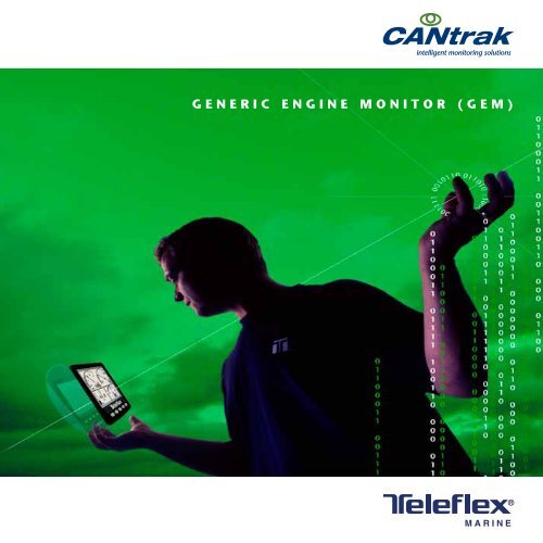
intelligent monitoring solutions<br />
<strong>GEM</strong> <strong>Manual</strong><br />
generic engine monitor (Gem)<br />
MARINE
Instructions for the<br />
Generic Engine Monitor
Before you start - what you should have<br />
What you should have<br />
(clockwise from top left):<br />
• Mounting Template/Packing list<br />
• The Generic Engine Monitor (<strong>GEM</strong>)<br />
User <strong>Manual</strong><br />
• Front Mounting Kit (4 x studs/nuts)<br />
• The Generic Engine Monitor (<strong>GEM</strong>) Display<br />
• Option Equipment: Protective Push-On<br />
Front Cover (part No. 501025)<br />
page 1
1. The Generic Engine Monitor (<strong>GEM</strong>) User <strong>Manual</strong><br />
Thank you for choosing the Generic Engine<br />
Monitor (<strong>GEM</strong>). These pages provide<br />
operating instructions for the <strong>GEM</strong> which<br />
displays J1939 or J1587 – compatible<br />
engine/transmission data. Please read<br />
through the guide before use.<br />
The <strong>GEM</strong> user-configurable application<br />
software creates graphical instrument<br />
clusters to display parameters and alarms –<br />
providing users with a time-saving solution<br />
for introducing equipment incorporating<br />
higher degrees of electronic display<br />
and control.<br />
We expect that you will be very pleased<br />
with this product and have many years of<br />
trouble-free operation. If you have any<br />
problems or ideas for improvement then<br />
we would like to hear from you.<br />
For more information please visit our<br />
web site: www.teleflexmarine.com<br />
Section/Contents<br />
Page<br />
2. Understanding The Generic Engine<br />
Monitor (<strong>GEM</strong>) 3<br />
3. Getting Started 5<br />
4. Soft Keys 6<br />
5. The Tri Display 7<br />
6. The Quad Display 10<br />
7. The Uni Display 11<br />
8. Data Parameters Monitored 12<br />
9. Active and Stored Alarm Lists 17<br />
10. Configuration Menu 19<br />
11. Pop-Up Messages and Warnings 25<br />
12. Adjusting Lighting and Contrast 26<br />
13. Preferred Screen Store 27<br />
14. Keypad Lock 27<br />
15. <strong>GEM</strong> Connection Data 28<br />
16. Typical J1939 Wiring Topology 30<br />
17. Installation 31<br />
18. Maintenance and Troubleshooting 33<br />
19. The <strong>GEM</strong> Platform 34<br />
20. Software Development Options 34<br />
fot the <strong>GEM</strong><br />
21. Glossary 35<br />
22. Important Safety and Legal Information 36<br />
page 2
2. Understanding The Generic Engine Monitor (<strong>GEM</strong>)<br />
The <strong>GEM</strong> software runs on a CANtrak display (see section 19 for further details on the CANtrak<br />
platform) with five soft keys, providing a flexible and intuitive Human-Machine Interface (HMI).<br />
The 5 soft keys access a graphical menu structure that uses standard and easily-understood icons<br />
to indicate the key’s current function. This enables the operator to select the required engine/<br />
transmission data and display it in the following formats:<br />
• Analogue gauges<br />
• Digital values<br />
• Historical trend graphs<br />
• Current and stored alarm messages<br />
Additionally, various diagnostic screens are available, allowing detailed investigation of the engine<br />
and transmission data stream. The underlying structure of the <strong>GEM</strong> and its interaction with the soft<br />
keys may be understood by Figure 1. By accessing the Configuration menu, users can customise<br />
some of the displayed data to show, for example, metric or imperial units, and various parameters<br />
such as the full-scale reading of gauges.<br />
page 3
Understanding The Generic Engine Monitor (<strong>GEM</strong>) – cont.<br />
The <strong>GEM</strong> presents a context dependent ‘button bar’ above the push buttons if any key<br />
from 1 to 4 is pressed from left to right - it disappears after 5 seconds of inactivity. This<br />
‘top level’ button bar shows the basic structure of the <strong>GEM</strong>:<br />
Figure 1<br />
Key 1: Key 2: Key 3: Key 4: Key 5:<br />
Tri Display,<br />
or Main Engine<br />
Display. Repeat<br />
presses cycle the<br />
fuel computer<br />
through various<br />
modes:<br />
Quad<br />
Display (user<br />
configurable).<br />
Repeat presses<br />
cycle the<br />
display around<br />
3 different quad<br />
view options:<br />
Uni Display<br />
showing<br />
data history<br />
(configurable).<br />
Repeat presses<br />
cycle display<br />
through available<br />
parameters:<br />
Active Alarm<br />
Display.<br />
Holding the<br />
key brings up<br />
Stored Alarms:<br />
Contrast<br />
and Lighting<br />
adjustment,<br />
or - if held for<br />
3 seconds - the<br />
Configuration<br />
menu:<br />
page 4
3. Getting Started<br />
When power is applied to the display, a start-up screen displays for approximately 7 seconds while<br />
the display performs a self test. If the display makes a ‘bleeping’ sound for longer than 1 second, selftest<br />
has failed. Users can attempt to rectify the fault by restoring factory defaults (see Configuration<br />
menu/section 10 for details); if the fault persists, contact your supplier for guidance.<br />
After the start-up screen disappears, the <strong>GEM</strong> starts displaying readings on its virtual gauges if it is<br />
connected to an active source of data. The <strong>GEM</strong> displays the ‘main engine display’ or tri-screen on<br />
initial start-up, but note that after use this changes to the screen that was last displayed (see Preferred<br />
Screen Store/section 13 for details). The <strong>GEM</strong> display modes are detailed in the following sections.<br />
page 5
4. Soft Keys<br />
The <strong>GEM</strong>’s soft keys simplify the operator interface. In use, the <strong>GEM</strong> displays a ‘button bar’ directly<br />
above the soft keys when any of the first 4 keys (keys 1 to 4, starting from the left) are pressed -<br />
with icons representing the current function of each key. Figure 2. shows the top level button bar, with<br />
icons 1 to 4 representing the gauges and alarms available, and icon 5 an ‘exit door’. Repeat presses<br />
of these buttons toggles around the display options available. The button bar will disappear after<br />
approximately 5 seconds if no further keys are pressed.<br />
Figure 2. The <strong>GEM</strong>’s top level button<br />
bar menu:<br />
Key 1: Pages icon indicating that further<br />
presses cycle through options for the<br />
screen being viewed (in this instance fuel<br />
computer modes for the main engine<br />
display)<br />
Key 2: Quad Display mode<br />
Key 3: Uni Display mode<br />
Key 4: Alarm Display mode<br />
Key 5: Exit door<br />
page 6
5. The Tri Display<br />
This <strong>GEM</strong> display mode provides three independent windows, and is intended to show the most<br />
frequently accessed vehicle data (RPM, speed, temperature and fuel). To select Tri Display, press any<br />
of the first 4 keys to show the top level button bar, and then press key 1 (the left-hand key).<br />
The parameter displayed in the top right gauge is user defined, to change the displayed data press<br />
key 5 when the button bar is visible and then keys 1 and 2 to cycle through the available parameters.<br />
Also the data displayed in the fuel computer window (Bottom left window) may be changed by<br />
repeated pressing of key 1, This is explained in more detail in the following pages. Also, attributes<br />
such as units and scales may be changed via the Configuration menu (See section 10 for details).<br />
The top window shows 2 analogue gauges;<br />
Engine RPM and Speed (maximum RPM<br />
and speed may be set via the Configuration<br />
menu). If speed data is not available the right<br />
hand gauge will display engine oil pressure.<br />
The bottom right window shows coolant<br />
temperature. The bottom left window displays<br />
the fuel computer.<br />
Figure 3.1. Tri Display, accessed via key 1.<br />
Note. Metric units are shown as default, but others may be selected<br />
via the Configuration menu.<br />
It is also possible to display speed derived<br />
from a GPS module with an NMEA 0183<br />
output - interfaced via the display’s RS232<br />
port (contact your <strong>GEM</strong> supplier for further<br />
information).<br />
page 7
5. The Tri Display (Fuel Computer Modes)<br />
Figure 3.2. A fuel computer<br />
display.<br />
Note. Metric units are shown as<br />
default, but others may be<br />
selected via the configuration<br />
menu.<br />
The lower left display window provides access to the fuel computer<br />
data and also shows fuel tank level. Upon pressing key 1 the fuel<br />
computer is highlighted, when highlighted various data can be<br />
displayed by repeat pressing of key 1. When first selected a small icon<br />
will also appear in the centre of the screen with the text “Hold Reset”.<br />
Holding key 1 at this time will perform a Trip Reset. After 2 seconds of<br />
no key presses the fuel computer will go back to normal and the icon<br />
will disappear.<br />
Data Available is similar to an automotive in-car fuel computer.<br />
Below is the list of parameters that can be displayed in the fuel computer window in alphabetical<br />
order:<br />
Distance Remaining: Calculated if Fuel Tank Capacity is set and Fuel Rate, Vehicle Speed and Fuel<br />
Level are available [Distance]<br />
Fuel Level: If available [Volume]<br />
Fuel Rate: If available [Volume/Hour]<br />
Fuel Remaining: Calculated if Fuel Tank Capacity is set and Fuel Level is available [Volume]<br />
Instantaneous Fuel Economy: Calculated if Vehicle Speed and Fuel Rate are available [Distance/<br />
Volume]<br />
Total Engine Hours: If available [Hours]<br />
Total Vehicle Distance: If available [Distance]<br />
page 8
5. The Tri Display (Fuel Computer Modes) – continued<br />
Trip Distance: Calculated since last Trip Reset if Total Vehicle Distance is available [Distance]<br />
Trip Engine Hours: Calculated since last Trip Reset if Total Engine Hours is available [Hours]<br />
Trip Fuel: Calculated since last Trip Reset if Total Fuel Used is available [Volume]<br />
Trip Fuel Economy: Calculated since last Trip Reset if Total Fuel Used and Total Vehicle Distance<br />
are available [Distance/Volume]<br />
Trip Fuel Rate: Calculated since last Trip Reset if Total Engine Hours and Total Fuel Used are<br />
available [Volume/Hour]<br />
Note. A Trip Reset affects all reset-able fuel computer parameters and can be performed by holding<br />
key 1 when the Hold Reset icon appears. The icon appears for approximately 2 seconds when<br />
the fuel computer window is first selected. Setting Total Fuel Tank Data and Fuel Tank Reset is<br />
performed via the Configuration menu.<br />
page 9
6. The Quad Display<br />
Quad Display mode provides 4 gauges. To select it, press any of the keys 1 to 4 to show the top<br />
level button bar and then key 2. Repeat presses of key 2 cycle the display around 3 separate quad<br />
screens: 4 digital gauges, 4 analogue gauges and 4 alternative analogue gauges. All 12 gauges<br />
may be selected and configured by users, providing a simple means of creating application-specific<br />
views of engine data. Gauges are selected via quad display’s ‘adjust mode’, by pressing key 5<br />
(noted by an arrow icon) when the <strong>GEM</strong> is running quad display and the button bar is visible. In<br />
adjust mode, corresponding key presses cycle the display through available parameters (listed in<br />
section 8). The selected configuration is stored even when power is removed; adjust mode<br />
is exited by pressing key 5.<br />
Figure 4. Top row: the 3 default displays available in<br />
quad-display, and adjust mode (right) which allows<br />
users to select the gauges displayed.<br />
Note. If a parameter is not available from the engine/<br />
transmission, it will not be possible to select it. If the<br />
parameter becomes unavailable while in view, ‘- - -‘ is<br />
displayed.<br />
page 10
7. The Uni Display<br />
The <strong>GEM</strong>’s Uni Display mode plots data<br />
history in one large window – in an X-Y<br />
graph format similar to a pen plotter. This<br />
mode is selected by pressing any of the first<br />
4 keys to show the top level button bar and<br />
then key 3.<br />
Figure 5. Example graph display plotting battery<br />
potential switched.<br />
Note. If a parameter is not available from the<br />
engine/transmission, it will not be possible<br />
to select it. If the parameter becomes<br />
unavailable while in view, ‘- - -’ is displayed.<br />
Data is shown in graph form, with the most<br />
recent data scrolling from right to left. The<br />
viewed time range may be adjusted in the<br />
Configuration menu from 2 minutes to 8<br />
hours in six steps. Maximum and minimum<br />
values of the Y axis (the reading span) are<br />
adjusted automatically to give an optimum<br />
view of data. The parameter displayed is<br />
selectable by repeatedly pressing key 3<br />
while in the Uni Display mode.<br />
The parameters that may be displayed are<br />
listed in section 8.<br />
page 11
8. Data Parameters Monitored<br />
This table lists the engine and transmission parameters that are monitored via the J1939 and/or the<br />
J1587 datalinks. The parameters can be displayed by the <strong>GEM</strong> in user-configurable Tri Display, Quad<br />
Display or Uni Display modes (√ indicates the parameter may be selected). DB is an abbreviation<br />
for the <strong>GEM</strong>’s internal database, which stores all data transmitted from the engine/transmission. The<br />
complete database list can be accessed on the display via the Configuration menu.<br />
Abbreviations: The units ‘MPG’ and ‘Gal’ denote US gallons. For non-US Imperial gallons (UK,<br />
Canada, etc) the units are denoted as ‘IMPG’ or ‘IGal’. N = nautical. KTS = knots<br />
Note. If a parameter is not available, it will not be possible to select it. If the parameter becomes<br />
unavailable while in view, ‘- - -‘ is displayed.<br />
Icon<br />
Parameter<br />
Datalinks Screens<br />
J1939 J1587 Tri Quad Uni DB<br />
ELECTRICAL (Volts or Amps)<br />
Electrical Potential √ √ √ √ √ √<br />
Battery Potential Switched √ √ √ √ √ √<br />
Net Battery Current √ √ √ √ √ √<br />
Alternator Potential √ √ √ √ √ √<br />
Alternator Current √ √ √ √ √ √<br />
page 12
8. Data Parameters Monitored – continued<br />
Datalinks Screens<br />
Icon<br />
Parameter<br />
J1939 J1587 Tri Quad Uni DB<br />
FUEL (L, Gal, lGal) or(L/h, Gal/h IGal/h) or (km/L, MPG or IMPG)<br />
Fuel Remaining √ √ √ √<br />
Fuel Rate √ √ √ √ √ √<br />
Instantaneous Fuel Economy √ √ √ √<br />
Trip Fuel Economy √ √ √ √<br />
Trip Fuel √ √ √ √<br />
Trip Fuel Rate √ √ √ √ √<br />
None Total Fuel Used √ √ √<br />
None Fuel Leakage 1 √ √<br />
None Fuel Leakage 2 √ √<br />
DISTANCE (km, Miles or Nmiles)<br />
Distance Remaining √ √ √ √<br />
Trip Distance √ √ √ √<br />
Total Vehicle Distance √ √ √ √<br />
page 13
8. Data Parameters Monitored – continued<br />
Icon<br />
Parameter<br />
Datalinks Screens<br />
J1939 J1587 Tri Quad Uni DB<br />
PRESSURE (kPa, PSI or bar)<br />
Fuel Delivery Pressure √ √ √ √ √ √<br />
Barometer Pressure √ √ √ √ √<br />
Auxiliary Pressure 1 √ √ √ √<br />
Boost Pressure √ √ √ √ √ √<br />
Air Inlet Pressure √ √ √ √ √<br />
Air Filter 1 Differential Pressure √ √ √ √ √<br />
None Injector Metering Rail 1 Pressure √ √ √<br />
None Injector Metering Rail 2 Pressure √ √<br />
Coolant Pressure √ √ √ √ √ √<br />
Engine Oil Pressure √ √ √ √ √ √<br />
Transmission Oil Pressure √ √ √ √ √ √<br />
None Clutch Pressure √ √ √<br />
None Air Start Pressure √ √ √<br />
None Injection Control Pressure √ √ √<br />
TEMPERATURE (ºC or ºF)<br />
Engine Coolant Temperature √ √ √ √ √ √<br />
Engine Intercooler Temperature √ √ √ √ √<br />
Engine Oil Temperature 1 √ √ √ √ √ √<br />
page 14
8. Data Parameters Monitored – continued<br />
Icon<br />
TEMPERATURE (ºC or ºF)<br />
Parameter<br />
Datalinks Screens<br />
J1939 J1587 Tri Quad Uni DB<br />
Transmission Oil Temperature √ √ √ √ √ √<br />
Turbo Oil Temperature √ √ √ √ √<br />
Fuel Temperature √ √ √ √ √<br />
Intake Manifold 1 Temperature √ √ √ √ √ √<br />
Air Inlet Temperature √ √ √ √ √<br />
Exhaust Gas Temperature √ √ √ √ √ √<br />
Auxiliary Temperature 1 √ √ √ √ √<br />
None Engine ECU Temperature √ √<br />
None Exhaust Gas Port 1 Temperature √ √<br />
None Exhaust Gas Port 2 Temperature √ √<br />
None Turbo 1 Compressor Inlet Temperature √ √<br />
PERCENTAGE (%)<br />
Fuel Level √ √ √ √<br />
Acceleration Position √ √ √ √ √<br />
None Throttle Position √ √ √<br />
Engine Oil Level √ √ √ √ √<br />
page 15
8. Data Parameters Monitored – continued<br />
Icon<br />
PERCENTAGE (%)<br />
Parameter<br />
Datalinks Screens<br />
J1939 J1587 Tri Quad Uni DB<br />
Coolant Level √ √ √ √ √<br />
Estimated Percent Fan Speed √ √ √ √<br />
Drivers Demand Percent Torque √ √<br />
Actual Engine Percent Torque √ √ √ √<br />
Torque Use at RPM √ √ √ √ √<br />
SPEED (RPM, km/h, MPH or KTS)<br />
None Input Shaft Speed √ √ √<br />
None Output Shaft Speed √ √ √<br />
Engine Speed √ √ √ √ √ √<br />
None Turbo 1 Speed √ √ √<br />
None Engine Desired Operating Speed √ √<br />
Navigation Wheel Based Vehicle Speed √ √ √ √ √<br />
TIME (h)<br />
Total Engine Hours √ √ √ √<br />
Trip Engine Hours √ √ √ √ √<br />
None Service Hours √<br />
MISCELLANEOUS<br />
None Torque Converter Lock-Up Engaged √ √<br />
Current Gear √ √ √ √<br />
Selected Gear √ √ √ √<br />
None CANTX Disable √ √<br />
page 16<br />
Note. This list is current at the time of going to press, new parameters are continually being added<br />
- the latest list may be found in the latest datasheet (available via www.teleflexmarine.com).
9. Active and Stored Alarm Lists<br />
Active alarms. When an active/current alarm is received, a flashing pop-up window appears<br />
overlaid on the current screen in use, showing details of the current alarm. When an active alarm is<br />
received, the <strong>GEM</strong> activates its internal sounder, and the external alarm output on Pin 11 (available<br />
on 7210 display models only).<br />
Figure 6. Example alarm message, plus alarm list screens showing unacknowledged conditions (black<br />
background) and acknowledged alarms (grey background). After acknowledgement, the exit key (open<br />
door icon) becomes active. J1939-standard abbreviations are used wherever possible, Note. “MS” = Most<br />
Severe, “MOD”= Moderately Severe and “LS” = Least Severe.<br />
The alarm list is accessed by pressing any key while an alarm pop-up is displayed, or by pressing<br />
any of the first 4 keys to show the button bar, and then key 4. This screen displays all current active<br />
alarms; when entered, Pin 11 External Alarm Output is deactivated (available on 7210 display models<br />
only). Alarms not yet acknowledged are shown in grey on black. Alarms already acknowledged are shown<br />
in black on grey. If engine hours data is available, the list indicates when the alarm was initiated.<br />
page 17
9. Active and Stored Alarm Lists – continued<br />
When first entering the screen, the list automatically displays the most recent alarm. The list can be<br />
scrolled using keys 1 and 2. This screen cannot be exited until all alarms have been acknowledged<br />
by pressing key 3. Alarm messages are automatically cleared from the list when no longer received<br />
by the <strong>GEM</strong>.<br />
Stored alarms. Alarms stored by engine/transmission ECU’s (i.e. not active or current but old/<br />
historical alarms) may be viewed by pressing and holding key 4 while the active alarm list screen is<br />
visible. On entry to this page, the <strong>GEM</strong> sends a data request to the engine/transmission. The engine/<br />
transmission sends the stored alarm data to the <strong>GEM</strong>, which is decoded and displayed in a similar<br />
fashion to active alarms. The <strong>GEM</strong> displays an error message if there is no response from the engine/<br />
transmission. If the engine/ transmission supports the erasure of stored alarms, they may now be<br />
erased by holding key 3.<br />
Figure 7. An example Stored Alarm List<br />
screen.<br />
page 18
10. Configuration Menu<br />
This mode allows users to set various <strong>GEM</strong> operating parameters such as imperial or metric units,<br />
scale limits for speedometer, engine service interval, etc. The configuration menu is entered by<br />
pressing and holding key 5 (the right hand key) for at least 3 seconds while the <strong>GEM</strong> is in normal<br />
operating mode. The top level configuration menu will be displayed as shown. Keys 1 and 2 then<br />
allow you to choose from SETTINGS, SYSTEM or Db VIEWER (The chosen item is highlighted in bold<br />
with an arrow pointing to it). Pressing key 4 enters the chosen sub-menu. SETTINGS allows the <strong>GEM</strong><br />
to be configured according to user preferences. SYSTEM accesses maintenance and low level system<br />
configuration settings. Db VIEWER allows the user to view all data (including that cannot be found in<br />
the graphical screens) that the <strong>GEM</strong> decodes. Each of these sub-menus is described in more detail<br />
on the pages following. Pressing key 5 exits the current menu/sub-menu. Settings are automatically<br />
stored on exit.<br />
---------<br />
Figure 8. The top level Configuration menu and its three choices of SETTINGS, SYSTEM<br />
and Db VIEWER sub-menus. Pressing Key 4 enters the menu highlighted. Key 5 (‘exit door’<br />
- the right hand button) returns you to the previous menu.<br />
page 19
10. Settings Sub-Menu (2nd Level Configuration Menu)<br />
The settings menu allows the user to enter sub-level screens<br />
to configure:<br />
Units: This menu enables the user to set the units used for<br />
speed, distance, pressure, volume and temperature.<br />
Language: Choose from various languages.<br />
Bleep: When activated, the soft keys will emit an audible<br />
“bleep”. Use this menu to switch the function on/off. An<br />
audible “bleep” will still sound if an alarm occurs.<br />
Display: The display menu allows the user to configure<br />
certain visual parameters and controls of the display.<br />
MAX RPM: This defines and restricts the upper limit of the RPM gauges displayed throughout<br />
the <strong>GEM</strong>.<br />
MAX SPEED: This defines and restricts the upper limit of the Speed gauges displayed<br />
throughout the <strong>GEM</strong>.<br />
GRAPH RANGE: This changes the resolution of the historic data displayed in the Uni Display.<br />
QUAD ADJUST: This setting allows the user to disable the ‘adjust mode’ feature in the Quad<br />
Displays. This is generally used for users who would like to fix the parameters displayed on the<br />
screens once they are happy with them. This can be re-enabled at any time.<br />
Service: Set the service interval in hours and reset the interval counter. It is important to<br />
note that setting SERVICE to 0 will disable the service interval function and the word “OFF”<br />
will be displayed.<br />
Fuel Capacity: The fuel capacity screen allows the user to enter the fuel tank capacity of<br />
the vehicle. By default the fuel tank capacity will be set to 0. Only after this has been set will the<br />
parameters Fuel Remaining and Distance Remaining be calculated.<br />
page 20
10. System Sub-Menu (2nd Level Configuration Menu)<br />
The System menu allows the user to configure or view:<br />
Demo: Switches between the <strong>GEM</strong>’s demonstration modes and<br />
the normal mode of displaying live engine/transmission data.<br />
Demo allows the <strong>GEM</strong> to operate without live data and provides<br />
3 levels of simulation data: 1 = Speed On; 2 = Speed Off;<br />
3 = Alarms On (0 = OFF). Demo is automatically turned off if live<br />
data is received.<br />
Restore Defaults: This allows<br />
you to reset all configuration information to<br />
default metric or imperial values. The default<br />
settings are:<br />
Setting Metric Imperial<br />
Language<br />
English<br />
Max. RPM 4000<br />
Max. Speed 110 kM/H 70 MPH<br />
Graph range<br />
2 mins<br />
Speed kM/H MPH<br />
Distance kM Miles<br />
Pressure kPa PSI<br />
Volume L Gal<br />
Temperature ºC ºF<br />
Demo Mode 0<br />
page 21
10. System Sub-Menu – continued<br />
Com Viewer: Displays last messages received on J1939<br />
(CAN), NMEA 0183 (GPS-derived speed over ground data) and<br />
J1587 ports. System settings stored in memory can be seen in<br />
the EEPROM Viewer.<br />
Note. This is a diagnostic feature that displays the contents of the<br />
EEPROM with the current values. This may be helpful for OEMs/<br />
users diagnosing faults.<br />
Datalink Settings:<br />
This sub-menu allows the user to configure the common datalink<br />
settings (Speed Source & Trip Source) as well as the individual<br />
J1939/J1587 settings (such as source addresses).<br />
J1939 Settings: This screen allows adjustments specific<br />
to the J1939 Datalink.<br />
Source Address 1 & 2: These settings allow the<br />
display to filter which sources it will listen to for data. Every device<br />
on a J1939 network will have a unique address (in the range 0-254)<br />
which the <strong>GEM</strong> can choose to listen to or not. The <strong>GEM</strong> can listen<br />
to 2 sources of data simultaneously (usually Engine 1 - address 0<br />
and Transmission 1 - address 3). The filter can also be removed so<br />
that the <strong>GEM</strong> will decode all incoming data regardless of its source.<br />
This is accomplished by setting “Source Address 1” to 255.<br />
page 22
10. System Sub-Menu – continued<br />
Display Address: As mentioned previously, every device has a unique address and the<br />
<strong>GEM</strong> is no different. In single engine setups the default display address is 40 (SAE recommendation).<br />
If the <strong>GEM</strong> does not display all necessary data (which is supported) please contact your engine<br />
manufacturer for advice on the value of this setting.<br />
Alarm Filter: This setting specifies whether the <strong>GEM</strong> will monitor and display alarms from<br />
all sources (GLB, global) or only the source address’ specified in the settings Source Address 1 & 2<br />
(SRC, source).<br />
SPN version: Set the Suspect Parameter Number [Version 1, 2 or 3]. Version 4 is<br />
automatically detected, but older engines will have to be set to 1, 2 or 3.<br />
Note. Consult your engine supplier to establish which SPN version is appropriate if you have<br />
problems reading alarm data.<br />
J1587 Settings: This screen allows adjustments specific<br />
to the J1587 Datalink.<br />
Source Address 1 & 2: J1587 supports source<br />
addresses in the form of the MID (Message ID) and has values<br />
defined from 128 (Engine 1) to 250 (Steering Column Unit) with<br />
all other values reserved. 255 is a special case, it indicates all<br />
data from all sources in its raw data form. Source Address 1<br />
defaults to 128 and Source Address 2 defaults to 130.<br />
Display Address: The display address allows values from 128-255.<br />
Alarm Filter: This setting specifies whether the <strong>GEM</strong> will monitor and display alarms<br />
from all sources (GLB, global) or only the source address’ specified in the settings Source Address<br />
1 & 2 (SRC, source).<br />
page 23
10. System Sub-Menu – continued<br />
Speed Source: There are currently 3 sources of speed data, which the <strong>GEM</strong> can decode. The<br />
settings for this parameter are AUTO, NMEA, WHEEL, NAV and OFF. AUTO prioritises the following<br />
sources (highest to lowest) NMEA, WHEEL (PGN 0xFEF1), NAV (PGN 0xFEF8). The remaining<br />
settings force the <strong>GEM</strong> to listen only for that particular source (and OFF stops the <strong>GEM</strong> listening to<br />
any source).<br />
Pin Settings: By default this security feature is disabled within the software. By enabling this<br />
feature the user will be prompted to enter a PIN every time the Configuration menu is entered.<br />
This is to allow the unit’s settings to be preserved and not be accidentally<br />
changed by an unauthorised user. To enable the PIN entry feature highlight<br />
the corresponding setting in the PIN Setting’s menu and press key 4 to<br />
select it. As an added security feature (to stop the pin being enabled<br />
without knowing it) the current pin must be entered (default is “1111”).<br />
Once this has been entered the feature will be enabled. It is possible<br />
to change the pin using the Pin Change menu. This will then prompt<br />
the user for the current pin and providing this is correct the <strong>GEM</strong> will<br />
prompt the user for the new pin and finally confirmation of the new pin.<br />
About: Displays the following product information<br />
ID: Serial number of the display<br />
EEPROM: Number of writes on EEPROM<br />
PART No: Unit part number<br />
VERS: Software version number<br />
CHK: Flash memory checksum<br />
SOURCE: The source of received data<br />
LIB1: Low level system library version<br />
LIB2: Low level Graphical Display Interface library version (if used).<br />
page 24
11. Pop-Up Messages and Warnings<br />
Engine service warning. In the Configuration menu, users can set the engine service interval<br />
in hours. When the <strong>GEM</strong> determines an engine service is due, it displays SERVICE REQUIRED on the<br />
splash screen that appears at power-up.<br />
Data communications failure. If the <strong>GEM</strong> cannot detect engine/transmission data<br />
broadcasts, a pop-up window with a data communications failure warning icon will appear and flash.<br />
Once engine/transmission data is detected the warning disappears and normal data display resumes.<br />
CAN TX disable. If CAN TX (transmission) is disabled, then the status will be displayed, with a<br />
pop-up window flashing with a period of approximately 1 second on, 10 seconds off. Note. This<br />
function is a requirement of the J1939 specification and is not normally of importance for the<br />
<strong>GEM</strong> applications.<br />
Data not supported. If the required data parameter is not available, the gauge will display<br />
“ - - - “ near the units and parameter icon (see below centre for example)<br />
Figure 9. Left to right. Pop-up warnings of: engine service required, a data communications failure, and<br />
CAN TX is disabled.<br />
page 25
12. Adjusting Lighting and Contrast<br />
Pressing key 5 (the right-hand key) when the menu icons are not being displayed brings up the<br />
lighting and contrast menu. The LCD has a number of back-lighting levels that allow the display<br />
to be read in the dark. The appropriate level is selected by pressing keys 1 or 2 to decrease or<br />
increase illumination. Contrast is adjusted in the same manner, using keys 3 and 4 (Figure 10).<br />
Note. The <strong>GEM</strong> monitors the temperature of the LCD and automatically adjusts display contrast as<br />
required, therefore it is not likely that a user will need to make a manual contrast adjustment unless<br />
extreme climate changes occur. The menu is exited by pressing key 5. The lighting and contrast<br />
settings are retained after the unit is switched off.<br />
Note. Resetting contrast. If the contrast has been adjusted poorly, you may restore the<br />
factory setting (a central value) by pressing keys 1 to 4 simultaneously. This action does<br />
not change other user-configured settings.<br />
Figure 10. The lighting and contrast adjust<br />
screen, showing a contrast level adjustment<br />
in progress.<br />
page 26
13. Preferred Screen Store<br />
The <strong>GEM</strong> automatically stores the current screen as a user’s preferred page, after a delay of approximately<br />
15 seconds (if no buttons are pushed). On next power-up the display will start with the splash screen,<br />
and then go to the last stored screen. Note. Selecting Restore Defaults on the Systems sub-menu of<br />
Configuration will set the main engine screen as the default display.<br />
14. Keypad Lock<br />
The <strong>GEM</strong>’s five keys can be locked, such that an operator cannot change any settings or access<br />
any other display mode. (in a similar manner to the key lock functions on a mobile phone). This is<br />
achieved by pressing and holding keys 1 and 5 simultaneously for one second. Repeating this<br />
operation resets the <strong>GEM</strong>/CANtrak back to normal operation.<br />
page 27
15. <strong>GEM</strong> Connection Data<br />
The <strong>GEM</strong> interfaces to data via the Deutsch DT0412PA connector on the rear of the display - wired as<br />
shown. Connecting harness part # 510626 is available through your local marine parts dealer, or you<br />
may source the connector components from Deutsch directly.<br />
• DT0612SA, mating connector<br />
• W12S, Wedgelock (one per connector)<br />
• 0462-201-1631, pin sockets (note that different finishes and termination methods may be selected)<br />
• 114017, sealing plug (one per unused pin location)<br />
Note. A ferrite clamp must be placed over the harness to meet EMC radiation emission requirements<br />
of BSEN60945 (Maritime navigation & radio communication equipment & systems). We recommend<br />
that the clamp should be a TDK ZCAT2032-0930, a Multicomp 33RH17 5 x 28 5 x 10 7: core, 10.7<br />
mm ID or equivalent.<br />
page 28
15. <strong>GEM</strong> Connection Data – continued<br />
Connector pin-out Signal Notes<br />
6 7<br />
1 12<br />
1 Power - Ground & power (10-30V DC). Supply should be<br />
2 Power + protected by 500mA-rated circuit breaker/fuse<br />
3 TX (+)<br />
4 TX (-)<br />
5 RX (-)<br />
6 RX (+)<br />
7<br />
8<br />
9<br />
10<br />
CAN LO<br />
(J1939 LO)<br />
CAN HI<br />
(J1939 HI)<br />
RS485A<br />
(J1587+)<br />
RS485B<br />
(J1587-)<br />
RS-232 serial port<br />
CAN2.0B port<br />
Serial port<br />
11 Output Programmable digital output for activating alarm*<br />
12 Not used Available on 7210 model only<br />
* Not available on all <strong>GEM</strong> models - refer to the datasheet for your display.<br />
page 29
16. Typical J1939 Wiring Topology<br />
Most modern engine installations include a harness with built in J1939 backbone (Check engine<br />
manufacturer’s documentation). If not, it is critical to use twisted shielded pair with a drain wire (max<br />
length 40m) terminated with 120Ω resistors at each end. In addition, all stubs should not exceed<br />
1m in length.<br />
Termination<br />
Resistor (120Ω)<br />
<strong>GEM</strong> Display<br />
Backbone<br />
(Max length 40m)<br />
Stub<br />
(Max length 1m)<br />
Engine and/or<br />
Transmission<br />
page 30<br />
Termination<br />
Resistor (120Ω)
17. Installation<br />
Front mounting instructions. Most units will be mounted onto a bulkhead, dashboard or panel —<br />
a method described below; the components required (4 x M4 studs and thumb nuts) are supplied<br />
with every <strong>GEM</strong>.<br />
Instructions:<br />
• Decide on a location.<br />
• Allow adequate clearance behind the display<br />
for cable connections, to ensure that the<br />
cables are not unduly stressed, and for<br />
ventilation. Leave sufficient cable so that the<br />
unit may be removed for servicing.<br />
• Using the template supplied with the display<br />
as a guide, cut out the mounting hole, and<br />
drill four ø4.3 mm (0.170 inch) holes for the<br />
M4 studs.<br />
• Screw the studs into the rear case; longer<br />
studs can be used (not supplied).<br />
• Connect the cable (not supplied).<br />
• Place the <strong>GEM</strong> in position, secure by screwing<br />
thumb nuts onto the studs.<br />
The front mounting kit (M4 studs and thumb<br />
nuts) supplied with the <strong>GEM</strong>, which allows<br />
the display to be mounted onto a panel or<br />
dashboard.<br />
Warning. Take care not to over tighten the studs/<br />
thumb nuts as this may damage the unit.<br />
Front mounting template. A paper mounting template for marking drill holes etc, is supplied<br />
loose with the <strong>GEM</strong>. After marking out, Teleflex advises that dimensions are verified by measurement,<br />
due to the limitations of the printing process. This is especially important if the template has been<br />
photocopied.<br />
page 31
17. Installation – continued<br />
To ensure accuracy and avoid costly repairs a Mounting Template is supplied loose with the <strong>GEM</strong>.<br />
Below is an example of this Mounting Template.<br />
Note. For best installation results ensure there is adequate ventilation behind the unit.<br />
Caution: DO NOT use this<br />
Template for the installation of<br />
your <strong>GEM</strong>, ONLY use the one<br />
supplied loose with the kit.<br />
FOR<br />
REFERENCE<br />
ONLY<br />
page 32
18. Maintenance and Troubleshooting<br />
No regular maintenance is required, except for cleaning the <strong>GEM</strong> lens as required using a soft, damp<br />
cloth. Do not use abrasive materials or solvents, specifically white spirit, petrol and acetone. Should<br />
any further attention be necessary, please contact your supplier. If you are experiencing operating<br />
problems with the <strong>GEM</strong>, check these diagnostics:<br />
Problem<br />
Unit does not power up<br />
Display is blank or black<br />
Unit bleeps at start-up and does<br />
not store settings<br />
Unit fails to display any data<br />
Unit fails to display certain<br />
parameter(s)/unable to select<br />
certain parameter(s)<br />
Active alarm messages are not<br />
displayed<br />
Stored alarm messages are not<br />
displayed<br />
Possible solution<br />
Ensure connections to unit are correct.<br />
Ensure power source is present.<br />
Adjust/reset lighting and contrast settings.<br />
Ensure temperature is within operating range of the unit.<br />
Unit has failed self-test. Contact your <strong>GEM</strong> supplier<br />
Ensure connections to unit are correct.<br />
Ensure data source supports J1939 or J1587 message<br />
protocol.<br />
Ensure the <strong>GEM</strong> supports required parameter(s)<br />
Ensure data source provides required parameter(s).<br />
Ensure data source provides alarm message data in the<br />
following format: J1939 Active Diagnostic Trouble<br />
Codes- Diagnostic Message 1 (DM1).<br />
Ensure data source provides alarm message data in the<br />
following format: J1939 Active Diagnostic Trouble<br />
Codes- Diagnostic Message 2 (DM2).<br />
page 33
19. The <strong>GEM</strong> Platform<br />
Teleflex <strong>GEM</strong> LCD displays are rugged 110 x 110 mm DIN-format modules with 5 soft keys, and offer<br />
a 160 x 128 pixel display area. This is large enough to provide great flexibility for managing the rich<br />
data available from modern electronically controlled systems. <strong>GEM</strong> is now in its fourth generation:<br />
the latest <strong>GEM</strong> 7200 family employs design-for-manufacture techniques including chip-on-tab to<br />
minimise component count and assembly operations. The <strong>GEM</strong> 7200 series of displays employ film<br />
supertwist nematic LCDs for visibility in direct sunlight – with backlighting.<br />
The <strong>GEM</strong> display features a Deutsch connector interface which allows the unit to provide ingress<br />
protection to IP67, covering immersion in water up to 1 meter deep. Units come with 3 serial interfaces:<br />
RS-232, RS-485, and a CAN 2.0B port compatible with the J1939 protocol used by many manufacturers.<br />
Differences between 7200 and 7210:<br />
7200 operates between -25°C to +75°C.<br />
7210 incorporates a heating element allowing operation between -40°C to +75°C.<br />
The <strong>GEM</strong> 7210 also includes a programmable 500mA Digital Output Driver.<br />
Data sheets are available at: www.teleflexmarine.com<br />
20. Software Development Options for the <strong>GEM</strong><br />
Customers have a range of options for creating user interfaces on <strong>GEM</strong>: Like a PC, a <strong>GEM</strong> needs<br />
application software to provide a useful function. One example of application software written by<br />
Teleflex is the <strong>GEM</strong> (Generic Engine Monitoring) software written to display electronically controlled<br />
diesel engines and transmission performance parameters and faults/alarm using the SAE J1939 and<br />
J1587 protocol. <strong>GEM</strong>s may be programmed to perform an infinite number of display, control and data<br />
logging tasks. <strong>GEM</strong>s may be programmed to perform many display, control, and data logging tasks.<br />
Please contact Teleflex Marine with your specific requirements for additional details.<br />
page 34
21. Glossary<br />
CAN Controller Area Network (also referred to as CANbus); serial communications<br />
protocol for automotive use<br />
CANtrak Intelligent CAN-compatible LCD display module<br />
FMI Failure Mode Identifier<br />
GPS Global Positioning System<br />
HMI Human-Machine Interface<br />
ISO International Standard Organisation<br />
J1939 SAE engine data protocol using CAN 2.0B<br />
J1587 Electronic Data Interchange between Microcomputer Systems in Heavy-Duty Vehicle<br />
Applications<br />
LCD Liquid Crystal Display<br />
NMEA National Marine Electronics Association; serial communications protocol for<br />
marine use<br />
PID Parameter Identifier<br />
RS-232 Standard electrical interface for serial communications<br />
RS-485 Standard differential electrical interface for serial communications<br />
SAE Society of Automotive Engineers Inc.<br />
SID Subsystem Identifier<br />
Soft keys Push-button keys whose function changes according to use<br />
SPN Suspect Parameter Number: J1939-specific fault code ID number<br />
Note. The messages, icons, error codes etc displayed by the <strong>GEM</strong> conform to J1939<br />
standards wherever possible. A copy of the relevant standards documents will be<br />
important for developers - they may be accessed and purchased via:<br />
www.sae.org/standardsdev/groundvehicle/j1939a.htm<br />
page 35
22. Important Safety and Legal Information<br />
Under no circumstances shall Teleflex or any of its subsidiary companies accept liability for any<br />
loss of data, income, incidental damage or consequential losses incurred as a result of the use<br />
of the product howsoever caused when used as a monitor for electronically-controlled engines/<br />
transmissions or other systems.<br />
• Reproduction, transfer, distribution or storage of part or all of the contents in this document in<br />
any form without written permission of Teleflex is prohibited.<br />
• Teleflex operates a policy of continuous improvement. Teleflex reserves the right to alter and<br />
improve the CANtrak displays and the <strong>GEM</strong> software without prior notice.<br />
Liquid crystal safety. If the liquid crystal display (LCD) is broken, particular care must be taken<br />
with any leaking fluid. Urgent action must be taken:<br />
• If the LCD fluid gets onto your skin wipe immediately with a suitable cloth and wash the area<br />
well with mild soap and water.<br />
• If the LCD fluid gets into your eye thoroughly rinse your eye with clean water for several minutes<br />
and then gain immediate medical assistance.<br />
• If the LCD fluid is swallowed rinse your mouth thoroughly with clean water then drink a substantial<br />
volume of water and make yourself vomit. Then gain immediate medical assistance.<br />
CE EMC Directive 89/336/EE. This product has been designed to be compliant with this<br />
directive. Compliance can only be ensured by correct installation.<br />
page 36
Teleflex Marine<br />
3831 No. 6 Road,<br />
Richmond,<br />
British Columbia,<br />
V6V 1P6<br />
Canada<br />
Tel: (001) 604-270-6899<br />
Fax: (001) 604-270-7172<br />
Email: seastar@tflexinc.com<br />
www.teleflexmarine.com<br />
©2005 Marine Canada Acquisition Limited Partnership<br />
DBA Teleflex Canada.<br />
Specifications subject to change without notice.<br />
Any trademarks used are recognised.<br />
Part Number 806612 Rev. 07<br />
August 2012<br />
MARINE