2-42271 SB6 for GSXR 1000 - MPS Racing
2-42271 SB6 for GSXR 1000 - MPS Racing
2-42271 SB6 for GSXR 1000 - MPS Racing

Create successful ePaper yourself
Turn your PDF publications into a flip-book with our unique Google optimized e-Paper software.
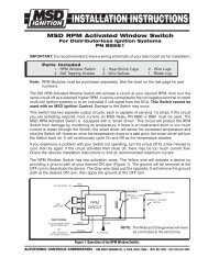
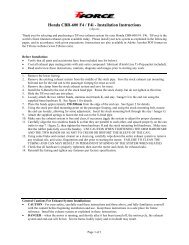
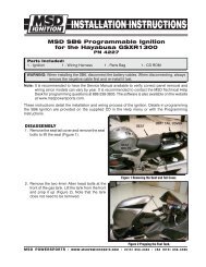
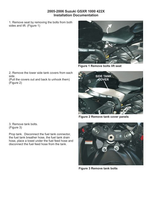
1. Remove seat by removing the bolts from both<br />
sides and lift. (Figure 1)<br />
2005-2006 Suzuki <strong>GSXR</strong> <strong>1000</strong> 422X<br />
Installation Documentation<br />
Figure 1 Remove bolts lift seat<br />
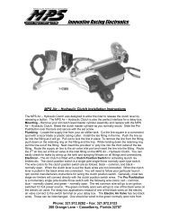
2. Remove the lower side tank covers from each<br />
side.<br />
(Pull the covers out and back to unhook them)<br />
(Figure 2)<br />
SIDE TANK<br />
COVER<br />
SIDE TANK<br />
COVER<br />
Figure 2 Remove tank cover panels<br />
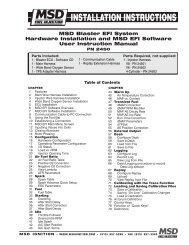
3. Remove tank bolts.<br />
(Figure 3)<br />
Prop tank. Disconnect the fuel tank connector,<br />
the fuel tank breather hose, the fuel tank drain<br />
hose, place a towel under the fuel feed hose and<br />
disconnect the fuel feed hose from the tank.<br />
Figure 3 Remove tank bolts
4. Remove Fuel Tank mounting bolt then remove<br />
the tank.<br />
(Figure 4)<br />
Figure 4 Remove tank bolt & tank<br />
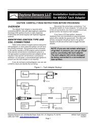
5. Disconnect IAP and IAT connectors. Remove<br />
the PAIR , PVC and vacuum hoses and the air<br />
filter box.<br />
(Figure 5)<br />
Some models will require removal of the top of<br />
the air cleaner to reach the bolts on the inside.<br />
Figure 5 Remove Air Filter box<br />
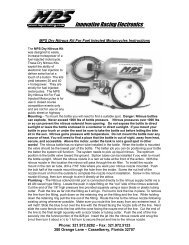
<strong>SB6</strong> Installation<br />
6. Route the harness along the right side of the<br />
bike so the furthest coil connector reaches coil<br />
number 1 and the 26 pin connector reaches the<br />
back storage compartment.<br />
(Figure 6)<br />
Figure 6 <strong>SB6</strong> Harness routing
7. Disconnect the OEM coil connectors and plug<br />
the MSD harness inline.<br />
(Figure 7) COIL 1<br />
8. Disconnect the OEM 2-pin crank connectors<br />
and plug the MSD harness inline.<br />
(Figure 8)<br />
Figure 7 Coil connections<br />
Wire Tapping:<br />
OEM<br />
Crank (+) Green/White<br />
Crank (-) Green (on one side)<br />
Blue (on othe side)<br />
MSD Harness<br />
Violet<br />
Green<br />
Verify taps have pierced the insulation and are<br />
making contact.<br />
MSD<br />
Figure 8 Crank connection<br />
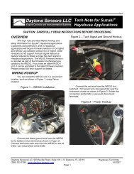
9. Locate the black 3-pin Speed sensor<br />
connector on the left side of the bike. Splice the<br />
OEM Pink wire with the MSD Red/Black wire<br />
using the supplied tap.<br />
(Figure 9)<br />
SPEED<br />
SENSOR<br />
CONNECTOR<br />
Figure 9 Speed sensor connection
Locate the OEM Black/Yellow at the clutch<br />
wire with the MSD Blue wire (Figure 10a & b).<br />
Check continuity on the PCB be<strong>for</strong>e tapping to<br />
ensure the correct wire is tapped.<br />
Clutch Wire<br />
Black/Yellow<br />
Figure 10a ECU connector<br />
Clutch Wire<br />
Black/Yellow<br />
Figure 10b ECU clutch wire tapped