SE LP10 - Access Control Solutions from ASSA ABLOY
SE LP10 - Access Control Solutions from ASSA ABLOY
SE LP10 - Access Control Solutions from ASSA ABLOY

Create successful ePaper yourself
Turn your PDF publications into a flip-book with our unique Google optimized e-Paper software.
<strong>SE</strong> <strong>LP10</strong><br />
Mortise Lock<br />
Installation Instructions<br />
A8113C (M1)<br />
2/14<br />
Copyright © 2014, Sargent Manufacturing Company, an <strong>ASSA</strong> <strong>ABLOY</strong> Group company.<br />
All rights reserved. Reproduction in whole or in part without the express written<br />
permission of Sargent Manufacturing Company is prohibited.
1<br />
2<br />
3<br />
4<br />
5<br />
6<br />
7<br />
8<br />
9<br />
10<br />
Table of Contents<br />
Warning ....................................................................................3<br />
General Description..................................................................4<br />
Technical Specifications..........................................................4<br />
Electrical Specifications...........................................................4<br />
Parts Breakdown......................................................................5<br />
Installation Instructions...........................................................7<br />
Wiring Diagrams.....................................................................15<br />
UL294 Compliance..................................................................18<br />
Mechanical Operational Check..............................................19<br />
Electrical Operational Check..................................................19<br />
Copyright © 2014, Sargent Manufacturing Company, an <strong>ASSA</strong> <strong>ABLOY</strong> Group company. All rights reserved.<br />
Reproductions in whole or in part without express written permission of Sargent Manufacturing Company is prohibited.<br />
02/15/14<br />
1<br />
Warning<br />
!!<br />
Changes or modifications to this unit not expressly approved by the party<br />
responsible for compliance could void the user’s authority to operate the equipment.<br />
FCC:<br />
This equipment has been tested and found to comply with the limits for a Class B digital device, pursuant to Part 15 of<br />
the FCC Rules. These limits are designed to provide reasonable protection against harmful interference in a residential<br />
installation. This equipment generates, uses, and can radiate radio frequency energy and, if not installed and used<br />
in accordance with the instructions, may cause harmful interference to radio communications. However, there is no<br />
guarantee that interference will not occur in a particular installation. If this equipment does cause harmful Interference<br />
to radio or television reception, which can be determined by turning the equipment off and on, the user is encouraged<br />
to try to correct the interference by one or more of the following measures:<br />
• Reorient or relocate the receiving antenna.<br />
• Increase the separation between the equipment and receiver.<br />
• Connect the equipment into an outlet on a circuit different <strong>from</strong> that to which the receiver is connected.<br />
• Consult the dealer or an experienced radio/TV technician for help.<br />
Industry Canada:<br />
This Class B digital apparatus meets all requirements of the Canadian Interference Causing Equipment Regulations.<br />
Operation is subject to the following two conditions: (1) this device may not cause harmful interference, and (2) this<br />
device must accept any interference received, including interference that may cause undesired operation.<br />
Cet appareillage numérique de la classe B répond à toutes les exigences de l’interférence canadienne causant des<br />
règlements d’équipement. L’opération est sujette aux deux conditions suivantes: (1) ce dispositif peut ne pas causer<br />
l’interférence nocive, et (2) ce dispositif doit accepter n’importe quelle interférence reçue, y compris l’interférence qui<br />
peut causer l’opération peu désirée.<br />
“This equipment complies with FCC radiation exposure limits set forth for an uncontrolled environment. This equipment<br />
should be installed and operated with minimum distance 20cm between the radiator and your body. This transmitter<br />
must not be co-located or operating in conjunction with any other antenna or transmitter.”<br />
Under Industry Canada regulations, this radio transmitter may only operate using an antenna of a type and maximum<br />
(or lesser) gain approved for the transmitter by Industry Canada. To reduce potential radio interference to other users,<br />
the antenna type and its gain should be so chosen that the equivalent isotropically radiated power (e.i.r.p.) is not more<br />
than that necessary for successful communication.<br />
Observe precautions for handling electrostatic sensitive devices.<br />
A8113C • 800-810-WIRE (9473) • www.sargentlock.com 3
<strong>SE</strong> <strong>LP10</strong> Mortise Lock<br />
2<br />
3<br />
General Description<br />
The SARGENT <strong>SE</strong> <strong>LP10</strong> mortise lock* is designed to interface with existing Wiegand Electronic <strong>Access</strong><br />
<strong>Control</strong> (EAC) panels. The reader requires 5-16 VDC for power and supports multiple high and low frequency<br />
credentials. <strong>SE</strong> <strong>LP10</strong> is backed by SARGENT’s Grade 1 hardware. The mortise lock comes with Request to<br />
Exit (RX) and Door Position (DPS) monitoring inside the lock body. It is available as 12-24 VDC. The <strong>SE</strong> <strong>LP10</strong><br />
reader provides visual (LED) and audible indicators of lock state (locked/unlocked).<br />
*Patent Pending<br />
Technical Specifications<br />
• Latch - Stainless steel 3⁄4” projection one-piece<br />
• Deadbolt - One-piece hardened stainless steel<br />
• Guardbolt - Stainless steel, non-handed<br />
• Handing - Easily field reversible without opening case<br />
• Case - 12 gauge heavy duty wrought steel<br />
• Outside lever controlled by compatible credential<br />
• Field-selectable to Fail Safe or Fail Secure<br />
• Door position switch (DPS) within lock body<br />
• Inside lever provides RX signal and retracts latch<br />
and deadbolt<br />
• Locks furnished for 1-3/4” doors. Other door<br />
thicknesses require confirmation with factory.<br />
• UL and CUL listed for use on Fire Doors<br />
• Listed to UL 294 (<strong>Access</strong> <strong>Control</strong> System Units)<br />
within the U.S. only<br />
• Wire <strong>from</strong> EAC Panel to door must be shielded<br />
with drain terminated at EAC Panel controller<br />
4<br />
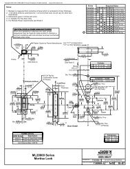
Electrical Specifications<br />
Wiegand <strong>Access</strong><br />
<strong>Control</strong> System<br />
Copyright © 2014, Sargent Manufacturing Company, an <strong>ASSA</strong> <strong>ABLOY</strong> Group company. All rights reserved.<br />
Reproductions in whole or in part without express written permission of Sargent Manufacturing Company is prohibited.<br />
Total<br />
One-Way<br />
Length of<br />
Wire Run (ft)<br />
12/24VDC System<br />
• Reader Draw = .140 Amp @12V<br />
• Actuator Draw = .015 Amp continuous<br />
• Maximum (2) locks per 1 Amp power supply<br />
(1/2 Amp current draw)<br />
Load Current @ 12VDC<br />
1/4A 1/2A 3/4A 1A 1-1/4A 1-1/2A 2A 3A<br />
100 20 18 16 14 14 12 12 10<br />
150 18 16 14 12 12 12 10 —<br />
200 16 14 12 12 10 10 — —<br />
250 16 14 12 10 10 10 — —<br />
300 16 12 12 10 10 — — —<br />
400 14 12 10 — — — — —<br />
500 14 10 10 — — — — —<br />
750 12 10 — — — — — —<br />
1,000 10 — — — — — — —<br />
1,500 10 — — — — — — —<br />
Wire Gauge Charts<br />
Total<br />
One-Way<br />
Length of<br />
Wire Run (ft)<br />
McKinney<br />
Electric<br />
Hinge<br />
<strong>SE</strong> <strong>LP10</strong><br />
Load Current @ 24VDC<br />
1/4A 1/2A 3/4A 1A 1-1/4A 1-1/2A 2A 3A<br />
100 24 20 18 18 16 16 14 12<br />
150 22 18 16 16 14 14 12 10<br />
200 20 18 16 14 14 12 12 10<br />
250 18 16 14 14 12 12 12 10<br />
300 18 16 14 12 12 12 10 —<br />
400 18 14 12 12 10 10 — —<br />
500 16 14 12 10 10 — — —<br />
750 14 12 10 10 — — — —<br />
1,000 14 10 10 — — — — —<br />
1,500 12 10 — — — — — —<br />
02/15/14<br />
HID, the HID logo, iCLASS <strong>SE</strong>, iCLASS, and Edge are trademarks or registered trademarks of HID Global in the U.S. and/or other countries. All other trademarks,<br />
service marks, and product or service names are trademarks or registered trademarks of their repsective owners.<br />
4<br />
A8113C • 800-810-WIRE (9473) • www.sargentlock.com
<strong>SE</strong> <strong>LP10</strong> Mortise Lock<br />
5<br />
Parts Breakdown<br />
Lever Hand Reverse Door<br />
6<br />
4 3 5<br />
3<br />
3<br />
2<br />
1A<br />
1* 2<br />
2<br />
2<br />
2<br />
10<br />
11<br />
9<br />
7<br />
Tools Required:<br />
• #2 Phillips screwdriver<br />
• Push pin (provided)<br />
• T10 Torx Driver<br />
• 3/32” drill bit<br />
12*<br />
• 3/4” drill bit<br />
• 5/16” drill bit<br />
• 3/8” drill bit<br />
• 7/16” drill bit<br />
• 1” bore<br />
• 2-1/8” bore<br />
A8113C • 800-810-WIRE (9473) • www.sargentlock.com 5<br />
7<br />
15<br />
13<br />
*Patent Pending<br />
14<br />
8<br />
15<br />
14<br />
02/15/14 Copyright © 2014, Sargent Manufacturing Company, an <strong>ASSA</strong> <strong>ABLOY</strong> Group company. All rights reserved.<br />
Reproductions in whole or in part without express written permission of Sargent Manufacturing Company is prohibited.
<strong>SE</strong> <strong>LP10</strong> Mortise Lock<br />
Parts Breakdown (Continued)<br />
Lever Hand Reverse Door<br />
ITEM PART # Description Req.<br />
1* 52-4524 <strong>SE</strong> Reader Assembly- Black 1<br />
52-4525 <strong>SE</strong> Reader Assembly- Gray<br />
52-4528 FIPS <strong>SE</strong> Reader Assembly- Black (200 bit Wiegand output)<br />
52-4529 FIPS <strong>SE</strong> Reader Assembly- Gray (200 bit Wiegand output)<br />
52-4567 FIPS <strong>SE</strong> Reader Assembly- Black (75 bit Wiegand output)<br />
52-4568 FIPS <strong>SE</strong> Reader Assembly- Gray (75 bit Wiegand output)<br />
1A -- <strong>SE</strong> Mounting Plate 1<br />
2 52-4539 Screw Pack 1<br />
3 52-4542 Fire Block Kit 1<br />
Copyright © 2014, Sargent Manufacturing Company, an <strong>ASSA</strong> <strong>ABLOY</strong> Group company. All rights reserved.<br />
Reproductions in whole or in part without express written permission of Sargent Manufacturing Company is prohibited.<br />
4 52-1359 Trim Bezel- Black 1<br />
52-1360 Trim Bezel- Gray<br />
5 52-5218 Inside Mounting Plate 1<br />
6 52-5196 Inside Escutcheon With Thumb Turn 1<br />
82-0706 Inside Escutcheon Without Thumb Turn<br />
7 -- Reference <strong>SE</strong> <strong>LP10</strong> Catalog For Available Lever Styles 1<br />
8 -- Reference <strong>SE</strong> <strong>LP10</strong> Catalog For Available Rose Styles 1<br />
9 82-3211 Trim Pack 1<br />
79-2162 DL Trim Pack 1<br />
10 -- Rosette Spring Assembly 1<br />
11 -- Cylinder (Size 41) 1<br />
12* Lock Body "M1-82270-12/24 VDC x Finish" w/out Deadbolt, Fail Safe 1<br />
"M1-82271-12/24 VDC x Finish" w/out Deadbolt, Fail Secure 1<br />
"M1-82272-12/24 VDC x Finish" w/out Deadbolt, Fail Safe, Both Levers Lock 1<br />
"M1-82273-12/24 VDC x Finish" w/out Deadbolt, Fail Secure, Both Levers Lock** 1<br />
"M1-82280-12/24 VDC x Finish" w/ Deadbolt, Fail Safe 1<br />
"M1-82281-12/24 VDC x Finish" w/ Deadbolt, Fail Secure 1<br />
"M1-82282-12/24 VDC x Finish" w/ Deadbolt, Fail Safe, Both Levers Lock 1<br />
"M1-82283-12/24 VDC x Finish" w/ Deadbolt, Fail Secure, Both Levers Lock** 1<br />
13 82-0579 Outside Faceplate w/ Deadbolt 1<br />
82-0578 Outside Faceplate w/out Deadbolt 1<br />
14 82-0110 Strike Plate 1<br />
15 77-4236 Lock Body and Strike Screw Pack 2<br />
16 A8123 Field Prep Template (not shown) 1<br />
17 4702 Door Manufacturer Template (not shown) 1<br />
18 A8113A Installation Instructions (not shown) 1<br />
19 A8129 Outside Field Prep Template (not shown) 1<br />
*Patent Pending<br />
**CAUTION: Not recommended for use on any door used for Life Safety Egress<br />
02/15/14<br />
6<br />
A8113C • 800-810-WIRE (9473) • www.sargentlock.com
<strong>SE</strong> <strong>LP10</strong> Mortise Lock<br />
6<br />
Installation Instructions<br />
1 Door Preparation<br />
A. Verify Hand and Bevel of Door<br />
Stand on outside of locked door when determining door hand.<br />
Left Hand<br />
Hinges Left.<br />
Open Inward.<br />
“LH”<br />
Left Hand<br />
Reverse Bevel<br />
Hinges Left.<br />
Open Outward<br />
“LHRB”<br />
Fig. 1A<br />
Right Hand<br />
Hinges Right.<br />
Open Inward.<br />
“RH”<br />
Right Hand<br />
Reverse Bevel<br />
Hinges Right.<br />
Open Outward<br />
“RHRB”<br />
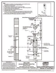
B. Door Preparation<br />
Prepare door according to appropriate template. If necessary, refer to website<br />
www.intelligentopenings.com.<br />
• Prior to installation, make sure all holes are free of burrs, debris, and sharp edges.<br />
• If doors are not properly reinforced per ANSI 115.2, commercially available reinforcements<br />
should be installed.<br />
• Templates:<br />
Pre-drill Holes (2 places)<br />
Outside Cylinder Hole<br />
(70/71, 72/73, 80/81,<br />
82/83 functions only)<br />
o Field Template: A8123 and A8129 (ships with product).<br />
o Door Manufacturer’s Template: 4702 metal and wood door.<br />
Lever Handle Hole<br />
Pre-drilled and/or<br />
Tapped Holes (2 Places)<br />
Outside of Door<br />
Mortise<br />
Area<br />
Fig. 1B<br />
(Wood Door Shown)<br />
A8113C • 800-810-WIRE (9473) • www.sargentlock.com 7<br />
Inside of Door<br />
Pre-drill Holes (4 places)<br />
Inside Wire Hole<br />
Thumb Turn Hole<br />
Lever Handle Hole<br />
02/15/14 Copyright © 2014, Sargent Manufacturing Company, an <strong>ASSA</strong> <strong>ABLOY</strong> Group company. All rights reserved.<br />
Reproductions in whole or in part without express written permission of Sargent Manufacturing Company is prohibited.
<strong>SE</strong> <strong>LP10</strong> Mortise Lock<br />
2 How to Change Hand of Lock body<br />
A. Reverse Lock Hand<br />
Red surface of locking piece must face the<br />
outside/locked side of door. To rotate locking<br />
piece (Fig. 2A):<br />
1. Position lock body with red surface of<br />
locking piece visible.<br />
2. Insert blade type screwdriver into locking<br />
piece slot to rotate locking piece toward<br />
back of lock body.<br />
3. Rotate the locking piece 180° until RED<br />
surface is on opposite side.<br />
Note: Red indicates locked side (outside).<br />
Locking Guide Slot:<br />
Red color indicates<br />
locked side.<br />
Fig. 2A<br />
Push In<br />
Right Hand<br />
Lock Shown<br />
B. Reverse Latch Hand<br />
Copyright © 2014, Sargent Manufacturing Company, an <strong>ASSA</strong> <strong>ABLOY</strong> Group company. All rights reserved.<br />
Reproductions in whole or in part without express written permission of Sargent Manufacturing Company is prohibited.<br />
02/15/14<br />
Beveled surface of latch must face strike (Fig. 2B).<br />
The deadlatch is self adjusting.<br />
To change hand of latchbolt:<br />
1. Insert screwdriver into the spade<br />
shaped slot.<br />
2. Rotate screwdriver 90º to push latch out<br />
until back of latch clears lock front; then<br />
rotate latch 180º.<br />
Latch will then re-enter lock body.<br />
Note: Latch cannot be unscrewed.<br />
3 Configure the DIP Switch Settings<br />
IMPORTANT: The 3-position DIP-switch settings<br />
located at the bottom of the mortise lock body<br />
must be set prior to lock installation.<br />
1 2 3<br />
DIP Switch<br />
RH & RHR<br />
8<br />
Handing<br />
Triangular Slot<br />
LH & LHR<br />
Check Polarity:<br />
Verify + (red wire)<br />
Normally<br />
Open<br />
RX Output<br />
Normally<br />
Closed<br />
Fig. 2B<br />
Actuator Operation<br />
Fail Safe<br />
Latchbolt<br />
Fail Secure<br />
A8113C • 800-810-WIRE (9473) • www.sargentlock.com
<strong>SE</strong> <strong>LP10</strong> Mortise Lock<br />
4 Install Lock body<br />
1. Wires and connectors go into the mortised area and out of the inside cylinder hole.<br />
2. Insert mortise lock body into mortise door preparation.<br />
3. Carefully feed wires <strong>from</strong> mortise lock through the non-cylinder side hole of the door preparation.<br />
4. Hold lock body loosely in place with (2) lock body screws (wood or metal depending on type of door).<br />
Note: Do not completely tighten screws at this time.<br />
Inside of Door<br />
(2) #12-24 x 1/2”<br />
Flat Head Philips<br />
Screws (Metal Doors)<br />
A8113C • 800-810-WIRE (9473) • www.sargentlock.com 9<br />
(2)#12 x 1-1/4” Flat<br />
Head Wood Screws<br />
(Wood Doors)<br />
Fig. 4<br />
02/15/14 Copyright © 2014, Sargent Manufacturing Company, an <strong>ASSA</strong> <strong>ABLOY</strong> Group company. All rights reserved.<br />
Reproductions in whole or in part without express written permission of Sargent Manufacturing Company is prohibited.
<strong>SE</strong> <strong>LP10</strong> Mortise Lock<br />
5 Installation of Card Reader and Inside Mounting Plate<br />
NOTE: Feed mortise connectors through the corresponding hole on the<br />
mounting plate.<br />
1. Attach the mounting plate using the two lower screws ONLY (Fig. 5A).<br />
2. For fire-rated doors only, install fire shield (Fig. 5B).<br />
3. Attach reader backplate to the fire shield using two #8 x 1/2” Phillips flat<br />
head self drill screws (Fig. 5B).<br />
4. Fit trim bezel around the reader. Ensure access hole in the bezel aligns<br />
with screw hole on reader. The reader should be mounted so the holes<br />
face the bottom of door.<br />
5. Align top of reader with top of backplate. Pivot reader down until seated.<br />
Guide wires as needed to avoid pinching.<br />
6. Secure the reader with (1) #6-32 x 3/8” Phillips or anti-tamper security torx<br />
screw to the mounting plate (Fig. 5C).<br />
Inside of Door<br />
(2) 8-32 x 3/8”<br />
Phillips Flat<br />
Head Self-<br />
Drilling Screw<br />
Outside of Door<br />
Fig. 5A<br />
Copyright © 2014, Sargent Manufacturing Company, an <strong>ASSA</strong> <strong>ABLOY</strong> Group company. All rights reserved.<br />
Reproductions in whole or in part without express written permission of Sargent Manufacturing Company is prohibited.<br />
Reader<br />
Backplate<br />
Fig. 5B<br />
Fire Shield<br />
Reader Cable<br />
Fig. 5C<br />
Trim Bezel<br />
02/15/14<br />
10<br />
A8113C • 800-810-WIRE (9473) • www.sargentlock.com
<strong>SE</strong> <strong>LP10</strong> Mortise Lock<br />
6 Wire Connections<br />
1. Connect ElectroLynx (4 and 8 pin) <strong>from</strong> the door harness to<br />
P1 and P2 on the reader assembly. See Figure 6A.<br />
Note: Connectors only go on one way.<br />
2. Connect 2-pin connector <strong>from</strong> lock body to P4 (2-pin) on<br />
reader harness.<br />
3. Connect 6-pin connector <strong>from</strong> lock body to P3 (6-pin) on<br />
reader harness.<br />
4. Carefully tuck ElectroLynx connectors into 1 inch hole in<br />
door. See photo in Figure 6B.<br />
Notes: Neatly fold the wires into the remaining space to<br />
prevent pinching wires when mounting escutcheon. Do<br />
not tuck extra mortise lock body wires back inside the lock<br />
body cylinder hole. Do not offset connectors and be sure<br />
they are completely seated.<br />
Fig. 6B<br />
Fig. 6A<br />
7 Fire Plate Installation and Earth Ground Connection<br />
1. Remove lower right screw <strong>from</strong> mounting plate. Feed screw through green/yellow<br />
ground wire ring terminal. Reinstall screw. Ensure that green/yellow wire points toward top of<br />
door in order to avoid interference with escutcheon<br />
2. Install the fire plate to the mounting plate. Use caution not to trap wires between pad and<br />
mounting plate. Fasten plate with two #8 x 1 1/4” Phillips pan head self-drilling screws.<br />
Note: For non-fire rated doors, omit fire plate.<br />
Inside of Door<br />
Fig. 7A<br />
A8113C • 800-810-WIRE (9473) • www.sargentlock.com 11<br />
Fig. 7B<br />
02/15/14 Copyright © 2014, Sargent Manufacturing Company, an <strong>ASSA</strong> <strong>ABLOY</strong> Group company. All rights reserved.<br />
Reproductions in whole or in part without express written permission of Sargent Manufacturing Company is prohibited.
<strong>SE</strong> <strong>LP10</strong> Mortise Lock<br />
8 Outside Cylinder Installation<br />
NOTE: Verify that the lock body wires do not contact any moving parts as cylinder and deadbolt move.<br />
1. Verify orientation of cylinder so that SARGENT logo is right-side up (Fig. 8A).<br />
2. Withdraw the key about 25% out of the cylinder before inserting into the escutcheon (Fig. 8B).<br />
3. Rotate cylinder until it is nearly flush with the edge of rosette and the SARGENT<br />
logo is positioned correctly (Fig. 8A).<br />
Note: Do not attempt to tighten all the way.<br />
4. Tighten the cylinder clamp set screw to prevent<br />
unscrewing of the cylinder (Fig. 8C).<br />
5. Test cylinder function:<br />
• 70/71/72/73 Function:<br />
Key retracts latch.<br />
• 80/81/82/83 Function:<br />
Key retracts latch and projects<br />
and retracts deadbolt.<br />
• Ensure smooth operation of<br />
latchbolt and deadbolt.<br />
NOTE: Use lever handle holes<br />
to manipulate mortise to ease<br />
thread engagement of cylinder.<br />
Outside of Door<br />
Cylinder Set Screw<br />
Phillips<br />
Screwdriver<br />
Copyright © 2014, Sargent Manufacturing Company, an <strong>ASSA</strong> <strong>ABLOY</strong> Group company. All rights reserved.<br />
Reproductions in whole or in part without express written permission of Sargent Manufacturing Company is prohibited.<br />
IMPORTANT: Position cylinder so that the<br />
SARGENT logo is positioned correctly.<br />
Correct<br />
Fig. 8A<br />
Incorrect<br />
Fig. 8B<br />
Fig. 8C<br />
02/15/14<br />
12<br />
A8113C • 800-810-WIRE (9473) • www.sargentlock.com
<strong>SE</strong> <strong>LP10</strong> Mortise Lock<br />
9 Inside Outside Lever and Inside Adapter Plate Assembly<br />
1. With outside lever horizontal, insert the mounting post through outside of door and lock body.<br />
Make certain the lever spindle is properly engaged inside the lock body (Fig. 9A).<br />
2. On the inside of the door, insert spindle into square hole of mortise lock (Fig. 9B).<br />
3. Slide inside adapter and plate<br />
assembly over spindle and<br />
loosely secure with (2) 8-32 X 5/8”<br />
Phillips oval head and lock washer<br />
machine screws.<br />
Be sure to rotate the set screw hole<br />
so the hole (Studio Collection only)<br />
faces the hinge side and seat inside<br />
spindle fully into the lock body.<br />
4. Securely tighten the<br />
lock body screws.<br />
Outside of Door<br />
Lock Body<br />
Screw<br />
Inside of Door<br />
8-32 X 5/8”<br />
Phillips Oval<br />
Head and<br />
Lock Washer<br />
Machine<br />
Screw<br />
Fig. 9A<br />
Fig. 9B<br />
10 Install Inside Escutcheon Assembly<br />
1. Carefully and neatly fold back lock body wires.<br />
2. For locks equipped with deadbolts, align inside escutcheon<br />
turn lever with slot in lock body. Adjust wires as necessary<br />
to ensure they are clear of inside escutcheon. Seat inside<br />
escutcheon against door.<br />
3. Tighten the inside escutcheon securely to the mounting<br />
plate with the Phillips flat head machine screws provided.<br />
Use 8- 32 x 5/8” for the top of the escutcheon and the 8-<br />
32 x 1/4” screws for the bottom of the escutcheon located<br />
under the turn lever.<br />
4. Be sure the turn assembly and the deadbolt function<br />
properly.<br />
A8113C • 800-810-WIRE (9473) • www.sargentlock.com 13<br />
Fig. 10<br />
Inside of Door<br />
8-32 X 5/8”<br />
Phillips<br />
Flat Head<br />
Undercut<br />
Machine<br />
Screw<br />
8-32 X 1/4”<br />
Phillips<br />
Flat Head<br />
Undercut<br />
Machine<br />
Screw<br />
02/15/14 Copyright © 2014, Sargent Manufacturing Company, an <strong>ASSA</strong> <strong>ABLOY</strong> Group company. All rights reserved.<br />
Reproductions in whole or in part without express written permission of Sargent Manufacturing Company is prohibited.
<strong>SE</strong> <strong>LP10</strong> Mortise Lock<br />
11 Install Inside Rose and Inside Lever Assembly<br />
1. Rotate the inside rose first counter clockwise<br />
to seat the threads then clockwise to<br />
securely tighten.<br />
2. Slide lever handle onto spindle until fully<br />
seated. Be sure handle is horizontal and<br />
facing the hinge side of the door. Push lever<br />
onto spindle so minimum gap is visible.<br />
3. Tighten the set screw securely with<br />
a 1/8” hex wrench.<br />
4. Before closing the door, test that the<br />
lever is functional and ensure<br />
smooth operation of the<br />
latchbolt and deadbolt.<br />
Spindle<br />
Rose<br />
Set Screw<br />
Inside of Door<br />
Fig. 11A<br />
Inside Lever<br />
Fig. 11B<br />
12 Attach Front Plate<br />
Copyright © 2014, Sargent Manufacturing Company, an <strong>ASSA</strong> <strong>ABLOY</strong> Group company. All rights reserved.<br />
Reproductions in whole or in part without express written permission of Sargent Manufacturing Company is prohibited.<br />
1. Attach front plate with (2) 8-32x1/4” flat head screws<br />
and tighten securely.<br />
Fig. 12<br />
Outside of Door<br />
(2) 8-32x1/4”<br />
Flat Head Screws<br />
02/15/14<br />
14<br />
A8113C • 800-810-WIRE (9473) • www.sargentlock.com
<strong>SE</strong> <strong>LP10</strong> Mortise Lock<br />
7<br />
Wiring Diagrams<br />
Product 8 PIN CONNECTOR 4 PIN CONNECTOR<br />
1-Black 2-Red 3-White 4-Green 5-Orange 6-Blue 7-Brown 8-Yellow 9-Violet 10-Gray 11-Pink 12-Tan<br />
ACCESS CONTROL DEVICES: <strong>SE</strong> <strong>LP10</strong> Mortise, ElectroLynx wire Color / Function assignments<br />
SARGENT -<br />
<strong>SE</strong> <strong>LP10</strong>,<br />
Mortise<br />
12VDC<br />
(Reader)<br />
WIE-<br />
GAND<br />
WIE-<br />
GAND<br />
NEG POS DATA_1 DATA_0 NO COM REF.<br />
*DIA-<br />
GRAMS<br />
RX RX EGND OPTION 12/24 VDC<br />
(LOCK RELAY)<br />
REF.<br />
*DIA-<br />
GRAMS<br />
DPS<br />
(NC)<br />
DPS<br />
(COM)<br />
NEG POS DPS DPS<br />
*Diagrams on following pages<br />
The <strong>SE</strong> <strong>LP10</strong> reader can be configured for various modes of LED and beeper operation. HID programming<br />
cards are supported to configure the behavior for LED and beeper activity. (Call 1-800-<br />
810-WIRE (9473) for details.) Along with the programming cards, the OPTION wire can be connected<br />
within the panel and the lock in order to enable some of the listed features. See chart below:<br />
Default Operation Mode:<br />
• Red LED ‘ON’ when powered.<br />
• Presenting a 13.56MHz or 125 kHz credential causes LED to briefly<br />
turn green and then return to red state.<br />
• Presenting a FIPS 201 PIV credential causes LED to turn amber as<br />
credential is authenticated. Reader emits a short beep when credential<br />
is successfully read.<br />
• Reference *Diagram #1 as a function of power requirement (12VDC<br />
or 24VDC).<br />
Note: OPTION wire is unconnected.<br />
PIN 8 (Yellow – OPTION)<br />
PIN 6 (Blue – RX COM)<br />
PIN 4 (Green – Data 0)<br />
PIN 1 (Black – Reader NEG)<br />
PIN 3 (White – Data 1)<br />
PIN 5 (Orange – RX NO)<br />
PIN 7 (Brown - EGND)<br />
Optional Operation Mode:<br />
• Connect selected option wire <strong>from</strong> reader to ElectroLynx cable pin 8<br />
Note: For fire rated doors solder sleeve (P/N 52-1373) to be applied<br />
to desired lead 2.5” <strong>from</strong> base of reader. See diagram for application.<br />
• Connect Yellow OPTION wire <strong>from</strong> ElectroLynx cable to desired EAC<br />
panel control line.<br />
Reference Diagram #2<br />
• As appropriate, use configuration card to activate desired mode on<br />
reader.<br />
Reader Wire Color<br />
YELLOW<br />
BLUE<br />
ORANGE<br />
BROWN<br />
VIOLET<br />
Optional Function Chart<br />
Contact Factory For Reader Configuration Card Requirements<br />
Functional Assignment<br />
Beeper <strong>Control</strong><br />
Hold <strong>Control</strong><br />
GREEN LED <strong>Control</strong><br />
RED LED <strong>Control</strong><br />
Tamper Detect (open collector output <strong>from</strong> reader)<br />
ElectroLynx P1-8. Use appropriate configuration card to activate function on reader.<br />
Note: When Yellow OPTION wire is tied directly into EAC panel relay, no<br />
AC signals should be applied on wire or door reader performance will be<br />
impacted.<br />
A8113C • 800-810-WIRE (9473) • www.sargentlock.com 15<br />
PIN 4 (Tan –DPS NC )<br />
PIN 2 (Gray – Lock POS)<br />
PIN 1 (Violet – Lock NEG)<br />
PIN 3 (Pink – DPS)<br />
Note: NC= Normally Closed<br />
NO= Normally Open<br />
Wire<br />
Strip 1/4”<br />
Solder Sleeve<br />
Overlap wires as shown. Use heat gun to set wires.<br />
02/15/14 Copyright © 2014, Sargent Manufacturing Company, an <strong>ASSA</strong> <strong>ABLOY</strong> Group company. All rights reserved.<br />
Reproductions in whole or in part without express written permission of Sargent Manufacturing Company is prohibited.
<strong>SE</strong> <strong>LP10</strong> Mortise Lock<br />
Typical <strong>SE</strong> <strong>LP10</strong> Mortise Application Diagram (12/24VDC Lock)<br />
DIAGRAM #1 – MODE 1: OPTION WIRE NOT U<strong>SE</strong>D = RED LED ON WHEN POWERED<br />
Standard Application Shown - For Alternative Applications Contact 1-800-810-WIRE (9473)<br />
Reader Electronics Requires 5 to 16VDC Filtered and Regulated<br />
12/24VDC System<br />
• Reader Draw = .140 Amp<br />
• Actuator Draw = .015 Amp continuous<br />
• Maximum (2) locks per 1 Amp power supply (1/2 Amp current draw)<br />
120 VAC<br />
Input<br />
Black (Hot)<br />
H N G<br />
12/24VDC<br />
- +<br />
White (Neutral)<br />
Green (Gnd)<br />
Lock body<br />
Power Supply<br />
(By Others)<br />
Copyright © 2014, Sargent Manufacturing Company, an <strong>ASSA</strong> <strong>ABLOY</strong> Group company. All rights reserved.<br />
Reproductions in whole or in part without express written permission of Sargent Manufacturing Company is prohibited.<br />
12 Conductor<br />
ElectroLynx Harness<br />
From McKinney<br />
<strong>SE</strong> <strong>LP10</strong><br />
QC12 Electric<br />
Hinge From<br />
McKinney<br />
READER NEG - Black, 1<br />
READER POS - Red, 2<br />
DATA 1 - White, 3<br />
DATA 0 - Green, 4<br />
RX (NO/NC) - Orange, 5<br />
RX (COM) - Blue, 6<br />
*EGND- Brown, 7<br />
OPTION - Yellow, 8<br />
LOCK NEG - Violet, 9<br />
LOCK POS - Gray, 10<br />
DPS (NC) - Pink, 11<br />
DPS (COM) - Tan, 12<br />
Not Used<br />
*IMPORTANT: Pin 7 must be tied to earth ground in the access control panel.<br />
Failure to follow proper ESD safe grounding procedures could lead to equipment failure.<br />
(-)<br />
(+)<br />
DATA 1<br />
DATA 0<br />
RX<br />
RX<br />
DPS<br />
DPS<br />
12VDC<br />
Use (NC) for<br />
Fail Safe<br />
Operation<br />
(NO) Fail<br />
Secure<br />
Operation<br />
Electronic<br />
<strong>Access</strong><br />
<strong>Control</strong><br />
Panel<br />
(By Others)<br />
Lock Relay<br />
02/15/14<br />
16<br />
A8113C • 800-810-WIRE (9473) • www.sargentlock.com
<strong>SE</strong> <strong>LP10</strong> Mortise Lock<br />
Typical <strong>SE</strong> <strong>LP10</strong> Mortise Application Diagram (12/24VDC Lock)<br />
DIAGRAM #2 – MODE 2: OPTION WIRE TO EAC PANEL = EAC PANEL CONFIGURABLE<br />
Standard Application Shown - For Alternative Applications Contact 1-800-810-WIRE (9473)<br />
Reader Electronics Requires 5 to 16VDC Filtered and Regulated<br />
12/24VDC System<br />
• Reader Draw = .140 Amp<br />
• Actuator Draw = .015 Amp continuous<br />
• Maximum (2) locks per 1 Amp power supply<br />
(1/2 Amp v current draw)<br />
120 VAC<br />
Input<br />
Black (Hot)<br />
H N G<br />
12/24VDC<br />
- +<br />
White (Neutral)<br />
Green (Gnd)<br />
Lock body<br />
Power Supply<br />
(By Others)<br />
12 Conductor<br />
ElectroLynx Harness<br />
From McKinney<br />
<strong>SE</strong> <strong>LP10</strong><br />
QC12 Electric<br />
Hinge From<br />
McKinney<br />
READER NEG - Black, 1<br />
READER POS - Red, 2<br />
DATA 1 - White, 3<br />
DATA 0 - Green, 4<br />
RX (NO/NC) - Orange, 5<br />
RX (COM) - Blue, 6<br />
*EGND- Brown, 7<br />
OPTION - Yellow, 8<br />
LOCK NEG - Violet, 9<br />
LOCK POS - Gray, 10<br />
DPS (NC) - Pink, 11<br />
DPS (COM) - Tan, 12<br />
*IMPORTANT: Pin 7 must be tied to earth ground in the access control panel.<br />
A8113C • 800-810-WIRE (9473) • www.sargentlock.com 17<br />
Failure to follow proper ESD safe grounding procedures could lead to equipment failure.<br />
(-)<br />
(+)<br />
DATA 1<br />
DATA 0<br />
RX<br />
RX<br />
12VDC<br />
OPTION<br />
DPS<br />
DPS<br />
Use (NC) for<br />
Fail Safe<br />
Operation<br />
(NO) Fail<br />
Secure<br />
Operation<br />
Electronic<br />
<strong>Access</strong><br />
<strong>Control</strong><br />
Panel<br />
(By Others)<br />
Lock Relay<br />
02/15/14 Copyright © 2014, Sargent Manufacturing Company, an <strong>ASSA</strong> <strong>ABLOY</strong> Group company. All rights reserved.<br />
Reproductions in whole or in part without express written permission of Sargent Manufacturing Company is prohibited.
<strong>SE</strong> <strong>LP10</strong> Mortise Lock<br />
8<br />
UL294 Compliance<br />
<strong>SE</strong> <strong>LP10</strong> 8200 UL294 Application Diagram<br />
UL294 Requirements<br />
• HID EDGE E400 or ES400<br />
• POE Injector Altronix Netway1<br />
• SARGENT 3540 / Securitron BPS-24-2<br />
• HES 2001M MOV / Bridge (Optional)<br />
• OPTION Wire Use as Required<br />
Copyright © 2014, Sargent Manufacturing Company, an <strong>ASSA</strong> <strong>ABLOY</strong> Group company. All rights reserved.<br />
Reproductions in whole or in part without express written permission of Sargent Manufacturing Company is prohibited.<br />
12 Conductor<br />
ElectroLynx Harness<br />
From McKinney<br />
<strong>SE</strong> <strong>LP10</strong><br />
QC12 Electric<br />
Hinge From<br />
McKinney<br />
READER NEG - Black, 1<br />
READER POS - Red, 2<br />
DATA 1 - White, 3<br />
DATA 0 - Green, 4<br />
RX (NO) - Orange, 5<br />
RX (COM) - Blue, 6<br />
EGND- Brown, 7<br />
OPTION - Yellow, 8<br />
Use as Required<br />
LOCK NEG - Violet, 9<br />
Red<br />
LOCK POS - Gray, 10<br />
Red/Green<br />
Tape Purple/Black<br />
DPS (NC) - Pink, 11<br />
Wires (Unused)<br />
DPS (COM) - Tan, 12<br />
120 VAC<br />
To NC Fire Alarm Contacts<br />
H<br />
F2<br />
FA<br />
F1<br />
H<br />
N<br />
G<br />
120 VAC Input Fire Alarm Contacts<br />
HES<br />
24 VDC Positive Outputs<br />
24 VDC Negative Outputs<br />
2001M<br />
P1<br />
P2<br />
P3<br />
P4<br />
R1<br />
R2<br />
R3<br />
R4<br />
Black<br />
Black<br />
*IMPORTANT: Pin 7 must be tied to earth ground in the access control panel.<br />
Wiring in accordance with the NEC, ANSI/NFPA 70<br />
Fail secure installations are subject to approval of local AHJ<br />
P22 GND<br />
P23 PWR<br />
P23 DATA 1<br />
P23 DATA 0<br />
P106 REX (+)<br />
P106 REX (-)<br />
P105 DS COM<br />
P105 DS NO<br />
ALTRONIX NETWAY1<br />
ALTRONIX<br />
POWER INPUTS<br />
NON-POLAR<br />
P106 DOOR MON (+)<br />
P106 DOOR MON (-)<br />
Fail secure installations shall permit use of Listed panic hardware to allow emergancy<br />
exit <strong>from</strong> the protected area.<br />
Failure to follow proper ESD safe grounding procedures could lead to equipment failure.<br />
*UL294 is a United States based standard.<br />
ALTRONIX<br />
RJ45 PORTS<br />
IN<br />
IN used for<br />
Networking/<br />
Monitoring<br />
Connection<br />
CAT5e OR<br />
GREATER<br />
CABLE<br />
RJ45<br />
PORT<br />
HID EDGE E400/<br />
ES400<br />
OUT<br />
02/15/14<br />
18<br />
A8113C • 800-810-WIRE (9473) • www.sargentlock.com
<strong>SE</strong> <strong>LP10</strong> Mortise Lock<br />
9<br />
Mechanical Operational Check<br />
For 82280-82283 & 82270-82273 Function mortise locks with cylinders:<br />
1. Insert key into cylinder and rotate: There should be no friction against<br />
lock case, wire harness or any other obstructions.<br />
2. The key will retract the latch: Key should rotate freely.<br />
3. When the deadbolt is thrown: Ensure that the key retracts both the<br />
deadbolt and the latch.<br />
4. Inside lever: When used, ensure it retracts both the latch<br />
and deadbolt (if provided).<br />
5. Close door: Ensure latch and deadbolt fully extend<br />
and do not bind.<br />
10<br />
Electrical Operational Check<br />
Note: Once electrical wiring has been successfully<br />
completed according to proper application, perform<br />
the following steps:<br />
1. Ensure lock is interfaced with Wiegand Test Box (WT1)<br />
to verify installation & wiring up to the point of hinge (frame side)<br />
2. Turn power ON.<br />
3. Present compatible credential and verify LED and<br />
sounder activity.<br />
4. Verify valid card read on WT1 or at the EAC panel.<br />
5. Verify system operation functions; i.e., when credential<br />
is presented to reader, the door should unlock.<br />
If the lock fails to operate when DC voltage is applied:<br />
1. Remove power.<br />
2. Confirm the polarity of the supply (i.e., ‘+’ is positive).<br />
If the lock is functioning opposite to the desired fail-safe or fail-secure<br />
operation:<br />
1. Remove power and check the “Fail” condition by attempting<br />
to rotate the outside lever (e.g. if fail-secure, the outside lever should be<br />
rigid with power removed).<br />
2. If the function is incorrect, remove the lock and repeat section 6, step 3<br />
(Dip Switch configuration).<br />
A8113C • 800-810-WIRE (9473) • www.sargentlock.com 19<br />
02/15/14 Copyright © 2014, Sargent Manufacturing Company, an <strong>ASSA</strong> <strong>ABLOY</strong> Group company. All rights reserved.<br />
Reproductions in whole or in part without express written permission of Sargent Manufacturing Company is prohibited.
SARGENT Manufacturing<br />
100 Sargent Drive<br />
New Haven, CT 06511 USA<br />
800-727-5477 • www.sargentlock.com<br />
Founded in the early 1800s, SARGENT ® is a market leader in locksets, cylinders, door closers, exit devices,<br />
electro-mechanical products and access control systems for new construction, renovation, and replacement applications.<br />
The company’s customer base includes commercial construction, institutional, and industrial markets.<br />
Copyright © 2014, Sargent Manufacturing Company, an <strong>ASSA</strong> <strong>ABLOY</strong> Group company. All rights reserved.<br />
Reproduction in whole or in part without the express written permission of Sargent Manufacturing Company is prohibited.<br />
<strong>ASSA</strong> <strong>ABLOY</strong> is the global leader in door opening solutions, dedicated to<br />
satisfying end-user needs for security, safety and convenience.<br />
A8113C - 2/14