

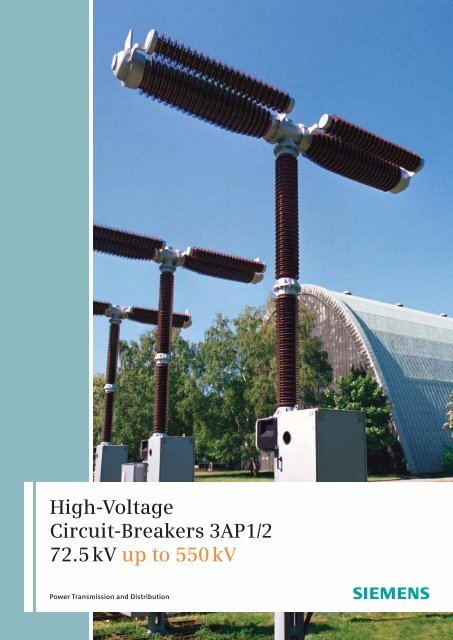
High-Voltage Circuit-Breakers 3AP1/2 72.5 kV up to 550 kV - Siemens
High-Voltage Circuit-Breakers 3AP1/2 72.5 kV up to 550 kV - Siemens
High-Voltage Circuit-Breakers 3AP1/2 72.5 kV up to 550 kV - Siemens

Create successful ePaper yourself
Turn your PDF publications into a flip-book with our unique Google optimized e-Paper software.
<strong>High</strong>-<strong>Voltage</strong><br />
<strong>Circuit</strong>-<strong>Breakers</strong> <strong>3AP1</strong>/2<br />
<strong>72.5</strong> <strong>kV</strong> <strong>up</strong> <strong>to</strong> <strong>550</strong> <strong>kV</strong><br />
Power Transmission and Distribution
The <strong>3AP1</strong>/2<br />
<strong>High</strong>-<strong>Voltage</strong> <strong>Circuit</strong>-<strong>Breakers</strong><br />
Now Applicable for <strong>550</strong> <strong>kV</strong><br />
Decades of our experience in high-voltage<br />
switching technology go in<strong>to</strong> the<br />
design and production of the <strong>3AP1</strong>/2<br />
circuit-breakers which set an international<br />
trend. We are a powerful partner<br />
for our cus<strong>to</strong>mers and a competent<br />
s<strong>up</strong>plier of attractive products and solutions<br />
at competitive prices with the<br />
high standard of quality that <strong>Siemens</strong><br />
is known for. We comply with our cus<strong>to</strong>mers’<br />
demands for reliability, safety<br />
and cost-effectiveness and serve them<br />
throughout the world. No matter what<br />
your application is, the <strong>3AP1</strong>/2 circuitbreakers<br />
provide the best solution for<br />
your requirements every time.<br />
Our standard is reliability and safety at<br />
all times<br />
The <strong>3AP1</strong>/2 circuit-breaker family is available<br />
for rated voltages from <strong>72.5</strong> <strong>kV</strong> <strong>up</strong><br />
<strong>to</strong> <strong>550</strong> <strong>kV</strong>. The latest development of our<br />
well established circuit-breakers completes<br />
our 3AP product range for rated<br />
voltages <strong>up</strong> <strong>to</strong> <strong>550</strong> <strong>kV</strong>. For the application<br />
of 362 <strong>kV</strong> <strong>to</strong> <strong>550</strong> <strong>kV</strong> the circuit-breakers<br />
can be equipped with optional closing<br />
resis<strong>to</strong>rs. The circuit-breakers feature approved<br />
technology and ensures efficient<br />
operation. Based on our well proven<br />
modular design, we manufacture all of<br />
the core components ourselves, which<br />
include the s<strong>to</strong>red-energy spring mechanism<br />
and the arc-assisted interr<strong>up</strong>ter unit.<br />
More than 50,000 3AP-circuit-breakers<br />
have been delivered <strong>to</strong> over 120 countries<br />
around the world in all climatic<br />
areas, proving on a daily basis the value<br />
and the reliability of the 3AP high-voltage<br />
switchgear. The <strong>3AP1</strong>/2 high-voltage<br />
circuit-breaker operates safely and is<br />
capable of withstanding high mechanical<br />
loads. Particularly strong porcelain<br />
insula<strong>to</strong>rs and a circuit-breaker design<br />
optimized by using the latest mathematical<br />
techniques, give it very high seismic<br />
stability whilst in operation enabling it<br />
<strong>to</strong> perform <strong>to</strong> its full potential during its<br />
entire service life.<br />
3AP2 FI 420 <strong>kV</strong><br />
Live-tank circuit-breaker<br />
in operation at a major<br />
power transmission and<br />
distribution company<br />
2
With <strong>High</strong>-<strong>Voltage</strong> <strong>Circuit</strong>-<strong>Breakers</strong><br />
from <strong>Siemens</strong> you are always on<br />
the Economically Safe Side<br />
Great demands for highest quality<br />
Our quality management system, certified<br />
in accordance with DIN EN ISO 9001,<br />
confirms that our quality always remains<br />
at the same high level. We carry out<br />
regular management reviews, internal<br />
audits in every department and the continuous<br />
development and maintenance<br />
of documentation for all processes. Most<br />
modern manufacturing technologies and<br />
investments in our worldwide production<br />
sites, assure reliable and long-lasting<br />
products and process quality according<br />
<strong>to</strong> <strong>Siemens</strong>’ well-proven high standards.<br />
The high quality, as well as excellent<br />
operating experience, is inherited by<br />
the 3AP series. The result is very high<br />
SF 6 tightness of our switchgear: The SF 6<br />
leakage rate is less than 0.5% per year.<br />
This not only increases reliability and<br />
decreases operating costs as a result of<br />
long maintenance intervals, but also has<br />
a positive impact on the environment, indicating<br />
our sense of responsibility.<br />
Our switchgear will fulfill your demands<br />
for low life-cycle-costs with highest availability<br />
and economical and continuous<br />
operation. We use strong materials under<br />
low mechanical loads in the construction<br />
of individual switchgear components,<br />
therefore maintenance is not needed for<br />
25 years or 10,000 operating cycles.<br />
By standardizing our internal processes<br />
and systematically implementing module<br />
strategies for our 3AP product series, we<br />
can offer minimal delivery times.<br />
<strong>3AP1</strong> FG 145 <strong>kV</strong> Live-tank circuit-breaker<br />
The results are low service and investment<br />
costs which provide our cus<strong>to</strong>mers<br />
competitive advantages worldwide,<br />
which equates <strong>to</strong> greater success for their<br />
own businesses.<br />
3
The Modular Design<br />
The self compression arc-quenching<br />
principle is applied in our 3AP circuitbreakers.<br />
The arc-assisted interr<strong>up</strong>ter unit of the<br />
3AP circuit-breaker utilises the energy of<br />
the arc during opening for an optimal arc<br />
quenching, allowing <strong>to</strong> reduce the operating<br />
energy <strong>to</strong> a minimum. Our circuitbreakers<br />
for the voltage range <strong>72.5</strong> <strong>kV</strong> <strong>up</strong><br />
<strong>to</strong> 300 <strong>kV</strong> have one interr<strong>up</strong>ter unit per<br />
pole and <strong>up</strong> <strong>to</strong> 245 <strong>kV</strong> the circuit-breakers<br />
are available with a common or a singlepole<br />
operating mechanism. 3AP highvoltage<br />
circuit-breakers from 362 <strong>kV</strong> <strong>up</strong> <strong>to</strong><br />
<strong>550</strong> <strong>kV</strong> are equipped with two interr<strong>up</strong>ter<br />
units per pole. For special technical requirements,<br />
e.g. increased TRV values,<br />
the breakers are available with four interr<strong>up</strong>ter<br />
units.<br />
The s<strong>to</strong>red-energy spring mechanism<br />
The compact design of this operating<br />
mechanism allows <strong>to</strong> place the s<strong>to</strong>red-energy<br />
spring mechanism within the control<br />
cubicle. The main components such as<br />
the interr<strong>up</strong>ter unit and the operating<br />
mechanism of our <strong>3AP1</strong>/2 high-voltage<br />
circuit-breakers, are identical <strong>to</strong> the ones<br />
in our 3AP deadtank circuit-breaker family.<br />
By applying this proven modular design<br />
we can fulfill the highest expectation with<br />
regard <strong>to</strong> availability, reliability, as well as<br />
economical performance. This results in<br />
continuously high cus<strong>to</strong>mer satisfaction.<br />
1<br />
2<br />
1<br />
2<br />
4,5<br />
3<br />
<strong>3AP1</strong> FG <strong>up</strong> <strong>to</strong> <strong>72.5</strong> <strong>kV</strong><br />
One interr<strong>up</strong>ter unit per pole.<br />
Laterally s<strong>to</strong>red-energy spring mechanism, circuit-breaker<br />
with common breaker base for three-pole operation<br />
3<br />
4,5<br />
<strong>3AP1</strong> FG <strong>up</strong> <strong>to</strong> 245 <strong>kV</strong><br />
One interr<strong>up</strong>ter unit per pole.<br />
S<strong>to</strong>red-energy spring mechanism, circuit-breaker<br />
with common breaker base for three-pole operation<br />
1<br />
2<br />
1<br />
6/7<br />
2<br />
4<br />
5<br />
3<br />
4<br />
5<br />
3<br />
<strong>3AP1</strong> FI <strong>up</strong> <strong>to</strong> 300 <strong>kV</strong><br />
One interr<strong>up</strong>ter unit per pole.<br />
S<strong>to</strong>red-energy spring mechanism, three-pole breaker with<br />
seperate breaker base for one or three-pole operation<br />
3AP2 FI <strong>up</strong> <strong>to</strong> <strong>550</strong> <strong>kV</strong><br />
Two respectively four interr<strong>up</strong>ter units per pole.<br />
S<strong>to</strong>red-energy spring mechanism, circuit-breaker<br />
with separate breaker base for one or three-pole operation<br />
3AP circuit-breakers are available in different designs<br />
1 Interr<strong>up</strong>ter unit<br />
2 Post insula<strong>to</strong>r<br />
3 Pillar<br />
4 Control cabinet<br />
5 Operating mechanism cubicle<br />
6 Grading capaci<strong>to</strong>r<br />
7 Closing resis<strong>to</strong>r (optional)<br />
4
The Quenching<br />
Principle<br />
6 5 2 4 3 1<br />
Closed position<br />
The conducting path<br />
The current conducting path of the interr<strong>up</strong>ter<br />
unit consists of the contact carrier<br />
(1), the base (6) and the moveable contact<br />
cylinder (5). In the closed position,<br />
the current flows via the main contact (2)<br />
and the contact cylinder (5).<br />
Breaking operating currents<br />
During the opening operation, the main<br />
contact (2) opens first, and the current<br />
commutates <strong>to</strong> the still closed arcing<br />
contact. During the further course of<br />
opening the arcing contact (3) opens and<br />
an arc is drawn between the contacts. At<br />
the same time, the contact cylinder (5)<br />
moves in<strong>to</strong> the base (6) and compresses<br />
the SF 6 gas located there. This gas compression<br />
creates a gas flow through the<br />
contact cylinder (5) and the nozzle (4) <strong>to</strong><br />
the arcing contact extinguishing the arc.<br />
Breaking fault currents<br />
In the event of interr<strong>up</strong>ting high shortcircuit<br />
breaking current, the SF 6 gas is<br />
heated <strong>up</strong> considerably at the arcing<br />
contact due <strong>to</strong> the energy of the arc. This<br />
leads <strong>to</strong> a pressure increase in the contact<br />
cylinder. During the further course of<br />
opening this increased pressure initiale a<br />
gas flow through the nozzle (4) extinguishing<br />
the arc. In this case, the arc energy<br />
is used <strong>to</strong> interr<strong>up</strong>t the fault circuit<br />
breaking current. This energy needs not<br />
<strong>to</strong> be provided by the<br />
operating mechanism.<br />
Opening: main contact in open position<br />
Opening: arcing contact in open position<br />
The interr<strong>up</strong>ter unit of the 3AP circuitbreaker<br />
is very efficient<br />
A fixed arcing contact is used for rated<br />
voltages <strong>up</strong> <strong>to</strong> 145 <strong>kV</strong>. This results in a<br />
reduced number of mechanical parts in<br />
the interr<strong>up</strong>ter unit.<br />
Open position<br />
1 Contact carrier<br />
2 Main contact<br />
3 Arcing contact<br />
4 Nozzle<br />
5 Contact cylinder<br />
6 Base<br />
5
The S<strong>to</strong>red-energy<br />
Spring Mechanism<br />
The advantages of the s<strong>to</strong>red-energy<br />
spring mechanism:<br />
Same principle for rated voltages from<br />
<strong>72.5</strong> <strong>up</strong> <strong>to</strong> <strong>550</strong> <strong>kV</strong><br />
<strong>High</strong> reliability thanks <strong>to</strong> low operating<br />
energy<br />
Simple principle of operation<br />
Controllable switching state at all<br />
times<br />
Low maintenance, economical and<br />
long lifetime<br />
Low environmental impact<br />
There are a number of advantages <strong>to</strong><br />
our s<strong>to</strong>red-energy spring mechanism<br />
Compact housing can be utilized by applying<br />
the most modern production<br />
techniques. Since the closing and opening<br />
springs are housed in the operating<br />
mechanism, a compact and sturdy structure<br />
is achieved.<br />
This design results in a small number<br />
of moving parts. The use of roller bearings<br />
and the maintenance-free spring<br />
mechanism are a prerequisite for decades<br />
of reliable operation. Proven design principles<br />
such as vibration-isolated latches<br />
and load-free isolation of the charging<br />
mechanism are retained.<br />
1<br />
2<br />
3<br />
4<br />
5<br />
8<br />
9<br />
10<br />
11<br />
12<br />
13<br />
6<br />
1 Trip coil CLOSE<br />
2 Cam plate<br />
3 Corner gear<br />
4 Connecting rod<br />
5 Connecting rod for closing spring<br />
6 Connecting rod for opening spring<br />
7 Closing spring<br />
8 Emergency hand crank<br />
9 Charging gear<br />
10 Charging shaft<br />
11 Roller lever<br />
12 Damper (for closing)<br />
13 Operating shaft<br />
14 Damper (for opening)<br />
15 Trip coil OPEN<br />
16 Drive mechanism housing<br />
17 Opening spring<br />
6<br />
7<br />
14<br />
15<br />
16<br />
17
The Control<br />
Control cabinet<br />
with the s<strong>to</strong>redenergy<br />
spring<br />
mechanism<br />
The control system includes all the secondary<br />
components required for operating<br />
the circuit-breaker, most of them<br />
are located in the control cabinet.<br />
The control, tripping, mo<strong>to</strong>r and heating<br />
power s<strong>up</strong>plies are, <strong>to</strong> a great<br />
extend, selectable. Depending on<br />
cus<strong>to</strong>mer requirements, two standard<br />
control variants are available.<br />
Basic variant<br />
The basic variant includes all control and<br />
moni<strong>to</strong>ring elements that are needed for<br />
operation of the circuit-breaker. In addition<br />
<strong>to</strong> the elementary actuation functions,<br />
it includes:<br />
19 auxiliary switch contacts<br />
(9 normally open, 9 normally closed,<br />
1 wiper contact)<br />
Switching operation counter<br />
Local actua<strong>to</strong>r<br />
Compact variant<br />
In addition <strong>to</strong> the basic variant, this variant<br />
includes:<br />
Spring moni<strong>to</strong>ring by mo<strong>to</strong>r run time<br />
moni<strong>to</strong>ring<br />
Heating moni<strong>to</strong>ring (current<br />
measuring relay)<br />
Light and socket with a<br />
common circuit-breaker<br />
Overvoltage attenuation<br />
Mo<strong>to</strong>r circuit-breaker<br />
Heating circuit-breaker<br />
Special features<br />
Above and beyond these two standard<br />
variants, a great number of further components<br />
and options are at our cus<strong>to</strong>mers’<br />
disposal. Every control configuration<br />
of a circuit-breaker can therefore be<br />
designed individually. All control components<br />
have been type-tested for use on<br />
our circuit-breakers and are all located in<br />
a weatherproof cubicle (IP 55 degree of<br />
protection). They are resistant <strong>to</strong> switching<br />
vibrations, and meet the requirements<br />
for electromagnetic compatibility<br />
(EMC).<br />
The circuit-breaker documentation includes<br />
the wiring diagram of the control<br />
configuration. This diagram comprises<br />
the following documents:<br />
Location diagram<br />
<strong>Circuit</strong> diagram<br />
Technical data equipment part list<br />
Connection diagram<br />
The circuit diagram documentation is bilingual<br />
in one common cus<strong>to</strong>mer specific<br />
language and in German.<br />
7
Quality<br />
Right from the Start<br />
3AP2 FI <strong>550</strong> <strong>kV</strong> Live-tank circuit-breaker<br />
in our high-voltage testing labora<strong>to</strong>ry<br />
Development<br />
The foundation for the quality of <strong>Siemens</strong><br />
high-voltage circuit-breakers is laid down<br />
right from the beginning of the development<br />
of a new product. Switching<br />
performance, high-voltage stability and<br />
performance under mechanical loads<br />
(wind and short circuits) and during an<br />
earthquake are simulated and optimized<br />
in the outline design phase using computer-aided<br />
calculations.<br />
The use of common parts and assembled<br />
units in a large number of breaker types<br />
such as live-tank, dead-tank, as well as in<br />
the GIS means the production of a large<br />
number of the same type of main components.<br />
Steady and regular quantities of<br />
produced units allow a continuous production<br />
process and ensure the highest<br />
quality standards. Statistic quality control<br />
is based on large quantities. This results<br />
in a higher achieved validity.<br />
All <strong>3AP1</strong>/2 circuit-breakers can be used in<br />
earthquake areas <strong>up</strong> <strong>to</strong> 0.5 g without<br />
additional fittings.<br />
Testing labora<strong>to</strong>ries<br />
Our Berlin circuit-breaker plant has the<br />
most modern testing labora<strong>to</strong>ries and offers<br />
all required facilities:<br />
Physics labora<strong>to</strong>ry<br />
<strong>High</strong>-voltage testing labora<strong>to</strong>ry<br />
Switching performance testing<br />
labora<strong>to</strong>ry<br />
Mechanical testing labora<strong>to</strong>ry<br />
Temperature rise testing labora<strong>to</strong>ry<br />
The testing labora<strong>to</strong>ries are certified by<br />
the German accreditation body<br />
Technik e.V. in accordance with DIN<br />
45001. With the society for electrical<br />
high-power tests (PEHLA), the testing<br />
labora<strong>to</strong>ries are part of the European network<br />
of independent testing organizations<br />
(STL). The <strong>3AP1</strong>/2 circuit-breakers are fully<br />
typetested in accordance with the new IEC<br />
62271-100 and ANSI-Standard.<br />
8
Routine testing<br />
The main components of the circuitbreakers<br />
are subjected <strong>to</strong> complete<br />
pre-acceptance testing before assembly.<br />
Based on this quality level, it is possible<br />
<strong>to</strong> confirm a leakage rate of less than<br />
0.5% per year for the circuit-breaker. Each<br />
circuit-breaker is completely assembled in<br />
the test bay. The product specific inputs<br />
for computer-assisted routine testing are<br />
imported au<strong>to</strong>matically from the order<br />
processing <strong>to</strong>ols. This ensures that in<br />
addition <strong>to</strong> the standard test procedure<br />
the fulfillment of every cus<strong>to</strong>mer requirement<br />
is checked before delivery.<br />
Routine testing is performed in accordance<br />
with the IEC- or ANSI-standards and<br />
it includes at least the following operations<br />
and measurements:<br />
Series of 100 mechanical switching cycles<br />
Switching time determination<br />
Release and mo<strong>to</strong>r currents<br />
Gas moni<strong>to</strong>ring<br />
Testing of control circuits in<br />
accordance with the circuit diagram<br />
<strong>Voltage</strong> drop of the main<br />
conducting path<br />
<strong>High</strong> voltage tests<br />
9
Installation –<br />
Simply Easy<br />
Installation and commissioning<br />
The circuit-breaker is dismantled in<strong>to</strong> few<br />
subassemblies for transportation. Transportation<br />
costs are minimized by using a<br />
very compact transport unit and by packing<br />
several circuit breakers <strong>to</strong>gether in<strong>to</strong><br />
one transportation unit.<br />
The subassemblies can be quickly assembled<br />
in<strong>to</strong> a complete circuit-breaker on<br />
site.<br />
The 3AP circuit breakers can be installed<br />
by a single installation fitter.<br />
No special <strong>to</strong>ols are required.<br />
Service offered by the manufacturer <strong>to</strong><br />
the opera<strong>to</strong>r<br />
Throughout the entire service life of<br />
the circuit-breaker we provide installation<br />
and commissioning and any other<br />
services on request.<br />
The first visual inspection of the circuitbreaker<br />
is not necessary within 12 years,<br />
and the first maintenance is recommended<br />
after 25 years.<br />
Depending on cus<strong>to</strong>mer requests, different<br />
diagnostic <strong>to</strong>ols can be offered.<br />
A worldwide 24 hours service is available,<br />
which immediately sends out service<br />
personnel and/or delivers spare parts as<br />
needed.<br />
3<br />
Install double<br />
interr<strong>up</strong>ter head<br />
2<br />
Install pole<br />
column A<br />
1<br />
Install pole<br />
column B<br />
3<br />
Install pole<br />
column C<br />
2<br />
Install post insula<strong>to</strong>r<br />
with operating rod<br />
1<br />
Install breaker base with<br />
operating mechanism<br />
and control cubicle<br />
<strong>3AP1</strong><br />
one working day<br />
3AP2<br />
two working days<br />
10
Technical Data<br />
Type <strong>3AP1</strong> 3AP2<br />
Rated voltage <strong>kV</strong> <strong>72.5</strong> 123 145 170 245 300 362 420 <strong>550</strong><br />
Number of interr<strong>up</strong>ter units per pole 1 2<br />
Rated power frequency withstand voltage/min <strong>kV</strong> 140 230 275 325 460 460 520 610 800<br />
Rated lightning impulse withstand voltage/min <strong>kV</strong> 325 <strong>550</strong> 650 750 1050 1050 1175 1425 1<strong>550</strong><br />
Rated switching impulse withstand voltage <strong>kV</strong> 850 950 1050 1175<br />
Rated normal current, <strong>up</strong> <strong>to</strong> A 4000 4000 4000 4000 4000 4000 5000 5000 5000<br />
Rated short-time withstand current (1 s - 3 s), <strong>up</strong> <strong>to</strong> kA (rms) 40 40 40 40 50 40 50 50 63<br />
Rated peak withstand current, <strong>up</strong> <strong>to</strong> kA (peak) 108 108 108 108 135 108 170 170 170<br />
Rated short-circuit breaking current, <strong>up</strong> <strong>to</strong> kA (rms) 40 40 40 40 50 40 63 63 63<br />
Rated short-circuit making current, <strong>up</strong> <strong>to</strong> kA (peak) 108 108 108 108 135 108 170 170 170<br />
Temperature range °C -30 or -40 ... +40 or +50<br />
Rated operating sequence<br />
0-0.3 s-CO-3 min-CO or CO-15 s-CO<br />
Rated break time 3 cycles 2 cycles<br />
Rated frequency Hz 50/60<br />
Type of drive mechanism<br />
S<strong>to</strong>red-energy spring mechanism<br />
Control voltage V DC 48...250<br />
Mo<strong>to</strong>r voltage V DC 48/60/110/125/220/250<br />
V AC<br />
120...240, 50 Hz; 120...280, 60 Hz<br />
Flashover distance phase/earth mm 700 1250 1250 1500 1900 2200 3400 3400 3800<br />
across open breaker mm 1200 1200 1200 1400 1900 2200 3200 3200 3800<br />
Min. creepage distance phase/earth mm 2248 3625 3625 4250 6125 7626 10375 1037513750<br />
across open breaker mm 3625 3625 3625 4250 6125 8575 10500 1050013750<br />
Dimensions height mm 3810 4360 4360 4810 6050 6870 6200 6200 7350<br />
width mm 3180 3880 3880 4180 6640 8235 8847 9847 13050<br />
depth mm 660 660 660 660 880 880 4380 4380 5050<br />
Phase spacing (min.) mm 1350 1700 1700 1850 2800 3600 4000 4500 6000<br />
<strong>Circuit</strong>-breaker mass kg 1350 1500 1500 1680 2940 3340 5370 5370 7160<br />
Maintenance after<br />
25 years<br />
Values in accordance with IEC, other values available on request<br />
11
For further Information<br />
Please fax this page<br />
<strong>to</strong> the following number:<br />
Fax +49 30/386-25867<br />
or send us an e-mail:<br />
circuit-breaker@<strong>Siemens</strong>.com<br />
Name<br />
Position<br />
Company<br />
Street<br />
Postcode/City/Country<br />
Phone/Fax<br />
Please send me more information on the following <strong>to</strong>pics:<br />
<strong>High</strong>-voltage circuit-breakers for outdoor installation<br />
Live-tank and dead-tank high-voltage circuit-breakers technology<br />
<strong>High</strong>-voltage compact switchgear <strong>3AP1</strong> DTC for 145 <strong>kV</strong><br />
Eliminate stress: Controlled switching of high-voltage circuit-breakers<br />
SF 6 in power engineering – acting responsibly<br />
Ruhrtal – Disconnec<strong>to</strong>rs and Earthing Switches<br />
Further copies of this brochure<br />
<strong>Siemens</strong> AG<br />
Power Transmission and Distribution<br />
<strong>High</strong> <strong>Voltage</strong> Division<br />
Nonnendammallee 14<br />
13629 Berlin<br />
Germany<br />
www.hv-circuit-breaker.com<br />
www.<strong>Siemens</strong>.com/ptd<br />
The information in this document contains<br />
general descriptions of the technical options<br />
available, which do not always have <strong>to</strong> be present<br />
in individual cases. The required features should<br />
therefore be specified in each individual case at<br />
the time of closing the contract.<br />
Subject <strong>to</strong> change without prior notice<br />
Order No. E50001-U113-A165- V3-7600<br />
Printed in Germany<br />
Dispo-Stelle 30000<br />
By. PA 03075.0<br />
www.<strong>Siemens</strong>.com


