Acroloc Machining Center Brochure - Sterling Machinery
Acroloc Machining Center Brochure - Sterling Machinery
Acroloc Machining Center Brochure - Sterling Machinery

Create successful ePaper yourself
Turn your PDF publications into a flip-book with our unique Google optimized e-Paper software.
I<br />
1. TOOL CHANGE<br />
Fast, simple and reliable tool change increases production and reduces downtime. The<br />
tool is placed under the spindle by programmed rotation of ti,e tobl disc. Downward<br />
motion of the spindle engages and locks the tool holder in place. Upward motion<br />
returns the tool holder to the 1001 disc.<br />
Up to 12 tools may be used. Tool chip-to-chip change time is 2 seconds. The ACROLOC<br />
Tool Holder is designed speci.fically for an automatic tool changer. It offers simplicity.<br />
/ SPINDLE<br />
rigidity, accuracy, reliability and high speed change. Each tool holder is a self-contained TOOL DISC<br />
mechanical locking mechanism. It is not subject to hydraulic, pneumatic, timing or<br />
adjustment problems.<br />
TOOL HOLDl<br />
2. SPINDLE SPEED CONTROL<br />
The spindle is powered by a 6 horsepower (@1750 rpm) dc motor. The speed of each tool may be infinitely adjusted from<br />
o to 4000 rpm. The tachometer indicates the actual spindle speed. The spindle speeds may be programmed on tape in<br />
direct rpm. The speeds may be changed without changing the tape by using 64 stored speed overrides.<br />
3. SPINDLE DRIVE AND BRAKE<br />
A two-speed pulley increases torque at low speed. Dynamic braking stops the spindle before tool change. The spindle<br />
turns on automatically.<br />
4. 3RD AXIS SPINDLE CONTROL<br />
The 3rd axis spindle control provides the Ultimate in flexibility. It permits limitless multi-step cutting. It enables the user<br />
to achieve the full benefit from numerical control by transferring the set·up time from the expensive machine tool to the<br />
inexpensive desk. It preserves the set·up for succeeding runs. Tapping is ach ieved by using a tension type tool holder and<br />
programming the appropriate speed and feed.<br />
Drill oscillation to break chips or remove ch ips from deep holes can be programmed to provide the most appropriate<br />
sequence.<br />
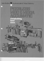
Broad Range Capabilities<br />
NO.6 TO 51160< OR IL L<br />
3500,RPM<br />
30"/MIN FE€ORATE<br />
\--L<br />
511'''-18 TAP f~------------------o-----~:---o--~---~-_---L<br />
CLEAN UP 0.1" STOC K REMOVAL<br />
100"/MIN FEEDRATE<br />
1/2" END MILL 3500 RPM<br />
(6·1/4 CU INCHES STOCK REMOVALl<br />
--~ ~\\<br />
T~<br />
CLAMP~O 0 0 \<br />
BOLTS<br />
"<br />
I<br />
!<br />
Ic--I-------=--I<br />
~<br />
------------------<br />
o o 0 o<br />
o<br />
o<br />
\,<br />
-- ----------- -------j<br />
1.0 DIA DRILL<br />
SLOT MILL SLOT MILL 700 RPM<br />
5/16" END MILL 3500 RPM 1/2" END MILL 3500 RPM 10"/MIN FEEDRATE<br />
20"/MIN FEEDRATE<br />
20"/MIN FEEDRATE<br />
MATERIAL: Aluminum<br />
(6·1/4 CU INCHES STOCK REMOVALl<br />
RUN TIME: 7 minutes<br />
\<br />
MATERIAL:<br />
OPERATIONS:<br />
RUN TIME:<br />
Aluminum<br />
(Round Stock)<br />
15 minutes<br />
6"·<br />
Mill, contour, bore<br />
drill and tap
5. SPINDLE<br />
Hard chrome plated spindle column is continuously supported over nine inches engagement. Opposing<br />
high precision taper roller bearings and ball bearing provide rigidity for milling. The taper roller bearings<br />
are thermal compensated. A lip type seal retains oil on spindle column.<br />
6. TABLE AND SADDLE<br />
The table is fabricated from s eel. The wear surfaces and entire top table surface are hardened and preci<br />
sion ground. The saddle consists of a meehanite iron casting.<br />
The base consists of hardened and ground alloy, turcited steel square ways. Dip rollers provide continuous<br />
lubrication for the table and saddle.<br />
7. BALL SCREWS<br />
Precision hardened and ground ball screws with anti-backlash nuts position the table and spindle.<br />
8. LUBRICATION<br />
An electric pump automatically and intermittently injects oil to the spindle, ball screws and sl ides. A bell<br />
warns the operator when the reservoir oil level is low.<br />
9. INTERFACE CONTROLS<br />
Plug-in circuit board. relays and components facilitate maintenance.<br />
Additional programmable relay sockets are included to permit future<br />
programmable options, such as pneumatic rotary indexers,<br />
10. HEAD ELEVATOR<br />
The head is raised and lowered electrically. Clamps on each side<br />
lock the head securel yin place.<br />
'rlOlli ,~<br />
'I(:I
o<br />
\,24] D1A)Ii 3,i1<br />
Ofrf' COUI\IT [R BORE<br />
--, 715<br />
1__3 ~,!>o<br />
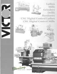
f ~~~~dL:~ CNC ROTARY<br />
1= TABLE OPTION<br />
.---------=~=-- , - - - --.,<br />
l~"<br />
I<br />
'j<br />
I<br />
10.5<br />
1-\-<br />
C;;;'/P,;ey -:5--.3 - Z-{ z~<br />
Specifications: ~<br />
• SPINDLE SPEED:<br />
• TABLE TRAVEL:<br />
• SPINDLE TRAVEL:<br />
• NUMBER OF TOOLS: __ 12<br />
• TOOL CHANGE TIME: _<br />
• WEIGHT:<br />
• HEAD TRAVEL: 16"<br />
38---,_'<br />
_d' I<br />
_· 1<br />
0 TO 4000 RPM<br />
32" X axis, 16" Y axis<br />
(300" per mi nute)<br />
8" (250" per minute)<br />
2 Secoods<br />
Approximat.ely 6000 pounds<br />
\ll'Mt·;.:.<br />
WWN<br />
~H1PPJN\.<br />
HlF"<br />
111I<br />
tlf"l<br />
o<br />
1<br />
Design Cone pt<br />
Ill"<br />
",<br />
~-.):i' <br />
''',wfl<br />
-I<br />
I<br />
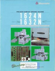
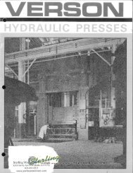
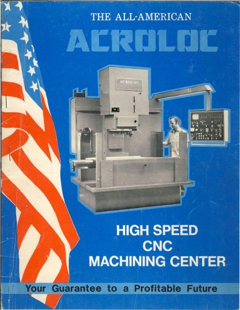
The ACROLOC is not a retrofit. It was designed in its entirety as a high speed <strong>Machining</strong> <strong>Center</strong>. All slides and<br />
moving parts are constructed for continuous opel'ation with minimum wear. Long guides in the X and Y axes provide<br />
excellent stability and eliminate table sag as experienced on milling machine frames.<br />
Every ACROLOC feature was specifically designed to utilize and maximize the latest developments in numerical<br />
control, variable speed motors, cutting tools, and coolants.<br />
Full CNC Capabirty<br />
The McDonnell Douglas ACTRIONI'O! Control built into the machine provides all the advantages of reliClbility, flexi- ~<br />
bil ity, and simplicity inherent in microcomputer numerical control systems. Full CNC capabil ity includes three-axis<br />
simultaneous contouring with optional fourth axis. The built,in control means less installation time and floor<br />
space requ ired.<br />
In Summary<br />
The ACROLOC utilizes the full advantage of nqmerical control. It is fast, flexible, simpl.e and reliable, and moderately<br />
priced. It provides good stock removal for mill ing; rapid tool changes for drill ing, ream ing, tapping, and boring.<br />
We would appreciate the chance to prove this to you.<br />
ACROLOC ~."<br />
f.<br />
__ t"" j.,i·'ii-I'·)<br />
13454 SOUTH WESTERN AVE.<br />
GARDENA. CA. 90249<br />
,<br />
(213) 323-2128<br />
-,