Matrix Switches Section - JFW Industries
Matrix Switches Section - JFW Industries
Matrix Switches Section - JFW Industries

Create successful ePaper yourself
Turn your PDF publications into a flip-book with our unique Google optimized e-Paper software.
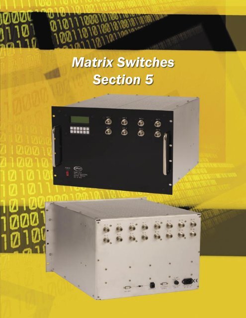
<strong>Matrix</strong> <strong>Switches</strong><br />
<strong>Section</strong> 5
<strong>Matrix</strong> <strong>Switches</strong><br />
Model Number Index<br />
Please add connector type to the end of part number to complete model number (Example: 50MS-193 N).<br />
Blocking <strong>Matrix</strong> <strong>Switches</strong><br />
Model Number Impedance Confi guration Frequency Range Control Page<br />
50MS-193 50 Ohm 2 X 4 Blocking DC-500 MHz Ethernet/RS-232 5-4<br />
50MS-211 50 Ohm 4 x 8 Blocking DC-6000 MHz Ethernet/RS-232 5-6<br />
50MS-232 50 Ohm 12 x 4 Blocking DC-4000 MHz Ethernet/RS-232 5-8<br />
Non-Blocking <strong>Matrix</strong> <strong>Switches</strong><br />
Model Number Impedance Confi guration Frequency Range Control Page<br />
50MS-192 50 Ohm 24 X 3 Non-Blocking 800-2400 MHz Ethernet/RS-232 5-16<br />
50MS-216 50 Ohm 4 x 8 Non-Blocking 2000-3000 MHz Ethernet/RS-232 5-10<br />
50MS-220 50 Ohm 16 x 8 Non-Blocking 800-2200 MHz Ethernet/RS-232 5-12<br />
50MS-225 50 Ohm 12 x 10 Non-Blocking 100-1500 MHz Ethernet/RS-232 5-14<br />
Custom Capabilities with no NREs<br />
This section of the catalog showcases some standard blocking matrix switches. However, most of <strong>JFW</strong>’s test system<br />
business involves custom designed models. <strong>JFW</strong> does not charge NRE’s for custom models. We encourage you<br />
to email us your requirement (sales@jfwindustries.com). We will respond with a ROM (rough order of magnitude)<br />
quote in 1-2 days. Please include a block diagram with your request if you already have an idea of exactly what you<br />
require.<br />
Blocking Pros<br />
Lower insertion loss<br />
Higher port to port isolation<br />
Non-Blocking Pros<br />
All input ports available to all output ports all the time<br />
Blocking Cons<br />
Input ports not available to multiple output ports<br />
Non-Blocking Cons<br />
Higher insertion loss<br />
Lower port to port isolation<br />
Available Options<br />
- GPIB, RS-232, or Ethernet control - Frequency ranges from DC-18 GHz<br />
- Keypad & LCD display for manual control - Various RF connector options (BNC, TNC, SMA, N, etc.)<br />
- 19”, 23”, 24” rack enclosures - 50 Ohm and 75 Ohm impedance<br />
- Benchtop enclosures - Dual redundant power supplies<br />
5-2
3 X 3 Blocking <strong>Matrix</strong> Example<br />
The below schematic shows an example of a 3 X 3 blocking matrix. It is built with switches on both the<br />
input ports and output ports. Each output port can only be connected to a single input port. Also, each<br />
input port can only be connected to a single output port. This confi guration maximizes the isolation<br />
between ports and minimizes the insertion loss of the system. If you do require an input port be connected<br />
to multiple output ports at the same time, then you need to use a Non-Blocking <strong>Matrix</strong> Switch which is<br />
detailed in the next example.<br />
Both schematics on this page show some bolded connections. These bolded lines help to show the<br />
difference between the two types of matrix switch. For a blocking matrix switch, input #1 can only be<br />
connected to a single output. On the nonblocking matrix switch, input #1 can be connected to all outputs<br />
at the same time.<br />
3 X 3 Non-Blocking <strong>Matrix</strong> Example<br />
The below schematic shows an example of a 3 X 3 non-blocking matrix. It is built with power dividers on<br />
the inputs and switches on the outputs. Each input signal is split to all output switches. This confi guration<br />
provides greater switching fl exibility because you can have multiple output ports connected to the same<br />
input port at the same time. The power dividers help provide more possible connection confi gurations,<br />
but the power dividers also increase the insertion loss of the system.<br />
Both schematics on this page show some bolded connections. These bolded lines help to show the<br />
difference between the two types of matrix switch. For a blocking matrix switch, input #1 can only be<br />
connected to a single output. On the nonblocking matrix switch, input #1 can be connected to all outputs<br />
at the same time.<br />
5-3
<strong>Matrix</strong> Switch<br />
Model Configuration Impedance Frequency Range VSWR<br />
(maximum)<br />
Input Power<br />
(average)<br />
50MS-193<br />
2 x 4 Blocking <strong>Matrix</strong> Switch<br />
(all switches)<br />
50 Ohms DC-500 MHz 1.10:1 100 Watts (cold switched)<br />
Control<br />
Insertion Loss<br />
(maximum)<br />
Isolation<br />
(minimum)<br />
Switching Speed<br />
(typical)<br />
Ethernet(10/100)/RS-232/Manual<br />
0.5 dB<br />
Radio to Radio: 90 dB minimum<br />
Antenna to Antenna: 90 dB minimum<br />
20 milliseconds (after command is processed)<br />
(3 milliseconds typical processing time)<br />
AC Supply RF Connectors Operating Temperature Remote Commands<br />
100-240 VAC @ 47-63 Hz SMA or N female 0ºC to +50ºC Set Path, Read Input, Read Output, Identification, Change Baud Rate<br />
See next page for block diagram.<br />
5-4
<strong>Matrix</strong> <strong>Switches</strong><br />
<strong>JFW</strong> Model 50MS-193 Block Diagram<br />
5-5
<strong>Matrix</strong> Switch<br />
Model Configuration Impedance Frequency Range VSWR<br />
(maximum)<br />
50MS-211<br />
4 x 8 Blocking <strong>Matrix</strong><br />
(all switches)<br />
Input Power<br />
(average)<br />
Control<br />
50 Ohms DC-6000 MHz 1.5:1 1 Watt Ethernet(10/100)/RS-232/Manual<br />
Insertion Loss<br />
(maximum)<br />
1 dB DC-2500 MHz<br />
2 dB 2500-6000 MHz<br />
Isolation<br />
(minimum)<br />
70 dB DC-4000 MHz<br />
65 dB 4000-6000 MHz<br />
Switching Speed<br />
20 milliseconds (after command is processed)<br />
(3 milliseconds typical processing time)<br />
AC Supply RF Connectors Operating<br />
Temperature<br />
Remote Commands<br />
See next page for block diagram.<br />
5-6
<strong>Matrix</strong> <strong>Switches</strong><br />
<strong>JFW</strong> Model 50MS-211 Block Diagram<br />
5-7
<strong>Matrix</strong> Switch<br />
Model Configuration Impedance Frequency Range VSWR<br />
(maximum)<br />
50MS-232<br />
12 x 4 Blocking <strong>Matrix</strong><br />
(all switches)<br />
50 Ohms DC-4000 MHz<br />
1.5:1 DC-2000 MHz<br />
1.7:1 2000-4000 MHz<br />
Input Power<br />
(average)<br />
1 Watt<br />
Control<br />
Insertion Loss<br />
(maximum)<br />
Isolation<br />
(minimum)<br />
Switching Speed<br />
Ethernet(10/100)/RS-232/Manual<br />
2.5 dB<br />
2.1 dB typical @ 4000 MHz<br />
Input to Input: 70 dB<br />
Input to Output: 70 dB<br />
Output to Output: 70 dB<br />
20 milliseconds (after command is processed)<br />
(3 milliseconds typical processing time)<br />
AC Supply RF Connectors Operating Temperature Remote Commands<br />
100-240 VAC at 47-63 Hz SMA female 0ºC to +50ºC<br />
Set Path, Read Input, Read Output, Identification, Change Baud<br />
Rate<br />
See next page for block diagram.<br />
5-8
<strong>Matrix</strong> <strong>Switches</strong><br />
<strong>JFW</strong> Model 50MS-232 Block Diagram<br />
5-9
<strong>Matrix</strong> Switch<br />
Model Configuration Impedance Frequency Range VSWR Input Power<br />
(average)<br />
50MS-216 4 x 8 Non-Blocking <strong>Matrix</strong> 50 Ohms 2-3 GHz<br />
1.5:1 typical<br />
1.7:1 maximum<br />
Control<br />
1 Watt Ethernet(10/100)/RS-232/Manual<br />
Insertion Loss<br />
(nominal)<br />
12 dB<br />
Isolation<br />
(minimum)<br />
Input to Output - 70 dB<br />
Output to Output - 70 dB<br />
Output to Output switched to separate inputs - 70 dB<br />
Output to Output switched to same input - 20 dB<br />
Switching Speed<br />
25 milliseconds (after command is processed)<br />
(3 milliseconds typical processing time)<br />
AC Supply<br />
100-240 VAC at 47-63 Hz<br />
RF Connector Operating Temperature Remote Commands<br />
SMA female 0ºC to +50ºC Set Output, Read Output, Identification, Change Baud Rate<br />
See next page for block diagram.<br />
5-10
<strong>Matrix</strong> <strong>Switches</strong><br />
<strong>JFW</strong> Model 50MS-216 Block Diagram<br />
5-11
<strong>Matrix</strong> Switch<br />
Model Configuration Impedance Frequency Range VSWR Input Power<br />
(average)<br />
50MS-220 16 x 8 Non-Blocking <strong>Matrix</strong> 50 Ohms 800-2200 MHz<br />
1.7:1 maximum<br />
1.5:1 typical<br />
Control<br />
1 Watt Ethernet(10/100)/RS-232/Manual<br />
Insertion Loss<br />
(nominal)<br />
15 dB @ 2200 MHz<br />
Isolation<br />
(minimum)<br />
Input to Input 68 dB<br />
Input to Output 50 dB<br />
Output to Output 28 dB<br />
Switching Speed<br />
(typical)<br />
20 microseconds (after command is processed)<br />
(3 milliseconds typical processing time)<br />
AC Supply<br />
100-240 VAC @ 47-63 Hz<br />
RF Connector Operating Temperature Remote Commands<br />
N female 0ºC to +50ºC Set Path, Read Input, Read Output, Identification, Change Baud Rate<br />
See next page for block diagram.<br />
5-12
<strong>Matrix</strong> <strong>Switches</strong><br />
<strong>JFW</strong> Model 50MS-220 Block Diagram<br />
5-13
<strong>Matrix</strong> Switch<br />
Model Configuration Impedance Frequency Range VSWR Input Power<br />
(average)<br />
50MS-225<br />
12 x 10 Non-<br />
Blocking <strong>Matrix</strong><br />
50 Ohms 100-1500 MHz<br />
1.4:1 typical<br />
1.6:1 maximum<br />
Control<br />
1 Watt Ethernet(10/100)/Manual<br />
Insertion Loss<br />
(nominal)<br />
Isolation<br />
(minimum)<br />
Switching Speed<br />
(typical)<br />
AC Supply<br />
20 dB @ 100 MHz<br />
22 dB @ 1500 MHz<br />
Input to Input 60 dB<br />
Input to Output 60 dB<br />
Output to Output<br />
(Different Inputs)60 dB<br />
Output to Output<br />
(Same Input) 20 dB<br />
20 microseconds (after command processed)<br />
(3 milliseconds typical processing time)<br />
100-240 VAC @ 47-63 Hz<br />
RF Connector Operating Temperature Remote Commands<br />
N female 0ºC to +50ºC Set Output, Read Output, Identification<br />
See next page for block diagram.<br />
5-14
<strong>Matrix</strong> <strong>Switches</strong><br />
<strong>JFW</strong> Model 50MS-225 Block Diagram<br />
5-15
<strong>Matrix</strong> <strong>Switches</strong><br />
Model Configuration Impedance Frequency Range VSWR Input Power<br />
(average)<br />
50MS-192 24 x 3 Non-Blocking <strong>Matrix</strong> 50 Ohms 800-2400 MHz<br />
1.4:1 typical<br />
1.6:1 maximum<br />
+20 dBm<br />
Control Insertion Loss Isolation<br />
(minimum)<br />
Ethernet(10/100)/RS-232<br />
22 dB typical 800-1000 MHz<br />
24 dB maximum 800-1000 MHz<br />
26 dB typical 1000-2400 MHz<br />
28 dB maximum1000-2400 MHz<br />
Input to Input - 20 dB<br />
Input to Output - 50 dB<br />
Output to Output - 50 dB<br />
Switching Speed<br />
(typical)<br />
100 microseconds (after command is processed)<br />
(3 milliseconds typical processing time)<br />
Attenuation Range Attenuation Accuracy AC Supply RF Connectors Operating Temperature<br />
0-63 dB x 1 dB<br />
±0.4 dB or 2% 100-240 VAC at 47-63 Hz N female -55ºC to +85ºC<br />
Remote Commands<br />
Set Input, Read Input, Set Attenuator, Read Attenuator, Identification<br />
See next page for block diagram.<br />
5-16
<strong>Matrix</strong> <strong>Switches</strong><br />
<strong>JFW</strong> Model 50MS-192 Block Diagram<br />
5-17