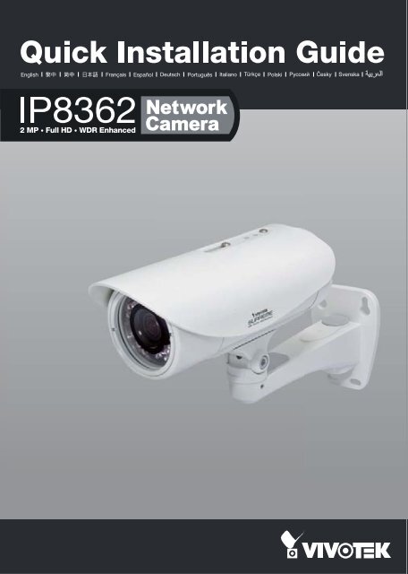
Vivotek-IP8362 Quick Installation Guide
Vivotek-IP8362 Quick Installation Guide
Vivotek-IP8362 Quick Installation Guide

You also want an ePaper? Increase the reach of your titles
YUMPU automatically turns print PDFs into web optimized ePapers that Google loves.
English<br />
Warning Before <strong>Installation</strong><br />
Power off the Network Camera as<br />
soon as smoke or unusual odors are<br />
detected.<br />
Refer to your user's manual for the<br />
operating temperature.<br />
Contact your distributor in the<br />
event of occurrence.<br />
Do not place the Network Camera on<br />
unsteady surfaces.<br />
Do not touch the Network Camera<br />
during a lightning storm.<br />
Do not insert sharp or tiny objects<br />
into the Network Camera.<br />
Do not drop the Network Camera.<br />
EN-1<br />
P/N: 625016600G
1<br />
Package Contents<br />
<strong>IP8362</strong><br />
Alignment Sticker<br />
Sun Shield<br />
Wrench / Double-sided Tape / Screws<br />
Waterproof Connector<br />
Wall Mount Bracket<br />
<strong>Quick</strong> <strong>Installation</strong> <strong>Guide</strong> /<br />
Warranty Card<br />
Moisture Absorber<br />
Software CD<br />
EN-2
English<br />
2<br />
Physical Description<br />
Light Sensor<br />
IR LED<br />
Lens<br />
Focus Controller<br />
Reset Button<br />
Zoom Controller<br />
General I/O<br />
Terminal Block<br />
SD/SDHC Card Slot<br />
When inserting an SD/SDHC card,<br />
note the orientation of the contacts.<br />
Ethernet 10/100<br />
RJ45 Plug<br />
EN-3
3<br />
Hardware <strong>Installation</strong><br />
1. Attach the alignment sticker to the wall. Drill three holes into the wall. Then hammer the supplied<br />
plastic anchors into the holes and secure the plate with supplied screws.<br />
2. Feed the cables through the front opening of the wall mount bracket.<br />
3. Hang the wall mount bracket on the plate.<br />
4. Fix the Network Camera on the wall mount bracket with two screws on both sides.<br />
5. Secure the wall mount bracket with the supplied screws.<br />
6. Adjust the angle of the wall mount bracket to aim at the shooting area.<br />
1<br />
2<br />
3<br />
4<br />
6<br />
5<br />
4<br />
5<br />
6<br />
The supplied L-type hex key wrenches<br />
are exclusively designed to match each<br />
screw. In case you will need to adjust the<br />
lens later, do not discard the wrenches.<br />
EN-4
POWER CO LISION<br />
1 2 3 4 5<br />
LINK<br />
RECEIVE<br />
PARTITION<br />
English<br />
4<br />
Network Deployment<br />
Power over Ethernet (PoE)<br />
Using a PoE-enabled switch<br />
The Network Camera is PoE-compliant, allowing transmission of power and data via a single<br />
Ethernet cable. Follow the below illustration to connect the Network Camera to a PoE-enabled<br />
switch via Ethernet cable.<br />
Waterproof Connector<br />
Waterproof Connection<br />
PoE Switch<br />
Connect the camera's RJ45 connector through a waterproof cable gland, and to another Ethernet<br />
cable at the installation site. Wrap the rubber seal around Ethernet cables and squeeze it into the<br />
claws to prevent moisture. Make sure the components are tightly fastened.<br />
RJ45 Female/Famale<br />
Feed-through<br />
Rubber Seal<br />
Seal Nut<br />
From Camera<br />
RJ45<br />
Body w/ Claws<br />
To LAN/WAN<br />
EN-5
5<br />
Assigning an IP Address<br />
1. Install "<strong>Installation</strong> Wizard 2" from the Software Utility directory on the software CD.<br />
2. The program will conduct an analysis of your network environment. After your network<br />
is analyzed, please click on the "Next" button to continue the program.<br />
IW2<br />
<strong>Installation</strong><br />
Wizard 2<br />
3. The program will search for VIVOTEK Video Receivers, Video Servers, and Network<br />
Cameras on the same LAN.<br />
4. After searching, the main installer window will pop up. Click on the MAC that matches<br />
the one on the product label to connect to the Network Camera via Internet Explorer.<br />
Network Camera<br />
Model No: <strong>IP8362</strong> R o HS<br />
MAC:0002D1730202<br />
This device complies with part 15 of the FCC rules. Operation is subject to the following two conditions:<br />
(1)This device may not cause harmful interference, and<br />
(2) this device must accept any interference received, including interference that may cause undesired operation.<br />
Pat. 6,930,709<br />
Made in Taiwan<br />
00-02-D1-73-02-02 192.168.5.151 <strong>IP8362</strong><br />
0002D1730202<br />
EN-6
English<br />
6<br />
Ready to Use<br />
1. Access the Network Camera from the LAN.<br />
2. Retrieve live video through a web browser or recording software.<br />
For further setup, please refer to the user's manual on the software CD.<br />
3. Unscrew the zoom controller to adjust the<br />
zoom factor. Upon completion, tighten the<br />
zoom controller.<br />
4. Unscrew the focus controller to adjust the<br />
focus range. Upon completion, tighten the<br />
focus controller.<br />
N<br />
T<br />
3<br />
4<br />
∞<br />
W<br />
EN-7
5. Tighten the lens cover.<br />
6. Replace the moisture absorber with a new one if you open the back cover during the<br />
installation procedure.<br />
5<br />
6<br />
Please tear down the aluminum foil vacuum<br />
bag and take out the moisture absorber,<br />
then attach the moisture absorber with the<br />
supplied double-sided tape.<br />
Note<br />
If you want to use the supplied sun shield for outdoor environments, please follow the steps below to<br />
install:<br />
1. Tighten the supplied two screws.<br />
2. Attach the supplied sun shield to the Network Camera and slide it to the desired position.<br />
3. Fix the sun shield with the supplied two screws.<br />
1 2<br />
3<br />
EN-8