

Ground Fault Relays & Monitors - of downloads
Ground Fault Relays & Monitors - of downloads
Ground Fault Relays & Monitors - of downloads

You also want an ePaper? Increase the reach of your titles
YUMPU automatically turns print PDFs into web optimized ePapers that Google loves.
July 2008<br />
<strong>Ground</strong> <strong>Fault</strong> <strong>Relays</strong> & <strong>Monitors</strong><br />
I-1<br />
<strong>Ground</strong> <strong>Fault</strong> <strong>Relays</strong><br />
& <strong>Monitors</strong><br />
Contents<br />
Description<br />
Digital <strong>Ground</strong> <strong>Fault</strong> <strong>Relays</strong><br />
Product Description . . . . . . . . . . . . . . . . . . . . . . . . . . . . . . . . . . . . . . . . . . . I-2<br />
Application Description . . . . . . . . . . . . . . . . . . . . . . . . . . . . . . . . . . . . . . . . I-2<br />
Features. . . . . . . . . . . . . . . . . . . . . . . . . . . . . . . . . . . . . . . . . . . . . . . . . . . . . I-2<br />
Technical Data. . . . . . . . . . . . . . . . . . . . . . . . . . . . . . . . . . . . . . . . . . . . . . . . I-3<br />
Standards & Certifications. . . . . . . . . . . . . . . . . . . . . . . . . . . . . . . . . . . . . . I-3<br />
Factory Options . . . . . . . . . . . . . . . . . . . . . . . . . . . . . . . . . . . . . . . . . . . . . . I-3<br />
Accessories . . . . . . . . . . . . . . . . . . . . . . . . . . . . . . . . . . . . . . . . . . . . . . . . . . I-3<br />
Product Selection . . . . . . . . . . . . . . . . . . . . . . . . . . . . . . . . . . . . . . . . . . . . . I-4<br />
Typical Connection Diagrams . . . . . . . . . . . . . . . . . . . . . . . . . . . . . . . . . . . I-5<br />
Dimensions . . . . . . . . . . . . . . . . . . . . . . . . . . . . . . . . . . . . . . . . . . . . . . . . . . I-7<br />
Digital <strong>Ground</strong> <strong>Fault</strong> <strong>Monitors</strong> . . . . . . . . . . . . . . . . . . . . . . . . . . . . . . . . . . . . . I-9<br />
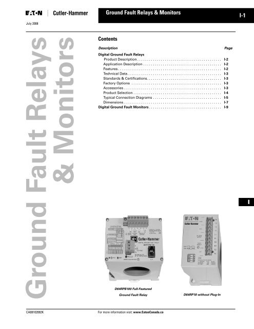
D64RPB100 Full-Featured<br />
<strong>Ground</strong> <strong>Fault</strong> Relay<br />
D64RP18 without Plug-In<br />
Page<br />
I<br />
CA08102002K<br />
For more information visit: www.EatonCanada.ca
I-2<br />
<strong>Ground</strong> <strong>Fault</strong> <strong>Relays</strong> and <strong>Monitors</strong><br />
D64R Series, Digital <strong>Ground</strong> <strong>Fault</strong> <strong>Relays</strong><br />
July 2008<br />
D64R Series — Digital<br />
<strong>Ground</strong> <strong>Fault</strong> <strong>Relays</strong><br />
capacitance-to-ground effect <strong>of</strong> phase<br />
conductors in a system and will vary<br />
depending on:<br />
■ External CT supervision (on<br />
D64RPB30 model only). A detected<br />
open or short circuit will cause a trip<br />
■ the overall length <strong>of</strong> the cables<br />
■ the types <strong>of</strong> loads<br />
■ the quality <strong>of</strong> the insulation on the<br />
phase conductors<br />
■ the surrounding equipment grounding,<br />
cable trays, junction boxes, etc.<br />
■ the type and size <strong>of</strong> transformer<br />
A “rule-<strong>of</strong>-thumb” for systems 600V and<br />
lower: the “charging” current is 0.5A per<br />
1000 kVA <strong>of</strong> transformer capacity.<br />
■ Tamperpro<strong>of</strong> DIP switches (on<br />
D64RPB30 model only). Prevents<br />
unauthorized changes to DIP switch<br />
settings<br />
In the failsafe mode, the relay is energized<br />
when control voltage is applied<br />
and will trip when either:<br />
I<br />
D64RPB100 – Digital <strong>Ground</strong><br />
<strong>Fault</strong> Relay with Built-In Current<br />
Sensor or Zero-Sequence CT<br />
Product Description<br />
The new D64R digital ground fault<br />
relays are microprocessor-based and<br />
replace the previous generation <strong>of</strong><br />
analogue-based devices.<br />
Microprocessor-based D64R GFRs<br />
combine more selectable features into<br />
a single model, which makes easier<br />
model selection and reduces spares<br />
inventory requirements.<br />
These devices are designed to provide<br />
reliable detection <strong>of</strong> ground fault conditions<br />
on three-phase AC resistance<br />
grounded or solidly grounded electrical<br />
distribution systems.<br />
D64RPB30 – Compact Full-Featured<br />
<strong>Ground</strong> <strong>Fault</strong> Relay<br />
Application Description<br />
D64R ground fault relays feature adjustable<br />
trip settings for both trip current<br />
and trip time. This allows the user to set<br />
the ground fault trip current just above<br />
the “charging” current <strong>of</strong> the system.<br />
This prevents nuisance tripping and<br />
provides meaningful protection <strong>of</strong> additional<br />
ground fault leakage currents.<br />
Every system has a “charging” current<br />
that can cause nuisance tripping<br />
if the trip current is set too low. The<br />
“charging” current is caused by the<br />
Features<br />
Standard Models<br />
■ Built-in current sensor (zero<br />
sequence CT)<br />
■ Run and trip indicating LEDs<br />
■ Built-in harmonic filtering for variable<br />
frequency drives or standard 50/60<br />
Hz applications (see Table I-1 for frequency<br />
response range)<br />
■ DIN rail or panel mounting<br />
■ Rugged epoxy encapsulated<br />
construction<br />
■ Pull-apart terminal block connectors<br />
■ Form “Z” (4 terminal) NO and NC<br />
output contacts, 5 Amps at 250V AC<br />
■ Pulsed (trip) auto reset mode<br />
The pulsed (trip) auto reset mode is<br />
designed for applications where the<br />
output relay is operating a shunt trip<br />
device. The D64R relay resets automatically,<br />
three seconds after the ground<br />
fault current is interrupted by the tripping<br />
action <strong>of</strong> the circuit breaker. This<br />
opens the output contact wired to the<br />
shunt trip coil and prevents damage to<br />
the internal mechanism <strong>of</strong> the circuit<br />
breaker in the event that the operator<br />
tries to reset the circuit breaker.<br />
■ Suitable for use on 600V systems —<br />
may be applied on higher voltages<br />
by using separate CTs with power<br />
conductors insulated for the system<br />
voltage<br />
■ Built-in test circuitry — no external<br />
power or additional wiring is necessary<br />
— tests trip time and current<br />
settings<br />
■ Communications port (standard<br />
RJ-10 jack) for connection to<br />
optional remote display (D64D1)<br />
and door mounted units (on<br />
D64RPB100 models only)<br />
■ Failsafe selectable mode (on<br />
D64RPB30 and D64RPB100 models<br />
only)<br />
■ a ground fault trip is detected or,<br />
■ there is a loss <strong>of</strong> control power.<br />
Service Protection Models<br />
■ Service protection models require<br />
C311CT 10,000:1 ratio CTs<br />
■ Trip current range <strong>of</strong> 50 to 1200A<br />
■ Green LED indicates “Power On”<br />
■ Circuit breaker toggle position<br />
indicates “Normal” or “Tripped”<br />
condition<br />
■ Form “C” (3 terminal) NO-NC output<br />
contacts, 3 Amps at 250V AC<br />
■ Frequency response range <strong>of</strong> 40 to<br />
200 Hz<br />
■ Zone interlocking feature with green<br />
LED to indicate “Grading Input<br />
Active” and DIP switch array for<br />
zone grading backup delay and block<br />
signal override (on D64RPBH15<br />
model only)<br />
■ Test button to invoke test at 20A trip<br />
current — tests external CT, electronics<br />
and circuit breaker trip<br />
■ Failsafe selectable mode (see above<br />
for description)<br />
■ Inhibit selectable mode — this<br />
allows the relay to differentiate<br />
between normal ground fault trip<br />
levels and short circuit conditions<br />
The trip inhibit function is useful when<br />
the relay is being used to trip a contactor<br />
or motor starter on a solidly<br />
grounded system. Under a bolted fault<br />
condition, the relay would trip and<br />
could cause the contactor or motor<br />
starter to interrupt the high fault current<br />
with harmful results. By inhibiting the<br />
trip, the ground fault relay will not trip<br />
on bolted faults and will allow the<br />
upstream protective device to clear the<br />
fault instead.<br />
■ Through-the-door or rear panel<br />
mounting<br />
For more information visit: www.EatonCanada.ca<br />
CA08102002K
July 2008<br />
<strong>Ground</strong> <strong>Fault</strong> <strong>Relays</strong> and <strong>Monitors</strong><br />
D64R Series, Digital <strong>Ground</strong> <strong>Fault</strong> <strong>Relays</strong><br />
I-3<br />
Technical Data and Specifications<br />
Table I-1. Technical Data Specifications<br />
Catalogue<br />
Number<br />
D64RP18<br />
D64RPB30<br />
D64RPB100<br />
With Zone interlocking feature.<br />
Standards and Certifications<br />
■ UL 1053<br />
❑ <strong>Ground</strong> <strong>Fault</strong> Sensing and Relaying Equipment, Class 1<br />
(UL File # E195341)<br />
■ CSA C22.2 No. 144-M91<br />
❑ <strong>Ground</strong> <strong>Fault</strong> Circuit Interrupters (CSA File # 700103)<br />
■ CE Mark — Declaration <strong>of</strong> Conformity<br />
■ IEC 60755<br />
❑ General Requirements for residual current operated<br />
protective devices<br />
■ EN 50081-1<br />
❑ Electromagnetic compatibility (radiated emission),<br />
“household” directive<br />
D64R ground fault relays are UL listed as Class 1 devices<br />
designed to protect electrical equipment against extensive<br />
damage from arcing ground faults.<br />
Factory Options<br />
Control<br />
Power<br />
(Volts)<br />
24 – 240V AC/DC<br />
Non-isolated<br />
24 – 240V AC/DC<br />
Non-isolated<br />
24 – 240V AC/DC<br />
Isolated<br />
Frequency<br />
Response<br />
(Hz)<br />
Trip Current<br />
Range<br />
■ Other ranges <strong>of</strong> trip currents and times<br />
■ Fixed trip current and times<br />
■ Other control voltages<br />
■ Custom packaging for volume OEM requirements<br />
■ Separate outputs for alarming vs trip<br />
■ <strong>Relays</strong> for neutral grounding resistance monitoring<br />
■ <strong>Relays</strong> for ground fault detection on DC power systems<br />
■ Other sizes <strong>of</strong> current transformers<br />
Trip Time<br />
Delay Range<br />
Built-In<br />
Current<br />
Sensor<br />
Accessories<br />
External Current<br />
Transformer<br />
Test/Reset<br />
Provision<br />
Min. Max. Min. Max. Required Ratio Pushbutton<br />
on Cover<br />
Zero Sequence Current Transformers<br />
Remote<br />
45 – 450 Hz 30 mA 6A 20 ms 500 ms 1.1" Optional 500:1 No Pushbutton<br />
45 – 450 Hz 30 mA 9A 20 ms 10 Sec None Required 500:1 Yes _<br />
45 – 450 Hz 30 mA 9A 20 ms 5 Sec 2.0" Optional 500:1 Yes Pushbutton<br />
3A 900A Required 500:5<br />
30A 9000A Required 5000:5<br />
or RJ-11<br />
Communications<br />
Port<br />
D64RPBH13 120V AC 45 – 200 Hz 50A 1200A 35 ms 1 Sec None Required 10000:1 Yes Pushbutton<br />
D64RPBH15 120V AC 40 – 200 Hz 50A 1200A 35 ms 1 Sec None Required 10000:1 Yes Pushbutton<br />
Sample D64R <strong>Ground</strong> <strong>Fault</strong> Relay in<br />
Custom Packaging for OEM<br />
■ A complete size range <strong>of</strong> zero sequence CTs designed<br />
specifically for use with D64R relays provide excellent<br />
coupling to the monitored circuit. This means accurate<br />
ground fault leakage current detection over the full setting<br />
range <strong>of</strong> the relay with no saturation.<br />
■ Built-in back-to-back zeners across the output terminals <strong>of</strong><br />
all 500:1 and 10,000:1 CTs provide personnel safety<br />
should the secondary circuit be opened.<br />
■ Rectangular split core CTs make retro-fitting easy.<br />
■ All CTs are epoxy potted, panel mounted and come with<br />
either secondary screw terminals or threaded studs.<br />
■ The core is very high grade silicon iron to give superior<br />
coupling characteristics and to withstand high shock and<br />
vibration.<br />
■ All CTs are 600 Volt class. They may be used on higher<br />
voltage circuits provided that power conductors are<br />
insulated for the system voltage.<br />
Table I-2. Zero Sequence Current Transformers for D64RP18, D64RPB30<br />
& D64RPB100 <strong>Relays</strong> <br />
Description/Window Size<br />
Ratio 500:1 CTs <br />
Catalogue<br />
Number<br />
Toroidal Zero Sequence CT<br />
1.1 inch (28 mm)<br />
C311CT8<br />
1.8 inch (46 mm)<br />
C311CT1<br />
2.5 inch (65 mm)<br />
C311CT9<br />
3.5 inch (90 mm)<br />
C311CT2<br />
5.7 inch (144 mm)<br />
C311CT5<br />
9.5 inch (240 mm)<br />
C311CT6<br />
Split Core (Rectangular/Square) Zero Sequence CT<br />
5.9 x 6.7 inch (150 x 170 mm)<br />
4.0 x 13.8 inch (100 x 350 mm)<br />
11.8 x 11.8 inch (300 x 300 mm)<br />
C311CT9<br />
C311CT3<br />
C311CT4<br />
C311CT7<br />
Price<br />
The maximum allowable continuous current through CTs is 1000A.<br />
D64RPB100 relays can use 500:1 ratio CTs when needed for 30 mA – 9A,<br />
500:5 ratio for 3A – 900A and 5000:5 ratio for 30A – 9000A trip current<br />
ranges.<br />
For 500:5 or 5000:5 ratio CTs, select any commercially available 5 Amp<br />
secondary CT with the same ratio.<br />
Discount Symbol . . . . . . . . . . . . . . . . . . . . . . . . MC7<br />
I<br />
CA08102002K<br />
For more information visit: www.EatonCanada.ca
I-4<br />
<strong>Ground</strong> <strong>Fault</strong> <strong>Relays</strong> and <strong>Monitors</strong><br />
D64R Series, Digital <strong>Ground</strong> <strong>Fault</strong> <strong>Relays</strong><br />
July 2008<br />
Table I-3. Zero Sequence Current Transformers<br />
for D64RPBH13 and D64RPBH15 <strong>Relays</strong><br />
Description<br />
Toroidal Zero Sequence CT<br />
Window —<br />
2.5 inch (65 mm)<br />
5.7 inch (144 mm)<br />
9.5 inch (240 mm)<br />
Ratio 10,000:1 CTs <br />
Catalogue<br />
Number<br />
C311CT11<br />
C311CT12<br />
C311CT13<br />
The maximum allowable continuous current<br />
through 10,000:1 ratio CTs is 10,000A.<br />
D64D1 Digital Display Unit<br />
Price<br />
■ The Numerical LCD window displays<br />
actual ground fault current in Amps.<br />
When a 5000:5 ratio interposing CT<br />
is used, all displayed values are to<br />
be interpreted as kAmps rather than<br />
Amps.<br />
Product Selection<br />
When Ordering Specify<br />
Table I-4. Remote Display Unit for D64RPB100<br />
■ Catalogue Number <strong>of</strong> relay from tables<br />
■ Catalogue Number <strong>of</strong> zero sequence current transformers, if or when required,<br />
remote digital display or remote indicator units<br />
Standard Models<br />
Description<br />
Remote Digital Display<br />
with Numerical LCD,<br />
RUN & TRIP LEDs, TEST,<br />
RESET and VERIFY Pushbuttons:<br />
C/W 3 ft. (1m) <strong>of</strong> cable<br />
Catalogue<br />
Number<br />
D64D1<br />
Price<br />
I<br />
D64D1<br />
The D64D1 digital display unit is<br />
connected to the D64RPB100 by up to<br />
30 feet (10m) <strong>of</strong> standard 4-wire<br />
telephone type cable. It is supplied<br />
with door mounting hardware. It<br />
provides the following remote<br />
indications and functions:<br />
■ Continuous reading <strong>of</strong> actual<br />
ground fault current, employing<br />
auto ranging<br />
■ Display <strong>of</strong> the pre-trip ground fault<br />
current, after a trip has occurred<br />
(flashing display)<br />
■ Display <strong>of</strong> the trip current setting,<br />
after a Test Trip has been activated<br />
■ Green RUN LED, Red TRIP LED<br />
■ TEST and RESET pushbuttons. The<br />
RESET button must be held pressed<br />
before the TEST is pressed to invoke<br />
the test procedure. The function <strong>of</strong><br />
this button can be enabled/disabled<br />
by inserting the interconnecting<br />
cable from the D64RPB100 relay into<br />
one <strong>of</strong> two sockets, TEST ON or TEST<br />
OFF, on the right side <strong>of</strong> the display.<br />
■ Pushing VERIFY pushbutton shows<br />
if D64RPB100 tripped due to a<br />
ground fault prior to loss <strong>of</strong> its control<br />
voltage — red TRIP LED lights, or<br />
if there was no ground fault trip —<br />
green RUN LED lights. This indication<br />
will remain available for at least ten<br />
hours.<br />
Table I-5. <strong>Ground</strong> <strong>Fault</strong> Relay<br />
Control Power<br />
Catalogue<br />
Number<br />
Maximum allowable continuous current through built-in CT is 100 Amps.<br />
Maximum allowable continuous current through built-in CT is 200 Amps.<br />
For 500:1 ratio CTs, select from Table I-2.<br />
For 500:5 or 5000:5 ratio CTs, select any commercially available 5 Amp secondary CT with the same ratio.<br />
Service Protection Models<br />
Table I-6. <strong>Ground</strong> <strong>Fault</strong> Relay<br />
Price<br />
For 10,000:1 ratio CTs, select from Table I-3.<br />
Trip Current<br />
Range<br />
Current Transformer<br />
Selection<br />
24 – 240V AC/DC D64RP18 30 mA – 6A Built-in 1.1” CT. <br />
If external CT is required for specific<br />
application, select 500:1 ratio CT. <br />
24 – 240V AC/DC D64RPB30 30 mA – 9A Select 500:1 ratio CT <br />
24 – 240V AC/DC D64RPB100 30 mA – 9A Built-in 2.0” CT. <br />
If external CT is required for specific<br />
application, select 500:1 ratio CT <br />
Control<br />
Power<br />
D64RPB100 Full-Featured<br />
<strong>Ground</strong> <strong>Fault</strong> Relay<br />
Catalogue<br />
Number<br />
Price<br />
3A – 900A<br />
30A – 9000A<br />
D64RP18 without<br />
Plug-In<br />
Select 500:5 ratio CT <br />
Select 5000:5 ratio CT <br />
D64RPBH15 <strong>Ground</strong> <strong>Fault</strong><br />
Relay with Zone Interlocking<br />
Zone<br />
Interlocking<br />
Feature<br />
Trip Current<br />
Range<br />
Current Transformer<br />
Selection<br />
120V AC D64RPBH13 No 50A – 1200A Select 10,000:1 ratio CT <br />
120V AC D64RPBH15 Yes 50A – 1200A Select 10,000:1 ratio CT <br />
Discount Symbol. . . . . . . . . . . . . . . . . . . . . . . . MC7<br />
For more information visit: www.EatonCanada.ca<br />
CA08102002K
July 2008<br />
<strong>Ground</strong> <strong>Fault</strong> <strong>Relays</strong> and <strong>Monitors</strong><br />
D64R Series, Digital <strong>Ground</strong> <strong>Fault</strong> <strong>Relays</strong><br />
I-5<br />
Typical Connection Diagrams<br />
GROUNDED SYSTEMS<br />
– 1-Phase 2-Wire<br />
– 1-Phase 3-Wire<br />
– 3-Phase 3-Wire<br />
– 3-Phase 4-Wire<br />
Power<br />
Source<br />
Current Carrying<br />
Neutral, When Used<br />
O/L<br />
R<br />
1M<br />
STOP<br />
1M<br />
Trip<br />
R<br />
1M<br />
O/L<br />
Power Source<br />
GROUNDED SYSTEMS<br />
– 1-Phase 2-Wire<br />
–<br />
– 3-Phase 3-Wire<br />
– 3-Phase 4-Wire<br />
Current Carrying<br />
Neutral, When Used<br />
1M<br />
Chassis<br />
Close to<br />
D64RPB100<br />
Reset “Double<br />
Click for Test” T<br />
GF Trip Range<br />
30 mA to 9A.<br />
1M<br />
O/L<br />
Remote<br />
Test/Reset<br />
1M<br />
O/L<br />
Figure I-1. Typical Field Connection <strong>of</strong> D64RP18 Using Built-In Current<br />
Transformer<br />
Figure I-3. Typical Field Connection <strong>of</strong> D64RPB100 Using Built-In<br />
Current Transformer and Remote Test/Reset<br />
Power<br />
Source<br />
Power Source<br />
Current Carrying<br />
Neutral, When Used<br />
ST<br />
ST<br />
Current<br />
Carrying<br />
Neutral,<br />
When Used<br />
I<br />
Chassis<br />
Close to<br />
D64RPB100<br />
“Double Click<br />
for Test” T<br />
(Pulsed<br />
Trip-Auto Reset)<br />
GF Trip Range<br />
3A to 900A<br />
INTERPOSING 500:5<br />
500:1 C311CT<br />
SERIES<br />
LOAD<br />
GROUNDED SYSTEMS<br />
– 1-Phase 2-Wire<br />
– 1-Phase 3-Wire<br />
– 3-Phase 3-Wire<br />
– 3-Phase 4-Wire<br />
GROUNDED<br />
SYSTEMS<br />
– 1-Phase 2-Wire<br />
–<br />
– 3-Phase 3-Wire<br />
– 3-Phase 4-Wire<br />
LOAD<br />
Figure I-2. Typical Field Connection <strong>of</strong> D64RP18 with External 500:1<br />
Current Transformer and Pulsed Trip-Auto Reset<br />
Figure I-4. Typical Field Connection <strong>of</strong> D64RPB100 with Interposing<br />
500:5 Current Transformer, Pulsed Trip-Auto Reset for Shunt Trip<br />
Breaker<br />
CA08102002K<br />
For more information visit: www.EatonCanada.ca
I-6<br />
<strong>Ground</strong> <strong>Fault</strong> <strong>Relays</strong> and <strong>Monitors</strong><br />
D64R Series, Digital <strong>Ground</strong> <strong>Fault</strong> <strong>Relays</strong><br />
July 2008<br />
GROUNDED SYSTEMS<br />
– 1-Phase 2-Wire<br />
– 1-Phase 3-Wire<br />
– 3-Phase 3-Wire<br />
– 3-Phase 4-Wire<br />
Power Source<br />
ST<br />
Current<br />
Carrying<br />
Neutral,<br />
When Used<br />
Chassis<br />
Close to<br />
D64RPB100<br />
500:1 C31 1CT S SERIES<br />
Range:<br />
30 mA to 9A<br />
LOAD<br />
Figure I-5. Typical Field Connection <strong>of</strong> D64RPB100 with External 500:1<br />
Current Transformer (C311CT Series) Pulsed Trip-Auto Reset for Shunt<br />
Trip Breaker<br />
Figure I-7. Typical Field Connection <strong>of</strong> D64RPB30 with external 500:1<br />
Current Transformer (C311CT Series). Pulsed Trip-Auto Reset for Shunt<br />
Trip Breaker.<br />
I<br />
GROUNDED SYSTEMS<br />
– 1-Phase 2-Wire<br />
– 1-Phase 3-Wire<br />
– 3-Phase 3-Wire<br />
– 3-Phase 4-Wire<br />
Current Carrying<br />
Neutral, When Used<br />
Power<br />
GROUNDED SYSTEMS<br />
– 1-Phase 2-Wire<br />
– 3-Phase 3-Wire<br />
– 3-Phase 4-Wire<br />
Current Carrying<br />
Neutral, When Used<br />
Power<br />
Source<br />
CB Coil<br />
Clearing<br />
Contact<br />
C311CT<br />
Current<br />
Transformer<br />
ST<br />
CB Coil<br />
Clearing<br />
Contact<br />
C311CT<br />
Current<br />
Transformer<br />
ST<br />
LOAD<br />
LOAD<br />
To<br />
Upstream<br />
Zone<br />
From Downstream Zone<br />
Figure I-6. D64RPBH13 Typical Field Connections<br />
Figure I-8. D64RPBH15 Typical Field Connection<br />
For more information visit: www.EatonCanada.ca<br />
CA08102002K
<strong>Ground</strong> <strong>Fault</strong> <strong>Relays</strong> and <strong>Monitors</strong><br />
I-7<br />
July 2008<br />
D64R Series, Digital <strong>Ground</strong> <strong>Fault</strong> <strong>Relays</strong><br />
Dimensions<br />
2.76 (70)<br />
1.77 (45)<br />
1.38<br />
(35)<br />
Mounting Hole<br />
0.22 (5.5) Dia.<br />
2.76<br />
(70)<br />
2.36<br />
(60)<br />
1.38<br />
(35)<br />
35 mm<br />
DIN Rail<br />
DIN Rail<br />
Release<br />
1.10 (28)<br />
Dia.<br />
3.58<br />
(91)<br />
4.43<br />
(112.5)<br />
1.38<br />
(35)<br />
Rear Panel Mounting<br />
DIN Rail or 2 Screw<br />
Figure I-9. D64RP18 and D64RPB30 (No CT opening)— Approximate Dimensions in Inches (mm)<br />
Clip<br />
1.26<br />
(32)<br />
Right Hand Side View<br />
0.82 (21)<br />
2.00<br />
(50.8)<br />
Dia.<br />
3.94 (100)<br />
Mounting Hole<br />
0.22 (5.5) Dia.<br />
1.97<br />
(50)<br />
2.36<br />
(60)<br />
1.38<br />
(35)<br />
DIN Rail<br />
Release<br />
35 mm<br />
DIN Rail<br />
2.76<br />
(70)<br />
4.02<br />
(102)<br />
3.94<br />
(100)<br />
0.20 (5) 0.30 (7.5)<br />
3.35 (85)<br />
Rear Panel Mounting DIN Rail or 2 Screw<br />
Figure I-10. D64RPB100 — Approximate Dimensions in Inches (mm)<br />
2.17 (55) 1.77 (45)<br />
3.94 (100)<br />
Bottom Side View<br />
I<br />
0.20 (5)<br />
0.30<br />
(7.5)<br />
2.36 (60)<br />
1.38<br />
(35)<br />
0.73<br />
(18.4)<br />
0.30 (7.5)<br />
0.16 (4)<br />
3.15 (80)<br />
2.83 (72)<br />
Door Cutout<br />
Mounting Hole<br />
0.158 (4) Dia.<br />
3.35<br />
(85)<br />
DIN Rail<br />
Release<br />
3.94<br />
(100)<br />
4.92<br />
(125)<br />
3.94<br />
(100)<br />
4.33<br />
(110)<br />
4.01<br />
(102)<br />
Door<br />
Cutout<br />
4.92<br />
(125)<br />
35 mm<br />
DIN Rail<br />
2.76 (70)<br />
Mounting Hole<br />
0.22 (5.5) Dia.<br />
Rear Panel Mounting DIN Rail or 2 Screw<br />
0.59<br />
(15)<br />
3.94 (100)<br />
4.14 (105)<br />
Right Side View<br />
Figure I-11. D64RPBH13 and D64RPBH15 — Approximate Dimensions in Inches (mm)<br />
0.30<br />
(7.5)<br />
0.16 (4)<br />
3.74 (95)<br />
Through-the-Door Mounting<br />
CA08102002K<br />
For more information visit: www.EatonCanada.ca
I-8<br />
<strong>Ground</strong> <strong>Fault</strong> <strong>Relays</strong> and <strong>Monitors</strong><br />
D64R Series, Digital <strong>Ground</strong> <strong>Fault</strong> <strong>Relays</strong><br />
July 2008<br />
1.50<br />
(38)<br />
1.38<br />
(35)<br />
0.59<br />
(15)<br />
2.68 (68)<br />
1.50<br />
(38)<br />
2.72 (69)<br />
Panel Cutout<br />
3.74<br />
(95)<br />
0.94<br />
(24)<br />
0.31<br />
(8)<br />
1.46<br />
(37)<br />
3.27<br />
(83)<br />
3.74<br />
(95)<br />
M5<br />
M5<br />
3.27<br />
(83)<br />
1.82<br />
(46.2)<br />
3.27<br />
(83)<br />
Panel<br />
Cutout<br />
0.41<br />
(10.5)<br />
3.19 (81)<br />
Right Side View<br />
Figure I-12. D64D1 — Approximate Dimensions in Inches (mm)<br />
Rear View<br />
Through-the-Panel Mounting<br />
Table I-7. C311CT Series Dimensions<br />
Catalogue<br />
Number<br />
Figure<br />
Approximate Dimensions in Inches (mm)<br />
Wide<br />
A<br />
High<br />
B<br />
Deep<br />
C<br />
Mounting F G H<br />
D<br />
E<br />
C311CT1<br />
C311CT2<br />
C311CT3<br />
C311CT4<br />
C311CT5<br />
C311CT6<br />
C311CT8<br />
C311CT9<br />
C311CT11<br />
C311CT12<br />
C311CT13<br />
A<br />
B<br />
C<br />
C<br />
B<br />
B<br />
A<br />
B<br />
B<br />
B<br />
B<br />
3.35 (85)<br />
7.30 (185)<br />
13.58 (345)<br />
20.87 (530)<br />
10.12 (257)<br />
13.86 (352)<br />
2.17 (55)<br />
6.68 (167)<br />
6.68 (167)<br />
10.12 (257)<br />
13.86 (352)<br />
3.35 (85)<br />
5.50 (140)<br />
8.75 (222)<br />
7.87 (200)<br />
8.27 (210)<br />
11.89 (302)<br />
2.56 (65)<br />
4.84 (123)<br />
4.84 (123)<br />
8.27 (210)<br />
11.89 (302)<br />
1.57 (40)<br />
1.20 (30)<br />
1.57 (40)<br />
1.57 (40)<br />
1.46 (37)<br />
1.46 (37)<br />
2.20 (56)<br />
1.18 (30)<br />
1.18 (30)<br />
1.85 (47)<br />
1.85 (47)<br />
0.98 (25)<br />
6.42 (163)<br />
12.80 (325)<br />
20.08 (510)<br />
9.33 (237)<br />
13.07 (332)<br />
0.98 (25)<br />
5.78 (147)<br />
5.78 (147)<br />
9.33 (237)<br />
13.07 (332)<br />
0.39 (10)<br />
0.59 (15)<br />
0.59 (15)<br />
0.59 (15)<br />
0.59 (15)<br />
0.59 (15)<br />
0.39 (10)<br />
0.59 (15)<br />
0.59 (15)<br />
0.59 (15)<br />
0.59 (15)<br />
1.81 (46)<br />
3.54 (90)<br />
6.70 (170)<br />
13.78 (350)<br />
5.70 (145)<br />
9.45 (240)<br />
1.10 (28)<br />
2.56 (65)<br />
2.56 (65)<br />
5.70 (145)<br />
9.45 (240)<br />
—<br />
—<br />
5.90 (150)<br />
3.94 (100)<br />
—<br />
—<br />
—<br />
—<br />
—<br />
—<br />
—<br />
—<br />
0.89 (22.5)<br />
0.89 (22.5)<br />
0.89 (22.5)<br />
0.89 (22.5)<br />
0.89 (22.5)<br />
—<br />
0.89 (22.5)<br />
0.89 (22.5)<br />
0.89 (22.5)<br />
0.89 (22.5)<br />
I<br />
Threaded<br />
Studs<br />
M4 1 mm<br />
Split (If Split Core)<br />
F<br />
B<br />
F<br />
B<br />
F<br />
G<br />
B<br />
A<br />
D<br />
C<br />
A<br />
E<br />
A<br />
C<br />
E<br />
E<br />
H<br />
D<br />
D<br />
Figure A Figure B Figure C<br />
Note: All Mounting Holes Are 0.25 (6.4) Dia.<br />
H C<br />
Figure I-13. C311CT Series Approximate Dimensions in Inches (mm)<br />
For more information visit: www.EatonCanada.ca<br />
CA08102002K
July 2008<br />
<strong>Ground</strong> Control <strong>Fault</strong> <strong>Relays</strong> <strong>Relays</strong> & Timers and <strong>Monitors</strong><br />
D64L Series, Digital <strong>Ground</strong> <strong>Fault</strong> <strong>Monitors</strong><br />
I-9<br />
D64L Series —<br />
<strong>Ground</strong> <strong>Fault</strong> <strong>Monitors</strong><br />
D64L<br />
Product Description<br />
Type D64L ground fault monitors are<br />
designed to monitor ungrounded supplies<br />
on single or 3-phase AC power systems<br />
up to 600V. If an insulation fault<br />
develops anywhere on the system<br />
between the source and the load, the<br />
D64L will detect it and give an alarm or<br />
trip, depending on the adjustable field<br />
settings selected.<br />
The D64L is ideally suited for systems<br />
supplied from the secondary <strong>of</strong> either<br />
an ungrounded delta or an ungrounded<br />
wye connected transformer.<br />
Because D64L has high immunity from<br />
the effects <strong>of</strong> voltage transients and<br />
cable capacitance, it may be applied in<br />
automotive, sub-sea, mobile lighting,<br />
portable generators, sensitive equipment<br />
and other installations where<br />
ungrounded systems are used<br />
extensively.<br />
The user is able to individually set the<br />
alarm level and the trip level from 20%<br />
– 80% <strong>of</strong> the maximum leakage current<br />
limit <strong>of</strong> the D64L selected. Any leakage<br />
current above the alarm level will activate<br />
the alarm relay and light the<br />
alarm LED. Should the leakage current<br />
rise above the trip level, the trip relay<br />
and trip LED will activate.<br />
Features<br />
■ Adjustable leakage current limit setting<br />
(20 mA, 35 mA or 50 mA). Factory set<br />
at 20 mA.<br />
■ Built-in RESET button on all models.<br />
■ Selectable failsafe/non-failsafe<br />
operation.<br />
■ Auto reset after alarm condition.<br />
■ Selectable auto/manual reset after<br />
trip.<br />
■ Three LEDs for POWER ON, ALARM<br />
and TRIP.<br />
■ Three LEDs to indicate which phase<br />
is faulted.<br />
■ Adjustable alarm setting 20% – 80%<br />
<strong>of</strong> leakage current limit.<br />
■ Adjustable trip setting 20% – 80% <strong>of</strong><br />
leakage current limit.<br />
■ 70 mS response time for alarm and<br />
trip level. Resample time —<br />
2 seconds.<br />
■ Minimum alarm signal duration —<br />
70 mS.<br />
■ 110/120V or 220/240V 50/60 Hz<br />
control power, 4 VA.<br />
■ Isolated voltage free Form Z NO and<br />
NC contacts on both alarm and trip<br />
relays, 5A at 250V AC.<br />
Product Selection<br />
When Ordering Specify<br />
■ Catalogue Number <strong>of</strong> <strong>Ground</strong> <strong>Fault</strong> Monitor.<br />
■ Catalogue Number <strong>of</strong> Fuse Block and Fuses as required.<br />
Table I-8. Fuse Block and Fuses<br />
Mtg.<br />
Type<br />
DIN<br />
Rail<br />
Fuse<br />
Holder<br />
Rating<br />
600V<br />
30A<br />
3-Pole<br />
Fuse<br />
Type<br />
Class CC<br />
600V 5A<br />
Catalogue<br />
Number<br />
C350BD3C61<br />
Wiring Diagram and Dimensions<br />
480V<br />
Transformer<br />
Secondary<br />
Alarm<br />
Current<br />
120V AC<br />
Alarm<br />
Figure I-14. Connection Diagram<br />
Price<br />
Figure I-15. Approximate Dimensions in Inches (mm)<br />
ST<br />
Trip<br />
Current<br />
20% 80% 20% 80%<br />
L1 L2<br />
120<br />
Trip Alarm<br />
V AC<br />
Reset<br />
3.94<br />
(100)<br />
Trip<br />
■ 30A 600V screw terminals, 12 AWG<br />
capacity, for phase and ground<br />
connections.<br />
■ 10A 300V screw clamp terminals,<br />
12 AWG capacity for relay outputs<br />
and control supply.<br />
■ CSA certified.<br />
■ 35 mm DIN rail or two screw<br />
mounting.<br />
Suggested Fuse Block and Fuses<br />
■ DIN Rail Mounting<br />
❑ 1 – C350BD3C61 600V 30A 3-pole<br />
fuse block<br />
❑ 3 – Class CC 600V 5A fuses<br />
Table I-9. Line Insulation <strong>Monitors</strong><br />
Line<br />
Voltage<br />
Range<br />
50/60 Hz<br />
380 –<br />
600V<br />
Control<br />
Power<br />
110/120V<br />
50/60 Hz<br />
220/240V<br />
50/60 Hz<br />
Load<br />
3-Pole HRC Fusing<br />
D64L2<br />
Catalogue<br />
Number<br />
D64L2A<br />
D64L2B<br />
Price<br />
Suggested Test Circuit<br />
1-Pole Deadfront Fuseholder<br />
with 0.5A HRC Fuse<br />
L3 G L1 L2 L3<br />
Resistor – Refer to<br />
Power Trip Alarm<br />
Instruction Manual<br />
12345678 910 Ok<br />
2.36 (60)<br />
5.31<br />
(135)<br />
6.14<br />
(156)<br />
NO Momentary Contact<br />
Pushbutton Rated 600 Volts<br />
Separate Connection<br />
to Equipment <strong>Ground</strong><br />
3.00 (76)<br />
Discount Symbol . . . . . . . . . . . . . . . . . . . . . . . . MC7<br />
I<br />
CA08102002K<br />
For more information visit:www.EatonCanada.ca
I-10<br />
July 2008<br />
I<br />
For more information visit: www.EatonCanada.ca<br />
CA08102002K


