Download Rapidmain Installation Guide - Air controls and ...
Download Rapidmain Installation Guide - Air controls and ...
Download Rapidmain Installation Guide - Air controls and ...

You also want an ePaper? Increase the reach of your titles
YUMPU automatically turns print PDFs into web optimized ePapers that Google loves.
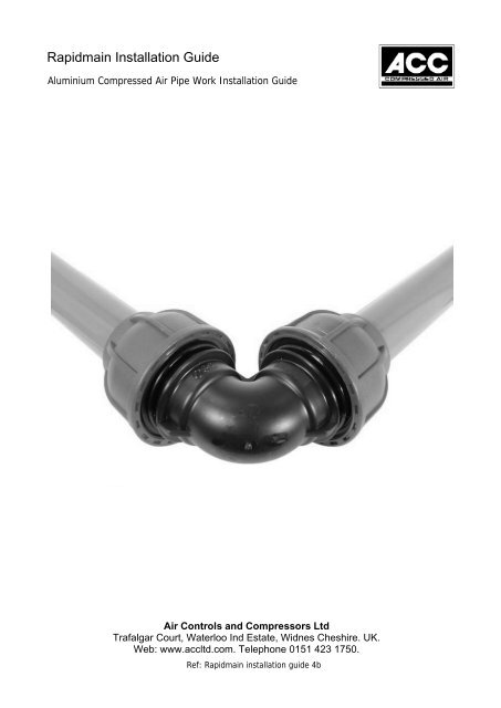
<strong>Rapidmain</strong> <strong>Installation</strong> <strong>Guide</strong><br />
Aluminium Compressed <strong>Air</strong> Pipe Work <strong>Installation</strong> <strong>Guide</strong><br />
<strong>Air</strong> Controls <strong>and</strong> Compressors Ltd<br />
Trafalgar Court, Waterloo Ind Estate, Widnes Cheshire. UK.<br />
Web: www.accltd.com. Telephone 0151 423 1750.<br />
Ref: <strong>Rapidmain</strong> installation guide 4b
Aluminium Compressed <strong>Air</strong> Pipe Work <strong>Installation</strong> <strong>Guide</strong><br />
Index<br />
1. <strong>Rapidmain</strong> fittings: Assembly <strong>and</strong> locking torque setting ……………………….…… 3 - 5<br />
2. Calculating compressed air flow ……………………….………………………………..…… 6<br />
4. Design layout for thermal expansion …………………………………….…………………. 7<br />
5. Pipe work fall <strong>and</strong> further points to consider …………………………………..……….. 8 - 9<br />
6. Pipe work bracket support. Bracket types <strong>and</strong> their use ……………..……………. 10<br />
7. Take-offs lines (branch lines) <strong>and</strong> the use of flexible pipe …………………………. 11<br />
Brief Specification<br />
Working Pressure - 0.6 to 13 bar (- 8 to 191 PSI)<br />
Media<br />
Compressed <strong>Air</strong> <strong>and</strong> other Neutral Gas<br />
Flow Range 20 to 63 mm 0.73 to 26.8 M/min (26 to 948 cfm) *<br />
Temperature Range -20 to +70 C<br />
* Flow rate calculated over 100 metres Single run line P1@ 8bar<br />
We suggest that both the installer <strong>and</strong> the user of the <strong>Rapidmain</strong> pipe<br />
installation carefully read this manual before its use <strong>and</strong> before carrying out any<br />
installation or modification work. Please also refer to the local health <strong>and</strong><br />
safety guidelines <strong>and</strong> accident prevention rules <strong>and</strong> regulations.<br />
<strong>Air</strong> Controls <strong>and</strong> Compressors Ltd<br />
Trafalgar Court, Waterloo Ind Estate, Widnes Cheshire. WA8 OSZ. UK.<br />
Web: www.accltd.com. Telephone 0151 423 1750.<br />
Page 2
<strong>Rapidmain</strong> <strong>Installation</strong> <strong>Guide</strong><br />
Aluminium Compressed <strong>Air</strong> Pipe Work <strong>Installation</strong><br />
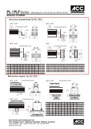
<strong>Rapidmain</strong> fittings: Assembly <strong>and</strong> locking torque settings<br />
Tightening of locking collars on fittings<br />
Assemble by h<strong>and</strong> or use our spanner set the correct torque. Black for the body <strong>and</strong> blue<br />
for the nut: See table B below<br />
Table B<br />
O D 20 25 32 40 50 63<br />
Torque 9 -11 11-13 12 - 15 15- 17 17 - 20 18 - 22<br />
L = mm 45 55 60 70 85 95<br />
Use the depth gauge on the spanner to mark<br />
the outside of the pipe: See below.<br />
Push the fitting up to the mark on the<br />
pipe <strong>and</strong> then rotate the blue locknut<br />
to secure.<br />
<strong>Air</strong> Controls <strong>and</strong> Compressors Ltd<br />
Trafalgar Court, Waterloo Ind Estate, Widnes Cheshire. WA8 OSZ. UK.<br />
Web: www.accltd.com. Telephone 0151 423 1750.<br />
Page 3
<strong>Rapidmain</strong> <strong>Installation</strong> <strong>Guide</strong><br />
Aluminium Compressed <strong>Air</strong> Pipe Work <strong>Installation</strong> <strong>Guide</strong><br />
<strong>Rapidmain</strong> fittings: Assembly <strong>and</strong> locking torque settings<br />
Chamfer Pipe<br />
If you choose to use a vice to clamp the Aluminium pipe when cutting or chamfering leave<br />
clear at least 50mm of pipe to avoid damaging the radius diameter <strong>and</strong> pipe sealing surface.<br />
On larger pipe if required use a neutral lubricant or soap.<br />
<strong>Air</strong> Controls <strong>and</strong> Compressors Ltd<br />
Trafalgar Court, Waterloo Ind Estate, Widnes Cheshire. WA8 OSZ .UK.<br />
Web: www.accltd.com. Telephone 0151 423 1750.<br />
Page 4
____________________________________________________________________________<br />
<strong>Rapidmain</strong> fittings: Assembly <strong>and</strong> locking torque settings<br />
WARNING: to avoid O-Ring damage, the tube end must be chamfered before inserting<br />
the tube into the fittings.<br />
R-Range of Compressed <strong>Air</strong> distribution fittings Sizes DN 20 to 63 OD<br />
1.1 Before use check that all the fitting connection parts are correctly assembled. Ensure you<br />
check the orientation of the locking clip; if this is incorrectly assembled the integrity of the<br />
connection cannot be guaranteed (See Table A).<br />
1.2 Before inserting the tube into the fitting rotate the light-blue coupling ring until a slight<br />
mechanical stop is felt <strong>and</strong> no further.<br />
1.3 The tube must be inserted into the fitting until the tube bottoms. This can be checked by<br />
previously marking on the tube the length “L” indicated in Table B.<br />
1.4 Once the tube has been correctly inserted into the fitting, rotate the coupling ring<br />
completely over the first mechanical stop described in Section 1.2 above until fully tight.<br />
For best results it is advisable to use the “C” type spanners shown in the catalogue.<br />
1.5 Table B shows the torque (N/m) required for each fitting size to provide the optimum<br />
mechanical operation <strong>and</strong> seal.<br />
1.6 Table C illustrates the correct alignment for installation. Misalignment of more than 5 o<br />
from the horizontal could compromise the integrity of the fitting seal.<br />
1.7 Please refer to the specifications shown in the present catalogue for pipe <strong>and</strong> fittings<br />
compatibility with chemical substances that could be present in the compressed air.<br />
1.8 <strong>Rapidmain</strong> will not be held responsible for any damage caused by improper use of their<br />
products <strong>and</strong>/or non-compliance of the manufacturers assembly instructions here within.<br />
Table A<br />
How to calculate an air system pipe size<br />
2.1 Pressure drop through fittings<br />
Although fittings are smooth inside <strong>and</strong> have the same tube internal diameter, they<br />
nonetheless cause a resistance to air flow, particularly when tubes change direction as in<br />
the case of elbows, tees, couplings <strong>and</strong> reduction fittings. Table E refers to pressure<br />
drops caused by fittings. Every fitting or change of direction has an equivalent pipe<br />
length of tube indicated in this table.<br />
2.2 <strong>Air</strong> System pipe sizing Once the compressed air consumption (l/min) <strong>and</strong> the allowable<br />
pressure drop have<br />
been calculated, refer to Table D to select the correct tube dimension. After having<br />
examined the plant <strong>and</strong> considered the changes of direction as well as the pressure drop<br />
of fittings you can then refer to Table E to complete <strong>and</strong> correct previous calculations.<br />
<strong>Air</strong> Controls <strong>and</strong> Compressors Ltd<br />
Trafalgar Court, Waterloo Ind Estate, Widnes Cheshire. WA8 OSZ. UK.<br />
Web: www.accltd.com. Telephone 0151 423 1750.<br />
Page 5
Aluminium Compressed <strong>Air</strong> Pipe Work <strong>Installation</strong> <strong>Guide</strong><br />
Calculating Compressed air flow<br />
Table C<br />
Table D<br />
Pressure drop for<br />
100 m (in bars)<br />
Effective<br />
Absolute<br />
Pressure<br />
(in bars)<br />
Delivery SRA *<br />
(in l/min)<br />
Outside<br />
diameter of<br />
the tube<br />
(mm)<br />
Referential<br />
axis<br />
Delivery SRA *<br />
Actual delivery at the effective pressure (P) x absolute pressure (P+1) in bars<br />
Temperature Correction:<br />
0 degrees + 273 <strong>Air</strong><br />
delivery at 0 degrees C = delivery 15 degrees C x ________________<br />
* SRA: St<strong>and</strong>ard Reference Atmosphere<br />
288<br />
Using the Nomogram<br />
The tube diameter can be determined by first finding the flow rate in l/m <strong>and</strong> the allowable<br />
pressure drop.<br />
a. We have chosen the working pressure on the “C” axis. A straight red line has then<br />
been drawn connecting the working pressure to the pressure drop value on the “A” axis.<br />
b. Drawing this straight line allows us to locate a point on the “R” referential axis.<br />
c. A green line has then been drawn from the referential “R” axis to the value on the<br />
“A” axis which indicates plant delivery in l/min.<br />
d. This green line intersects on the “B” axis which shows the suitable tube diameter.<br />
<strong>Air</strong> Controls <strong>and</strong> Compressors Ltd<br />
Trafalgar Court, Waterloo Ind Estate, Widnes Cheshire. WA8 OSZ .UK.<br />
Web: www.accltd.com. Telephone 0151 423 1750.<br />
Page 6
Aluminium Compressed <strong>Air</strong> Pipe Work <strong>Installation</strong> <strong>Guide</strong><br />
Design layout for thermal expansion<br />
DL = DT x 0,02 x L<br />
A = DL x 23<br />
B = 0.7 x A<br />
Variation due to<br />
thermal expansion<br />
Introduction<br />
The theoretical calculations <strong>and</strong> design criteria in this<br />
manual are only relevant where the installation<br />
ambient temperature is between 15 o C <strong>and</strong> 25 o C.<br />
Attention! Where the installation is outside of the<br />
recommended ambient temperatures indicated above,<br />
it may be necessary to take corrective action such as<br />
thermal insulation of the pipe or the inclusion of<br />
expansion/contraction loops.<br />
Calculating expansion loop dimensions<br />
On long straight runs of pipe it may be necessary to<br />
insert expansion loops in the line to prevent damage<br />
to the pipe, due to thermal movement (expansion or<br />
contraction) of the pipe.<br />
Example<br />
L1 = 40 mt L2 = 40 mt DT = 50 o C<br />
DL = DT x 0.02 x L = 50 x 0.02 x 40 = 40<br />
mm A = DL x 23 = 40 x 23 = 920 mm<br />
B = 0.7 x A = 0.7 x 920 = 640 mm<br />
Legend<br />
A-B = Quote (mm)<br />
L-L1-L2 = Lengths (mt)<br />
DL = Expansions (mm)<br />
DT = Thermal range ( o C)<br />
M = Mobile bracket<br />
F = Fix bracket<br />
Examples of Expansion Loops<br />
Vertical layout (Upwards)<br />
Horizontal<br />
Vertical layout (Downwards)<br />
“Fixed brackets” hold the pipe firmly while “sliding brackets” allow axial movement.<br />
<strong>Air</strong> Controls <strong>and</strong> Compressors Ltd<br />
Trafalgar Court, Waterloo Ind Estate, Widnes Cheshire. WA8 OSZ. UK.<br />
Web: www.accltd.com. Telephone 0151 423 1750.<br />
Page 7
Aluminium Compressed <strong>Air</strong> Pipe Work <strong>Installation</strong> <strong>Guide</strong><br />
Pipe work fall <strong>and</strong> further points to consider<br />
Fall of pipes<br />
Where possible horizontal runs should be designed to have a slight fall of (1-2%) in the direction<br />
of air flow to encourage drainage <strong>and</strong> collection of condensate at lower levels or at drop legs<br />
built within the air system, from which the condensate can be drained as required.<br />
Direction of air flow<br />
Install drains at low points where ever possible.<br />
Example<br />
Pipe Fall<br />
<strong>Air</strong> Controls <strong>and</strong> Compressors Ltd<br />
Trafalgar Court, Waterloo Ind Estate, Widnes Cheshire. WA8 OSZ.<br />
UK. Web: www.accltd.com. Telephone 0151 423 1750.<br />
Page 8
Aluminium Compressed <strong>Air</strong> Pipe Work <strong>Installation</strong> <strong>Guide</strong><br />
Pipe work fall <strong>and</strong> further points to consider<br />
To allow for system maintenance, install an adequate quantity of isolation valves in the pipe work.<br />
Valve<br />
Ball Valve<br />
Fixing of Pipes<br />
To allow for thermal movement of the pipe <strong>and</strong> to avoid stress points, the pipe should be installed<br />
<strong>and</strong> fixed to a secure surface of building, such as a wall, brickwork, roof support (direct or with<br />
hanging brackets) or the building framework using suitable “fixed <strong>and</strong> sliding brackets ” as required.<br />
Fixed<br />
bracket<br />
Fixed bracket<br />
Sliding bracket<br />
Fixed<br />
bracket<br />
<strong>Air</strong> Controls <strong>and</strong> Compressors Ltd<br />
Trafalgar Court, Waterloo Ind Estate, Widnes Cheshire. WA8 OSZ. UK.<br />
Web: www.accltd.com. Telephone 0151 423 1750.<br />
Page 9
<strong>Rapidmain</strong> <strong>Installation</strong> <strong>Guide</strong><br />
Aluminium Compressed <strong>Air</strong> Pipe Work <strong>Installation</strong> <strong>Guide</strong><br />
Pipe work bracket support. Bracket types <strong>and</strong> there use<br />
Bracket <strong>and</strong> Pipe support centres<br />
It is important to install the pipe work brackets with correct spacing. Always try to<br />
support the pipe joint with a bracket located within 200 to 500 mm from the pipe joint.<br />
Please refer to the diagram below for examples of preferred installation<br />
Install brackets by each joint to support<br />
the pipe joint<br />
Suggested Maximum Support Centres)<br />
DN 20/25 32 40 50 63<br />
P (MT) 2.5 3 3.5 4 4.5<br />
Legend<br />
L = Length (mt)<br />
P = Brackets support centre (mt)<br />
M = Bracket<br />
G = Joint<br />
An alternative to the “st<strong>and</strong>ard” aluminium expansion loop,<br />
is to use suitable flexible hose assembly as shown below.<br />
DL = DT x 0,2 x L<br />
B = (2 x R) + DL 1 + DL 2<br />
Legend<br />
L1-L2 = Lengths (mt)<br />
DL1-DL2 = Expansion (mm)<br />
DT = Thermal range ( o C)<br />
M = Bracket<br />
R = Radius (mm)<br />
A-B = Quotes (mm)<br />
Quote R – A (mm)<br />
DN 20 25 32 40 50 63<br />
R (mm) 70 85 100 130 160 200<br />
A (mm) 370 390 500 560 600 800<br />
Attention!<br />
Tables are valid only for stainless steel flexible hoses<br />
type 1REX/INOX/N/321/DN.<br />
For other types refer to the manufacturer’s<br />
technical documentation<br />
<strong>Air</strong> Controls <strong>and</strong> Compressors Ltd<br />
Trafalgar Court, Waterloo Ind Estate, Widnes Cheshire. WA8 OSZ. UK.<br />
Web: www.accltd.com. Telephone 0151 423 1750.<br />
Page10
Aluminium Compressed <strong>Air</strong> Pipe Work <strong>Installation</strong> <strong>Guide</strong><br />
Take-off lines (branch lines) <strong>and</strong> the use of flexible pipe<br />
DL = DT x 0,2 x L<br />
A = DL x Y<br />
Legend<br />
A = Quote (mm)<br />
L1-L2 = Lengths (mt)<br />
DL = Expansion (mm)<br />
DT = Thermal range ( o C)<br />
F = Fixed bracket<br />
U = Use<br />
Y = Calculation factor<br />
Calculation Factor Y<br />
DN 20 25 32 40 50 63<br />
Y 20 20 25 28 33 40<br />
Bends using flexible hose.<br />
Using a flexible hose in corners is also<br />
acceptable. They can be used for the change of<br />
direction <strong>and</strong> at the same time to compensate<br />
for any thermal movement.<br />
L min = 1000 mm<br />
At the end of a pipe run always<br />
terminate the pipe <strong>and</strong> the fitting to<br />
an fixed anchored point eg: Wall<br />
Legend<br />
L1-L2 = Lengths (mt)<br />
DL1-DL2 = Expansion (mm)<br />
M = Bracket<br />
R = Radius (mm)<br />
L = Length of flexible pipe (mm)<br />
Pd 20od=0.2 b(3 psi) 6m/sec<br />
Pd 63od=2.5%(3 psi) 12m/sec<br />
Avoid installing flexible hoses with to tight a radius or where the<br />
hose is subject to, too much stretch<br />
<strong>Air</strong> Controls <strong>and</strong> Compressors Ltd<br />
Trafalgar Court, Waterloo Ind Estate, Widnes Cheshire. WA8 OSZ. UK.<br />
Web: www.accltd.com. Telephone 0151 423 1750.<br />
Page 11