LITHIUM ION BATTERY CHARGER USING C8051F300 Relevant ...
LITHIUM ION BATTERY CHARGER USING C8051F300 Relevant ...
LITHIUM ION BATTERY CHARGER USING C8051F300 Relevant ...

You also want an ePaper? Increase the reach of your titles
YUMPU automatically turns print PDFs into web optimized ePapers that Google loves.
AN137<br />
<strong>LITHIUM</strong> <strong>ION</strong> <strong>BATTERY</strong> <strong>CHARGER</strong> <strong>USING</strong> <strong>C8051F300</strong><br />
<strong>Relevant</strong> Devices<br />
This application note applies to the following devices:<br />
<strong>C8051F300</strong><br />
Introduction<br />
Driven by the need for untethered mobility and<br />
ease of use, many systems rely on rechargable batteries<br />
as their primary power source. The battery<br />
charging circuitry for these systems is typically<br />
implemented using a fixed-function IC to control<br />
the charging current/voltage profile.<br />
The C8051F30x family provides a flexible alternative<br />
to fixed-function battery chargers. This application<br />
note discusses how to use the C8051F30x<br />
family in Li-Ion battery charger applications. The<br />
Li-Ion charging algorithms can be easily adapted to<br />
other battery chemistries, but an understanding of<br />
other battery chemistries is required to ensure<br />
proper charging for those chemistries.<br />
Key Points<br />
• On-chip high-speed, 8-bit ADC provides superior<br />
accuracy in monitoring charge voltage<br />
(critical to prevent overcharging in Li-Ion<br />
applications), maximizing charge effectiveness<br />
and battery life.<br />
• On-chip PWM provides means to implement<br />
buck converter with a very small external<br />
inductor.<br />
• On-chip Temp sensor provides an accurate and<br />
stable drive voltage for determining battery<br />
temperature. An external RTD (resistive temperature<br />
device) can also be used via the flexible<br />
analog input AMUX.<br />
• A single C8051F30x platform provides full<br />
product range for multi-chemistry chargers,<br />
expediting time to market and reducing inventory.<br />
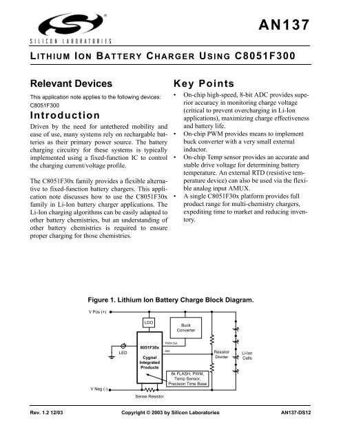
Figure 1. Lithium Ion Battery Charge Block Diagram.<br />
V Pos (+)<br />
V Neg (-)<br />
LED<br />
LDO<br />
8051F30x<br />
Cygnal<br />
Integrated<br />
Products<br />
Sense Resistor<br />
PWM Out<br />
AIN<br />
Buck<br />
Converter<br />
8k FLASH, PWM,<br />
Temp Sensor,<br />
Precision Time Base<br />
Resistor<br />
Divider<br />
Rev. 1.2 12/03 Copyright © 2003 by Silicon Laboratories AN137-DS12<br />
Li-Ion<br />
Cells
AN137<br />
Charging Basics<br />
Batteries are exhaustively characterized to determine<br />
safe yet time-efficient charging profiles. The<br />
optimum charging method for a battery is dependent<br />
on the battery’s chemistry (Li-Ion, NiMH,<br />
NiCd, SLA, etc.). However, most charging strategies<br />
implement a 3-phase scheme:<br />
1. Low-current conditioning phase<br />
2. Constant-current phase<br />
3. Constant-voltage phase/charge termination<br />
All batteries are charged by transferring electrical<br />
energy into them (refer to the references at the end<br />
of this note for a battery primer). The maximum<br />
charge current for a battery is dependent on the battery’s<br />
rated capacity (C). For example, a battery<br />
with a cell capacity of 1000mAh is referred to as<br />
being charged at 1C (1 times the battery capacity) if<br />
the charge current is 1000mA. A battery can be<br />
charged at 1/50C (20 mA) or lower if desired.<br />
However, this is a common trickle-charge rate and<br />
is not practical in fast charge schemes where short<br />
charge-time is desired.<br />
Most modern chargers utilize both trickle-charge<br />
and rated charge (also referred to as bulk charge)<br />
while charging a battery. The trickle-charge current<br />
is usually used in the initial phases of charging to<br />
minimize early self heating which can lead to premature<br />
charge termination. The bulk charge is usually<br />
used in the middle phase where the most of the<br />
battery’s energy is restored.<br />
During the final phase of battery charge, which<br />
generally takes the majority of the charge time,<br />
either the current or voltage or a combination of<br />
both are monitored to determine when charging is<br />
complete. Again, the termination scheme depends<br />
on the battery’s chemistry. For instance, most Lithium<br />
Ion battery chargers hold the battery voltage<br />
constant, and monitor for minimum current. NiCd<br />
2 Rev. 1.2<br />
batteries use a rate of change in voltage or temperature<br />
to determine when to terminate.<br />
Note that while charging a battery, most of the electrical<br />
energy is stored in a chemical process, but not<br />
all as no system is 100 percent efficient. Some of<br />
the electrical energy is converter to thermal energy,<br />
heating up the battery. This is fine until the battery<br />
reaches full charge at which time all the electrical<br />
energy is converted to thermal energy. In this case,<br />
if charging isn’t terminated, the battery can be<br />
damaged or destroyed. Fast chargers (chargers that<br />
charge batteries fully in less than a couple hours)<br />
compound this issue, as these chargers use a high<br />
charge current to minimize charge time. As one can<br />
see, monitoring a battery’s temperature is critical<br />
(especially for Li-Ion as they explode if overcharged).<br />
Therefore, the temperature is monitored<br />
during all phases. Charge is terminated immediately<br />
if the temperature rises out of range.<br />
Li-Ion Battery Charger -<br />
Hardware<br />
Currently, Li-Ion batteries are the battery chemistry<br />
of choice for most applications due to their high<br />
energy/space and energy/weight characteristics<br />
when compared to other chemistries. Most modern<br />
Li-Ion chargers use the tapered charge termination,<br />
minimum current (see Figure 2), method to ensure<br />
the battery is fully charged as does the example<br />
code provided at the end of this note.<br />
Buck Converter<br />
The most economical way to create a tapered termination<br />
charger is to use a buck converter. A buck<br />
converter is a switching regulator that uses an<br />
inductor and/or a transformer (if isolation is<br />
desired), as an energy storage element to transfer<br />
energy from the input to the output in discrete<br />
packets (for our example we use an inductor; the<br />
capacitor in Figure 3 is used for ripple reduction).<br />
Feedback circuitry regulates the energy transfer via<br />
the transistor, also referred to as the pass switch, to<br />
maintain a constant voltage or constant current
Conditioning<br />
Phase<br />
within the load limits of the circuit. See Figure 3<br />
for details.<br />
Tapered Charger Using the F30x<br />
Figure 3 illustrates an example buck converter<br />
using the ‘F30x. The pass switch is controlled via<br />
the on-chip 8-bit PWM (Pulse Width Modulator)<br />
output of the PCA. When the switch is on, current<br />
will flow like in Figure 3A. The capacitor is<br />
charged from the input through the inductor. The<br />
inductor is also charged. When the switch is<br />
opened (Figure 3B), the inductor will try to maintain<br />
its current flow by inducing a voltage as the<br />
current through an inductor can’t change instantaneously.<br />
The current then flows through the diode<br />
and the inductor charges the capacitor. Then the<br />
cycle repeats itself. On a larger scale, if the duty<br />
cycle is decreased (shorter “on” time), the average<br />
Power<br />
Source<br />
Figure 2. Lithium Ion Charge Profile.<br />
Charge Current<br />
Charge Voltage<br />
Current regulation Voltage regulation<br />
(A) (B)<br />
Pass Switch On<br />
Shottky<br />
Diode<br />
Capacitor<br />
Inductor<br />
Figure 3. Buck Converter.<br />
Battery<br />
Time<br />
AN137<br />
voltage decreases and vice versa. Therefore, controlling<br />
the duty cycles allows one to regulate the<br />
voltage or the current to within desired limits.<br />
Selecting the Buck Converter Inductor<br />
To size the inductor in the buck converter, one first<br />
assumes a 50 percent duty cycle, as this is where<br />
the converter operates most efficiently.<br />
Duty cycle is given by Equation 1, where T is the<br />
period of the PWM (in our example T = 10.5µS).<br />
Power<br />
Source<br />
Pass Switch Off<br />
Shottky<br />
Diode<br />
DutyCycle =<br />
Capacitor<br />
Inductor<br />
ton<br />
--------<br />
T<br />
Equation 1. Duty Cycle.<br />
Battery<br />
Rev. 1.2 3
AN137<br />
With this established, select a PWM switching frequency.<br />
As Equation 2<br />
shows, the larger the PWM switching frequency,<br />
the smaller (and more cost effective) the inductor.<br />
Our example code configures the ‘F30x’s 8-bit<br />
hardware PWM to use the internal master clock of<br />
24.5MHz divided by 256 to generate a 95.7kHz<br />
switch rate.<br />
Now we can calculate the inductor’s size. Assuming<br />
V i , the charging voltage, is 15V, V sat , the saturation<br />
voltage, is 0.5V, the desired output voltage,<br />
V o, is 4.2V, and I 0MAX , the maximum output current,<br />
is 1500 mA, the inductor should be at least<br />
18µH.<br />
Note that the capacitor in this circuit is simply a<br />
ripple reducer. The larger it is the better as ripple is<br />
inversely proportional to the size of the cap. For<br />
more details on buck converters, refer to the references<br />
listed at the end of this note.<br />
Li-Ion Battery Charger -<br />
Software<br />
The software example that follows demonstrates a<br />
Li-Ion battery charger using the <strong>C8051F300</strong>. The<br />
F300 is designed for high-level languages like “C”<br />
and includes an 8-bit 8051 based micro-controller,<br />
an 8-bit 500 ksps ADC, 8k FLASH, an 8-bit and<br />
16-bit PWM, and a 2% accurate oscillator all onchip.<br />
The algorithms discussed are written entirely<br />
in “C” making them easily portable. Refer to the<br />
F300’s datasheet for a full description of the<br />
device.<br />
Calibration<br />
L =<br />
(<br />
---------------------------------------------------<br />
Vi – Vsat – Vo)ton<br />
2Iomax<br />
Equation 2. Inductor Size.<br />
4 Rev. 1.2<br />
To ensure accurate voltage and current measurements,<br />
the algorithms use a two-point system calibration<br />
scheme. In this scheme, the user is expected<br />
to apply two known voltages and two known currents,<br />
preferable, one point near ground and the<br />
other point near full-scale. The algorithm then<br />
takes these two points, calculates a slope and an<br />
offset for both the current and voltage channels,<br />
and stores the results in FLASH. All future conversions<br />
are scaled relative to these slope and offset<br />
calculations. Note that if an external amplifier is<br />
used for the current channel, it will need to be calibrated<br />
with a similar two-point calibration scheme<br />
to ensure maximum accuracy.<br />
Temperature<br />
To monitor the temperature, the algorithms use the<br />
on-chip temperature sensor. The sensor is left<br />
uncalibrated, but still provides a sufficiently accurate<br />
temperature measurement. For more accurate<br />
temperature measurement, one or two-point temperature<br />
calibration is required.<br />
An external temperature sensor can be used if<br />
desired. The AMUX can to be reconfigured to<br />
accommodate this additional input voltage.<br />
Current<br />
The charge-current to the battery cells is monitored<br />
by taking a differential voltage reading across a<br />
small but accurate sense resistor. The current is<br />
amplified through the on-chip PGA, digitized by<br />
the on-chip 8-bit ADC, and scaled accordingly via<br />
the slope and offset calibration coefficients. An<br />
external gain stage may be necessary if more resolution<br />
is desired for the current measurement.<br />
Voltage<br />
The battery’s voltages are divided down and monitored<br />
via external resistors. Note that this example<br />
uses the supply voltage as the ADC voltage reference.<br />
Any monitored voltage above the reference<br />
voltage must be divided down for accurate moni-
toring. If a more accurate reference is required, an<br />
external voltage reference can be used. Adjustment<br />
to the divide resistors must be made accordingly.<br />
Charging - Phase1<br />
In phase 1, (for description purposes, we assume<br />
the battery is initially discharged), the ‘F30x regulates<br />
the battery’s current to I LOWCURRENT (typically<br />
1/50 C) until the battery’s voltage reaches<br />
V MINVOLTBULK . Note that the battery’s charge current<br />
is current limited to I LOWCURRENT to ensure<br />
safe initial charge and to minimize battery selfheating.<br />
If at any time the temperature increases out<br />
of limit, charging is halted.<br />
Charging - Phase 2<br />
Once the battery reaches V MINVOLTBULK the<br />
charger enters phase 2, where the battery’s algorithm<br />
controls the PWM pass switch to ensure the<br />
output voltage provides a constant charge-current<br />
I BULK to the battery (rate or bulk current is usually<br />
1C and is definable in the header file as is<br />
I LOWCURRENT and V MINVOLTBULK ).<br />
Charging - Phase 3<br />
After the battery reaches V Top (typically 4.2 V in<br />
single cell charger), the charger algorithm enters<br />
phase 3, where the PWM feeds back and regulates<br />
the battery’s voltage. In phase 3, the battery continues<br />
to charge until the battery’s charge current<br />
reaches I MINIBULKl , after which, the battery is<br />
charged for an additional 30 minutes and then<br />
charge terminates. Phase 3 typically takes the<br />
majority of the charging time.<br />
Note that in most practical applications, such as a<br />
portable PC, the batteries may be in any of the three<br />
phases when charging is activated. This doesn’t<br />
really affect the charger as it simply monitor’s the<br />
AN137<br />
battery’s current condition and starts charging from<br />
that point.<br />
Conclusion<br />
The <strong>C8051F300</strong>’s high level of analog integration,<br />
small form-factor, integrated FLASH memory, and<br />
low power consumption makes it ideal for flexible<br />
next generation battery charging applications. This<br />
application note discussed how to use the<br />
C8051F30x family in Lithium Ion battery charger<br />
applications. Example code is provided as well.<br />
References<br />
Maxim Integrated Product, “DC-DC Converter<br />
Tutorial”.<br />
Martinez, Carlos and Drori, Yossi and Ciancio,<br />
Joe, “AN126 Smart Battery Primer”, Xicor, October<br />
1999.<br />
Rev. 1.2 5
AN137<br />
Appendix<br />
Figure 4. 1 Cell Battery Charger Schematic.<br />
6 Rev. 1.2
Figure 5. 1 Cell Buck Converter Schematic.<br />
AN137<br />
Rev. 1.2 7
AN137<br />
Error<br />
Detected<br />
?<br />
Turn off LED0, Error<br />
Infinite Loop<br />
Yes/No<br />
Figure 6. main() Flow Chart.<br />
main()<br />
Config_F300()<br />
BULK_charge()<br />
8 Rev. 1.2<br />
No<br />
CalibrateADCfor<br />
Measurement()<br />
Enable Interrupts<br />
Clear Termination Flags<br />
Clear Charge Status Flags<br />
Yes<br />
No<br />
Infinite<br />
Loop<br />
SW0<br />
Pressed?<br />
?<br />
Yes<br />
Yes/No<br />
Error<br />
Detected<br />
?<br />
No<br />
Status = BULK<br />
?<br />
Yes<br />
Turn on LED0<br />
Status =<br />
LOWCURRENT<br />
?<br />
Yes<br />
No<br />
LOWCURRENT_charge()
Figure 7. CalibrateADCforMeasurement() Flow Chart.<br />
CalibrateADCforMearurement()<br />
SW0<br />
Pushed<br />
?<br />
No<br />
Yes<br />
Setup ADC0's AMUX,<br />
Throughput, Gain, for near<br />
zero-scale voltage cal point<br />
Acquire 16-bit<br />
Measurement<br />
Setup ADC0's AMUX,<br />
Throughput, Gain, for near<br />
full-scale voltage cal point<br />
Acquire16-bit<br />
Measurement<br />
Calculate Voltage Slope<br />
Coefficient<br />
Calculate Voltage Offset<br />
Coefficient<br />
Erase Memory Page<br />
0x1A00<br />
Store Voltage Offset and<br />
Slope Coefficients in<br />
FLASH Memory<br />
SW0<br />
Pushed<br />
?<br />
Yes<br />
Setup ADC0's AMUX,<br />
Throughput, Gain, for near<br />
zero-scale Current cal point<br />
Acquire 16-bit<br />
Measurement<br />
Setup ADC0's AMUX,<br />
Throughput, Gain, for near<br />
full-scale Current cal point<br />
Acquire16-bit<br />
Measurement<br />
Calculate Current Slope<br />
Coefficient<br />
Calculate Current Offset<br />
Coefficient<br />
Store Current Offset and<br />
Slope Coefficients in<br />
FLASH Memory<br />
END<br />
No<br />
AN137<br />
Rev. 1.2 9
AN137<br />
AMUX = Current AMUX = Volt<br />
No<br />
Monitor_Battery()<br />
Measurement<br />
Type<br />
?<br />
Current Charge Voltage Temperature Battery Voltage<br />
Yes<br />
AV = 0<br />
I = 0<br />
I≤10?<br />
Start ADC0<br />
ADC0 Done?<br />
Yes<br />
AV = AV + ADC0 Turn PWM on<br />
AV = AV/10<br />
Figure 8. Monitor_Battery() Flow Chart.<br />
10 Rev. 1.2<br />
No<br />
Voltage w/ or w/out PWM<br />
Calculate Voltage w/<br />
Calibration Coefficients<br />
Stop PWM<br />
AMUX = Temperature<br />
Current<br />
Calculate Current w/<br />
Calibration Coefficients<br />
Return Desired Parameter<br />
END<br />
Stop PWM<br />
AMUX = Volt<br />
Temperature<br />
Calculate Temperature w/<br />
Calibration Coefficients
Figure 9. Bulk_Charge() Flow Chart (Part 1).<br />
Set Appropriate Flags<br />
No<br />
No<br />
No<br />
No<br />
Bulk_Charge()<br />
Start PWM w/ Zero Output<br />
Yes<br />
Change Status from<br />
const_C to const_V<br />
Status = const_C<br />
T<br />
Within Limits<br />
?<br />
V<br />
min_Bulk<br />
?<br />
Calculate bulk_finish_time<br />
Green LED On<br />
Status =<br />
BULK & No<br />
Error?<br />
Yes<br />
Status =<br />
const_c<br />
?<br />
Yes<br />
Regulate Battery Current<br />
Read Charge Voltage<br />
Charge<br />
Voltage Within<br />
Limits<br />
?<br />
B C<br />
A<br />
D<br />
Yes<br />
Yes<br />
No<br />
AN137<br />
Rev. 1.2 11
AN137<br />
Figure 10. BULKCurrent() Flow Chart (Part 2).<br />
B C<br />
A<br />
D<br />
Stop PWM<br />
& Flag Error<br />
Stop PWM<br />
& Flag Error<br />
Status =<br />
const_V<br />
?<br />
Regulate Voltage()<br />
Time<br />
Overflow<br />
?<br />
Temp.<br />
Overflow<br />
?<br />
60 Sec.<br />
Over<br />
?<br />
Status = const_C<br />
Status = LOWCURRENT<br />
Green LED Off<br />
12 Rev. 1.2<br />
No<br />
No<br />
Yes<br />
Yes<br />
No<br />
Yes<br />
No<br />
const_V,<br />
NOT Delay & Current<br />
Below Threshold<br />
?<br />
Calculate bulk_finish_time<br />
Status = Delay<br />
Delay<br />
Time<br />
Over<br />
?<br />
Yes<br />
Stop PWM<br />
END<br />
No<br />
Yes<br />
Yes<br />
No
Status = Delay<br />
Green LED Off<br />
END<br />
Figure 11. LowCurrent_Charge() Flow Chart.<br />
No<br />
LOWCURRENT_charge()<br />
No<br />
No<br />
ResetTimeBase()<br />
Calculate Finish_time<br />
No ERROR &<br />
LOWCURRENT =1<br />
?<br />
Temp<br />
within Limits<br />
?<br />
V<br />
AN137<br />
Figure 12. Turn_PWM_Off() Flow Chart.<br />
No<br />
Turn_PWM_Off()<br />
CEX0<br />
Counter<br />
Figure 13. Measure() Flow Chart.<br />
measure()<br />
Set accumulator and<br />
counter i variables to zero<br />
Clear End of Conversion<br />
Flag<br />
Start New Conversion<br />
Conversion<br />
Complete<br />
?<br />
i = 0<br />
?<br />
END<br />
Yes<br />
accumulator =<br />
accumulator + ADC0<br />
Increment i<br />
Yes<br />
Return 16-bit<br />
Measurement<br />
No<br />
No<br />
AN137<br />
Rev. 1.2 15
AN137<br />
Regulate_Voltage()<br />
Measure Battery's<br />
voltage<br />
Voltage <<br />
VOLT_BULK &<br />
PCA not max<br />
?<br />
Make Duty Cycle Larger<br />
Voltage<br />
< VOLT_BULK + Tolerence<br />
& > VOLT_BULK<br />
?<br />
END<br />
Figure 14. Regulate_Voltage() Flow Chart.<br />
Yes<br />
Yes<br />
16 Rev. 1.2<br />
No<br />
No<br />
No<br />
Voltage ><br />
VOLT_BULK &<br />
PCA not 0<br />
Yes<br />
Make Duty Cycle Smaller
Figure 15. Regulate_Current() Flow Chart.<br />
Regulate_Current()<br />
Measure Current<br />
Current <<br />
passed current &<br />
PCA not max<br />
?<br />
Make Duty Cycle Larger<br />
END<br />
Yes<br />
Current =<br />
passed value<br />
?<br />
Yes<br />
Monitor Voltage<br />
w/ PWM off<br />
Voltage <<br />
VOLT_LOWCURRENT<br />
± Tolerence<br />
?<br />
Yes<br />
CHARGE_STATUS =<br />
const_V<br />
No<br />
No<br />
No<br />
No<br />
Current ><br />
passed current &<br />
PCA not 0<br />
Yes<br />
Make Duty Cycle Smaller<br />
AN137<br />
Rev. 1.2 17
AN137<br />
No<br />
No<br />
Figure 16. PCA_OVERFLOW_ISR() Flow Chart.<br />
Turn Off LED<br />
LOW<br />
CURRENT<br />
charge &<br />
no errors<br />
?<br />
18 Rev. 1.2<br />
Yes<br />
odd<br />
second<br />
?<br />
Yes<br />
Turn on LED<br />
PCA_OVERFLOW_ISR()<br />
No<br />
No<br />
No<br />
Reset PCA Counter and<br />
PCA Interrupts<br />
Decrement time.count<br />
0 = time.count<br />
Yes<br />
Reset time.count to<br />
overflow value<br />
Increment time.sec<br />
60 = time.sec<br />
?<br />
Yes<br />
Reset time.sec<br />
Increment time.min<br />
60 = time.min<br />
?<br />
Yes<br />
Increment time.hour<br />
Reset time.min<br />
24 = time.hour<br />
Yes<br />
Reset time.hour<br />
No<br />
END
-----------------------------------------------------------------------------<br />
//<br />
// Copyright 2002 Cygnal Integrated Products, Inc.<br />
//<br />
// Filename: LI<strong>ION</strong>_BC_MAIN.h<br />
// Target Device: 8051F300<br />
// Created: 11 SEP 2002<br />
// Created By: DKC<br />
// Tool chain: KEIL Eval C51<br />
//<br />
// This header file is used to define all preprocessor directives, prototypes,<br />
// and global variable for LI<strong>ION</strong>_BC_MAIN.c.<br />
//<br />
// The user should modify this header file before proceeding as key<br />
// battery parameter limits are set here.<br />
//<br />
//-----------------------------------------------------------------------------<br />
// Function Prototypes<br />
//----------------------------------------------------------------------------void<br />
Config_F300(void);<br />
void Reset_Time_Base(void);<br />
void CalibrateADCforMeasurement(void);<br />
void Regulate_Current(int);<br />
void Regulate_Voltage(void);<br />
void Turn_PWM_Off(void);<br />
int Monitor_Battery(unsigned char);<br />
void Bulk_Charge(void);<br />
void Lowcurrent_Charge(void);<br />
unsigned int Measure(void);<br />
void Delay_Loop(void);<br />
//-----------------------------------------------------------------------------<br />
// UN<strong>ION</strong>s, STRUCTUREs, and ENUMs<br />
//----------------------------------------------------------------------------typedef<br />
union LONG { // byte-addressable LONG<br />
long l;<br />
unsigned char b[4];<br />
} LONG;<br />
typedef union INT { // byte-addressable INT<br />
int i;<br />
unsigned char b[2];<br />
} INT;<br />
typedef struct<br />
{<br />
unsigned long int t_count;<br />
int sec; // global seconds<br />
int min; // global minutes<br />
int hour; // global hour<br />
}time_struct;<br />
//-----------------------------------------------------------------------------<br />
// Global Variable Definitions<br />
AN137<br />
Rev. 1.2 19
AN137<br />
//----------------------------------------------------------------------------time_struct<br />
TIME; // Global Struct to Track Time<br />
char bdata TERMINAT<strong>ION</strong>; // Global Variable to Track Termination<br />
char bdata CHARGE_STATUS; // Global Variable to Track Charging<br />
INT code CHECK_BYTE _at_ 0x1A00; // 0x0A0A Default value, for later use<br />
LONG code VOLT_SLOPE _at_ 0x1A60; // Volt Slope Register<br />
LONG code VOLT_OFFSET _at_ 0x1A64; // Volt Offset Register<br />
LONG code I_NOAMP_SLOPE _at_ 0x1A70; // Current Slope Register,ext. amp off<br />
LONG code I_NOAMP_OFFSET _at_ 0x1A74; // Current Offset Register,ext. amp.off<br />
LONG temp_LONG_1,temp_LONG_2; // Temporary Storage Variables<br />
INT temp_INT_1,temp_INT_2; // Temporary Storage Variables<br />
//-----------------------------------------------------------------------------<br />
// Bit maskable CHARGE STATUS Register Definition<br />
//----------------------------------------------------------------------------sbit<br />
BULK = CHARGE_STATUS^0; // bit 0 : BULK charge status bit<br />
sbit LOWCURRENT = CHARGE_STATUS^1; // bit 1 : LOWCURRENT charge status bit<br />
sbit ERROR = CHARGE_STATUS^2; // bit 2 : ERROR before/during charging<br />
sbit CONST_V = CHARGE_STATUS^3; // bit 3 : charged w/ constant VOLTAGE<br />
sbit CONST_C = CHARGE_STATUS^4; // bit 4 : charged w/ constant CURRENT<br />
sbit DELAY = CHARGE_STATUS^5; // bit 5 : BULK charge DELAY for LiIon<br />
// after CURRENT threshold detection<br />
sbit READY = CHARGE_STATUS^6; // bit 6 : Lowcurrent charge is<br />
// terminated; battery is charged<br />
sbit FREE1 = CHARGE_STATUS^7; // bit 7 : Not Currently used<br />
//-----------------------------------------------------------------------------<br />
// Bit Maskable TERMINAT<strong>ION</strong> Register Definition<br />
//----------------------------------------------------------------------------sbit<br />
TEMP_MIN = TERMINAT<strong>ION</strong>^0; // bit 0 : minimum TEMPERATURE overflow<br />
sbit TEMP_MAX = TERMINAT<strong>ION</strong>^1; // bit 1 : maximum TEMPERATURE overflow<br />
sbit I_MIN = TERMINAT<strong>ION</strong>^2; // bit 2 : minimum CURRENT overflow<br />
sbit I_MAX = TERMINAT<strong>ION</strong>^3; // bit 3 : maximum CURRENT overflow<br />
sbit TIME_MAX = TERMINAT<strong>ION</strong>^4; // bit 4 : maximum time overflow<br />
sbit VOLT_MAX = TERMINAT<strong>ION</strong>^5; // bit 5 : maximum VOLTAGE overflow<br />
sbit VOLT_MIN = TERMINAT<strong>ION</strong>^6; // bit 6 : minimum VOLTAGE overflow<br />
sbit FREE2 = TERMINAT<strong>ION</strong>^7; // bit 7 : Not Currently used<br />
//-----------------------------------------------------------------------------<br />
// Bit maskable PORT Definitions<br />
//----------------------------------------------------------------------------sbit<br />
SDA = P0 ^ 0; // bit 0 : SDA In/Output, Pin P0.<br />
sbit SCL = P0 ^ 1; // bit 1 : SCL Output, Pin P1.<br />
sbit CEX0 = P0 ^ 2; // bit 2 : PWM Output, Pin P2.<br />
sbit LED0 = P0 ^ 3; // bit 3 : LED0, Pin P0.3<br />
sbit SW0 = P0 ^ 7; // bit 7 : Switch0, Pin P0.7<br />
// AMUX Selections; Analog Inputs<br />
#define TBAT 0xF8; // bit 4 : Temp. Ch.; Analog In<br />
#define IBAT 0x65; // bit 5 : Current Ch.; Analog In<br />
#define VBAT 0xF6; // bit 6 : Voltage Ch.; Analog In<br />
//-----------------------------------------------------------------------------<br />
// 8051F300 PARAMETERS<br />
//-----------------------------------------------------------------------------<br />
#define SYSCLK 24500000 // System clock frequency<br />
20 Rev. 1.2
#define TEMP_SENSOR_GAIN 3300 // Temp Sensor Gain in (uV / degC)<br />
#define TEMP_GAIN 2 // PGA gain setting<br />
#define CURRENT_GAIN 4 // PGA gain setting<br />
#define VREF 3200 // ADC Voltage Reference (mV)<br />
#define SCRATCH_PAGE 0x1C00 // FLASH page used for temp storage<br />
#define PWM_CLOCK SYSCLK/255 // PWM frequency is 96 kHz<br />
//-----------------------------------------------------------------------------<br />
// Calibration/Calculation PARAMETERS<br />
//-----------------------------------------------------------------------------<br />
#define V1_CAL 67 // 1st cal point for 2 point cal.<br />
#define V2_CAL 2800 // 2nd cal point for 2 point cal.<br />
#define I1_CAL 67 // 1st cal point for 2 point cal.<br />
#define I2_CAL 133 // 2nd cal point for 2 point cal.<br />
#define RSENSE 1 // RSENSE is assumed to be 1/2 ohm<br />
#define RESB 20 // 10k Ohms, Voltage Divide Resistor<br />
#define RESAB 30 // 20k Ohms, Voltage Divide Resistor<br />
#define TEMP_SLOPE ((long) TEMP_GAIN * TEMP_SENSOR_GAIN * 65536 / 100 / VREF)<br />
// An estimate of the Temperature<br />
// in [tenth codes / K]<br />
// The temperature measurement is<br />
// within 3 degrees of accuracy.<br />
//-----------------------------------------------------------------------------<br />
// Monitor_Battyer Switch PARAMETERS<br />
//-----------------------------------------------------------------------------<br />
#define TEMPERATURE 7 // Value for Switch Statement<br />
#define VOLTAGE 5 // Value for Switch Statement<br />
#define VOLTAGE_PWM_OFF 3 // Value for Switch Statement<br />
#define CURRENT 1 // Value for Switch Statement<br />
//-----------------------------------------------------------------------------<br />
// Battery/Pack Parameters<br />
//-----------------------------------------------------------------------------<br />
#define CELLS 1 // Number of cells in the battery pack<br />
#define CAPACITY 150 // mAh, Battery Capacity (LiIon)<br />
#define LiIon_CELL_VOLT 4200 // mV, Nominal Charge Voltage<br />
#define I_BULK (unsigned int)(CAPACITY)<br />
#define I_LOWCURRENT (unsigned int)(CAPACITY/4)<br />
#define VOLT_BULK (unsigned int)(LiIon_CELL_VOLT)<br />
#define VOLT_LOWCURRENT (unsigned int)(LiIon_CELL_VOLT)<br />
#define VOLT_TOLERANCE (unsigned int)(LiIon_CELL_VOLT/100)// 1 Percent Acc<br />
#define CURRENT_TOLERENCE (unsigned int)(CAPACITY/10) // 10 Percent Acc<br />
//-----------------------------------------------------------------------------<br />
// Battery Characteristics: Charge TERMINAT<strong>ION</strong> Limits<br />
//-----------------------------------------------------------------------------<br />
#define MIN_TEMP_ABS 26300 // Abs. min. TEMPERATURE = -10 C, 263K<br />
#define MAX_TEMP_ABS 32300 // Abs. max. TEMPERATURE = 50C, 323K:<br />
AN137<br />
Rev. 1.2 21
AN137<br />
#define MIN_VOLT_BULK 3000 // Minimum BULK Voltage<br />
#define MAX_VOLT_ABS (unsigned int)(CELLS * LiIon_CELL_VOLT)<br />
#define MIN_I_BULK (unsigned int)(CAPACITY/4)<br />
#define MAX_TIME_LOWCURRENT 30 // Max Lowcurrent Charge Time = 90min<br />
#define MAX_TIME_BULK 90 // Maximum BULK Charge Time = 90 min<br />
// at 1C CURRENT<br />
#define BULK_TIME_DELAY 30 // DELAY = 30min after “MIN_I_BULK”<br />
// END OF FILE<br />
22 Rev. 1.2
-----------------------------------------------------------------------------<br />
//<br />
// Copyright 2002 Cygnal Integrated Products, Inc.<br />
//<br />
// Filename: LI<strong>ION</strong>_BC_MAIN.c<br />
// Target Device: 8051F300<br />
// Created: 11 SEP 2002<br />
// Created By: DKC<br />
// Tool chain: KEIL Eval C51<br />
//<br />
// This is a stand alone battery charger for a Lithium <strong>ION</strong> battery.<br />
// It utilizes a buck converter, controlled by the on-chip 8-bit PWM,<br />
// to provide constant current followed by constant voltage battery charge.<br />
//<br />
//-----------------------------------------------------------------------------<br />
// Includes<br />
//-----------------------------------------------------------------------------<br />
#include <br />
#include “LI<strong>ION</strong>_BC_MAIN.h” // Battery Hearder File<br />
//-----------------------------------------------------------------------------<br />
// Functions<br />
//-----------------------------------------------------------------------------<br />
void Config_F300(void)<br />
{ RSTSRC = 0x02; // Enable VDD Monitor<br />
XBR0 = 0x70; // Skip P0.4,5,6; they’re analog In<br />
XBR1 = 0x44; // Enable SMBus on P0.0, P0.1, and CEX0<br />
XBR2 = 0x40; // as PWM at P0.2<br />
// Enable crossbar and weak pull-ups<br />
P0MDOUT = 0x0C; // Set P0.2 & P0.3 output to push-pull<br />
P0MDIN = 0x8F; // Configure P0.4,5,6 as Analog Inputs<br />
OSCICN = 0x07; // Set SYSCLK to 24.5MHz, internal osc.<br />
ADC0CN = 0xC0; // Turn on the ADC Module;<br />
// enable low power mode for settling<br />
REF0CN = 0x0C; // Configure ADC’s to use VDD for<br />
// Voltage Reference,<br />
// Enable On-chip Temperature Sensor<br />
//-----------------------------------------------------------------------------<br />
// PCA Configuration<br />
//-----------------------------------------------------------------------------<br />
PCA0MD = 0x00; // Disable WDT<br />
PCA0MD = 0x08; // Set PWM Time base = SYSCLK<br />
PCA0L = 0x00; // Initialize PCA Counter to Zero<br />
PCA0H = 0x00;<br />
PCA0CN = 0x40; // Enable PCA Counter<br />
// Clear PCA Counter Overflow flag<br />
//Module 0<br />
PCA0CPM0 = 0x00; // Configure CCM0 to 8-bit PWM mode<br />
PCA0CPL0 = 0xF0; // Initialize PCA PWM to small duty cycle<br />
PCA0CPH0 = 0xF0; // 0xF0 Ensures a Soft Initial Charge<br />
AN137<br />
Rev. 1.2 23
AN137<br />
}<br />
//Module 1<br />
PCA0CPM1 = 0x49; // Configure Module 1 as software timer<br />
PCA0CPL1 = 0xFF; // Initialize to 255 so that Interrupt<br />
// is generated when PCA ends<br />
// 8-bit PWM Cycle<br />
PCA0CPH1 = 0x00; // PCA0CPH is the high byte of the<br />
// Output Compare Module<br />
EIE1 = 0x08; // Enable PCA Overflow Interrupt<br />
//-----------------------------------------------------------------------------<br />
// Reset_Time_Base - Resets all Time Counting Values<br />
//----------------------------------------------------------------------------void<br />
Reset_Time_Base()<br />
{<br />
TIME.sec = 0x00;<br />
TIME.min = 0x00;<br />
TIME.hour = 0x00;<br />
TIME.t_count = PWM_CLOCK;<br />
}<br />
//-----------------------------------------------------------------------------<br />
// Delay - This is a Delay to permit time for Switches to Debounce<br />
//----------------------------------------------------------------------------void<br />
Delay_Loop (void)<br />
{<br />
long i=0;<br />
for (i=0;i
Once ready, Get the 2nd calibration voltage<br />
AMX0SL = VBAT; // Change Mux for second point<br />
temp_INT_2.i = Measure();<br />
// Calculate the SLOPE // V1 and V2 are in tenth of a degree<br />
temp_LONG_1.l = (unsigned)(temp_INT_2.i-temp_INT_1.i);<br />
temp_LONG_1.l *= (unsigned)100; // Account for Math Truncation Error<br />
temp_LONG_1.l /= (unsigned)(V2_CAL - V1_CAL);<br />
// Calculate the OFFSET<br />
temp_LONG_2.l = (unsigned)temp_INT_1.i;<br />
temp_LONG_2.l -= (signed)(temp_LONG_1.l * V1_CAL/100);<br />
temp_LONG_1.l = 2050; // If no cal. use these<br />
temp_LONG_2.l = 0; // as default values<br />
// Erased memory at page 0x1A00<br />
pwrite = (char xdata *)&(CHECK_BYTE.b[0]);<br />
PSCTL = 0x03; // MOVX writes target FLASH memory;<br />
// FLASH erase operations enabled<br />
FLKEY = 0xA5; // FLASH key sequence #1<br />
FLKEY = 0xF1; // FLASH key sequence #2<br />
*pwrite = 0x00; // initiate PAGE erase<br />
// Write the Volt SLOPE and OFFSET to Flash<br />
PSCTL = 1; // MOVX writes to Flash<br />
pwrite = (char xdata *)&(VOLT_SLOPE.b[0]);<br />
FLKEY = 0xA5;<br />
FLKEY = 0xF1; // enable flash write<br />
*pwrite = temp_LONG_1.b[0];<br />
pwrite = (char xdata *)&(VOLT_SLOPE.b[1]);<br />
FLKEY = 0xA5;<br />
FLKEY = 0xF1; // enable flash write<br />
*pwrite = temp_LONG_1.b[1];<br />
pwrite = (char xdata *)&(VOLT_SLOPE.b[2]);<br />
FLKEY = 0xA5;<br />
FLKEY = 0xF1; // enable flash write<br />
*pwrite = temp_LONG_1.b[2];<br />
pwrite = (char xdata *)&(VOLT_SLOPE.b[3]);<br />
FLKEY = 0xA5;<br />
FLKEY = 0xF1; // enable flash write<br />
*pwrite = temp_LONG_1.b[3];<br />
pwrite = (char xdata *)&(VOLT_OFFSET.b[0]);<br />
FLKEY = 0xA5;<br />
FLKEY = 0xF1; // enable flash write<br />
*pwrite = temp_LONG_2.b[0];<br />
pwrite = (char xdata *)&(VOLT_OFFSET.b[1]);<br />
FLKEY = 0xA5;<br />
FLKEY = 0xF1; // enable flash write<br />
*pwrite = temp_LONG_2.b[1];<br />
pwrite = (char xdata *)&(VOLT_OFFSET.b[2]);<br />
FLKEY = 0xA5;<br />
FLKEY = 0xF1; // enable flash write<br />
*pwrite = temp_LONG_2.b[2];<br />
AN137<br />
Rev. 1.2 25
AN137<br />
pwrite = (char xdata *)&(VOLT_OFFSET.b[3]);<br />
FLKEY = 0xA5;<br />
FLKEY = 0xF1; // enable flash write<br />
*pwrite = temp_LONG_2.b[3];<br />
PSCTL = 0; // MOVX writes target XRAM<br />
//-----------------------------------------------------------------------------<br />
// Initialize CalibrateADCforCurrentMeasurement_NOAMP<br />
//-----------------------------------------------------------------------------<br />
// This function calibrates the current channel with no external amp<br />
// and stores the calibration coefficients in the<br />
// parameters i_noamp_slope and i_noamp__offset.<br />
//<br />
// This calibration routine uses a 2 point cal.<br />
// Wait until calibration voltage is ready for cal<br />
while (SW0 == 1); // Wait until SW0 pushed<br />
Delay_Loop(); // Wait for Switch Bounce<br />
// Once ready, Get the first calibration voltage<br />
AMX0SL = IBAT; // Select appropriate input for AMUX<br />
ADC0CF = (SYSCLK/5000000)
}<br />
FLKEY = 0xA5;<br />
FLKEY = 0xF1; // enable flash write<br />
*pwrite = temp_LONG_1.b[2];<br />
pwrite = (char xdata *)&(I_NOAMP_SLOPE.b[3]);<br />
FLKEY = 0xA5;<br />
FLKEY = 0xF1; // enable flash write<br />
*pwrite = temp_LONG_1.b[3];<br />
pwrite = (char xdata *)&(I_NOAMP_OFFSET.b[0]);<br />
FLKEY = 0xA5;<br />
FLKEY = 0xF1; // enable flash write<br />
*pwrite = temp_LONG_2.b[0];<br />
pwrite = (char xdata *)&(I_NOAMP_OFFSET.b[1]);<br />
FLKEY = 0xA5;<br />
FLKEY = 0xF1; // enable flash write<br />
*pwrite = temp_LONG_2.b[1];<br />
pwrite = (char xdata *)&(I_NOAMP_OFFSET.b[2]);<br />
FLKEY = 0xA5;<br />
FLKEY = 0xF1; // enable flash write<br />
*pwrite = temp_LONG_2.b[2];<br />
pwrite = (char xdata *)&(I_NOAMP_OFFSET.b[3]);<br />
FLKEY = 0xA5;<br />
FLKEY = 0xF1; // enable flash write<br />
*pwrite = temp_LONG_2.b[3];<br />
PSCTL = 0; // MOVX writes target XRAM<br />
//-----------------------------------------------------------------------------<br />
// Measure<br />
//-----------------------------------------------------------------------------<br />
//<br />
// This routine averages 65536 ADC samples and returns a 16-bit unsigned<br />
// result.<br />
//<br />
unsigned int Measure (void)<br />
{<br />
unsigned i; // sample counter<br />
unsigned long accumulator=0L; // here’s where we integrate the<br />
// ADC samples<br />
}<br />
// read the ADC value and add to running total<br />
i = 0;<br />
do {<br />
AD0INT = 0; // clear end-of-conversion indicator<br />
AD0BUSY = 1; // initiate conversion<br />
while(!AD0INT); // wait for conversion to complete<br />
accumulator += ADC0; // read adc value and accumulate<br />
i++; // update counter<br />
} while (i != 0x0000);<br />
// the accumulator now contains 16 added bits of which 8 are usable<br />
return (unsigned int) (accumulator >> 8);<br />
//-----------------------------------------------------------------------------<br />
// Regulate_Current<br />
//-----------------------------------------------------------------------------<br />
// This routine monitors the battery’s current and adjusts<br />
// the PWM (i.e. duty cycle) to keep the current at a known value<br />
AN137<br />
Rev. 1.2 27
AN137<br />
//<br />
void Regulate_Current(int passed_current)<br />
{ unsigned int temp = 0;<br />
}<br />
do{<br />
temp = Monitor_Battery(CURRENT); // Measure Current<br />
if (temp < passed_current)<br />
PCA0CPH0--;<br />
if (temp > passed_current)<br />
PCA0CPH0++;<br />
}while ((temp < (passed_current - CURRENT_TOLERENCE)) ||<br />
(temp > (passed_current + CURRENT_TOLERENCE)));<br />
// I_BULK or I_LOWCURRENT is set now<br />
temp = Monitor_Battery(VOLTAGE_PWM_OFF);<br />
// If VOLTAGE within range,<br />
// change from constant CURRENT charge<br />
// mode to constant VOLTAGE charge mode<br />
if ((temp >= (VOLT_LOWCURRENT - VOLT_TOLERANCE)) &&<br />
(temp VOLT_BULK)<br />
PCA0CPH0++;<br />
}while ((temp < (VOLT_BULK - VOLT_TOLERANCE)) ||<br />
(temp > (VOLT_BULK + VOLT_TOLERANCE)));<br />
// VOLTAGE is set now<br />
//-----------------------------------------------------------------------------<br />
// Turn_PWM_Off<br />
//-----------------------------------------------------------------------------<br />
// This routine peforms a soft charge turn off by taking the PWM’s<br />
// duty cycle slowly to zero.<br />
//<br />
void Turn_PWM_Off(void)<br />
{<br />
28 Rev. 1.2
}<br />
do{<br />
if (PCA0CPH0 < 0xF0)<br />
PCA0CPH0++;<br />
}while (PCA0CPH0 < 0xF0);<br />
// Duty Cycle is now small and safe to turn off.<br />
PCA0CPM0 = 0x00; // Disable PWM<br />
//-----------------------------------------------------------------------------<br />
// Monitor_Battery<br />
//-----------------------------------------------------------------------------<br />
// This routine acts as a switch when gathering different conversion types.<br />
// It adjusts the throughput, adjust the AMUX and returns the current in mA,<br />
// voltage in mV, and temperature in C, 2% accurate.<br />
//<br />
int Monitor_Battery(unsigned char value)<br />
{<br />
char i;<br />
unsigned long av =0;<br />
long signed result;<br />
ADC0CF = (SYSCLK/5000000)
AN137<br />
}<br />
av = av/10; // Compute the average<br />
av = av
CONST_C = 1; // Start in constant current charge mode<br />
DELAY = 0; // Reset timer DELAY<br />
temp = Monitor_Battery(TEMPERATURE); // Monitor Temperature<br />
// Is temperature within range?<br />
if ((temp > MIN_TEMP_ABS) && (temp < MAX_TEMP_ABS))<br />
{<br />
temp = Monitor_Battery(VOLTAGE); // Monitor Voltage<br />
// Is Voltage within range?<br />
if ((temp MIN_VOLT_BULK)<br />
{<br />
PCA0CPM0 = 0x42; // Configure CCM0 to 8-bit PWM mode<br />
// Enter main loop in Bulk_Charge()<br />
while ((BULK == 1) && (ERROR == 0))<br />
{<br />
if (CONST_C == 1)<br />
Regulate_Current(I_BULK); // Charge with Constant Current<br />
{<br />
else if (CONST_V == 1)<br />
Regulate_Voltage(); // Charge with Constant Voltage<br />
// Now, Check for error and charge termination conditions<br />
// If above max charge time, flag error<br />
// Test for BULK Charge Time Out<br />
// Monitor Time<br />
if ((TIME.hour == bulk_finish_hour) && (TIME.min == bulk_finish_min)<br />
&& (DELAY == 0))<br />
{<br />
Turn_PWM_Off(); // Turn Off PWM<br />
TIME_MAX = 1; // Set Time max error flag<br />
ERROR = 1; // Set general error flag<br />
}<br />
// Monitor Temperature<br />
temp = Monitor_Battery(TEMPERATURE);<br />
if ((temp < MIN_TEMP_ABS) && (temp > MAX_TEMP_ABS))<br />
Turn_PWM_Off(); // Turn Off PWM<br />
if (temp < MIN_TEMP_ABS)<br />
TEMP_MIN = 1; // Set Temperature below minimum flag<br />
else<br />
TEMP_MAX = 1; // Set Temperature exceeds maximum flag<br />
}<br />
ERROR = 1; // Set general error flag<br />
// Minute elapsed?<br />
// Check for minimum current<br />
// if reached, enter last DELAY charge<br />
if (TIME.min != last_min)<br />
{<br />
last_min = TIME.min;<br />
if ((CONST_V == 1) && (DELAY == 0) && (Monitor_Battery(CURRENT)<br />
AN137<br />
}<br />
}<br />
}<br />
{<br />
}<br />
// Calculate TOP OFF Battery Time finish time<br />
delay_min = (TIME.min + BULK_TIME_DELAY);<br />
delay_hour = TIME.hour;<br />
while (delay_min > 60)<br />
{<br />
delay_min = delay_min - 60;<br />
delay_hour++;<br />
}<br />
DELAY = 1; // Set Delay Flag<br />
// Monitor Delay time, time up?<br />
if ((TIME.hour == delay_hour)&&(TIME.min == delay_min) &&<br />
(DELAY == 1))<br />
{<br />
Turn_PWM_Off(); // Turn Off PWM<br />
CONST_V = 0; // Exit CONST_V<br />
CONST_C = 1; // Prepare to enter CONST_C<br />
BULK = 0; // Prepare to exit BULK mode<br />
LOWCURRENT = 1; // Prepare to enter LOWCURRENT Mode<br />
}<br />
}<br />
} // End Main While loop<br />
else if(ERROR == 0)<br />
{<br />
if (temp > (MAX_VOLT_ABS + VOLT_TOLERANCE))<br />
{ VOLT_MAX = 1; // Set Max Voltage error flag<br />
ERROR = 1; // Set general error flag<br />
}<br />
else if(temp < MIN_VOLT_BULK)<br />
{ VOLT_MIN = 1; // Set Minimum bulk voltage error flag<br />
LOWCURRENT = 1; // Switch to LOWCURRENT mode<br />
BULK = 0; // Exit Bulk Charge mode<br />
} // battery’s voltage very low<br />
}<br />
else if(ERROR == 0) // Absolute temperature out of range?<br />
{<br />
if (temp < MIN_TEMP_ABS)<br />
TEMP_MIN = 1; // Set Temperature below minimum flag<br />
else<br />
TEMP_MAX = 1; // Set Temperature exceeds maximum flag<br />
}<br />
ERROR = 1; // Set general error flag<br />
//-----------------------------------------------------------------------------<br />
// Lowcurrent_Charge<br />
//-----------------------------------------------------------------------------<br />
void Lowcurrent_Charge(void)<br />
{<br />
unsigned int temp = 0;<br />
unsigned int lowcurrent_finish_min = 0;<br />
32 Rev. 1.2
unsigned int lowcurrent_finish_hour = 0;<br />
Reset_Time_Base(); // Reset Time base to zero<br />
// Calculate LOWCURRENT finish time<br />
lowcurrent_finish_min = (TIME.min + MAX_TIME_LOWCURRENT);<br />
lowcurrent_finish_hour = TIME.hour;<br />
while (lowcurrent_finish_min > 60)<br />
{<br />
lowcurrent_finish_min = lowcurrent_finish_min - 60;<br />
lowcurrent_finish_hour++;<br />
}<br />
// Enter Main Lowcurrent Loop.<br />
// Only exits are upon error and full charge<br />
while ((LOWCURRENT == 1) && (ERROR == 0))<br />
{<br />
temp = Monitor_Battery(TEMPERATURE);// Get Temperature Reading<br />
// Is TEMPERATURE within limits<br />
if ((temp > MIN_TEMP_ABS) && (temp < MAX_TEMP_ABS))<br />
{<br />
// Is Battery’s Charge Voltage below max charge voltage<br />
temp = Monitor_Battery(VOLTAGE); // Get Voltage Reading<br />
if (temp = MIN_VOLT_BULK) && (DELAY == 0))// Bulk Threshold voltage met?<br />
{ LOWCURRENT = 0; // Exit LOWCURRENT mode<br />
BULK = 1; // Switch to Bulk Charge mode<br />
}<br />
// Check elapsed time<br />
if ((TIME.hour == lowcurrent_finish_hour) &&<br />
( TIME.min == lowcurrent_finish_min))<br />
{<br />
TIME_MAX = 1; // Set Time MAX error flag<br />
ERROR = 1; // Set general error flag<br />
}<br />
}<br />
else if(ERROR == 0) // Voltage to high?<br />
{<br />
VOLT_MAX = 1; // Set Max voltage error flag<br />
ERROR = 1; // Set general error flag<br />
}<br />
}<br />
else if(ERROR == 0) // Absolute temperature out of range?<br />
{<br />
if (temp < MIN_TEMP_ABS)<br />
TEMP_MIN = 1; // Set Temperature below minimum flag<br />
else<br />
TEMP_MAX = 1; // Set Temperature exceeds maximum flag<br />
ERROR = 1; // Set general error flag<br />
AN137<br />
Rev. 1.2 33
AN137<br />
}<br />
//-----------------------------------------------------------------------------<br />
// Main Function<br />
//----------------------------------------------------------------------------void<br />
main(void)<br />
{<br />
EA = 0; // Disable All Interrupts<br />
Reset_Time_Base();<br />
Config_F300(); // Config F300<br />
CalibrateADCforMeasurement(); // Calibrate F300<br />
}<br />
EA = 1; // Enable All Active Interrupts<br />
while(1)<br />
{<br />
LED0 = 0; // Turn LED0 off<br />
}<br />
TERMINAT<strong>ION</strong> = 0x00; // Reset Termination Flags<br />
CHARGE_STATUS = 0x00; // Reset Charge Status Flags<br />
BULK = 1; // Start in LOWCURRENT Charge mode<br />
CONST_C = 1;<br />
while (SW0 == 1); // Wait until SW0 pushed<br />
Delay_Loop(); // Wait for Switch Bounce<br />
while (ERROR == 0)<br />
{<br />
if (BULK == 1)<br />
{<br />
LED0 = 1; // Turn LED0,indicates Bulk Mode<br />
Bulk_Charge(); // Enter Bulk Charge Mode<br />
}<br />
if (LOWCURRENT == 1)<br />
Lowcurrent_Charge(); // Enter Lowcurrent_Charge function<br />
// Toggle LED0 at 1 Hz rate via ISR<br />
}<br />
if (ERROR == 1)<br />
{<br />
Turn_PWM_Off();; // Turn PWM Off<br />
LED0 = 0; // Turn OFF LED0 to indicate “ERROR”.<br />
EA = 0; // Disable All Interrupts<br />
while (1); // Enter a eternal loop<br />
// No recovery except “reset-button”<br />
}<br />
//-----------------------------------------------------------------------------<br />
// PCA_ISR<br />
//-----------------------------------------------------------------------------<br />
// This routine counts the elapsed time in seconds, minutes, hours.<br />
// It also toggles LED0 every second when in Lowcurrent Charge Mode.<br />
// This routine interrupts every time the PCA counter overflows, every 256<br />
// SYSCLK cycles. After SYSCLK/256 interrupts, one second has elapsed.<br />
//<br />
void PCA_OVERFLOW_ISR (void) interrupt 9<br />
{<br />
34 Rev. 1.2
}<br />
PCA0CN = 0x40; // Reset all PCA Interrupt Flags<br />
PCA0H = 0x00; // Reset High Byte of PCA Counter<br />
// of 8-bit PWM we are using Module1<br />
if (0x0000 == --TIME.t_count)<br />
{<br />
TIME.t_count = PWM_CLOCK; // Reset 1 Second Clock<br />
if ( 60 == ++TIME.sec ) // Account for elapsed seconds<br />
{ // Reset second counter every minute<br />
TIME.sec = 0x00;<br />
if ( 60 == ++TIME.min ) // Account for elapsed minutes<br />
{ // Reset minute counter every hour<br />
TIME.min = 0x00;<br />
if ( 24 == ++TIME.hour ) // Account for elapsed hours<br />
TIME.hour = 0x00; // Reset hour counter every day<br />
}<br />
}<br />
}<br />
if ((LOWCURRENT == 1) && (ERROR == 0))<br />
{ // Blink LED0 at 1 Hz if in Lowcurrent<br />
if (TIME.sec % 2)<br />
LED0 = 0; // Turn on LED every odd second<br />
else<br />
LED0 = 1; // Turn on LED every even second<br />
}<br />
// END OF FILE<br />
AN137<br />
Rev. 1.2 35
AN137<br />
Contact Information<br />
Silicon Laboratories Inc.<br />
4635 Boston Lane<br />
Austin, TX 78735<br />
Tel: 1+(512) 416-8500<br />
Fax: 1+(512) 416-9669<br />
Toll Free: 1+(877) 444-3032<br />
Email: productinfo@silabs.com<br />
Internet: www.silabs.com<br />
The information in this document is believed to be accurate in all respects at the time of publication but is subject to change without notice.<br />
Silicon Laboratories assumes no responsibility for errors and omissions, and disclaims responsibility for any consequences resulting from<br />
the use of information included herein. Additionally, Silicon Laboratories assumes no responsibility for the functioning of undescribed features<br />
or parameters. Silicon Laboratories reserves the right to make changes without further notice. Silicon Laboratories makes no warranty, representation<br />
or guarantee regarding the suitability of its products for any particular purpose, nor does Silicon Laboratories assume any liability<br />
arising out of the application or use of any product or circuit, and specifically disclaims any and all liability, including without limitation consequential<br />
or incidental damages. Silicon Laboratories products are not designed, intended, or authorized for use in applications intended to<br />
support or sustain life, or for any other application in which the failure of the Silicon Laboratories product could create a situation where personal<br />
injury or death may occur. Should Buyer purchase or use Silicon Laboratories products for any such unintended or unauthorized application,<br />
Buyer shall indemnify and hold Silicon Laboratories harmless against all claims and damages.<br />
Silicon Laboratories and Silicon Labs are trademarks of Silicon Laboratories Inc.<br />
Other products or brandnames mentioned herein are trademarks or registered trademarks of their respective holders.<br />
36 Rev. 1.2