csf_mini.pdf - Harmonic Drive LLC
csf_mini.pdf - Harmonic Drive LLC
csf_mini.pdf - Harmonic Drive LLC

Create successful ePaper yourself
Turn your PDF publications into a flip-book with our unique Google optimized e-Paper software.
M i n i a t u r e<br />
PRINCIPLE AND STRUCTURE<br />
G e a r h e a d s<br />
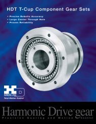
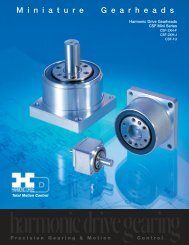
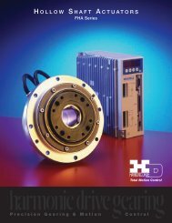
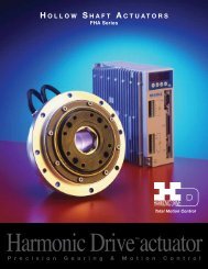
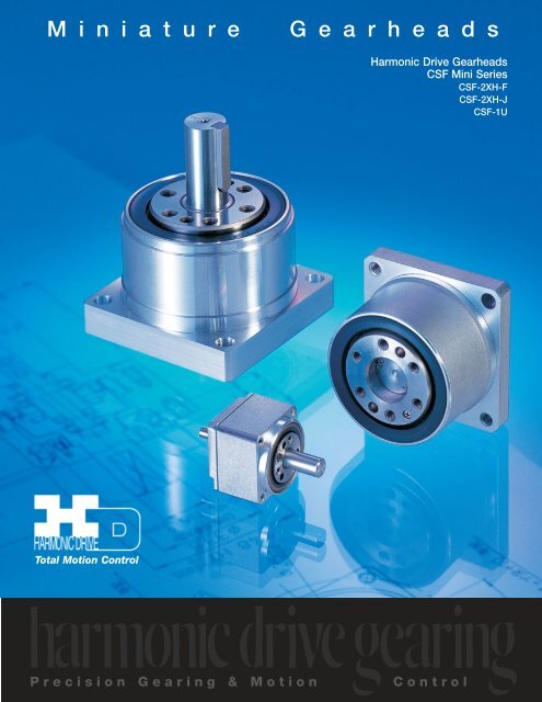
<strong>Harmonic</strong> <strong>Drive</strong> Gearheads<br />
CSF Mini Series<br />
CSF-2XH-F<br />
CSF-2XH-J<br />
CSF-1U<br />
Total Motion Control<br />
Precision Gearing & Motion<br />
<strong>Harmonic</strong> <strong>Drive</strong> <strong>LLC</strong> 800-921-3332<br />
Control
CSF MINI SERIES<br />
<strong>Harmonic</strong> drive gearing Is the next generation<br />
in precision motion control.<br />
<strong>Harmonic</strong> <strong>Drive</strong> Precision Control Speed Reducers for compact models<br />
are available in this CSF Mini Series.<br />
Future<br />
Zero-Backlash, High Positional Accuracy, High Repeatability<br />
The innovative design of harmonic drive gearing allows consistently<br />
high performance over the life of the gear.<br />
Compact, Lightweight, High Torque Capacity<br />
<strong>Harmonic</strong> <strong>Drive</strong> <strong>LLC</strong>’ patented “S” gear tooth profile achieves twice the torque,<br />
life and torsional stiffness as compared to gears of the same size by<br />
allowing up to 30% of the gear teeth to be engaged at all times.<br />
Compact 4-Point Contact Ball Bearing Mounted In Main Shaft<br />
A high performance 4-point contact output bearing supports the output<br />
flange/shaft. This bearing has excellent run-out characteristics and can<br />
support high radial, axial and moment loads.<br />
Wide Range Of Gear Ratios And Input/Output Configurations<br />
In Each Size<br />
Gear Ratios 30:1, 50:1, and 100:1 are available in each size. This allows<br />
servomotor and gearhead combinations to operate over a wide speed range.<br />
In addition, each size has 3 input/output shaft/flange configurations allowing<br />
convenient methods for attaching loads, motors, and pulleys.<br />
2
CONTENTS<br />
About <strong>Harmonic</strong> drive gearing<br />
Principle and Structure. . . . . . . . . . . . . . . . . . . . . . . . . . . . . . . . . . . 04<br />
Driving Configuration . . . . . . . . . . . . . . . . . . . . . . . . . . . . . . . . . . . . 05<br />
Application Example. . . . . . . . . . . . . . . . . . . . . . . . . . . . . . . . . . . . . 06<br />
Ordering Information Model and Code . . . . . . . . . . . . . . . . . . . . . . . 06<br />
Rating Table. . . . . . . . . . . . . . . . . . . . . . . . . . . . . . . . . . . . . . . . . . . 07<br />
Definition of Ratings . . . . . . . . . . . . . . . . . . . . . . . . . . . . . . . . . . . . 07<br />
Strength and Life . . . . . . . . . . . . . . . . . . . . . . . . . . . . . . . . . . . . . . . 08<br />
Selection Procedure. . . . . . . . . . . . . . . . . . . . . . . . . . . . . . . . . . . . . 09<br />
Selection Example . . . . . . . . . . . . . . . . . . . . . . . . . . . . . . . . . . . . . . 10<br />
Unit Type CSF-<strong>mini</strong><br />
External Dimensions. . . . . . . . . . . . . . . . . . . . . . . . . . . . . . . . . . . . . 11<br />
Specification for Cross Roller Bearing. . . . . . . . . . . . . . . . . . . . . . . . 12<br />
Output Bearing Ratings . . . . . . . . . . . . . . . . . . . . . . . . . . . . . . . . . . 13<br />
Specifications of Output Bearings . . . . . . . . . . . . . . . . . . . . . . . . . . 14<br />
Engineering Data<br />
Efficiency . . . . . . . . . . . . . . . . . . . . . . . . . . . . . . . . . . . . . . . . . . . . . 15<br />
No Load Running Torque . . . . . . . . . . . . . . . . . . . . . . . . . . . . . . . . . 17<br />
Starting Torque and Backdriving Torque . . . . . . . . . . . . . . . . . . . . . . 19<br />
Positioning Accuracy . . . . . . . . . . . . . . . . . . . . . . . . . . . . . . . . . . . . 19<br />
Torsional Stiffness . . . . . . . . . . . . . . . . . . . . . . . . . . . . . . . . . . . . . . 20<br />
Recommended Tolerance for Assembly . . . . . . . . . . . . . . . . . . . . . . 22<br />
Performance Data for Input Bearing . . . . . . . . . . . . . . . . . . . . . . . . . 23<br />
Installation of Case Side. . . . . . . . . . . . . . . . . . . . . . . . . . . . . . . . . . 24<br />
Tolerances for Assembly. . . . . . . . . . . . . . . . . . . . . . . . . . . . . . . . . . 25<br />
Warranty and Safety<br />
Warranty . . . . . . . . . . . . . . . . . . . . . . . . . . . . . . . . . . . . . . . . . . . . . 25<br />
Safety Guide . . . . . . . . . . . . . . . . . . . . . . . . . . . . . . . . . . . . . . . . . . 26<br />
<strong>Harmonic</strong> <strong>Drive</strong> <strong>LLC</strong> 800-921-3332 3
PRINCIPLE AND STRUCTURE<br />
About harmonic drive gearing principle and structure<br />
0 º<br />
90º<br />
360º<br />
Circular Spline<br />
Wave Generator<br />
Flexspline<br />
The Flexspline is elliptically shaped by The<br />
Wave Generator and engaged with the<br />
Circular Spline at the major elliptical axis.<br />
The teeth completely disengage on the<br />
minor axis.<br />
When the Circular Spline is fixed and<br />
the Wave generator rotates clockwise,<br />
the Flexspline is elastically deformed<br />
and rotates counterclockwise relative to<br />
the Circular Spline.<br />
For each 360 degrees clockwise movement<br />
of the Wave Generator,the Flexspline<br />
moves counterclockwise by two teeth<br />
relative to the Circular Spline.<br />
System Components<br />
The Wave Generator: A thin raced ball bearing fitted onto an elliptical plug serving as a high efficiency torque converter.<br />
The Flexspline: A non-rigid, thin cylindrical cup with external teeth on a slightly smaller pitch diameter than the Circular Spline.<br />
It fits over and is held in an elliptical shape by the Wave Generator.<br />
The Circular Spline: A rigid ring with internal teeth, engaging the teeth of the Flexspline across the major axis of the<br />
Wave Generator.<br />
GEARHEAD TYPE (IU)<br />
This gearhead is easy to use and has both an input and<br />
output shaft. It also allows for pulleys to be used for the<br />
input and output to the gearhead.<br />
GEARHEAD TYPE (2XH)<br />
This gearhead is designed to be coupled directly to a servomotor.<br />
It is available in 2 models. 2XH-F:Direct input coupling/<br />
output Flange. 2XH-J: Direct input coupling/output Shaft.<br />
4 Point Contact Bearing<br />
Circular Spline<br />
4 Point Contact Bearing<br />
Circular Spline<br />
Output (FS)<br />
Input (WG)<br />
Rotary System<br />
Wave Generator<br />
Output Flange<br />
Wave Generator<br />
Flexspline<br />
Flexspline<br />
4
DRIVING CONFIGURATIONS<br />
Driving Configurations<br />
A variety of different driving<br />
configurations are possible, as shown<br />
below. The reduction ratio given in<br />
the tables on page 10 and 11 correspond<br />
to arrangement 1, in which the Wave<br />
Generator acts as the input element,<br />
the Circular Spline is fixed and the<br />
Flexspline acts as the output element.<br />
input speed<br />
Ratio =<br />
output speed<br />
WG<br />
CS<br />
FS<br />
1. Reduction Gearing<br />
CS Fixed<br />
WG Input<br />
FS Output<br />
Ratio = —<br />
R<br />
1<br />
[Equation 1]<br />
Input and output in opposite direction.<br />
2. Reduction Gearing<br />
FS Fixed<br />
WG Input<br />
CS Output<br />
Ratio =<br />
R + 1<br />
1<br />
[Equation 2]<br />
Input and output in same direction.<br />
3. Reduction Gearing<br />
WG Fixed<br />
FS Input<br />
CS Output<br />
Ratio =<br />
R + 1<br />
R<br />
[Equation 3]<br />
Input and output in same direction.<br />
4. Speed Increaser Gearing<br />
WG Fixed<br />
CS Input<br />
FS Output<br />
Ratio =<br />
R<br />
R + 1<br />
[Equation 4]<br />
Input and output in same direction.<br />
5. Speed Increaser Gearing<br />
CS Fixed<br />
FS Input<br />
WG Output<br />
Ratio = —<br />
1<br />
R<br />
[Equation 5]<br />
Input and output in opposite direction.<br />
6. Speed Increaser Gearing<br />
FS Fixed<br />
CS Input<br />
WG Output<br />
Ratio =<br />
1<br />
R + 1<br />
[Equation 6]<br />
Input and output in same direction.<br />
7. Differential Gearing<br />
WG Control Input<br />
CS Main <strong>Drive</strong>-Input<br />
FS Main <strong>Drive</strong>-Output<br />
Numerous differential functions can<br />
be obtained by combinations of the<br />
speed and rotational direction of<br />
the three basic elements. [Equation 7]<br />
<strong>Harmonic</strong> <strong>Drive</strong> <strong>LLC</strong><br />
800-921-3332<br />
5
APPLICATION EXAMPLE<br />
Application for 2XH<br />
Flange<br />
Reverse for<br />
Motor with long<br />
output shaft<br />
Flange<br />
Motor Matching Table<br />
Table 1<br />
Manufacturer Yaskawa / Mini-Series Mitsubishi / HC-AQ Series Matsushita minas<br />
Motor Capacity 3W-5W 10W 20W 30W 10W 20W 30W 30W<br />
CSF-5-2X •<br />
CSF-8-2XH • •<br />
CSF-11-2XH • • • • •<br />
CSF-14-2XH • • •<br />
M<br />
ORDERING INFORMATION<br />
CSG - 14 - 100 - 2XH - F - SP<br />
Name of Model Size Gear Ratio Model SP<br />
Name Size Gear Ratio Model SP<br />
5 30, 50, 100<br />
1U<br />
Customized specification<br />
CSF 8 30, 50, 100<br />
2XH-F<br />
(special)<br />
11 30, 50, 100<br />
14 30, 50, 80, 100<br />
2XH-J<br />
shape and performance<br />
6
RATING TABLE<br />
Rating Table Table 2<br />
Size Gear Ratio Rated Torque at 2000rpm Repeated peak torque Max. average load torque Max. momentary torque Max. Input Speed Avg. Input Speed Moment of Inertia(1/4 GD) 2<br />
Nm in.lb Nm in.lb Nm in.lb Nm in.lb r/min r/min 1U 2XH<br />
30 0.25 2 0.5 4 0.38 3 0.9 8<br />
5 50 0.4 4 0.9 8 0.53 5 1.8 16 10,000 6,500 2.5x10 -4 2.5x10 -4<br />
100 0.6 5 1.4 12 0.94 8 2.7 24<br />
30 0.9 8 1.8 16 1.4 12 3.3 29<br />
8 50 1.8 16 3.3 29 2.3 20 6.6 58 8,500 3,500 3.0x10 -3 3.2x10 -3<br />
100 2.4 21 4.8 42 3.3 29 9.0 80<br />
30 2.2 19 4.5 40 3.4 30 8.5 75<br />
11 50 3.5 31 8.3 73 5.5 49 17 150 8,500 3,500 1.2x10 -2 1.4x10 -2<br />
100 5.0 44 11 97 8.9 79 25 221<br />
30 4.0 35 9.0 80 6.8 60 17 150<br />
14 50 5.4 48 18 159 6.9 61 35 310<br />
80 7.8 69 23 204 11 97 47 416<br />
8,500 3,500 3.3x10 -2 3.4x10 -2<br />
100 7.8 69 28 248 11 97 54 478<br />
TECHNICAL TERMS<br />
Definition of Ratings<br />
Figure 1<br />
Abnormal Impact Torque<br />
Rated Torque (Tr)<br />
Rated torque indicates allowable continuous load torque at<br />
2000 rpm input speed.<br />
Limit for Repeated Peak Torque ( figure 1)<br />
During acceleration a deceleration the harmonic drive gear experiences<br />
a peak torque as a result of the moment of<br />
inertia of the output load.<br />
Limit for Average Torque<br />
In cases where load torque and input speed vary, it is necessary<br />
to calculate an average value of load torque. The table indicates<br />
the limit for average torque. The average torque calculated<br />
must not exceed this limit.<br />
Load Torque<br />
Number of Rotations<br />
of Wave Generator<br />
Start<br />
Routine<br />
Stop<br />
Speed Cycle<br />
Start<br />
Time<br />
Load Torque<br />
Time<br />
Repeated Peak Torque<br />
Momentary Peak Torque<br />
Limit for Momentary Peak Torque (figure 1)<br />
<strong>Harmonic</strong> drive gearing may be subjected to momentary peak<br />
torques in the event of a collision or emergency stop. The<br />
magnitude and frequency of occurrence of such peak torques<br />
must be kept to a <strong>mini</strong>mum and they should, under no<br />
circumstance, occur during normal operating cycle.<br />
The allowable number of occurrences of the momentary peak<br />
torque may be calculated by using equation 8 on page 8.<br />
Also see section “strength and life”.<br />
Maximum Input Speed, Limit for average input speed<br />
Do not exceed the allowable rating.<br />
Moment of Inertia<br />
The rating indicates the moment of inertia reflected to the<br />
wave generator (gear input).<br />
<strong>Harmonic</strong> <strong>Drive</strong> <strong>LLC</strong> 800-921-3332 7
STRENGTH AND LIFE<br />
Strength and Life<br />
The non-rigid Flexspline is subjected to repeated deflections, and its<br />
strength determines the torque capacity of the harmonic drive gear.<br />
The values given for Rated Torque at Rated Speed and for the allowable<br />
Repeated Peak Torque are based on an infinite fatigue life for the<br />
Flexspline.<br />
The torque that occurs during a collision must be below the momentary<br />
peak torque (impact torque). The maximum number<br />
of occurrences is given by the equation below.<br />
Ratcheting phenomenon<br />
When excessive torque is applied while the harmonic drive gear is<br />
in motion, the teeth between the Circular Spline and Flexspline may not<br />
engage properly. This phenomenon is called ratcheting and the torque<br />
at which this occurs is called ratcheting torque. Ratcheting may cause<br />
the Flexspline to become non-concentric with the Circular Spline.<br />
(See figure 2 and 3 on page 8) Operating in this condition may result<br />
in shortened life and a Flexspline fatigue failure.<br />
Note!<br />
When ratcheting occurs, the teeth mesh abnormally as shown above.<br />
Vibration and Flexspline damage may occur. Once ratcheting occurs,<br />
the teeth wear excessively and the ratcheting torque may be lowered.<br />
[Equation 8]<br />
N =<br />
1.0 X 10 4 n: Input speed before collision<br />
2 X n X t t: Time interval during collision<br />
60<br />
Please note:<br />
If this number is exceeded, the Flexspline<br />
may experience a fatigue failure.<br />
Circular Spline<br />
Flexspline<br />
This condition is called “dedoidal”.<br />
Figure 2<br />
Table 3 Ratcheting Torque Nm Buckling Torque Nm<br />
Size<br />
Gear Ratio<br />
30 50 80 100<br />
Size All Ratio<br />
5 2.7 3.2 – 3.5 5 9.8<br />
8 11 12 – 14 8 35<br />
11 29 34 – 43 11 90<br />
14 59 88 110 84 14 190<br />
The Life of a Wave Generator<br />
The normal life of a harmonic drive gear is determined by the<br />
life of the wave generator bearing. The life may be calculated<br />
by using the input speed and the output load torque.<br />
Rated Lifetime Ln : (n = 10 or 50)<br />
L10 CSF : 7,000 CSG: 10,000<br />
L50 CSF : 35,000 CSG : 50,000<br />
Equation for the expected life of the wave generator under<br />
normal operating conditions is given by the equation below.<br />
[Equation 9]<br />
Lh = Ln • ( Tr ) 3 • ( Nr )<br />
Tav Nav<br />
Lh : Expected Life, hours<br />
Ln : Rated Lifetime at L10 or L50<br />
Tr : Rated Torque (Table 2)<br />
Nr : Rated input speed (2000 rpm)<br />
Tav : Average load torque on output side (page 9)<br />
Nav : Average input speed (page 9)<br />
8<br />
Load Torque ( Rated Torque = 1 )<br />
Relative Torque Rating<br />
The chart below shows the various torque specifications<br />
relative to rated torque. Rated Torque has been<br />
normalized to 1 for comparison.<br />
17<br />
16<br />
10<br />
9<br />
8<br />
7<br />
6<br />
5<br />
4<br />
3<br />
2<br />
1<br />
Momentary Peak Torque<br />
Repeated Peak Torque<br />
Rated Torque<br />
Life of the Wave Generator<br />
0 10 5 10 6 10 7 10 8 10 9<br />
Total Number of Input Rotations<br />
Figure 3<br />
Buckling Torque<br />
Racheting Torque<br />
Fatigue Strength of Flexspline<br />
10 10
SELECTION PROCEDURE<br />
Size Selection<br />
Generally, the operating conditions consist of fluctuating torques<br />
and output speeds. Also, an unexpected impact output torque<br />
must be considered.<br />
The proper size can be determined by converting fluctuating load<br />
torque into average load torque and equivalent load torque. This<br />
procedure involves selecting the size based on load torque for<br />
component sets.<br />
This procedure does not consider the life of the output bearing for<br />
housed units. Deter<strong>mini</strong>ng the life of the output bearing for various<br />
axial, radial, and moment loads is outlined on page 12.<br />
Figure 4<br />
+<br />
Torque<br />
_<br />
rpm<br />
T 1<br />
T 2<br />
T 3<br />
T 4<br />
t 1 t 2 t 3 t 4 t n<br />
n 1<br />
n 2<br />
n 3<br />
n 1 n 2 n n are an average value. Time<br />
Parameters<br />
Load Torque<br />
Time<br />
Output Speed<br />
n 4<br />
n n<br />
T n<br />
Tn (Nm)<br />
tn (sec)<br />
nn (rpm)<br />
Normal Operating Pattern<br />
Acceleration T 1,t 1, n 1<br />
Regular Operation T 2,t 2, n 2<br />
Deceleration T 3,t 3, n 3<br />
Dwell T 4,t 4, n 4<br />
Time<br />
NG<br />
NG<br />
NG<br />
NG<br />
Flow Chart for Selecting a Size<br />
Please use the flowchart shown below for selecting a size.<br />
Operating conditions must not exceed the performance<br />
ratings as described on page 7.<br />
Calculation of the average output torque<br />
Tav = 3 n 1•t 1•|T 1| 3 +n 2•t 2•|T 2| 3 +...n n•t n•|T n| 3<br />
n 1•t 1+n 2•t 2+... n n t n<br />
Selection of tentative size under the condition<br />
shown below.<br />
Average Output Speed<br />
no av = n 1•t 1•n 2•t 2+... n nt n<br />
t 1+t 2•t 2+...t n<br />
Determine Gear Ratio<br />
ni max<br />
< R<br />
no max<br />
ni max may be limited by the motor.<br />
Calculation of the average input speed<br />
ni av = no av •R<br />
Calculation of maximum input speed<br />
ni max = no max •R<br />
ni av < Limit for average speed<br />
ni max < Limit for maximum speed<br />
OK<br />
Confirm if T 1 and T 3 are less than the<br />
repeated peak torque specification.<br />
OK<br />
Confirm if T s (impact torque) is less than the<br />
momentary peak torque specification.<br />
OK<br />
Calculate the allowable number of rotations<br />
during impact torque.<br />
Ns = 10 4 ••••••N s
SELECTION EXAMPLE<br />
Values of an each Load Torque Pattern<br />
Maximum Speed<br />
Load Torque T n (Nm) output max speed no max = 16 rpm<br />
Time t n (sec) input max speed ni max = 1800 rpm<br />
Output Speed n n (rpm) (limited by motor)<br />
Normal Operating Pattern<br />
Impact Torque<br />
Acceleration T 1 = 19 Nm, t 1 = 0.4 sec, n 1 = 8 rpm T s = 50 Nm, ts = 0.15 sec, n s = 12 rpm<br />
Regular Operation Stop T 2 = 2 Nm, t 2 = 4 sec, n 2 = 16 rpm Life Required<br />
Deceleration T 3 = 19 Nm, t 3 = 0.4 sec, n 3 = 8 rpm L 10 = 7000 hrs.<br />
Dwell<br />
T 4 = 0 Nm, t 4 = 0.2 sec, n 4 = 0 rpm<br />
Tav (Nm)<br />
3 8rpm•0.4sec•|19Nm| 3 +16rpm•4sec•|2Nm| 3 +8rpm•0.4sec•|19Nm| 3<br />
Tav =<br />
8rpm•0.4sec+16rpm•4sec+8rpm•0.4sec<br />
Tav =8.6Nm ≤ 11Nm (for CSF-14-100-2XH)<br />
no av (rpm)<br />
8rpm•0.4sec+16rpm•4sec+8rpm•0.4sec<br />
no av =<br />
= 14rpm<br />
0.3sec + 3sec + 0.4sec + 0.2sec<br />
(R)<br />
1800 rpm = 129 ≥ 100<br />
14 rpm<br />
n i av = 14 rpm •100 = 1400 rpm<br />
n o max ni max (rpm)<br />
n i max = 16 rpm •100 = 1600 rpm<br />
n<br />
i<br />
av =1000rpm ≤ 3500 rpm (for CSF-14-100-2XH)<br />
n<br />
i<br />
max=1600rpm ≤ 8500 rpm (for CSF-14-100-2XH)<br />
Confirm that T1 and T3 are within a<br />
OK<br />
T 1<br />
,T 3<br />
(Nm)<br />
T 1<br />
=19Nm ≤ 28Nm (for CSF-14-100-2XH)<br />
T 3<br />
=19Nm ≤ 28Nm (for CSF-14-100-2XH)<br />
OK<br />
T s<br />
(Nm)<br />
T s<br />
= 500Nm ≤ 54Nm (for CSF-14-100-2XH)<br />
OK<br />
(N s<br />
) Calculate an allowable number of rotation(Ns) and confirm ≤ 1.0 x 10 4<br />
10 4<br />
N S = = 1250 ≤ 1.0X10 4<br />
16rpm•100<br />
2• • 0.15sec<br />
60<br />
OK<br />
3<br />
7.8 Nm 2000 rpm<br />
L 10 = 7000 •<br />
( 8.6 Nm ) ( )<br />
• 1400 rpm<br />
L 10 =7460≥7000 (L B10<br />
)<br />
OK<br />
10<br />
CSF-14-100-2XH
EXTERNAL DIMENSIONS<br />
Compact Double Shaft Type 1U This gearhead is easy to use and has both an input and output shaft.<br />
Table 4 Table 5 Table 6 m<br />
Symbol Size 5 8 11 14 Symbol Size 5 8 11 14 Symbol Size 5 8 11 14<br />
øA 26.5 40 54 68 K 4.85 7.3 9 11.4 øU 23 35 46 58<br />
B 37 65.5 82.5 95.4 L 9.85 17.3 22 23.9 V 3 4 6 6<br />
C 13 23 29.5 29.5 øM h7 19.5 29 39 48 W M2X3 M3X4 M3X5 M4X6<br />
D 16 29.5 37 49.9 øN 13 20 26.5 33.5 X 4 4 4 4<br />
E 8 13 16 16 øO h6 5 9 12 15 Y M2X3 M3X6 M4X8 M5X10<br />
F 0.5 0.5 0.5 1.5 øP 9 16 24 32 Z 20±0.42 30±0.46 40±0.50 50±0.50<br />
G 2.5 2.5 3 3 øQ h6 3 5 6 8 a 2.6 4.5 5.5 7.5<br />
H 0.8 2.6 3.9 8.4 R 20.4±0.42 30.7±0.46 40.9±0.50 51.1±0.50 weight(g) 35 130 240 440<br />
I 9 18 21.5 23 S 4.6 8 10.5 14<br />
J 7 11 14 14 øT 9.8 15.5 20.5 25.5<br />
Gearhead Type 2XH-F This gearhead is designed to be coupled directly to a servomotor. The motor shaft is attached directly to the<br />
gearhead input element. The output of the gearhead is a flange.<br />
Table 7 Table 8 Table 9 mm<br />
Symbol Size 5 8 11 14 Symbol Size 5 8 11 14 Symbol Size 5 8 11 14<br />
øA 29 43.5 58 73 L M2X3 M2X3 M3X4 M3X4 øW 25 37.5 50 62<br />
B 17 31 38.3 45 M 1.7 2.2 2.5 3.5 X 3 4 6 6<br />
C 15.7 24.5 30 37.5 N 6 12 16 17.6 Y M2X3 M3X4 M3X5 M4X6<br />
D – 6.5 0<br />
-0.3 8.3 0<br />
-0.7 7.5 0<br />
-0.8<br />
O 4.85 7.3 9 11.4 a 2 2 2 2<br />
E 12.7 19 23.5 28 øP h7 20.5 31 40.5 51 b M2 M3 M4 M5<br />
F 3 5.5 6.5 9.5 øQ 13 20 26.5 33.5 c 2 2 2 2<br />
G 1.3 1.5 2 2.5 øR H6 5 9 12 15 ød 2.3 3.4 4.5 5.5<br />
H 2 3 3 5 øS h6 17 26 35 43 e – 28.7 36.1 45.4<br />
I 0.5 0.5 0.5 1.5 øT H7 3 3 5 6 f – 4.2 0<br />
-0.3 6.1 0<br />
-0.7 7.9 0<br />
-0.8<br />
J 2 2 3 2.5 øU 22±0.42 30±0.46 43±0.50 53±0.50 g 18.90±0.70 28.20±1.00 38.00±1.50 48±1.00<br />
K 2 2 2 2 øV 9.8 15.5 20.5 25.5 weight(g) 25 100 150 295<br />
<strong>Harmonic</strong> <strong>Drive</strong> <strong>LLC</strong> 800-921-3332 11
EXTERNAL DIMENSIONS & OUTPUT BEARING RATINGS<br />
Gearhead Type 2XH-J This gearhead is designed to be coupled directly to a servomotor. The motor shaft is<br />
attached directly to the gearhead input element. The output of the gearhead is a shaft.<br />
Table 10 Table 11 Table 12 m<br />
Symbol Size 5 8 11 14 Symbol Size 5 8 11 14 Symbol Size 5 8 11 14<br />
øA 29 43.5 58 73 M M2X3 M2X3 M3X4 M3X4 øY 25 37.5 50 62<br />
B 25.7 51 64.3 70 N 9 18 21.5 23 Z 4.6 8 10.5 14<br />
C 10 20 26 25 O 6 12 16 17.6 a 3 4 6 6<br />
D 15.7 24.5 30 37.5 P 4.85 7.3 9 11.4 b M2X3 M3X4 M3X5 M4X6<br />
E – 6.5 0<br />
-0.3 8.3 0<br />
-0.7 7.5 0<br />
-0.8<br />
Q 9.85 17.3 22 23.9 c 2 2 2 2<br />
F 12.7 19 23.5 28 øR h7 20.5 31 40.5 51 d M2 M3 M4 M5<br />
G 3 5.5 6.5 9.5 øS 13 20 26.5 33.5 e 2 2 2 2<br />
H 1.3 1.5 2 2.5 øT h6 5 9 12 15 øf 2.3 3.4 4.5 5.5<br />
I 0.5 0.5 0.5 1.5 øU h6 17 26 35 43 (g) – 48.7 62.1 70.4<br />
J 2 3 3 5 øV H7 3 3 5 6 h – 4.2 0<br />
-0.3 6.1 0<br />
-0.7 7.9 0<br />
-0.8<br />
K 2 2 2 2.5 W 22±0.42 32±0.46 43±0.50 53±0.50 i 18.90X 0.70 28.20X 1.00 38.00X 1.50 48.00X1.00<br />
L 2 2 2 2 øX 9.8 15.5 20.5 25.5 weight(g) 27 111 176 335<br />
Specification for Output Bearing<br />
CSF-Mini Series incorporate a precise 4-point contact bearing to directly support a load. The inner race of the bearing forms the output flange.<br />
Please calculate maximum load moment, life of cross roller bearing, and static safety factor to fully maximize the performance of the CSF-Mini Series.<br />
Calculation Procedure<br />
1. Maximum Load Moment (Mmax)<br />
Calculate maximum load moment<br />
Maximum load moment (Mmax)< Allowable moment (Mc)<br />
2. Output Bearing Life<br />
Calculate average radial load (Frav) Calculate radial load coefficient (X) Calculate lifetime<br />
and average axial load (Faav)<br />
and axial load coefficient (Y)<br />
3. Static Safety Factor<br />
Calculate static equal radial load (Po)<br />
Confirm static safety factor (fs)<br />
Specification for Output Bearing<br />
Table 13<br />
Size Pitch Circle Offset Basic Dynamic Rated Load Basic Static Rated Load Allowable Moment Load Mc Moment Rigidity Km Allowable Radial Load Allowable Thrust Load<br />
dp R C Co in-lb<br />
mm mm x10 2 N lb x10 2 N lb Nm in-lb Nm/rad arc-min N lb N lb<br />
5 13.5 4.85 9.14 205 7.63 171 0.89 8 7.41X10 2 1.9 90 20.2 270 60.6<br />
8 20.5 7.3 21.6 485 19.0 427 3.46 31 2.76X10 3 7.09 200 44.9 630 141<br />
11 27.5 9 38.9 874 35.4 795 6.6 58 7.41X10 3 19 300 67.4 1,150 258<br />
14 35 11.4 61.2 1,376 58.5 1,315 13.2 117 1.34X10 4 34.4 550 123 1,800 404<br />
Allowable Radial Load is based on load acting at the middle of the output shaft 1U and gearhead type 2XH-J<br />
12
OUTPUT BEARING RATINGS<br />
How to Calculate the Maximum Load Moment<br />
How to calculate the Maximum load moment is shown below. Please be sure that Mc is equal or greater than M max.<br />
Mmax = Frmax • (Lr+R) + Famax • La<br />
Frmax Max. radial load N Figure 6<br />
Famax Max. axial load N Figure 6<br />
Lr, La Moment arm m Figure 5<br />
R amount of offset m Table 13<br />
Figure 5<br />
How to Calculate an Average Load<br />
To calculate average radial load, average axial load or average output<br />
speed, follow steps below.<br />
When the radial load and axial load vary, the life of cross roller bearing<br />
can be determined by converting to an average load. (see figure 6)<br />
Load<br />
Support<br />
Equation (10) Calculate Average Radial Load<br />
Radial Load<br />
Fr<br />
Frav =<br />
10/3<br />
n1t1|Fr1| 10/3 + n2t2|Fr2| 10/3··· + nntn|Frn| 10/3<br />
n1t1+ n2t2··· + nntn<br />
dp<br />
However Max. radial load in t1is Fr1, Max. radial load in t3 is Fr3.<br />
La<br />
Equation (11)<br />
Calculate Average Axial Load(Faav)<br />
Axial Load<br />
10/3<br />
n1t1|Fa1| 10/3 + n2t2|Fa2| 10/3··· + nntn|Fan| 10/3<br />
Faav =<br />
n1t1+ n2t2··· + nntn<br />
Fa<br />
Lr<br />
R<br />
However, an axial load in t1 is Fa1, Max. axial load in t3 is Fa3.<br />
Equation (12)<br />
Calculate Average Output Speed<br />
Nav =<br />
n1t1 + n2t2 ... + nntn<br />
t1t2 ... + tn<br />
Figure 6<br />
How to calculate radial load coefficient (X) axial load (Y)<br />
Fr1<br />
list 2<br />
Faav<br />
X<br />
Y<br />
Radial<br />
Load<br />
Fr2<br />
time<br />
Frav+2 (Frav (Lr+R) + Faav.La) /dp < 1.5 1 0.45<br />
Fr3<br />
Faav<br />
Fa1<br />
Frav+2 (Frav (Lr+R) + Faav.La) /dp > 1.5 0.67 0.67<br />
Axial<br />
Load<br />
Fa2<br />
time<br />
Frmax Max. radial load N Figure 6<br />
Fa3<br />
t1 t2 t3<br />
Famax Max. axial load N Figure 6<br />
Lr, La Moment arm m Figure 5<br />
R amount of offset m Table 13<br />
rpm<br />
(Output)<br />
n1<br />
n2<br />
n3<br />
time<br />
dp pitch circle m Table 13<br />
<strong>Harmonic</strong> <strong>Drive</strong> <strong>LLC</strong> 800-921-3332 13
SPECIFICATIONS OF CROSS ROLLER BEARING<br />
How to Calculate Life of the Output Bearing<br />
The life of a cross roller bearing can be calculated by equation (13).<br />
L 10 = 10 6 x ( C ) 10/3<br />
equation (13)<br />
60xNav fw.Pc<br />
Equation 15<br />
L 10 Life Hour ––––––––<br />
Nav Average Output Speed rpm equation 12<br />
C Basic Dynamic Rated Load N table 13<br />
Pc Dynamic Equivalent N equation 14<br />
fw Load Coefficient ––––– list 3<br />
List 3<br />
Load Coefficient, fw<br />
Steady operation without impact and vibration 1~1.2<br />
Normal operation 1.2~1.5<br />
Operation with impact and vibration 1.5~3<br />
Dynamic Equivalent Radial Load<br />
equation (14)<br />
Pc = X . ( 2 (Frav ( Lr + R ) + Faav . La) ) + Y . Faav<br />
dp<br />
Symbol of equation<br />
Frav Average radial load N equation 10<br />
How to Calculate Life for Oscillating Motion<br />
The Life of a cross roller bearing in a oscillating operation<br />
can be calculated by equation 9<br />
Symbol of equation<br />
Loc = 106 x 90 x<br />
( C ) 10/3<br />
60xn1 Ø fw.Pc<br />
equation (16)<br />
Loc Rated life for oscillating motion Hour ––––––––<br />
n1 Round trip oscillation each minute rpm ––––––––<br />
C Basic dynamic rated load N ––––––––<br />
Pc Dynamic equivalent radial load N equation 14<br />
fw Load Coefficient ––––– list 3<br />
Ø Angle of oscillation/2 degrees refer to figure<br />
figure 7<br />
Faav Average axial load N equation 11<br />
dp Pitch diameter m table 13<br />
X Radial load coefficient –––––– list 2<br />
Y Axial load coefficient ––––––– list 2<br />
Lr, La Moment Arm m figure 5<br />
R Offset m figure 7 and table 13<br />
How to Calculate Static Safety Coefficient<br />
Basic static rated load is an allowable limit for static load, but<br />
its limit is determined by usage. In this case, static safety coefficient<br />
of the cross roller bearing can be calculated by equation (15).<br />
Reference values under general conditions are shown on list 4.<br />
Static equivalent radial load can be calculated by equation (15)<br />
Co<br />
fs =<br />
Po<br />
Symbols for equation (17)<br />
equation (15)<br />
Co Basic static rated load N table 13<br />
Po Static equivalent radial load N refer to equation (17)<br />
list 4<br />
Rotating Conditions Load Conditions Lower Limit Value for fs<br />
Normally not rotating Slight oscillations > 2<br />
Impact loads > 3<br />
Normally rotating Normal loads >1.5<br />
Impact loads > 3<br />
High Accuracy Required > 3<br />
Static Safety<br />
Coefficient Oscillations, Impact Loads > 2<br />
Normal Loads >1.5<br />
Ø<br />
Oscillating Angle<br />
A small angle of oscillation (less than 5 degrees) may cause fretting<br />
corrosion to occur since lubrication may not circulate properly.<br />
Po = Frmax + 2Mmax + 0.44. Famax<br />
dp<br />
Symbols for Equation (17)<br />
Frmax Max. radial load N<br />
Famax Max. axial load N<br />
Mmax Max. moment load Nm<br />
dp Pitch diameter m<br />
equation (17)<br />
14
Size 5<br />
1U-2XH<br />
Figure 1 Ratio 30<br />
Efficiency<br />
Size 8<br />
1U<br />
100<br />
90<br />
80<br />
70<br />
60<br />
50<br />
40<br />
30<br />
20<br />
EFFICIENCY<br />
Figure 2 Ratio 50 Figure 3 Ratio 100<br />
Efficiency<br />
100<br />
90<br />
80<br />
70<br />
60<br />
50<br />
40<br />
30<br />
20<br />
10<br />
10<br />
10<br />
0<br />
0<br />
0<br />
-10 0 10 20 30 40<br />
-10 0 10 20 30 40<br />
-10 0 10 20 30 40<br />
Ambient Temperature<br />
Ambient Temperature<br />
Ambient Temperature<br />
Input Speed 500r/rim<br />
1000r/rim 2000r/rim 3500r/rim<br />
Figure 4 Ratio 30<br />
Efficiency<br />
2XH<br />
100<br />
90<br />
80<br />
70<br />
60<br />
50<br />
40<br />
30<br />
20<br />
Figure 7 Ratio 30<br />
Efficiency<br />
Efficiency<br />
100<br />
90<br />
80<br />
70<br />
60<br />
50<br />
40<br />
30<br />
20<br />
Figure 5 Ratio 50 Figure 6 Ratio 100<br />
Efficiency<br />
100<br />
90<br />
80<br />
70<br />
60<br />
50<br />
40<br />
30<br />
20<br />
10<br />
10<br />
10<br />
0<br />
0<br />
0<br />
-10 0 10 20 30 40<br />
-10 0 10 20 30 40<br />
-10 0 10 20 30 40<br />
Ambient Temperature<br />
Ambient Temperature<br />
Ambient Temperature<br />
100<br />
90<br />
80<br />
70<br />
60<br />
50<br />
40<br />
30<br />
20<br />
Figure 8 Ratio 50 Figure 9 Ratio 100<br />
100<br />
90<br />
80<br />
70<br />
60<br />
50<br />
40<br />
30<br />
20<br />
10<br />
0<br />
100<br />
90<br />
80<br />
70<br />
60<br />
50<br />
40<br />
30<br />
20<br />
10<br />
0<br />
100<br />
90<br />
80<br />
70<br />
60<br />
50<br />
40<br />
30<br />
20<br />
10<br />
0<br />
-10 0 10 20 30 40<br />
-10 0 10 20 30 40<br />
-10 0 10 20 30 40<br />
Ambient Temperature<br />
Ambient Temperature<br />
Ambient Temperature<br />
Input Speed<br />
Efficiency The efficiency depends on the conditions shown below.<br />
Efficiency depends on gear ratio, input speed, load torque, temperature,<br />
quantity of lubricant and type of lubricant.<br />
Efficiency values shown are for rated torque. If load torque is<br />
below rated torque, a compensation factor must be employed.<br />
Load Torque>Rated Torque: Efficiency = Efficiency from Graph<br />
Load Torque
EFFICIENCY<br />
Size 11<br />
1U<br />
Figure 10 Ratio 30<br />
Figure 11 Ratio 50 Figure 12 Ratio 100<br />
100<br />
100<br />
100<br />
90<br />
90<br />
90<br />
80<br />
80<br />
80<br />
70<br />
70<br />
70<br />
60<br />
60<br />
60<br />
50<br />
50<br />
50<br />
40<br />
40<br />
40<br />
30<br />
30<br />
30<br />
20<br />
20<br />
20<br />
10<br />
10<br />
10<br />
0<br />
0<br />
0<br />
-10 0 10 20 30 40<br />
-10 0 10 20 30 40<br />
-10 0 10 20 30 40<br />
Ambient Temperature ºC Ambient Temperature ºC Ambient Temperature ºC<br />
Efficiency<br />
2XH<br />
Efficiency<br />
Size 14<br />
1U<br />
Efficiency<br />
2XH<br />
100<br />
90<br />
80<br />
70<br />
60<br />
50<br />
40<br />
30<br />
20<br />
Efficiency<br />
100<br />
90<br />
80<br />
70<br />
60<br />
50<br />
40<br />
30<br />
20<br />
10<br />
10<br />
10<br />
0<br />
0<br />
0<br />
-10 0 10 20 30 40<br />
-10 0 10 20 30 40<br />
-10 0 10 20 30 40<br />
Ambient Temperature ºC Ambient Temperature ºC Ambient Temperature ºC<br />
Figure 19 Ratio 30 Figure 20 Ratio 50 Figure 21 Ratio 80, 100<br />
100<br />
90<br />
80<br />
70<br />
60<br />
50<br />
40<br />
30<br />
20<br />
10<br />
0<br />
100<br />
90<br />
80<br />
70<br />
60<br />
50<br />
40<br />
30<br />
20<br />
10<br />
0<br />
100<br />
90<br />
80<br />
70<br />
60<br />
50<br />
40<br />
30<br />
20<br />
10<br />
0<br />
-10 0 10 20 30 40<br />
-10 0 10 20 30 40<br />
-10 0 10 20 30 40<br />
Ambient Temperature ºC Ambient Temperature ºC Ambient Temperature ºC<br />
Efficiency<br />
Efficiency<br />
Figure 13 Ratio 30 Figure 14 Ratio 50 Figure 15 Ratio 100<br />
100<br />
90<br />
80<br />
70<br />
60<br />
50<br />
40<br />
30<br />
20<br />
100<br />
90<br />
80<br />
70<br />
60<br />
50<br />
40<br />
30<br />
20<br />
100<br />
90<br />
80<br />
70<br />
60<br />
50<br />
40<br />
30<br />
20<br />
Input<br />
Efficiency<br />
10<br />
10<br />
10<br />
0<br />
0 0<br />
-10 0 10 20 30 40<br />
-10 0 10 20 30 40<br />
-10 0 10 20 30 40<br />
Ambient Temperature ºC Ambient Temperature ºC Ambient Temperature ºC<br />
500r/rim 1000r/rim 2000r/rim 3500r/rim<br />
Figure 16 Ratio 30 Figure 17 Ratio 50 Figure 18 Ratio 80, 100<br />
Input<br />
Efficiency<br />
500r/rim 1000r/rim 2000r/rim 3500r/rim<br />
Efficiency<br />
Efficiency<br />
Efficiency<br />
Efficiency<br />
100<br />
90<br />
80<br />
70<br />
60<br />
50<br />
40<br />
30<br />
20<br />
16
NO LOAD RUNNING TORQUE<br />
No Load Running Torque<br />
No load running torque indicates an input torque which is needed<br />
to rotate harmonic drive gearing with no load on the output side<br />
(low speed side). Please contact us regarding details.<br />
Compensation Value in Each Ratio (Component Set)<br />
No load running torque of harmonic drive gear varies with ratio.<br />
The graphs indicate a value for ratio 100.<br />
For other gear ratios, add the compensation values from table 34.<br />
Measurement condition<br />
Ratio : 1/100<br />
Lubricant : <strong>Harmonic</strong> grease SK-2<br />
Quantity : Recommended quantity<br />
see page 19<br />
Torque value is measured after 2 hours at 2000rpm input.<br />
In case of oil lubricant, please contact us.<br />
1U<br />
Input Speed 500r/min<br />
100.0<br />
Input Speed 1000r/min<br />
100.0<br />
No Load Running Torque (N-cm)<br />
10.0<br />
1.0<br />
14<br />
11<br />
8<br />
Size<br />
No Load Running Torque (N-cm)<br />
10.0<br />
1.0<br />
14<br />
11<br />
8<br />
Size<br />
5<br />
5<br />
0.1<br />
-10 0 10 20 30 40<br />
Ambient temperature ºC<br />
0.1<br />
-10 0 10 20 30 40<br />
Ambient temperature ºC<br />
Input Speed 2000r/min<br />
100.0<br />
Input Speed 3500r/min<br />
100.0<br />
No Load Running Torque (N-cm)<br />
10.0<br />
1.0<br />
14<br />
11<br />
8<br />
Size<br />
No Load Running Torque (N-cm)<br />
10.0<br />
1.0<br />
14<br />
11<br />
8<br />
Size<br />
5<br />
5<br />
0.1<br />
-10 0 10 20 30 40<br />
Ambient temperature ºC<br />
0.1<br />
-10 0 10 20 30 40<br />
Ambient temperature ºC<br />
<strong>Harmonic</strong> <strong>Drive</strong> <strong>LLC</strong> 800-921-3332<br />
17
NO LOAD RUNNING TORQUE<br />
Compensation Value in Each Ratio<br />
No load running torque of harmonic drive gear varies<br />
with ratio. The graphs indicate a value for ratio 100.<br />
For other gear ratios, add the compensation values<br />
from table at right.<br />
No load Running Torque Compensation Value<br />
Size<br />
Ratio<br />
30 50 80<br />
5 0.26 0.11 –<br />
8 0.44 0.19 –<br />
11 0.81 0.36 –<br />
14 1.33 0.58 0.1<br />
Nm<br />
2XH<br />
Input Speed 500r/min<br />
Input Speed 000r/min<br />
100.0<br />
100.0<br />
No Load Running Torque (N-cm)<br />
10.0<br />
1.0<br />
14<br />
11<br />
8<br />
Size<br />
No Load Running Torque (N-cm)<br />
10.0<br />
1.0<br />
14<br />
11<br />
8<br />
Size<br />
5<br />
5<br />
0.1<br />
0.1<br />
-10 0 10 20 30 40<br />
-10 0 10 20 30 40<br />
Ambient temperature ºC<br />
Ambient temperature ºC<br />
Input Speed 2000r/min<br />
Input Speed 3500r/min<br />
100.0<br />
100.0<br />
No Load Running Torque (N-cm)<br />
10.0<br />
1.0<br />
14<br />
11<br />
8<br />
Size<br />
No Load Running Torque (N-cm)<br />
10.0<br />
1.0<br />
14<br />
11<br />
8<br />
Size<br />
5<br />
5<br />
0.1<br />
-10 0 10 20 30 40<br />
Ambient temperature ºC<br />
0.1<br />
-10 0 10 20 30 40<br />
Ambient temperature ºC<br />
18
STARTING TORQUE AND BACKDRIVING TORQUE<br />
Starting Torque<br />
Component Type Backdriving Torque<br />
Starting torque is the torque required to commence rotation of the<br />
input element (high speed side), with no load being applied to the<br />
output. The table below indicates the maximum values. The lower<br />
values are approximately 1/2 to 1/3 of the maximum values.<br />
Positioning Accuracy<br />
The positioning accuracy of the gear represents a linearity error<br />
between the input and output angle. The position error is the<br />
difference between theoretical and actual output rotation angle.<br />
The positioning accuracy is measured for one complete output<br />
revolution using a high resolution measurement system. The<br />
measurements are carried out without reversing direction.<br />
The positioning accuracy is defined as the difference between<br />
the maximum positive and maximum negative deviation from<br />
the theoretical position.<br />
Backdriving torque is the torque required to commence<br />
rotation of input element (high speed side) when torque<br />
is applied on the output side (low speed side). The table<br />
below indicates the maximum values. The typical values<br />
are approximately 1/2 to 1/3 of the maximum values. The<br />
backdriving torque should not be relied upon to provide<br />
a holding torque to prevent the output from backdriving.<br />
A failsafe brake should be used for this purpose.<br />
Measurement condition: Ambient temperature 20ºC<br />
Values shown below vary depending on condition.<br />
Please use values as a reference.<br />
Typical Positional Accuracy Curve<br />
øer<br />
θer........................................ Positioning Accuracy<br />
θ1......................................... Input Angle<br />
θ2......................................... Actual Output Angle<br />
R.......................................... Gear Ratio ( i=l;R )<br />
θer = θ2 –<br />
θ1 equation [18]<br />
R<br />
<strong>Harmonic</strong> <strong>Drive</strong> <strong>LLC</strong> 800-921-3332 19
TORSIONAL STIFFNESS<br />
Torsional Stiffness<br />
Torsional stiffness is determined by applying a load to the output of the harmonic drive gear, with the input rotationally locked. The angular<br />
rotation is measured as the load is increased. The typical curve (shown in the figure 11) is non-linear. The stiffness is determined the slope<br />
of this curve. For simplicity, the curve is approximated by 3 straight lines having stiffness of K1, K2, and K3. Stiffness K1 applies for output<br />
torque of 0 to T1. Stiffness K3 applies for output torque greater than T2. Stiffness K2 applies for output torque between T1 and T2.Typical<br />
stiffness values are shown in tables 14, 15, 16.<br />
Figure 8 Figure 9<br />
Torsional Angle<br />
A<br />
Torsional Angle<br />
K3<br />
Hysteresis<br />
B<br />
–T 0 0<br />
+T0<br />
Torque<br />
Ø2<br />
K2<br />
B'<br />
Ø1<br />
0<br />
K1<br />
Torque<br />
T1<br />
T2<br />
A'<br />
Torsional Stiffness for Ratio 1/30<br />
Table 14<br />
Size 5 8 11 14<br />
Model 2XH-F 2XH-J 1U 2XH-F 2XH-J 1U 2XH-F 2XH-J 1U 2XH-F 2XH-J 1U<br />
T1<br />
Nm 0.075 0.29 0.80 2.0<br />
In-lb 0.66 2.57 7.08 17.70<br />
K1<br />
X 10 4 Nm/rad 0.010 0.009 0.009 0.034 0.031 0.031 0.084 0.077 0.077 0.188 0.172 0.172<br />
In-lb/arc-min 0.258 0.232 0.232 0.876 0.798 0.798 2.163 1.983 1.983 4.841 4.429 4.429<br />
Q1<br />
X 10 -4 rad 7.5 8.7 8.7 8.6 9.5 9.5 9.5 10 10 11 12 12<br />
arc-min 2.6 3.0 3.0 3.0 3.2 3.2 3.3 3.6 3.6 3.6 4.0 4.0<br />
T2<br />
Nm 0.22 0.75 2.0 6.9<br />
In-lb 1.95 6.64 17.70 61.07<br />
K2<br />
X 10 4 Nm/rad 0.013 0.011 0.011 0.044 0.039 0.039 0.124 0.109 0.109 0.235 0.210 0.210<br />
In-lb/arc-min 0.335 0.283 0.283 1.133 1.004 1.004 3.193 2.807 2.807 6.051 5.408 5.408<br />
Q2<br />
X 10 -4 rad 19 22 22 19 21 21 19 21 21 31 35 35<br />
arc-min 6.4 7.5 7.5 6.6 7.3 7.3 6.6 7.4 7.4 11 12 12<br />
K3<br />
X 10 4 Nm/rad 0.016 0.012 0.012 0.054 0.046 0.046 0.158 0.134 0.134 0.335 0.286 0.286<br />
In-lb/arc-min 0.412 0.309 0.309 1.391 1.185 1.185 4.069 3.451 3.451 8.626 7.365 7.365<br />
Torsional Stiffness for Ratio 1/50<br />
Table 15<br />
Size 5 8 11 14<br />
Model 2XH-F 2XH-J 1U 2XH-F 2XH-J 1U 2XH-F 2XH-J 1U 2XH-F 2XH-J 1U<br />
T1<br />
K1<br />
Nm 0.075 0.29 0.80 2.0<br />
In-lb 0.66 2.57 7.08 17.70<br />
X 10 4 Nm/rad 0.013 0.011 0.011 0.044 0.039 0.039 0.221 0.177 0.177 0.335 0.286 0.286<br />
In-lb/arc-min 0.335 0.283 0.283 1.133 1.004 1.004 5.691 4.558 4.588 8.626 7.365 7.365<br />
Q1<br />
X 10 -4 rad 5.6 6.9 6.9 6.6 7.5 7.5 3.6 4.5 4.5 6.0 7.0 7.0<br />
arc-min 2.0 2.4 2.4 2.3 2.6 2.6 1.2 1.6 1.6 2.0 2.4 2.4<br />
T2<br />
K2<br />
Nm 0.22 0.75 2.0 6.9<br />
In-lb 1.95 6.64 17.70 61.07<br />
X 10 4 Nm/rad 0.018 0.014 0.014 0.067 0.056 0.056 0.300 0.225 0.225 0.468 0.378 0.378<br />
In-lb/arc-min 0.464 0.361 0.361 1.725 1.442 1.442 7.725 5.794 5.794 12.051 9.734 9.734<br />
20
TORSIONAL STIFFNESS<br />
Torsional Stiffness for Ratio 1/80<br />
Table 16<br />
Size 5 8 11 14<br />
Model 2XH-F 2XH-J 1U 2XH-F 2XH-J 1U 2XH-F 2XH-J 1U 2XH-F 2XH-J 1U<br />
T1<br />
Nm 0.075 0.29 0.80 2.0<br />
In-lb 0.66 2.57 7.08 17.70<br />
K1<br />
X 10 4 Nm/rad 0.020 0.015 0.015 0.09 0.072 0.072 0.267 0.206 0.206 0.468 0.378 0.378<br />
In-lb/arc-min 0.515 0.386 0.386 2.318 1.854 1.854 6.875 5.305 5.305 12.051 9.734 9.734<br />
Q1<br />
X 10 -4 rad 3.7 5.0 5.0 3.2 4.1 4.1 3.0 3.9 3.9 4.3 5.3 5.3<br />
arc-min 1.3 1.7 1.7 1.1 1.4 1.4 1.0 1.3 1.3 1.5 1.8 1.8<br />
T2<br />
Nm 0.22 0.75 2 6.9<br />
In-lb 1.95 6.64 17.70 61.07<br />
K2<br />
X 10 4 Nm/rad 0.027 0.018 0.018 0.104 0.08 0.08 0.333 0.243 0.243 0.601 0.46 0.46<br />
In-lb/arc-min 0.695 0.464 0.464 2.678 2.060 2.060 8.575 6.257 6.257 15.476 11.845 11.845<br />
Q2<br />
X 10 -4 rad 9.2 13 13 7.7 9.8 9.8 6.6 8.8 8.8 12 16 16<br />
arc-min 3.1 4.4 4.4 2.6 3.4 3.4 2.3 3.0 3.0 4.2 5.4 5.4<br />
K3<br />
X 10 4 Nm/rad 0.030 0.020 0.020 0.120 0.089 0.089 0.432 0.291 0.291 0.700 0.516 0.516<br />
In-lb/arc-min 0.773 0.515 0.515 3.090 2.292 2.292 11.124 7.493 7.493 18.025 13.287 13.287<br />
Hysteresis Loss<br />
A typical hysteresis curve is shown in figure 8. With the input locked,<br />
a torque is applied from 0 to ± Rated Torque. Hysteresis measurement<br />
is shown in the figure.<br />
The following table shows typical hysteresis values.<br />
Calculate Torsion Angle<br />
1. For T
RECOMMENDED TOLERANCES FOR ASSEMBLY<br />
Recommended Tolerances for Assembly<br />
For peak performance of the CSF-min, Gearhead Type 2XH it is essential that the following tolerances be observed when assembly is complete.<br />
Recommended Tolerances for Assembly Figure 10<br />
Recommended<br />
Housing A<br />
Tolerance<br />
H7<br />
ø c A<br />
Recommended Shaft Tolerance<br />
a A<br />
Attached Surface<br />
b A<br />
Wave Operator Interface<br />
Table 20 Recommended Tolerances for Assembly<br />
Nm<br />
Symbol<br />
a<br />
b<br />
c<br />
Size<br />
5 8 11 14<br />
Attached 0.008 0.010 0.011 0.011<br />
Surface<br />
Wave Generator 0.005 0.012 0.012 0.017<br />
Interface (0.006) (0.007) (0.008)<br />
0.005 0.015 0.015 0.030<br />
Concentricity<br />
(0.006) (0.007) (0.016)<br />
* The values in parenthesis indicate that the wave generator does not have an Oldham coupling.<br />
AXIAL FORCE<br />
Direction for Thrust Force of Wave Generator<br />
F<br />
direction for thrust<br />
force in acceleration<br />
F<br />
Figure 11<br />
direction for thrust<br />
force in deceleration<br />
Axial Force of Wave Generator<br />
When a harmonic drive gear is used to accelerate a load, the deflection of t<br />
he Flexspline leads to an axial force acting on the Wave Generator. This axial<br />
force, which acts in the direction of the closed end of the Flexspline, must be<br />
supported by the bearings of the input shaft (motor shaft).<br />
When a harmonic drive gear is used to decelerate a load, an axial force acts<br />
to push the Wave Generator out of the Flexspline cup. Maximum axial force of<br />
the Wave Generator can be calculated by the equation shown below. The axial<br />
force may vary depending on its operating condition. The value of axial force<br />
tends to be a larger number when using high torque, extreme low speed and<br />
constant operation. The force is calculated (approximately) by the equation.<br />
In all cases, the Wave Generator must be axially (in both directions), as well<br />
as torsionally, fixed to the input shaft.<br />
Note: Please contact us when you fix the Wave Generator hub and input shaft using bolts.<br />
Calculation Example<br />
size : 11<br />
Ratio : i=1/50<br />
Output Torque : 3.5 Nm<br />
Equation for axial force<br />
Gear Ratio<br />
equation<br />
i=1/30 F=2x T x 0.07 x tan 32º<br />
D<br />
i=1/50 F=2x T x 0.07 x tan 30º<br />
D<br />
i=1/80 and up F=2x T x 0.07 x tan 20º<br />
D<br />
Symbols for equation<br />
F axial force N<br />
D HD Size x 0.00254 m<br />
T output torque Nm<br />
F=2x 3.5 x 0.07xtan 30º<br />
(11x0.00254)<br />
F=10N<br />
Sealing structure<br />
A seal structure is needed to maintain the high durability of<br />
harmonic drive gearing and prevent grease leakage.<br />
Key Points to Verify<br />
• Rotating parts should have an oil seal (with spring),<br />
surface should be smooth (no scratches)<br />
• Mating flanges should have an O Ring, seal adhesive<br />
• Screws should have a thread lock<br />
(Loctite 242 recommended) or seal adhesive.<br />
22
PERFORMANCE DATA FOR INPUT BEARING<br />
Performance Data for the Input Bearing<br />
The Input Shaft incorporated in the CSF-1U unit is supported by two deep groove single row ball bearings.<br />
Please calculate Input load to fully maximize the performance of CSF-1U gearhead.<br />
Fig.12 shows the points of application of forces, which determine the maximum permissible radial and axial loads as indicated in Fig.13.<br />
The maximum values, as given in Figures 13, are valid for an average input speed of 2000 rpm and a mean bearing life of L10=7000h.<br />
Example: If the input shaft of a CSF-14-1U unit is subjected to an axial load (Fa) of 8N, then the maximum permissible radial face will be<br />
20N, Fig. 13.<br />
Specification for Input Bearing<br />
Table 21<br />
Size Bearing A Bearing B<br />
Bearing A Basic Dynamic Basic Static Bearing B0- Basic Dynamic Basic Static a b<br />
Rated Load Rated Load Rated Load Rated Load (mm) (mm) (N) lb<br />
Cr (N) lb Cor (N) lb Cr (N) lb Cor (N) lb<br />
5 SSLF-630DD 196 44 59 13 L-520WO2 176 40 54 12 10.8 9.25 8 2<br />
8 MR126 715 161 292 66 MR83 560 126 170 38 16.65 18 10 2<br />
11 689 1330 299 665 149 624 1300 292 485 109 20.6 21.9 20 4<br />
14 6900ZZ 2700 607 1270 285 605ZZ 1330 299 505 114 28.25 24.25 30 7<br />
Point of Shaft<br />
Figure 12 Figure 13<br />
Bearing B<br />
Bearing A<br />
40<br />
30<br />
Fr (N)<br />
20<br />
Size14<br />
10<br />
Size 5<br />
Size 8<br />
Size11<br />
Fa: Axial Load (N)<br />
Fr: Radial Load (N)<br />
a<br />
b<br />
0 2 4 6 8 10<br />
Fa (N)<br />
Axial Load Fa(N)<br />
<strong>Harmonic</strong> <strong>Drive</strong> <strong>LLC</strong> 800-921-3332 23
INSTALLATION OF CASE SIDE<br />
Ensure that surface used for installation is flat and does not have any burr.<br />
Please fasten bolt with the proper torque for each size as indicated.<br />
IU<br />
Table 22<br />
Size 5 8 11 14<br />
Number of Bolts 4 4 4 4<br />
Size of Bolt M2 M3 M4 M5<br />
Pitch Circle Diameter mm 23 35 46 58<br />
Clamp Torque<br />
Nm 0.25 0.85 2 3.96<br />
In.lb 0.03 0.09 17.70 35.05<br />
Length of Bolt mm 2.4 3.6 4.8 60<br />
Torque Transmission Nm 3.5 12 29 57<br />
Capacity In.lb 31 106 257 504<br />
***Recommended Bolt: JISB1176 socket head cap, screw strength range: JISB1051 over 12.9***<br />
2XH<br />
Table 23<br />
Size 5 8 11 14<br />
Number of Bolts 2 2 2 2<br />
Size of Bolt M2 M3 M4 M5<br />
Pitch Circle Diameter mm 25 37.5 50 62<br />
Clamp torque<br />
Nm 0.25 0.85 2 4<br />
In.lb 2.21 7.52 17.70 35.40<br />
Length of Bolt mm 2.4 3.6 4.8 6<br />
Torque Transmission Nm 2 7 16 31<br />
Capacity In.lb 18 62 142 274<br />
***Recommended Bolt: JISB1176 socket head cap, screw strength range: JISB1051 over 12.9***<br />
Installation of Output Flange Please refer to “Specification for a Cross Roller Bearing”. page 12-14<br />
2XH (Output Flange)<br />
Size 5 8 11 14<br />
Number of Bolts 3 4 6 6<br />
Size of Bolt M2 M3 M3 M4<br />
Pitch Circle Diameter mm 9.8 15.5 20.5 25.5<br />
Clamp torque<br />
Nm 0.54 2 2 4.6<br />
In.lb 4.8 17.7 17.7 40.7<br />
Torque Transmission Nm 2 13 26 55<br />
Capacity In.lb 18 115 230 487<br />
***Output Flange is prevented for grease leakage, re-sealing is not necessary.<br />
1U, 2XH-J (Output Shaft)<br />
Avoid impact to output shaft during assembly of pulley or pinion, loss of accuracy and speed may occur.<br />
Table 24<br />
Figure 14<br />
Lubrication<br />
<strong>Harmonic</strong> <strong>Drive</strong> CSF-<strong>mini</strong> series are delivered ready for use.<br />
They are supplied with lifetime lubricant, which is high performance<br />
grease that meets the specific requirements of the harmonic drive gears.<br />
It guarantees constant accuracy of the gears over their entire service life.<br />
24<br />
Recommended Grease<br />
Lubricant Speed reducers Cross Roller Bearing<br />
Name of Lubricant <strong>Harmonic</strong> Grease SK-2 Multemp HL-D<br />
Manufacturer <strong>Harmonic</strong> <strong>Drive</strong> Systems Kyodo Yushi<br />
Base Oil<br />
Refined Mineral Hydrocarbon type synthetic<br />
Hydrocarbon base oil oil and polymer<br />
Thickening Agent lithium soap thickener Lithium soap thickener<br />
Viscosity (25º) 295 280<br />
Melting Point 198ºC 210ºC<br />
Color Green White
TOLERANCES FOR ASSEMBLY<br />
Tolerances for Assembly<br />
This innovative gearhead combines precision harmonic drive gearing and a high capacity 4-point contact bearing for output flange/shaft support.<br />
Recommended Tolerances for Assembly<br />
1U (Double Shaft Type) 2XH-J(Output Shaft) 2XH-F (Output Flange)<br />
1U (Input Shaft, Housed Unit) 2XH-J (Gearhead Shaft Output) 2XH-F (Gearhead Flange Output)<br />
øb<br />
A<br />
a<br />
øb<br />
A<br />
øb A<br />
a<br />
a<br />
A B<br />
d<br />
e B<br />
c A<br />
A<br />
d<br />
e<br />
c<br />
B<br />
A<br />
B<br />
d<br />
e<br />
c<br />
A<br />
B<br />
A<br />
B<br />
Torsional Stiffness for Ratio 1/80<br />
Configuration<br />
Size Tolerances Item 5 8 11 14<br />
1U, 2XH-J 2XH-F 1U, 2XH-J 2XH-F 1U, 2XH-J 2XH-F 1U, 2XH-J 2XH-F<br />
a<br />
1U, 2XH-J Run Out 0.020 – 0.020 – 0.020 – 0.020 –<br />
2XH-F Run Out – 0.005 – 0.005 – 0.005 – 0.005<br />
b Concentricity 0.020 0.020 0.030 0.030<br />
c Perpendicularity 0.020 0.020 0.025 0.025<br />
d Run Out 0.005 0.005 0.005 0.005<br />
e Parallelism 0.015 0.020 0.030 0.030<br />
Note:<br />
Warranty Period and Terms<br />
The Product is warranted as follows:<br />
• Warranty period<br />
Under the condition that the product is handled, used and maintained and conforms to each item of the documents and the manuals,<br />
the product is warranted against defects in workmanship and materials for the period of either one year after delivery or 2,000 hours of<br />
operation time, whichever is shorter.<br />
• Warranty terms<br />
All products are warranted against defects in workmanship and materials for the warranted period. This limited warranty does not apply<br />
to any product that has been subject to:<br />
1. User’s misapplication, improper installation, inadequate maintenance, or misuse.<br />
2. Disassembling modification or repair by others than <strong>Harmonic</strong> <strong>Drive</strong> Systems,Inc.<br />
3. Imperfection caused by something other than the product.<br />
4. Disaster or other occurrences that does not belong to the responsibility of <strong>Harmonic</strong> <strong>Drive</strong> Systems,Inc.<br />
Our liability shall be limited exclusively to repairing or replacing the product as found by <strong>Harmonic</strong> <strong>Drive</strong> Systems, Inc. to be defective.<br />
<strong>Harmonic</strong> <strong>Drive</strong> Systems, Inc. shall not be liable for consequential damages of other equipment caused by the defective product, and<br />
shall not be liable for the incidental and consequential expenses and the labor coast associated with disassembly and installation to the<br />
driven equipment.<br />
• Trademark<br />
The academic and general nomenclature for “<strong>Harmonic</strong> <strong>Drive</strong>” is “Wave Motion Gearing”. “ <strong>Harmonic</strong> <strong>Drive</strong>” is a registered trademark<br />
that can be used only on products, which are manufactured and sold by <strong>Harmonic</strong> <strong>Drive</strong> Systems.<br />
<strong>Harmonic</strong> <strong>Drive</strong> <strong>LLC</strong> 800-921-3332 25
SAFETY GUIDE<br />
SAFETY GUIDE<br />
CSF-MINI<br />
• For actuators, motors, control units and drivers manufactured by <strong>Harmonic</strong> <strong>Drive</strong> Systems Inc<br />
• Read the manual thoroughly before designing the application, installation, maintenance or inspection of the actuator.<br />
• WARNING: Indicates a potentially hazardous situation, which, if not avoided, could result in death or serious personal injury.<br />
• CAUTION: Indicates a potentially hazardous situation, which, if not avoided, may result in minor or moderate personal injury<br />
and/or damage to the equipment.<br />
LIMITATION OF APPLICATIONS:<br />
The equipment listed in this document may not be used for the following applications:<br />
• Space equipment • Automobile, automotive parts<br />
• Aircraft, aeronautic equipment • Amusement equipment, sport equipment, game machines<br />
• Nuclear equipment • Machine or devices acting directly on the human body<br />
• Household apparatus • Instruments or devices to transport or carry people<br />
• Vacuum equipment • Apparatus or devices used in special environments<br />
Please consult us, if you intend to use our products in one of the areas mentioned above.<br />
Safety measures are essential to prevent accidents resulting in death, injury or damage of the<br />
equipment due to malfunction or faulty operation.<br />
Precautions When Using An Actuator and/or <strong>Drive</strong>r<br />
CAUTIONS FOR ACTUATORS IN APPLICATION DESIGN<br />
The product must only be used indoors, where the following conditions are provided:<br />
• Ambient temperature: 0ºC to 40ºC<br />
• Ambient humidity: 20% to 80%RH (Non-condensating)<br />
• Vibration: Max 24.5 m/S 2<br />
• No contamination by water, oil or foreign matters<br />
• No corrosive, inflammable or explosive gas<br />
Follow exactly the instructions in the relating manuals to install the product in the equipment.<br />
• Ensure exact alignment of motor shaft center and corresponding center in the application.<br />
• Failure to observe this caution may lead to vibration, resulting in damage of output elements.<br />
CAUTIONS FOR ACTUATORS IN OPERATIONS<br />
Do not exceed the allowable torque of the actuator.<br />
26<br />
• Be aware, that if a load arm attached to the output hits by accident an obstacle, the output shaft may become uncontrollable.<br />
Never connect cables directly to a power supply socket.<br />
• An actuator must not be operated without a corresponding driver.<br />
• Failure to observe this caution may lead to injury, fire or damage of the actuator.<br />
Protect the actuator from impact and shocks<br />
• Do not use a hammer to position the actuator during installation<br />
• Failure to observe this caution could damage the encoder and may cause uncontrollable operation.<br />
• Avoid handling of the actuator by its cables.<br />
• Failure to observe this caution may damage the wiring, causing uncontrollable or faulty operation.
SAFETY GUIDE<br />
CAUTIONS FOR DRIVERS IN APPLICATION DESIGN<br />
Always use drivers under the following conditions:<br />
• Mount in a vertical position keeping sufficient distance to other devices to let heat generated by the driver radiate freely.<br />
• Ambient temperature: 0º to 50º<br />
• Ambient humidity: less than 95% RH (Non condensation)<br />
• No contamination by water, oil or foreign matters<br />
• No corrosive, inflammable or explosive gas Use sufficient noise suppressing means and safe grounding.<br />
• Keep signal and power leads separated.<br />
• Keep leads as short as possible.<br />
• Ground actuator and driver at one single point, <strong>mini</strong>mum ground resistance class: D (less than 100 ohms)<br />
• Do not use a power line filter in the motor circuit. Pay attention to negative torque by inverse load.<br />
–Inverse load may cause damages of drivers.<br />
• Please consult our sales office, if you intent to apply products for inverse load. Use a fast-response type<br />
ground-fault detector designed for PWM inverters.<br />
• Do not use a time-delay-type ground-fault detector.<br />
CAUTIONS FOR DRIVERS IN OPERATIONS<br />
Never change wiring while power is active:<br />
• Make sure of power non-active before servicing the products.<br />
• Failure to observe this caution may result in electric shock or personal injury.<br />
Do not touch terminals or inspect products at least 5 minutes after turning OFF power.<br />
• Otherwise residual electric charges may result in electric shock.<br />
• Make installation of products not easy to touch their inner electric components. Do not make a voltage resistance test.<br />
• Failure to observe this caution may result in damage of the control unit.<br />
• Please consult our sales office, if you intent to make a voltage resistance test.<br />
• Do not operate control units by means of power ON/OFF switching.<br />
• Start/stop operation should be performed via input signals.<br />
• Failure to observe this caution may result in deterioration of electronic parts.<br />
DISPOSAL OF AN ACTUATOR, A MOTOR, A CONTROL UNIT AND/OR THEIR PARTS<br />
• All products or parts have to be disposed of as industrial waste.<br />
• Since the case or the box of drivers have a material indication, classify parts and dispose them separately.<br />
All products are warranted to be free from design or manufacturing defects for a period of one year from the date of shipment. Such<br />
items will be repaired or replaced at the discretion of <strong>Harmonic</strong> <strong>Drive</strong> <strong>LLC</strong>. The seller makes no warranty, expressed or implied,<br />
concerning the material to be furnished other than it shall be of the quality and specifications stated. The seller’s liability for any<br />
breach is limited to the purchase price of the product. All efforts have been made to assure that the information in this catalog is<br />
complete and accurate. However, <strong>Harmonic</strong> <strong>Drive</strong> <strong>LLC</strong> is not liable for any errors, omissions or inaccuracies in the reported data.<br />
<strong>Harmonic</strong> <strong>Drive</strong> <strong>LLC</strong> reserves the right to change the product specifications, for any reason, without prior notice.<br />
<strong>Harmonic</strong> <strong>Drive</strong> <strong>LLC</strong> 800-921-3332 27
<strong>Harmonic</strong> <strong>Drive</strong> <strong>LLC</strong><br />
Boston<br />
247 Lynnfield Street<br />
Peabody, MA 01960<br />
New York<br />
89 Cabot Court<br />
Hauppauge, NY 11788<br />
800-921-3332<br />
F: 978-532-9406<br />
www.<strong>Harmonic</strong><strong>Drive</strong>.net<br />
Worldwide Locations:<br />
<strong>Harmonic</strong> <strong>Drive</strong> Systems, Inc.<br />
Minamiohi 6-25-3, Shinagawa-ku<br />
Tokyo 140, Japan<br />
<strong>Harmonic</strong> <strong>Drive</strong> AG<br />
Hoenbergstr, 14<br />
Limburg/Lahn, D-65555 Germany<br />
CSF <strong>mini</strong>_rev_03-06