MPX5999D - Datasheets
MPX5999D - Datasheets
MPX5999D - Datasheets

Create successful ePaper yourself
Turn your PDF publications into a flip-book with our unique Google optimized e-Paper software.
SEMICONDUCTOR TECHNICAL DATA<br />
Order this document<br />
by <strong>MPX5999D</strong>/D<br />
<br />
<br />
<br />
<br />
<br />
The <strong>MPX5999D</strong> piezoresistive transducer is a state–of–the–art pressure sensor<br />
designed for a wide range of applications, but particularly for those employing a<br />
microcontroller or microprocessor with A/D inputs. This patented, single element<br />
X–ducer combines advanced micromachining techniques, thin–film metallization and<br />
bipolar semiconductor processing to provide an accurate, high level analog output signal<br />
that is proportional to applied pressure.<br />
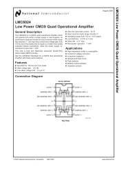
Figure 1 shows a block diagram of the internal circuitry integrated on the stand–alone<br />
sensing chip.<br />
Features<br />
• Temperature Compensated Over 0 to 85°C<br />
• Ideally Suited for Microprocessor or Microcontroller–Based Systems<br />
• Patented Silicon Shear Stress Strain Gauge<br />
• Durable Epoxy Unibody Element<br />
V S<br />
3<br />
1<br />
2<br />
3<br />
<br />
X–ducer<br />
SILICON<br />
PRESSURE SENSORS<br />
BASIC CHIP<br />
CARRIER ELEMENT<br />
CASE 867–08, STYLE 1<br />
PIN NUMBER<br />
Vout<br />
Gnd<br />
VS<br />
4<br />
5<br />
6<br />
N/C<br />
N/C<br />
N/C<br />
X–ducer<br />
SENSING<br />
ELEMENT<br />
THIN FILM<br />
TEMPERATURE<br />
COMPENSATION<br />
AND<br />
GAIN STAGE #1<br />
GAIN STAGE #2<br />
AND<br />
GROUND<br />
REFERENCE<br />
SHIFT CIRCUITRY<br />
1 Vout<br />
NOTE: Pins 4, 5, and 6 are internal<br />
device connections. Do not connect<br />
to external circuitry or ground. Pin 1<br />
is noted by the notch in the Lead.<br />
2<br />
PINS 4, 5 AND 6 ARE NO CONNECTS<br />
GND<br />
Figure 1. Fully Integrated Pressure Sensor Schematic<br />
MAXIMUM RATINGS(1)<br />
Parametrics Symbol Value Unit<br />
Overpressure(2) (P1 > P2) Pmax 4000 kPa<br />
Burst Pressure(2) (P1 > P2) Pburst 6000 kPa<br />
Storage Temperature Tstg –40° to +150 °C<br />
Operating Temperature TA –40° to +125 °C<br />
1. TC = 25°C unless otherwise noted. Maximum Ratings apply to Case 867–08 only.<br />
2. Extended exposure at the specified limits may cause permanent damage or degradation to the device.<br />
3. This sensor is designed for applications where P1 is always greater than, or equal to P2.<br />
Senseon and X–ducer are trademarks of Motorola, Inc.<br />
(Replaces MPX5999)<br />
Motorola Sensor Device Data<br />
© Motorola, Inc. 1997<br />
1
OPERATING CHARACTERISTICS (VS = 5.0 Vdc, TA = 25°C unless otherwise noted, P1 > P2)<br />
Characteristic Symbol Min Typ Max Unit<br />
Pressure Range(1) POP 0 — 1000 kPa<br />
Supply Voltage(2) VS 4.75 5.0 5.25 Vdc<br />
Supply Current Io — 7.0 10 mAdc<br />
Zero Pressure Offset(3) (0 to 85°C) Voff 0.088 0.2 0.313 Vdc<br />
Full Scale Output(4) (0 to 85°C) VFSO 4.587 4.7 4.813 Vdc<br />
Full Scale Span(5) (0 to 85°C) VFSS — 4.5 — Vdc<br />
Sensitivity V/P — 4.5 — mV/kPa<br />
Accuracy(6) (0 to 85°C) — — — ± 2.5 %VFSS<br />
Response Time(7) tR — 1.0 — ms<br />
Output Source Current at Full Scale Output IO+ — 0.1 — mA<br />
Warm–Up(8) — — 20 — Sec<br />
MECHANICAL CHARACTERISTICS<br />
Characteristic Symbol Min Typ Max Unit<br />
Weight, Basic Element (Case 867) — — 4.0 — Grams<br />
Cavity Volume — — — 0.01 IN3<br />
Volumetric Displacement — — — 0.001 IN3<br />
NOTES:<br />
1. 1.0 kPa (kiloPascal) equals 0.145 psi.<br />
2. Device is ratiometric within this specified excitation range.<br />
3. Offset (Voff) is defined as the output voltage at the minimum rated pressure.<br />
4. Full Scale Output (VFSO) is defined as the output voltage at the maximum or full rated pressure.<br />
5. Full Scale Span (VFSS) is defined as the algebraic difference between the output voltage at full rated pressure and the output voltage at the<br />
minimum rated pressure.<br />
6. Accuracy (error budget) consists of the following:<br />
• Linearity: Output deviation from a straight line relationship with pressure over the specified pressure range.<br />
• Temperature Hysteresis: Output deviation at any temperature within the operating temperature range, after the temperature is<br />
cycled to and from the minimum or maximum operating temperature points, with zero differential pressure<br />
applied.<br />
• Pressure Hysteresis: Output deviation at any pressure within the specified range, when this pressure is cycled to and from the<br />
minimum or maximum rated pressure, at 25°C.<br />
• TcSpan: Output deviation over the temperature range of 0° to 85°C, relative to 25°C.<br />
• TcOffset: Output deviation with minimum rated pressure applied, over the temperature range of 0° to 85°C, relative<br />
to 25°C.<br />
• Variation from Nominal: The variation from nominal values, for Offset or Full Scale Span, as a percent of VFSS, at 25°C.<br />
7. Response Time is defined as the time for the incremental change in the output to go from 10% to 90% of its final value when subjected to<br />
a specified step change in pressure.<br />
8. Warm–up is defined as the time required for the device to meet the specified output voltage after the pressure has been stabilized.<br />
9. P2 max is 500 kPa.<br />
2 Motorola Sensor Device Data
ON–CHIP TEMPERATURE COMPENSATION, CALIBRATION AND SIGNAL CONDITIONING<br />
<br />
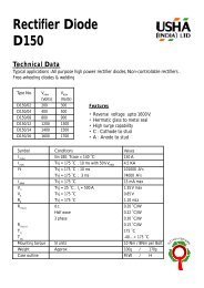
Figure 2 shows the sensor output signal relative to pressure<br />
input. Typical, minimum and maximum output curves<br />
are shown for operation over 0°C to 85°C. (Device output<br />
may be nonlinear outside of the rated pressure range.)<br />
The performance over temperature is achieved by integrating<br />
the shear–stress strain gauge, temperature compensation,<br />
calibration and signal conditioning circuitry onto a single<br />
monolithic chip.<br />
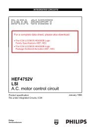
Figure 3 illustrates the differential or gauge configuration in<br />
the basic chip carrier (Case 867). A fluoro silicone gel isolates<br />
the die surface and wire bonds from harsh environments,<br />
while allowing the pressure signal to be transmitted to the<br />
silicon diaphragm.<br />
The <strong>MPX5999D</strong> pressure sensor operating characteristics,<br />
and internal reliability and qualification tests are based on use<br />
of dry air as the pressure media. Media other than dry air may<br />
have adverse effects on sensor performance and long–term<br />
reliability. Contact the factory for information regarding media<br />
compatibility in your application.<br />
Figure 4 shows a typical decoupling circuit for interfacing<br />
the output of the <strong>MPX5999D</strong> to the A/D microprocessor.<br />
Proper decoupling of the power supply is recommended.<br />
OUTPUT (V)<br />
5.0<br />
4.5<br />
4.0<br />
3.5<br />
3.0<br />
2.5<br />
2.0<br />
1.5<br />
TRANSFER FUNCTION:<br />
Vout = VS*(0.000901*P+0.04) ± ERROR<br />
VS = 5.0 Vdc<br />
TEMP = 0 to 85°C<br />
MAX<br />
MIN<br />
TYPICAL<br />
1.0<br />
0.5<br />
0<br />
0<br />
100<br />
200 300 400 500 600 700 800<br />
DIFFERENTIAL PRESSURE (kPa)<br />
900<br />
1000<br />
1100<br />
Figure 2. Output versus Pressure Differential<br />
WIRE BOND<br />
SILICONE<br />
DIE COAT<br />
DIE<br />
P1<br />
STAINLESS STEEL<br />
METAL COVER<br />
ÉÉÉÉÉÉÉÉÉÉÉÉ<br />
ÉÉÉÉÉÉÉÉÉÉÉÉ<br />
<strong>MPX5999D</strong><br />
OUTPUT<br />
(PIN 1)<br />
50 pF<br />
51 k<br />
A/D<br />
µ PROCESSOR<br />
LEAD<br />
FRAME<br />
P2<br />
THERMOPLASTIC CASE<br />
ÉÉÉÉÉÉÉÉÉÉÉÉ<br />
ÉÉÉÉÉÉÉÉÉÉÉÉ<br />
Figure 3. Cross–Sectional Diagram<br />
(Not to Scale)<br />
RTV DIE<br />
BOND<br />
Figure 4. Typical Decoupling Filter for Sensor to<br />
Microprocessor Interface<br />
Motorola Sensor Device Data<br />
3
PRESSURE (P1) / VACUUM (P2) SIDE IDENTIFICATION TABLE<br />
Motorola designates the two sides of the pressure sensor<br />
as the Pressure (P1) side and the Vacuum (P2) side. The<br />
Pressure (P1) side is the side containing fluoro silicone gel<br />
which protects the die from harsh media. The Motorola MPX<br />
pressure sensor is designed to operate with positive differential<br />
pressure applied, P1 > P2.<br />
The Pressure (P1) side may be identified by using the<br />
table below:<br />
Part Number<br />
Case Type<br />
<strong>MPX5999D</strong> 867–08 Stainless Steel Cap<br />
Pressure (P1)<br />
Side Identifier<br />
ORDERING INFORMATION<br />
The <strong>MPX5999D</strong> pressure sensor is available as an element only.<br />
MPX Series<br />
Device Type Options Case Type Order Number Device Marking<br />
Basic Element Differential 867–08 <strong>MPX5999D</strong> <strong>MPX5999D</strong><br />
4 Motorola Sensor Device Data
PACKAGE DIMENSIONS<br />
B<br />
J<br />
S<br />
C<br />
M<br />
–A–<br />
SEATING<br />
PLANE<br />
PIN 1<br />
–T–<br />
F<br />
R<br />
1 2 3 4 5 6<br />
D 6 PL<br />
G<br />
N<br />
POSITIVE PRESSURE<br />
(P1)<br />
L<br />
0.136 (0.005) M T<br />
A<br />
M<br />
NOTES:<br />
1. DIMENSIONING AND TOLERANCING PER ANSI<br />
Y14.5M, 1982.<br />
2. CONTROLLING DIMENSION: INCH.<br />
3. DIMENSION –A– IS INCLUSIVE OF THE MOLD<br />
STOP RING. MOLD STOP RING NOT TO EXCEED<br />
16.00 (0.630).<br />
INCHES MILLIMETERS<br />
DIM MIN MAX MIN MAX<br />
A 0.595 0.630 15.11 16.00<br />
B 0.514 0.534 13.06 13.56<br />
C 0.200 0.220 5.08 5.59<br />
D 0.027 0.033 0.68 0.84<br />
F 0.048 0.064 1.22 1.63<br />
G 0.100 BSC 2.54 BSC<br />
J 0.014 0.016 0.36 0.40<br />
L 0.695 0.725 17.65 18.42<br />
M 30 NOM 30 NOM<br />
N 0.475 0.495 12.07 12.57<br />
R 0.430 0.450 10.92 11.43<br />
S 0.090 0.105 2.29 2.66<br />
CASE 867–08<br />
ISSUE N<br />
STYLE 1:<br />
PIN 1. VOUT<br />
2. GROUND<br />
3. VCC<br />
4. V1<br />
5. V2<br />
6. VEX<br />
BASIC ELEMENT (A, D)<br />
Motorola Sensor Device Data<br />
5
Motorola reserves the right to make changes without further notice to any products herein. Motorola makes no warranty, representation or guarantee regarding<br />
the suitability of its products for any particular purpose, nor does Motorola assume any liability arising out of the application or use of any product or circuit, and<br />
specifically disclaims any and all liability, including without limitation consequential or incidental damages. “Typical” parameters which may be provided in Motorola<br />
data sheets and/or specifications can and do vary in different applications and actual performance may vary over time. All operating parameters, including “Typicals”<br />
must be validated for each customer application by customer’s technical experts. Motorola does not convey any license under its patent rights nor the rights of<br />
others. Motorola products are not designed, intended, or authorized for use as components in systems intended for surgical implant into the body, or other<br />
applications intended to support or sustain life, or for any other application in which the failure of the Motorola product could create a situation where personal injury<br />
or death may occur. Should Buyer purchase or use Motorola products for any such unintended or unauthorized application, Buyer shall indemnify and hold Motorola<br />
and its officers, employees, subsidiaries, affiliates, and distributors harmless against all claims, costs, damages, and expenses, and reasonable attorney fees<br />
arising out of, directly or indirectly, any claim of personal injury or death associated with such unintended or unauthorized use, even if such claim alleges that<br />
Motorola was negligent regarding the design or manufacture of the part. Motorola and are registered trademarks of Motorola, Inc. Motorola, Inc. is an Equal<br />
Opportunity/Affirmative Action Employer.<br />
Mfax is a trademark of Motorola, Inc.<br />
How to reach us:<br />
USA / EUROPE / Locations Not Listed: Motorola Literature Distribution; JAPAN: Nippon Motorola Ltd.; Tatsumi–SPD–JLDC, 6F Seibu–Butsuryu–Center,<br />
P.O. Box 5405, Denver, Colorado 80217. 303–675–2140 or 1–800–441–2447 3–14–2 Tatsumi Koto–Ku, Tokyo 135, Japan. 81–3–3521–8315<br />
Mfax: RMFAX0@email.sps.mot.com – TOUCHTONE 602–244–6609 ASIA/PACIFIC: Motorola Semiconductors H.K. Ltd.; 8B Tai Ping Industrial Park,<br />
– US & Canada ONLY 1–800–774–1848 51 Ting Kok Road, Tai Po, N.T., Hong Kong. 852–26629298<br />
INTERNET: http://motorola.com/sps<br />
6 ◊<br />
Motorola Sensor <strong>MPX5999D</strong>/D Device Data