Ty Smith. CEMTEK - MARAMA
Ty Smith. CEMTEK - MARAMA
Ty Smith. CEMTEK - MARAMA
Create successful ePaper yourself
Turn your PDF publications into a flip-book with our unique Google optimized e-Paper software.
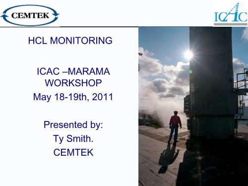
HCL MONITORING<br />
ICAC –<strong>MARAMA</strong><br />
WORKSHOP<br />
May 18-19th, 2011<br />
Presented by:<br />
<strong>Ty</strong> <strong>Smith</strong>.<br />
<strong>CEMTEK</strong><br />
1
HCL MONITORING<br />
Applications<br />
Existing Measurement Technologies<br />
New Technologies<br />
Calibration and issues<br />
2
APPLICATION EMISSION REQUIREMENTS<br />
CEMENT :<br />
•Fuel type- coal, biomass, gas.<br />
•MACT Limit – 3ppmvd@7%O2<br />
•Requires CEMS<br />
UTILITY :<br />
•Fuel type - Coal<br />
•Proposed MACT Limit – 0.2 lbs/MMBtu<br />
• Will Require CEMS<br />
WASTE INCINERATION:<br />
•Fuel <strong>Ty</strong>pe - Biomass<br />
•SIP Emission Limit – 29ppmvd@7%O2 (for affected facilities)<br />
• May require CEMS, based on source.<br />
3
Application Requirements<br />
WET SAMPLING:<br />
Most applications and measurement methods require the use of wet<br />
sampling to avoid any issues that may compromise the sample<br />
When measuring a hot wet sample it prevents errors due to absorption,<br />
desorption effects from HCl on the wetted parts.<br />
Keep the entire sample train hot/insulated to prevent cold spots –<br />
Conventional Hot/wet systems require sample components be kept at a<br />
minimum of 185 o C to prevent cold spots.<br />
Low pressure sample systems should be kept above 50 C.<br />
Standard hot/wet systems sample at high temperature and high flow<br />
rate. –This shortens the time the sample is in contact with the system<br />
components, minimizing memory effects.<br />
Low pressure sample systems require no sample conditioning or<br />
moisture removal.<br />
4
Concerns<br />
Problems associated with Acid Gases:<br />
The sample has to be maintained above acid dew point (normally 140-<br />
150 o C)<br />
Chlorides not removed in the particulate filter can cause interference<br />
problems .<br />
NH3 can cause interference.<br />
Biggest problem with stability is keeping moisture from reaching the<br />
gas.<br />
N2 purge on the pressure side is recommended to insure that ambient<br />
H2O does not mix with the gas.<br />
5
MEASUREMENT TECHNIQUES<br />
FTIR: Fourier Transform IR<br />
NDIR: Non Dispersive IR<br />
----------------------------<br />
TDL: Tunable Diode Laser - Cross Duct<br />
Extractive <strong>Ty</strong>pe - Optical Feedback Laser<br />
6
MEASUREMENT TECHNIQUES<br />
FTIR: Fourier Transform IR Technique utilizes a moving mirror in an<br />
interferometer to generate an “interferogram” of the sample absorption<br />
spectrum<br />
Performing a mathematical Fourier transform on the “interferogram”<br />
generates a single beam spectrum.<br />
The single beam spectrum must be routinely ratioed against a zero<br />
gas single beam spectrum to compensate for drift & linearize<br />
instrumental response.<br />
FTIR can generate multi-component measurement results, including<br />
HCl.<br />
Hot wet sample system<br />
Internal gas cell available.<br />
<strong>Ty</strong>pical minimum range for HCl: 0-10ppm<br />
7
Measurement Technique<br />
What is Fourier Transform Infrared Spectroscopy (FTIR)<br />
• Measurement technique collects all of the infrared spectral data at once.<br />
• A broadband IR light is sent through the interferometer (modulator) which<br />
modulates all of the light wavelengths at once.<br />
• Once modulated, the signal is passed through the gas cell where various<br />
molecules absorb some of the light.<br />
• The measured signal is demodulated, using the Fourier Transform<br />
process, which converts the mirror position into a frequency response<br />
that is directly related to the molecules present in the gas sample.
Measurement Technique<br />
Fourier Transform Infrared (FTIR) Data Analysis<br />
• The demodulated signal (interferogram) is converted via the Fast Fourier<br />
Transform (FFT) to a single beam spectrum.<br />
• To remove the FTIR instrument response, a non-IR absorbing gas is<br />
passed through the gas cell prior to flowing the sample. This instrument<br />
response is removed from the sample signal during the sample process.<br />
• A logarithmic ratio of the sample beam to the background beam produces<br />
the final Absorbance signal over the IR spectrum and contains the<br />
response of all compounds that are IR active.<br />
• The height of the Absorbance peak is directly related to the concentration.
Measurement Technique<br />
NDIR:<br />
• Non-dispersive or filter-based IR systems utilize either the “Dual<br />
Wavelength / Filter” or “Gas Filter Correlation (GFC)”, Cross Flow<br />
Modulation techniques to measure gas components. For HCL,<br />
GFC is the technique of choice for some CEMS suppliers<br />
• both sample and reference filters are swung into the light path. In<br />
the case of the reference filter, typically nitrogen,or some other gas<br />
with no absorbance in the IR region, is passed through the gas<br />
cell, leaving a baseline background for comparison. Then the<br />
sample gas is run through the gas cell and the sample filter is<br />
swung into the light path allowing only a narrow band of light at a<br />
specific wavelength region to pass through to the detector,<br />
measuring the absorption of the gas that is specific for that filter in<br />
question. The background interference is eliminated by ratioing the<br />
sample absorbance to that of the reference (N2) absorbance, as<br />
they are present in both spectrum.<br />
• The NDIR can monitor additional gases such as NO, NO2, CO2,<br />
CO, SO2 and others by the application of multiple filters tuned to<br />
those compounds, providing a more versatile analysis instrument .
Measurement Technique<br />
NDIR GAS FILTER CORRELATION<br />
<strong>Ty</strong>pical GFC configuration<br />
11
HOT WET SAMPLING<br />
Sick MCS-100.<br />
HCl module can be added to existing systems.<br />
Similar to other NDIR systems.<br />
12
Are there other options<br />
• Yes there are!<br />
13
Can We Do Better<br />
• We don’t believe that existing FTIR & NDIR<br />
analyzer systems are able to accurately measure<br />
the low levels HCl that the rules will require.<br />
• What other options are available<br />
• Can these newer analyzers be more accurate,<br />
require less maintenance and still be cost<br />
effective<br />
• Accurate analyzers are needed to maximize<br />
effectiveness of scrubbing systems and reduce<br />
the amount of scrubber media required.<br />
14
What are the options<br />
• Option 1:<br />
• Cross Duct TDL’s<br />
• Utilize existing TDL technology used for NH3 and<br />
other gasses to measure HCl.<br />
• Several successful installations measuring less<br />
than 2ppm HCl.<br />
• How do they work<br />
15
Tunable Diode Laser<br />
Measurement Technique<br />
Measurement method<br />
Very accurate method for measuring emissions of HCL.<br />
Several different configurations offer flexibility depending on<br />
application.<br />
Across Stack Analyzer: non contact sampling, measures<br />
flue gas in its natural condition<br />
Purge air or blowers to keep optics clean.<br />
Shorter path lengths required in high particulate<br />
applications.<br />
No Zero Drift. Built in Span Calibration Cell.<br />
16
Tunable Diode Laser<br />
Measurement Technique<br />
How do Tunable Diode Lasers (TDL)<br />
Operate<br />
• Laser center wavelength depends on composition of<br />
crystal<br />
• Laser wavelength can be changed over narrow range by<br />
changing current or over a wider range by changing<br />
laser operating temperature<br />
• By temperature controlling the laser, changing the<br />
electric current permits scanning over entire absorption<br />
feature<br />
• By scanning the entire absorption feature, interference<br />
from dust is eliminated as the laser signal power is<br />
continuously measured.
Across Stack TDL Analysis<br />
DUCT<br />
Fiber-optic<br />
& coax cables<br />
Analyzer
Across Stack TDL Analysis<br />
CALIBRATION<br />
Internal Calibration Cells<br />
19
Daily Calibration:<br />
Across Stack TDL Analysis<br />
Calibration Capabilities:<br />
•Calibration check using Internal Cal Cell.<br />
•Checks Zero by analyzing background signal<br />
• Span Cal value typically 20ppm<br />
•Timing controlled by Analyzer<br />
Additional Calibration Verification Option:<br />
•Calibration using Inline Flow –Thru’ Cell<br />
•Zero Air purge for cell to ensure no false indication, Zero<br />
check as per daily cal check<br />
•Span gas flow thru’ (approx 8 minutes, 3 for stabilization, 5<br />
for detection)<br />
20
SECOND OPTION<br />
• Optical Feedback Cavity Enhanced Absorption<br />
Spectroscopy.<br />
• The challenge was developing a sampling<br />
method that would allow this technology to be<br />
used in almost any application.<br />
• This lead to Patented Low Pressure Sampling<br />
Technology being used from probe to analyzer.<br />
• No sample conditioning required.<br />
• No interference from other gasses or moisture.<br />
21
<strong>CEMTEK</strong> OFL-CEM for HCl<br />
22
Extractive OFL-CEM Analyzer<br />
• Utilizing the latest advancements in Scanning Laser<br />
Analyzer technology. Optical Feedback improves<br />
analytical performances in terms of accuracy, stability &<br />
sensitivity.<br />
• Up to 20 KM path length allows for PPM, PPB & in some<br />
cases PPT measurements.<br />
• Optical Feedback stabilizes the spectrometer by<br />
monitoring & compensating for source variations in the<br />
optical system & monitoring in real time (10Hz) the output<br />
signal of the spectrometer to automatically correct for any<br />
drift.<br />
23
OFL-CEM Analyzer<br />
• Optical Feedback improves laser accuracy 100x,<br />
reducing noise & interference & increases<br />
sensitivity by 1,000 x over standard metric gas<br />
cells by increasing path length a thousand fold.<br />
• Low pressure sampling in the gas cell narrows<br />
the absorption bands to a point where no<br />
spectral overlapping occurs.<br />
• Range of 0-3ppm with 30 ppb accuracy<br />
24
Low pressure sampling probe<br />
25
Optical Feedback Cavity Enhanced Absorption Spectroscopy<br />
+ Low Pressure Sampling for HCl (g) Measurement<br />
A Scanning TDL or QCL<br />
B Hyper-Reflective Gas Cell<br />
C Detector - high speed<br />
D Beam splitter<br />
E Detector<br />
F Sampling Probe<br />
G Vacuum Pump<br />
- 200 data points spectra @ 1 picometer resolution<br />
- up to 20km path length equivalent<br />
- (100 msec. scan) High MTBF<br />
- Rugged, non-hygroscopic optics<br />
- high MTBF<br />
- low flow rate, low fouling sonic nozzle<br />
- cost effective, low maintenance<br />
26
LOW PRESSURE SAMPLING<br />
1 Laser - Multiple Gases (50 mbar – 45°C – 10 km<br />
50-100 mbar<br />
Patented LPS<br />
sampling<br />
10% H2O<br />
1ppm HCL<br />
10% H2O<br />
NO 1000PPM<br />
No Spectral Overlapping (@ 50-100 mbar)<br />
=<br />
No Possible Cross Response / Interference<br />
Can be used to measure H2O, NO, CO, CO2,<br />
H2S, NH3, SO3, CH4, N2O, CO3, O3, Methanol's etc.<br />
27
LOW PRESSURE SAMPLING<br />
Lowering the pressure of a gas sample therefore also reduces the dew point of all<br />
chemicals present.<br />
A flow rate of 3 l/h results in extremely low fouling – est. 4g deposit over a 12<br />
month period.<br />
Because H2O remains in gas phase there is no spectrally overlapping, unlike in<br />
most FTIR’s where spectral overlapping can occur.<br />
Additional particulate filters ensure that the gas cell remains clean.<br />
28
CALIBRATION<br />
Self-referencing spectrometer – No zero gas required<br />
Zero Reference Information is<br />
contained in the signal itself.<br />
Raw Spectrum<br />
Calibration Method: Beer-<br />
Lambert’s Law<br />
Can be verified with calibration<br />
gas at the probe tip or directly into<br />
the analyzer.<br />
N.I.S.T Traceable direct<br />
measurement.<br />
I 0 (ZERO)<br />
I (conc.)<br />
0.00112nm<br />
0.005cm-1<br />
29
CALIBRATION<br />
Calibration Gas Requirements:<br />
Keep Calibration gas cylinders and associated hardware<br />
dry<br />
Cylinders should have nickel coating on the walls<br />
Pressure regulators must be nickel lined stainless steel,<br />
No protocol gas at present. EPA & manufacturers in<br />
discussion on this.<br />
Cylinders available in the range of 10ppm and higher.<br />
Keep all moisture out of regulator & cal lines.<br />
30
CALIBRATION<br />
Calibration Gas Issues:<br />
Biggest issue is moisture in the sample and sample line.<br />
Sample temperature should be maintained above 180C, for<br />
FTIR & NDIR Systems.<br />
Should be kept above 50 C for OFL-CEM Systems.<br />
Keep Calibration gas cylinders and associated hardware<br />
dry<br />
The OF-CEAS analyzer system eliminates the typical<br />
calibration issues of instability.<br />
Recommend using silica coated probes and silica coated<br />
stainless steel tubes for sample & calibration gas.<br />
.<br />
31
QUESTIONS <br />
Thank you for your time this morning, for more information<br />
contact:<br />
<strong>Ty</strong> <strong>Smith</strong><br />
President<br />
<strong>CEMTEK</strong> GROUP<br />
Ph: (908) 474-9630<br />
ty@cemteks.com<br />
Acknowledgements to:<br />
Dan Kietzer - Sick Optics<br />
Alak Chandra – Unisearch<br />
Lucien Lonigro – AP2E<br />
Bertrand Lahner – Sensors Inc.<br />
Ken Greaves<br />
National Sales Manager<br />
<strong>CEMTEK</strong> INSTRUMENTS<br />
Ph: (215) 290-4593<br />
kgreaves@cemteks.com<br />
32


