55-64 Full Size Chevy - Right Stuff Detailing
55-64 Full Size Chevy - Right Stuff Detailing
55-64 Full Size Chevy - Right Stuff Detailing

You also want an ePaper? Increase the reach of your titles
YUMPU automatically turns print PDFs into web optimized ePapers that Google loves.
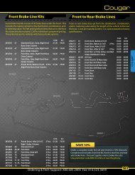
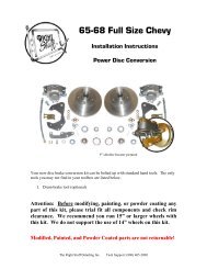
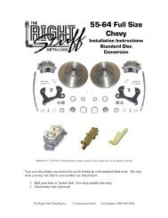
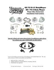
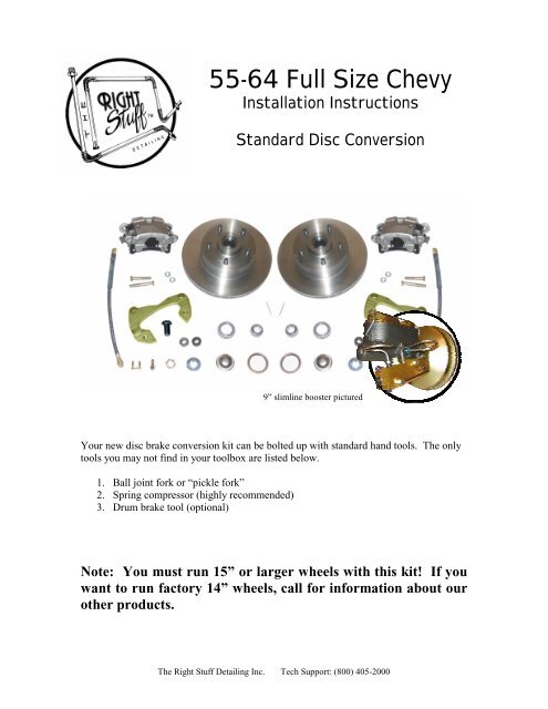
<strong>55</strong>-<strong>64</strong> <strong>Full</strong> <strong>Size</strong> <strong>Chevy</strong><br />
Installation Instructions<br />
Standard Disc Conversion<br />
9” slimline booster pictured<br />
Your new disc brake conversion kit can be bolted up with standard hand tools. The only<br />
tools you may not find in your toolbox are listed below.<br />
1. Ball joint fork or “pickle fork”<br />
2. Spring compressor (highly recommended)<br />
3. Drum brake tool (optional)<br />
Note: You must run 15” or larger wheels with this kit! If you<br />
want to run factory 14” wheels, call for information about our<br />
other products.<br />
The <strong>Right</strong> <strong>Stuff</strong> <strong>Detailing</strong> Inc. Tech Support: (800) 405-2000
Lower Assembly<br />
1. Prepare the car<br />
Begin by securely supporting the car on jack stands. Chock the rear wheels and set the<br />
parking brake to be sure vehicle does not roll. Always work on a flat, even surface.<br />
Remove the wheels to gain access to the brake system.<br />
2. Disconnect tie rod ends<br />
Remove the cotter pin and castle nut that secures the tie rod to the steering arm. You will<br />
reuse the castle nuts later. Use a heavy hammer to remove the tie rod end from the<br />
steering arm. A ball joint fork or “pickle fork” may be needed to break things loose.<br />
3. Disconnect front flex hoses<br />
Unscrew the hard line from the flex hose, being careful not to get brake fluid on painted<br />
surfaces. Remove the flex hose retaining clip and pull the hose out of the frame mounted<br />
bracket.<br />
4. Remove drum brake assemblies<br />
Remove the original drum brake hardware from the spindle. You should also unbolt the<br />
steering arms at this time.<br />
5. Inspect suspension components<br />
Now is the time to clean up and inspect your suspension components. Check the inner<br />
and outer tie rod ends and ball joints for wear and replace if needed. Inspect the rubber<br />
boots for cracks or tears. Universal replacements are available at most automotive parts<br />
stores.<br />
The <strong>Right</strong> <strong>Stuff</strong> <strong>Detailing</strong> Inc. Tech Support: (800) 405-2000
6. Install the caliper brackets and steering arms<br />
Install the appropriate caliper bracket onto the spindle and hold it in place with the<br />
special 5/8” bolt. ’59 – ’<strong>64</strong> owners need to use the large diameter washer to space the<br />
bracket out away from the spindle.<br />
Note: The opening for the caliper should face towards the rear of the car. Left is driver’s<br />
side, right is passenger’s side.<br />
Reinstall your old steering arm using the new bolts. Use the small diameter washer to<br />
space out the front steering arm bolt. Place the tie rod end back into the steering arm and<br />
fasten it with the original castle nut. Torque the nut to the specifications provided in the<br />
assembly manual. Fix it in place with the new cotter pin supplied with your kit.<br />
’59-’<strong>64</strong> Spacer<br />
Steering Arm Spacer<br />
7. Grease the bearings and install the rotors<br />
You are now ready to install the bearings and rotor. Start by placing the rotor face down.<br />
Races come preinstalled in the rotors. If you received additional races with your<br />
bearings, they will not be used. Apply a little bearing grease to the bearing race already<br />
in the rotor and pack the larger of the two bearings (Inner) with grease. Install the<br />
bearing into the rotor and place the grease seal on the rotor. Tap the seal into place being<br />
careful not to damage the rubber portion of the seal.<br />
The <strong>Right</strong> <strong>Stuff</strong> <strong>Detailing</strong> Inc. Tech Support: (800) 405-2000
Inner Bearing Assembly<br />
Outer Bearing Assembly<br />
Note: Drilled and/or slotted rotors are directional. Be sure you have the appropriate rotor<br />
for the side of the car you are working on. Left is driver’s side, right is passenger’s side.<br />
Turn the rotor face up and grease the bearing race. Pack the smaller bearing (Outer) and<br />
place it in the rotor. Slide the rotor onto the spindle being careful that the outer bearing<br />
does not fall out of place. Install the keyed washer and castle nut and torque to the<br />
specifications provided in the assembly manual. Fix it in place with the new cotter pin<br />
supplied with your kit. Install the dust cap with a mallet and a large socket placed over<br />
the dust cap. A screwdriver can also be used along the edges.<br />
8. Mount the calipers and flex hose<br />
Your new calipers come fully loaded with pads, bolts, and copper washers. Start by<br />
removing the caliper pins and position the caliper in the bracket with the bleeder screw at<br />
the 12 o’clock position. If the caliper won’t install in the brackets with the bleeder<br />
pointed up, you probably have the opposite side caliper. Insert the caliper pins and<br />
torque to the specifications provided in the assembly manual. Due to variations in brake<br />
pads, you may need to modify the wear sensor to clear the caliper bracket.<br />
Note: The bleeder screws must be pointed up. If the bleeders are pointed down, the<br />
calipers will trap air and you will not get the system to bleed properly.<br />
Remove the banjo bolt and copper washers from the caliper. Place a copper washer on<br />
top of the flex hose and insert the banjo bolt. Place the second copper washer over the<br />
banjo bolt on the bottom of the flex hose and bolt the hose onto the caliper with the<br />
specifications provided in the assembly manual.<br />
The <strong>Right</strong> <strong>Stuff</strong> <strong>Detailing</strong> Inc. Tech Support: (800) 405-2000
Note: Make sure the flex hose seats square against the caliper. You may need to flip the<br />
hose over.<br />
Insert the other end of the flex hose into your original frame brackets. You may need to<br />
file the inside of your original brackets to accommodate the new flex hose. Push on the<br />
new flex hose clip supplied with your kit. At this point the hose might seem a little tight<br />
when you turn the wheels from lock to lock. This is normal. The suspension is flexed to<br />
the absolute limits of its travel. You would have to be airborne while making a sharp turn<br />
to recreate these conditions while driving.<br />
The <strong>Right</strong> <strong>Stuff</strong> <strong>Detailing</strong> Inc. Tech Support: (800) 405-2000
Upper Assembly<br />
1. Remove the old master cylinder assembly<br />
Remove the master cylinder brake lines being careful not to get fluid on any painted<br />
surfaces. Remove the clevis from the pedal rod under the dash. If your original system<br />
was power, you should be able to remove the booster mounting nuts from the firewall and<br />
remove the booster/master assembly. If your original system was not power, simply<br />
remove the master cylinder mounting nuts from the firewall and remove the master<br />
cylinder.<br />
2. Mount the new master cylinder<br />
a. Place the master cylinder over the top two studs on the firewall and hold it in<br />
place with nut on the passenger’s side.<br />
b. Slide the valve bracket over the driver’s side stud and loosely tighten it down<br />
with the nut.<br />
Note: Leave the mounting nuts a little loose at this point. It makes the lines much<br />
easier to install if there is a little play in the bracket.<br />
c. Bolt the proportioning valve to the outside (driver’s side) of the bracket with<br />
the hardware supplied in your kit.<br />
d. Now you’re ready to install the master cylinder lines. If you purchased lines<br />
with your conversion kit, the two small loop lines are the master cylinder<br />
lines.<br />
e. Tighten the nuts up on the firewall<br />
3. Install and adjust the pedal rod<br />
Insert the rod and clevis assembly into the master cylinder. You can reuse your old rod<br />
or use the universal unit that came with your kit. You may need to cut the universal rod<br />
to suite your application. Adjust the pedal rod so there is about ¼" of free travel at the<br />
top of the pedal. Be sure to tighten all jam nuts on the pedal rod to lock it in place after<br />
all your adjustments are made.<br />
The <strong>Right</strong> <strong>Stuff</strong> <strong>Detailing</strong> Inc. Tech Support: (800) 405-2000
Bleeding the system<br />
Working your way forward from the wheel farthest from the master cylinder will help<br />
insure a good bleed and a firm pedal. It is important to bleed the system in the following<br />
order:<br />
1. <strong>Right</strong> Rear<br />
2. Left Rear<br />
3. <strong>Right</strong> Front<br />
4. Left Front<br />
If you have a spongy pedal, be sure the bleeder screws are pointed up and try re-bleeding<br />
the system.<br />
Technical Support<br />
We want your conversion project to go smoothly. Double check that you have followed<br />
these instructions correctly and those included with any upgrade components you may<br />
have purchased. If you need additional help getting your new disc brakes to function<br />
properly, we’re here for you. Give us a call at (800) 405-2000 or you can email your<br />
questions including photos to tech@rightstuffdetailing.com<br />
Thank You for Your Business!<br />
No part of this document may be reproduced without written permission of The <strong>Right</strong> <strong>Stuff</strong> <strong>Detailing</strong> Inc. The information contained in this document<br />
is based on information we believe to be true and reliable, however the accuracy or completeness thereof is not guaranteed.<br />
The <strong>Right</strong> <strong>Stuff</strong> <strong>Detailing</strong> Inc. Tech Support: (800) 405-2000
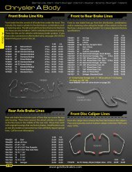
PV71 Fixed Combination Valve Supplement<br />
This supplement is for customers who have chosen the “fixed” combination valve with the<br />
purchase of our disc brake conversion kits. This diagram shows where each port of the valve<br />
routes. If you have any further questions or concerns, please don’t hesitate to call our toll free<br />
technical support line. Thank you again for your business.<br />
1/2" – 20 7/16” – 24<br />
To Front Master To Rear Master<br />
Cylinder Port<br />
Cylinder Port<br />
| |<br />
3/8” – 24 | |<br />
To Left or __<br />
<strong>Right</strong> Front<br />
__<br />
|<br />
|<br />
|<br />
9/16” – 18 |<br />
To Rear ___ |<br />
| Axle<br />
3/8” - 24<br />
To Left or<br />
<strong>Right</strong> Front<br />
The <strong>Right</strong> <strong>Stuff</strong> <strong>Detailing</strong> Inc. Tech Support: (800) 405-2000