Sieger System 57 - Detection & Measurement Systems
Sieger System 57 - Detection & Measurement Systems
Sieger System 57 - Detection & Measurement Systems

You also want an ePaper? Increase the reach of your titles
YUMPU automatically turns print PDFs into web optimized ePapers that Google loves.
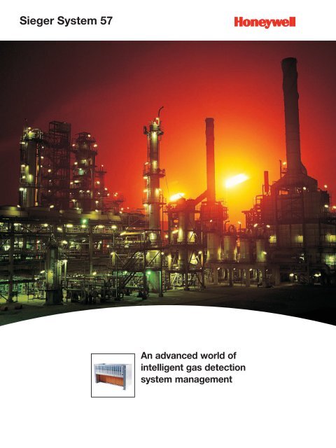
<strong>Sieger</strong> <strong>System</strong> <strong>57</strong><br />
An advanced world of<br />
intelligent gas detection<br />
system management
<strong>Sieger</strong> <strong>System</strong> <strong>57</strong><br />
A world of control technology<br />
• High precision, intelligent control<br />
• Master/voted alarm options<br />
• High packing density<br />
• Flexible I/O configuration<br />
• Relay output options<br />
<strong>System</strong> <strong>57</strong> - the heart of fire and gas control<br />
For almost half a century, <strong>Sieger</strong> gas detection<br />
systems have provided the safety needed to<br />
protect plant and personnel from flammable<br />
and toxic gas hazards. Across the globe, they<br />
are installed in a wide variety of applications<br />
ranging from simple small scale systems to<br />
some of the world’s largest fully integrated fire<br />
and gas detection systems.<br />
To fulfil the unique requirements of each<br />
individual application requires a control system<br />
with unlimited flexibility. The modular design<br />
approach employed by the <strong>Sieger</strong> <strong>System</strong> <strong>57</strong><br />
enables you to define, in detail, the unique<br />
control and alarm parameters to fulfil your<br />
requirement.<br />
<strong>System</strong> <strong>57</strong> accepts inputs from flammable and<br />
toxic gas detectors, a large range of flame,<br />
smoke and heat detectors and manual call<br />
points. Available outputs include relays, analog<br />
signals and industry standard digital protocols.<br />
Packaged in either wall mounting cabinets or<br />
panel mounting racks, <strong>System</strong> <strong>57</strong> can be used<br />
stand alone or integrated into the heart of a fire<br />
and gas system.<br />
Whatever the application, large or small,<br />
our sales engineers and customer service<br />
representatives are available to discuss your<br />
requirements and recommend the control<br />
system that’s best for you.
Technical Summary<br />
<strong>57</strong>04F Fire Card Specification <strong>57</strong>04 Fire Card <strong>57</strong>04 Fire Status Panel<br />
Audible Sounder - 60dB at 1 meter<br />
Remote Facilities accept, reset and silence -<br />
Supply Voltage 21V to 32Vdc 18V to 32Vdc<br />
Power Consumption 2W 0.75W<br />
Operating Temperature<br />
-5ºC to +55ºC<br />
Storage Temperature<br />
-25ºC to +55ºC<br />
Operating Humidity<br />
20-90% RH (non condensing)<br />
Dimensions<br />
3U high x 25mm wide<br />
Weight 175g 75g<br />
Approvals<br />
EN50270<br />
Cabinets Racks and Power Supplies Specification<br />
Cabinets<br />
Material<br />
Mild Steel<br />
Colour<br />
RAL-7015 - slate grey<br />
Hinge<br />
Left hand side<br />
Lock<br />
Right hand side<br />
Rack Mounting<br />
8 way: half 19" profile.<br />
16 way: 19" universal profile<br />
Pre-formed Gland Entries 8 way: 2 x M25; 2 x PG16; 8 x M20; 6 x PG11<br />
16 way: 3 x M25; 4 x PG16; 16 x M20; 10 x PG11<br />
Environmental Protection IP54<br />
Mounting Plate<br />
8 way: 120mm high x 220mm wide<br />
16 way: 120 mm high x 440mm wide<br />
Earthing Points Main Cabinet: M6. Door: M5.<br />
Mounting Bracket Holes 10mm diameter<br />
Weight<br />
8 way: 10.0kg<br />
16 way: 13.5kg<br />
Racks<br />
Material<br />
Galvanized Steel<br />
Colour (Mounting Brackets) RAL-7015 - slate grey<br />
Mounting<br />
8 way: half 19" profile.<br />
16 way: 19" universal profile<br />
Earthing Point<br />
M5 stud<br />
Mounting Bracket Holes 6mm diameter<br />
Supply Voltage<br />
18 to 32Vdc<br />
Power Consumption 1.5W<br />
Operating Temperature<br />
-5ºC to +55ºC<br />
Storage Temperature<br />
-25ºC to +55ºC<br />
Operating Humidity<br />
0-90%RH (non-condensing)<br />
Cabinets Racks and Power Supplies Specification cont.<br />
Racks cont.<br />
Weight<br />
(inc. Engineering Card & DC input Card)<br />
Approvals<br />
Power Supplies<br />
Supply Voltage<br />
Inrush Current<br />
8 way front access 3.9kg<br />
16 way front access 5.8kg<br />
8 way rear access 2.8kg<br />
16 way rear access 4.1kg<br />
EN50270<br />
ac: 85V to 264V; 47Hz to 440Hz<br />
dc: 110V to 340V<br />
Output Voltage 24Vdc ± 10%<br />
Power Supply Rating<br />
Overload Protection<br />
Overvoltage Protection<br />
Mounting<br />
Earthing Point<br />
Mounting Bracket Holes<br />
Operating Temperature<br />
Operating Humidity<br />
Weight<br />
Colour<br />
Approvals<br />
typically 30A at 230V input for 50W full load<br />
8-way: 50W upgradeable to 100W<br />
16-way: 50W upgradeable to 200W<br />
Operates at more than 105% of rating.<br />
Recovery automatic.<br />
Operates at more than 115% of rating<br />
8 way: half 19" profile.<br />
16 way: 19" universal profile<br />
M5 stud<br />
6mm diameter<br />
-25ºC to +55ºC<br />
20-90%RH (non-condensing)<br />
8 way,50W 0.9kg<br />
16 way, 50W 0.96kg<br />
subunit: 815g<br />
50W module 230g<br />
Front: RAL-7015- slate grey<br />
Body: Black anodize<br />
EN50270<br />
Cabinets Racks and Power Supplies Dimension Drawings<br />
132.5<br />
(rear access)<br />
247 (8 way)<br />
450 (16 way)<br />
100<br />
8 way 367<br />
16 way <strong>57</strong>0<br />
41<br />
266<br />
(front access)<br />
279.4 (8 way)<br />
482.6 (16 way)<br />
287.6<br />
(rear access)<br />
217.6<br />
(front access)<br />
8 way 337<br />
16 way 540<br />
630 430<br />
100<br />
268 15 15<br />
279.4 (8 way)<br />
482.6 (16 way)<br />
220<br />
* Dimensions in mm
<strong>Sieger</strong> <strong>System</strong> <strong>57</strong><br />
1 <strong>57</strong>01 Gas Control Card<br />
This provides a single channel control function<br />
within a 1" wide package.<br />
• Independent single channel operation<br />
• Plug-in input and output options<br />
2 <strong>57</strong>04 Gas Control Card<br />
This provides four channels of control function<br />
within a 1" wide package.<br />
• 4-channel operation<br />
• Choice of output options<br />
• Channel displayed: automatic sequencing,<br />
highest reading, combination or manual<br />
channel display selection options<br />
3 <strong>57</strong>04f Fire Control Card<br />
This provides four zones of fire control within a<br />
1" wide package.<br />
• 4 zone fire card<br />
• 2 line monitored outputs<br />
• Up to 15 cards in a 19" rack<br />
4 <strong>57</strong>04fs Fire Status Panel<br />
Each rack that contains a <strong>57</strong>04F fire card<br />
has one <strong>57</strong>04FS fire status panel fitted. The<br />
<strong>57</strong>04FS fire status panel provides common<br />
display and alarm indication for all of the fire<br />
cards in a rack as well as a local audible<br />
sounder. It also provides common push<br />
buttons for executing specific fire card related<br />
functions.<br />
• Common fire control card push button<br />
functions<br />
• Common display and alarm indications<br />
5 Master Alarm Update Panel<br />
The master alarm update facility can be<br />
enhanced by adding the optional master alarm<br />
update panel.<br />
• 1" wide panel<br />
• Audible and visual alarm<br />
• Reset and accept push button<br />
• Provides update facilities without the need for<br />
external wiring<br />
6 Power Supply Units<br />
The power supply units are rack mounted to<br />
complement the <strong>System</strong> <strong>57</strong> systems<br />
• 1U high, 19" & 1/2 19" units<br />
• Upgradeable to 200W in 50W blocks<br />
• Auto sensing input voltage: AC or DC<br />
• Regulated DC output<br />
• Over voltage and overload protected<br />
7 Engineering Card<br />
The <strong>System</strong> <strong>57</strong> engineering card provides<br />
full maintenance and set up facilities for each<br />
channel card. The front panel has a series<br />
of tactile feedback push buttons that allows<br />
checks of the alarm levels and performance to<br />
be carried out for each channel. A real-time ‘on<br />
board’ clock provides calibration history and<br />
calibration overdue reminder functions.<br />
• Security protected<br />
• User friendly operation<br />
• Calibration facility<br />
• Command accept/abort facility<br />
• Channel card set up capability<br />
• Local audible sounder
<strong>Sieger</strong> <strong>System</strong> <strong>57</strong><br />
Optional analog<br />
output module<br />
6<br />
4 5<br />
1<br />
Analog input board<br />
Catalytic input board<br />
7<br />
2<br />
9<br />
9<br />
10<br />
3<br />
8<br />
10<br />
Blank panel
<strong>Sieger</strong> <strong>System</strong> <strong>57</strong><br />
8 Engineering Card Modules<br />
A number of plug-in options for the extended<br />
system capabilities:<br />
8a Serial Communications Module<br />
The serial communications module provides a<br />
gateway between the <strong>System</strong> <strong>57</strong> rack and a<br />
remote device (DCS, PLC or SCADA package)<br />
to allow the continuous monitoring of each<br />
channel’s operation and condition as well as<br />
allowing remote configuration of the system<br />
operation.<br />
• Industry standard MODBUS RTU protocol<br />
• RS485/422/232 standard<br />
• Bi-directional<br />
• Electrically isolated communications bus<br />
• SCADA graphics package available<br />
8b Rs232 Printer Driver Module<br />
The printer driver module provides a serial<br />
output in the event of a gas alarm, fault or user<br />
intervention.<br />
• RS232 ASCII event data<br />
• Selectable print criteria<br />
• Time and date stamping<br />
• Electrically isolated communications bus<br />
8c Master Alarm Update Module<br />
The alarm update module provides a common<br />
alarm indication with new alarm event update.<br />
• 2 Outputs: 1 relay, 1 Darlington<br />
• Selectable operation: pulsed, continuous<br />
• Alarm accept input<br />
• Common alarm reset input<br />
• Complies with ISA ‘M’, DIN 19 235<br />
• Optional master alarm update panel<br />
9 Interface Cards<br />
There are 9 versions of interface card available<br />
(5 for <strong>57</strong>01 Gas, 2 for <strong>57</strong>04 Gas and 2 for<br />
<strong>57</strong>04 Fire Control Cards). The interface cards<br />
provide the link between the various fire or gas<br />
detectors and the control cards.<br />
• Sensor interface<br />
• Flexible relay options<br />
• Individual control card power option<br />
• High integrity operation option<br />
• Accepts
Technical Summary<br />
Interface Card Selection Table<br />
<strong>57</strong>01 Gas Interface Card Type<br />
Field Interface Double SPCO Triple SPCO Triple DPCO High Integrity<br />
<strong>57</strong>04 Gas Interface Card Type <strong>57</strong>04F Fire Interface Card Type<br />
Quad Relay Relay Interface Hex Relay Relay Interface<br />
Sensor Connection • • • • •<br />
• • • •<br />
No relays<br />
•<br />
3 SPCO Relays •<br />
5 SPCO Relays •<br />
8 Changeover Relays •<br />
8 Changeover Relays* •<br />
4 SPCO Relays**<br />
•<br />
12 SPCO and 4 SPST Relays**<br />
6 SPCO Relays**<br />
24V in • • • • •<br />
• •<br />
•<br />
• • • •<br />
24V out • • • • •<br />
Analog *** • • • • •<br />
Remote Inhibit • • • • •<br />
Remote Reset • • • • •<br />
• •<br />
• •<br />
• •<br />
Remote Accept, Reset, Silence<br />
2 x line monitored outputs<br />
• •<br />
• •<br />
* 8 relays (7 fully configurable, 1 for fault alarm). Configurable master alarm functions or a mixture of master and individual alarms. The relay states<br />
are monitored by the control card to ensure correct operation of the relays. ** Fully configurable for individual or master alarms and relay operation.<br />
*** With optional analog output module fitted to control card.<br />
<strong>57</strong>04F Indications<br />
Indication<br />
Function Colour Continuous Flashing<br />
<strong>57</strong>04 Fire Card<br />
Fire Red Fire condition on zone (accepted) New fire condition (not accepted)<br />
Fault Yellow Fault condition on zone (accepted) New fault condition (not accepted)<br />
Inhibit Yellow Zone inhibited -<br />
Output channel Yellow Output channel in fault condition (accepted) New output fault condition (not accepted)<br />
Selected zone Yellow Active when zone has been accepted -<br />
Card fault Yellow Card fault (accepted) Card fault (not accepted)<br />
Power Green Healthy -<br />
<strong>57</strong>04 Fire Status Panel<br />
Master fire Red Fire condition on at least one zone (accepted) New fire condition (not accepted)<br />
Master fault Yellow Fault condition on at least one zone (accepted) New fault condition (not accepted)<br />
Master inhibit Yellow At least one zone inhibited -<br />
Master silence Yellow At least one output silenced -<br />
Master walk test Yellow At least one zone in walk test mode -<br />
Earth fault Yellow Earth fault (accepted) New earth fault (not accepted)<br />
Power Green Healthy -<br />
Audible Mode<br />
Continuous<br />
1s ON, 1s OFF<br />
1s ON every 10s<br />
1s ON every 30s<br />
Indication<br />
New fire condition (not accepted)<br />
New fault condition (not accepted)<br />
Fire signal on at least one zone (accepted)<br />
Fault signal on at least one zone (accepted)
Technical Summary<br />
<strong>57</strong>01/4 Gas Card Specification<br />
Control Card <strong>57</strong>01 Control Card <strong>57</strong>04 Control Card<br />
Back lit LCD Bar graph+peak reading, digital, alphanumeric Bar graph+peak reading, digital, alphanumeric<br />
Front Panel Facilities Red LED: A1, A2, A3 CH1-4 LEDs: A1, A2, A3, fault, inhibit per channel<br />
Yellow LED: fault, inhibit<br />
Attn LED: card fault, update alarm, alarm test<br />
Green LED: power<br />
Green LED: power<br />
Push button: alarm reset/card select<br />
Push button: alarm reset/card select<br />
Remote Facilities Inhibit and remote alarm reset Inhibit and remote alarm reset<br />
Supply Voltage 18V to 32Vdc 18V to 32Vdc<br />
Power Consumption Catalytic: 3.75W 4-20mA: 3.25W Catalytic: 12.8W 4-20mA: 8.4W<br />
Display/Alarm Point Linearity: 1% fsd Repeatability: 1% fsd Linearity: 2% fsd Repeatability: 2% fsd<br />
Electronic Drift Less than 2% / 6 months Less than 3% / 6 months<br />
Operating Temperature -5ºC to +55ºC -5ºC to +55ºC<br />
Storage Temperature -25ºC to +55ºC -25ºC to +55ºC<br />
Operating Humidity 20-90% RH (non condensing) 20-90% RH (non condensing)<br />
Dimensions 3U high x 25mm wide 3U high x 25mm wide<br />
Weight 165g 165g<br />
Approvals EN50270 EN50270<br />
Catalytic Bridge Input<br />
Drive Method Constant current Constant current<br />
Current Range 70mA to 283mA 90mA to 315mA<br />
Full Scale Range 15mV to 600mV 15mV to 300mV<br />
Maximum Line Resistance 40 ohms at 250mA (including sensor) 40 ohms at 200mA (including sensor)<br />
4-20mA Input<br />
Loop Powered Voltage 23V ± 5% isolated 24V ± 5% isolated<br />
Sensor Configuration current sink or source current source<br />
Signal <strong>Measurement</strong> Range 0 to 25mA 0 to 25mA<br />
Maximum Loop Resistance 500 ohms (including sensor) 500 ohms (including sensor)<br />
Analog Output Option<br />
<strong>Measurement</strong> Signal Range 0 to 20mA or 4 to 20mA 0 to 20mA or 4 to 20mA<br />
Linearity From Input Better than 2% fsd Better than 2% fsd<br />
Repeatability From Input Better than 1% fsd Better than 1% fsd<br />
Configuration Isolated current sink or source (with external supply) Isolated per card for current sink or source (with external supply)<br />
Interface Card Specification <strong>57</strong>01 Interface Relay Cards <strong>57</strong>04 Interface Relay Cards <strong>57</strong>04F Interface Relay Cards<br />
Relay Contacts<br />
5A at 250Vac/32Vdc (non-inductive)<br />
Relay Operation<br />
selectable- latching/non-latching, normally energized/ de-energized<br />
Power Consumption Field Interface card 0.0W Quad Relay Interface 1.7W Hex Relay Interface 2W<br />
Double SPCO card 0.8W Relay Interface Assembly 6.5W Relay Interface Assembly 6.5W<br />
Triple SPCO card 1.0W<br />
Triple DPCO card 1.6W<br />
High Integrity card 1.7W<br />
Terminals<br />
accepts up to 2.5mm ² (14AWG) cable<br />
Operating Temperature<br />
-5ºC to +55ºC<br />
Storage Temperature<br />
-25ºC to +55ºC<br />
Operating Humidity<br />
20-99% RH (non condensing)<br />
Weight Field Interface card 95g Quad Relay Interface 230g Hex Relay Interface 250g<br />
Double SPCO card 155g Relay Interface Assembly 500g Relay Interface Assembly 500g<br />
Triple SPCO card 205g<br />
Triple DPCO card 245g<br />
High Integrity card 255g<br />
Approvals<br />
EN50270
<strong>Sieger</strong> <strong>System</strong> <strong>57</strong><br />
Control Cards<br />
The <strong>System</strong> <strong>57</strong> offers unrivalled flexibility with<br />
both Fire and Gas control cards available in<br />
the same rack.<br />
Gas Control Cards<br />
The <strong>System</strong> <strong>57</strong> gas control cards provide display<br />
and alarm facilities for the full range of <strong>Sieger</strong> gas<br />
detectors.<br />
Their concise, back lit, multi-part LCD displays the<br />
gas reading and status in both analog bar graph<br />
and digital numeric forms. In addition, there is an<br />
alpha numeric message section to give sensor<br />
(and engineering function) status.<br />
There is a choice of either the single channel <strong>57</strong>01<br />
or the four channel <strong>57</strong>04 gas control cards. Each<br />
card has two input options; one is for catalytic<br />
bridge type while the other is for 4 to 20mA<br />
sensors or transmitters.<br />
• 3 levels of alarm<br />
• Options of individual, zoned, voted, master, time<br />
delayed, update and rate of rise alarm facilities<br />
• Clear 4 part LCD display<br />
• Peak reading facility<br />
• Sensor performance monitoring<br />
Fire Control Cards<br />
The <strong>57</strong>04F Fire control cards provide display<br />
and alarm facilities for a wide variety of fire<br />
detection products and provides up to four<br />
fire zone inputs compatible with most flame,<br />
smoke and heat detectors and manual<br />
call points. The status of each fire zone is<br />
individually displayed by high intensity LEDs.<br />
In addition, each card has two line monitored<br />
alarm output circuits.<br />
Both Fire and Gas control cards can be freely<br />
mixed in a rack.<br />
• High intensity LED indications<br />
• Up to 60 fire zones per 19" rack<br />
• Configurable for use with a wide range of fire<br />
detection products<br />
Oil and Gas<br />
• Petrochemical<br />
• Onshore<br />
• Offshore<br />
Industrial<br />
• Chemical<br />
• Semi-conductor<br />
• Water treatment<br />
• Food<br />
Commercial<br />
• Building services<br />
• Car parks<br />
• Boiler houses<br />
Single<br />
Channel Gas<br />
Control Card<br />
Four<br />
Channel Gas<br />
Control Card<br />
Four Zone<br />
Fire Card<br />
Fire Status<br />
Panel<br />
Engineering<br />
Card
Engineering Card Modules<br />
Serial Communication Modules<br />
Power Consumption<br />
RS232: 0.75W RS422/485 :1.5W<br />
Maximum Cable Length RS232: 15m (49ft) RS422/485 :1200m (3900ft)<br />
Protection<br />
Thermal shutdown<br />
Isolation<br />
50V relative to system 0V<br />
Operating Temperature<br />
-5ºC to +55ºC<br />
Storage Temperature<br />
-25ºC to +55ºC<br />
Operating Humidity<br />
0-90%RH (non-condensing)<br />
Weight<br />
30g<br />
Approvals<br />
EN50270<br />
Serial Communication<br />
Format<br />
Asynchronous Serial Data<br />
Data Bits 8<br />
Stop Bits 1 or 2<br />
Parity<br />
odd, even or none<br />
Data Rate<br />
19200 (not RS232), 9600, 4800 or 2400 baud)<br />
MODBUS Protocol<br />
Mode<br />
RTU<br />
MODBUS Functions 02, 03, 04, 06 & 16<br />
RS232 Interface Module<br />
Inputs/Outputs<br />
Two data (RXD, TXD), two handshake (DTR, DSR)<br />
Input Threshold<br />
Positive: 3V maximum, . Negative: 0.6V minimum<br />
Output Voltage<br />
±5V minimum<br />
Input Hysteresis<br />
500mV typical<br />
Common Mode Voltage<br />
-15V minimum to +15V maximum<br />
Find out more<br />
www.honeywellanalytics.com<br />
Customer business centre<br />
Europe and the rest of the world<br />
Honeywell Analytics AG<br />
Wilstrasse 11-U11<br />
CH-8610 Uster<br />
Switzerland<br />
Tel: +41 (0)44 943 4300<br />
Fax: +41 (0)44 943 4398<br />
sales@zelana.co.uk<br />
Customer business center<br />
Americas<br />
Honeywell Analytics Distribution, Inc.<br />
400 Sawgrass Corporate Pkwy<br />
Suite 100<br />
Sunrise, FL 33325<br />
USA<br />
Tel: +1 954 514 2700<br />
Toll free: +1 800 538 0363<br />
Fax: +1 954 514 2784<br />
sales@zelana.com<br />
www.honeywell.com<br />
Please Note:<br />
While every effort has been made to ensure<br />
accuracy in this publication, no responsibility<br />
can be accepted for errors or omissions.<br />
Data may change, as well as legislation, and you<br />
are strongly advised to obtain copies of the most<br />
recently issued regulations, standards, and guidelines.<br />
This publication is not intended to form the<br />
basis of a contract.<br />
© 2006 Honeywell Analytics<br />
H_<strong>System</strong><strong>57</strong>_BR0102_V1<br />
08/06<br />
© 2006 Honeywell Analytics<br />
Engineering Card Modules cont.<br />
RS232 Printer Driver<br />
Power Consumption<br />
0.75W max<br />
Operating Temperature<br />
-5ºC to +55ºC<br />
Storage Temperature<br />
-25ºC to +55ºC<br />
Operating Humidity<br />
0-90%RH (non-condensing)<br />
Weight<br />
30g<br />
Approvals<br />
EN50270<br />
Serial Communication<br />
Format<br />
Asynchronous Serial Data, ASCII text or EPSON emulation<br />
Data Bits 8<br />
Stop Bits 1<br />
Parity<br />
None<br />
Data Rate<br />
9600 baud<br />
Printer Compatibility<br />
Configuration Options<br />
Carriage return, line feed, date format<br />
RS 232 Interface<br />
Cable Type<br />
Screened multi-core wire recommended<br />
Inputs/Outputs Specification<br />
Maximum Cable Length 15m (49ft)<br />
Maximum Data Rate<br />
9600 bits per second<br />
Input Hysteresis<br />
500mV typical<br />
Output Voltage<br />
±5V minimum<br />
Input Threshold<br />
Positive: 3V maximum, . Negative: 0.6V minimum<br />
Common Mode Voltage<br />
-15V minimum to +15V maximum<br />
Protection<br />
Thermal shutdown<br />
Isolation<br />
50V relative to system 0V<br />
Master Alarm Update<br />
Power Consumption<br />
Update Module: 0.25W max. Update Panel 0.2W max<br />
Weight<br />
Update Module: 25g. Update Panel 35g<br />
Operating Temperature<br />
-5ºC to +55ºC<br />
Storage Temperature<br />
-25ºC to +55ºC<br />
Operating Humidity<br />
0-90%RH (non-condensing)<br />
Approvals<br />
EN50270<br />
Relay Output Contact Type Single pole link selectable for normally open or closed operation<br />
Relay Contact Rating<br />
2A at 40Vdc (non-inductive)<br />
Isolation<br />
50V relative to system 0V<br />
Remote Inputs<br />
Update alarm accept and master reset<br />
Input Threshold<br />
2V<br />
Maximum Input Current 5mA<br />
Master Alarm Update Module<br />
Modes<br />
Steady or Pulsed<br />
Pulse On/Off Time<br />
Adjustable (0 to 25.5 in 0.1 sec intervals)<br />
Transistor Output<br />
Maximum Input Voltage 40Vdc<br />
Maximum Input Current 100mA<br />
Saturation Voltage (VCE) 3V (maximum)<br />
Protection<br />
Thermal over-current shutdown<br />
Master Alarm Update Panel<br />
Dimensions<br />
3U high x 25mm wide<br />
Switch Inputs<br />
Update alarm accept and master reset<br />
Contact Type<br />
Push-button momentary action<br />
Visual Output Type<br />
Piezo electric buzzer<br />
Nominal Frequency<br />
2kHz<br />
Sound Level<br />
85dB at 100mm<br />
11523