global-catalog-final - Universal: Acoustic Silencers
global-catalog-final - Universal: Acoustic Silencers
global-catalog-final - Universal: Acoustic Silencers

You also want an ePaper? Increase the reach of your titles
YUMPU automatically turns print PDFs into web optimized ePapers that Google loves.
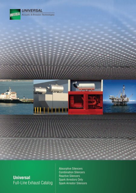
<strong>Universal</strong><br />
Full-Line Exhaust Catalog<br />
Absorptive <strong>Silencers</strong><br />
Combination <strong>Silencers</strong><br />
Reactive <strong>Silencers</strong><br />
Spark Arrestors Only<br />
Spark Arrestor <strong>Silencers</strong>
Table<br />
of Contents<br />
3 4 5 6 7<br />
2<br />
Table of Contents<br />
Full-Line Exhaust Catalog<br />
General Information 1.1<br />
Absorptive <strong>Silencers</strong> 2.1<br />
ADS Series<br />
1<br />
Combination <strong>Silencers</strong> 3.1<br />
BSE Series<br />
DSA and DDA Series<br />
Reactive <strong>Silencers</strong> 4.1<br />
OPS Series<br />
Spark Arrestors Only 5.1<br />
SPA Series<br />
See back cover for ordering information | www.universalAET.com<br />
Spark Arrestor <strong>Silencers</strong> 6.1<br />
OPA Series<br />
BSA Series<br />
EES Series<br />
Other Information 7.1<br />
BS10 Type D Flange Dimensions<br />
BS10 Type A Flange Dimensions<br />
DIN Flange Dimensions<br />
Plain Welded Flanges<br />
JIS Flange Dimensions<br />
ANSI B16.5 150# Flange Dimensions<br />
Steel Pipe Dimensions<br />
Wire Gauge Conversion Chart<br />
Note<br />
All dimensions in mm and weights<br />
in Kg, unless otherwise indicated.
1.1<br />
General<br />
Information<br />
General<br />
Information<br />
Company Profile<br />
Innovation, design and manufacturing<br />
expertise provide the solid foundation of our<br />
reputation in the specialist field of exhaust,<br />
emission and filtration systems at <strong>Universal</strong>,<br />
formerly <strong>Universal</strong> Silencer and<br />
Nelson-Burgess.<br />
For more than 50 years our name has been<br />
synonymous with quality and innovation of<br />
design achieved through partnerships with<br />
our customers.<br />
Our product range of industrial and marine<br />
silencers, mufflers and filtration products<br />
have been internationally recognized for<br />
offering the highest standard of quality,<br />
reliability, and performance. Our insight and<br />
expertise justify our reputation as the leader<br />
in exhaust and filtration systems.<br />
We take pride in providing a total value<br />
package of the most technologically<br />
advanced products and innovative services<br />
in the industry. Working hand in hand with<br />
our customers, we tailor solutions to specific<br />
applications.<br />
In this rapidly changing world, our advanced<br />
design and development testing facilities will<br />
help our customers meet the environmental<br />
challenges of the 21st century and beyond.<br />
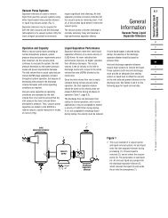
Silencer Sizing<br />
You must know the following information:<br />
A exhaust flow rate (m 3 /sec)<br />
B silencer inlet size (mm 2 )<br />
C level of silencing required<br />
Calculate exhaust gas velocity by dividing<br />
the flow rate by the pipe area:<br />
Reference the pressure drop curve in the<br />
silencer spec sheets. Using the calculated<br />
exhaust gas velocity, find the corresponding<br />
estimated pressure drop on the curve. If you<br />
have selected a silencer that achieves your<br />
silencing level requirements at an acceptable<br />
pressure drop level, you have identified the<br />
silencer that is right for you!<br />
Selection Assistance<br />
If you need help with selecting and sizing<br />
your silencer, please contact your nearest<br />
<strong>Universal</strong> commercial office (see back cover of<br />
<strong>catalog</strong>). Please also visit our interactive sizing<br />
application software on our website:<br />
www.universalaet.com. The software also<br />
has some current engine manufacturer<br />
performance data from which to select.<br />
Dimensional drawings for most silencers are<br />
also available for download on the website.<br />
Notes<br />
exhaust flow rate (m 3 /sec)<br />
silencer inlet pipe area (m 2 )<br />
Keep in mind that silencers are not designed<br />
to support their weight from the inlet or outlet<br />
tube, or support other components of the<br />
exhaust system, such as stacks. For the most<br />
efficient operation of all silencing units, proper<br />
mounting attachments are required. Domed<br />
heads or flat plates with gussets vary by model<br />
and size.<br />
1 2 3 4 5 6 7<br />
See back cover for ordering information | www.universalaet.com
2.1<br />
ADS Series<br />
Absorptive<br />
<strong>Silencers</strong><br />
<strong>Universal</strong>’s ADS silencers are recommended<br />
for the silencing of internal combustion<br />
engine exhaust and air vacuum<br />
discharges. They are available in two<br />
attenuation ratings:<br />
ADS 25 = 25 dB(A), ADS 35 = 35 dB(A).<br />
They utilise the original “straight through”<br />
absorptive principle, with exhaust pulse<br />
noise being effectively dissipated by<br />
absorptive material. This design provides<br />
very low restriction to exhaust gases, thus<br />
back pressure is negligible. <strong>Silencers</strong> of this<br />
type may also be used as secondary units on<br />
systems using reactive primary silencers.<br />
Pressure Drop mmWg<br />
Attenuation dB<br />
450<br />
400<br />
300°C<br />
350°C<br />
350<br />
400°C<br />
450°C<br />
300<br />
500°C<br />
550°C<br />
250<br />
200<br />
150<br />
100<br />
50<br />
0<br />
20 25 30 35 40 45 50 55 60 65 70<br />
Velocity m/sec<br />
50<br />
45<br />
40<br />
35<br />
30<br />
25<br />
20<br />
15<br />
10<br />
5<br />
0<br />
31.5 63 125 250 500 1000 2000 4000 8000<br />
Octave Band Centre Frequency<br />
Actual performance data may vary.<br />
ADS 35<br />
ADS 25<br />
ADS25<br />
Attenuation Level 25 dB(A) 35 dB(A)<br />
Absorptive <strong>Silencers</strong><br />
ADS35<br />
Orientation Horizontal or vertical Horizontal or vertical<br />
Standard Flange 90 mm–500 mm bore = BS 10 90 mm–500 mm bore = BS 10<br />
Optional Flanges ANSI, JIS, DIN and others ANSI, JIS, DIN and others<br />
Pipe Threads<br />
25 mm–75 mm bore - BSP<br />
external threaded<br />
25 mm–75 mm bore - BSP<br />
external threaded<br />
Finish Heat resistant paint Heat resistant paint<br />
Optional Finishes<br />
Standard Material<br />
Optional Material<br />
Optional Assemblies<br />
Shot Blast Metal Spray to<br />
BS 2569 Part 2 Class D (1965)<br />
plus two coats of silicon seal<br />
BSEN 10025 S275 or equivalent<br />
to 3 mm and above<br />
• Cor-Ten<br />
• Boiler Plate P265GH<br />
• Aluminised Steel<br />
• Stainless Steel Grades 304L,<br />
316 and 409<br />
• Rain cap<br />
• Elbows<br />
• Tailpipes<br />
• Lagging and Cladding<br />
• Mating flange assemblies<br />
• Lifting lugs<br />
• Support feet (horizontal and<br />
vertical)<br />
• Inspection doors<br />
• Explosion relief doors<br />
1 2 3 4 5 6 7<br />
See back cover for ordering information | www.universalAET.com<br />
“BS10” Mounting Flange:<br />
Bore sizes 3.5" (90) and above.<br />
“B” Male Pipe Threads:<br />
BSP end offered in sizes 3" (75)<br />
and smaller.<br />
All information correct at time of printing. <strong>Universal</strong> has a policy of continuous<br />
improvement. Therefore we reserve the right to change the specifications of these<br />
silencers without notice.
2.2<br />
Absorptive<br />
<strong>Silencers</strong><br />
ADS 25 Series<br />
1 2 3 4 5 6 7<br />
Absorptive <strong>Silencers</strong><br />
End Entry, End Exit<br />
Side Entry, End Exit<br />
Part Number Configuration Bore Size A B C D K L Weight<br />
50-1A025-AA End Entry, End Exit 25 (1.0") 89 380 20 -- -- 1.6<br />
50-1A038-AA End Entry, End Exit 38 (1.5") 115 610 30 -- -- 2.7<br />
50-1A050-AA End Entry, End Exit 50 (2.0") 115 765 35 -- -- 3<br />
50-1A065-AA End Entry, End Exit 65 (2.5") 133 765 45 -- -- 4.6<br />
50-1A075-AA End Entry, End Exit 75 (3.0") 152 765 50 -- -- 6.2<br />
50-3A090-AA Side Entry, End Exit 90 (3.5") 259 740 50 690 180 16.4<br />
50-1A090-AA End Entry, End Exit 90 (3.5") 259 740 50 -- -- 16.4<br />
50-3A100-AA Side Entry, End Exit 100 (4.0") 259 800 50 745 180 23<br />
50-1A100-AA End Entry, End Exit 100 (4.0") 259 800 50 -- -- 23<br />
50-3A125-AA Side Entry, End Exit 125 (5.0") 303 950 50 890 205 32<br />
50-1A125-AA End Entry, End Exit 125 (5.0") 303 950 50 -- -- 32<br />
50-3A150-AA Side Entry, End Exit 150 (6.0") 356 1100 75 1050 255 44<br />
50-1A150-AA End Entry, End Exit 150 (6.0") 356 1100 75 -- -- 44<br />
50-3A175-AA Side Entry, End Exit 175 (7.0") 356 1250 75 1185 255 49<br />
50-1A175-AA End Entry, End Exit 175 (7.0") 356 1250 75 -- -- 49<br />
50-3A200-AA Side Entry, End Exit 200 (8.0") 412 1400 75 1310 285 64<br />
50-1A200-AA End Entry, End Exit 200 (8.0") 412 1400 75 -- -- 64<br />
50-3A225-AA Side Entry, End Exit 225 (9.0") 451 1550 75 1450 305 67<br />
50-1A225-AA End Entry, End Exit 225 (9.0") 451 1550 75 -- -- 67<br />
50-3A250-AA Side Entry, End Exit 250 (10.0") 565 1700 75 1525 360 131<br />
50-1A250-AA End Entry, End Exit 250 (10.0") 565 1700 75 -- -- 131<br />
50-3A300-AA Side Entry, End Exit 300 (12.0") 565 2000 100 1825 385 155<br />
50-1A300-AA End Entry, End Exit 300 (12.0") 565 2000 100 -- -- 155<br />
50-3A350-AA Side Entry, End Exit 350 (14.0") 667 2300 100 2085 435 221<br />
50-1A350-AA End Entry, End Exit 350 (14.0") 667 2300 100 -- -- 221<br />
50-3A400-AA Side Entry, End Exit 400 (16.0") 690 2600 100 2395 445 251<br />
50-1A400-AA End Entry, End Exit 400 (16.0") 690 2600 100 -- -- 251<br />
50-3A450-AA Side Entry, End Exit 450 (18.0") 790 2900 100 2655 495 384<br />
50-1A450-AA End Entry, End Exit 450 (18.0") 790 2900 100 -- -- 384<br />
50-3A500-AA Side Entry, End Exit 500 (20.0") 840 3200 100 2920 520 451<br />
50-1A500-AA End Entry, End Exit 500 (20.0") 840 3200 100 -- -- 451<br />
All dimensions are in mm unless otherwise stated. All weights are in Kg and are approximate.<br />
Typical tolerances (mm): up to 300 ± 3; 300–900 ± 5; 900–3000 ± 9; over 3000 ± 12<br />
All information correct at time of printing. <strong>Universal</strong> has a policy of continuous<br />
improvement. Therefore we reserve the right to change the specifications of these<br />
silencers without notice.
2.3<br />
ADS 35 Series<br />
Absorptive<br />
<strong>Silencers</strong><br />
Absorptive <strong>Silencers</strong><br />
1 2 3 4 5 6 7<br />
End Entry, End Exit<br />
Side Entry, End Exit<br />
Part Number Configuration Bore Size A B C D K L Weight<br />
50-3Q090-AA Side Entry, End Exit 90 (3.5") 259 920 50 870 180 19.5<br />
50-1Q090-AA End Entry, End Exit 90 (3.5") 259 920 50 -- -- 19.5<br />
50-3Q100-AA Side Entry, End Exit 100 (4.0") 259 1000 50 945 180 26.5<br />
50-1Q100-AA End Entry, End Exit 100 (4.0") 259 1000 50 -- -- 26.5<br />
50-3Q125-AA Side Entry, End Exit 125 (5.0") 303 1200 50 1140 205 37.4<br />
50-1Q125-AA End Entry, End Exit 125 (5.0") 303 1200 50 -- -- 37.4<br />
50-3Q150-AA Side Entry, End Exit 150 (6.0") 356 1400 75 1350 255 52<br />
50-1Q150-AA End Entry, End Exit 150 (6.0") 356 1400 75 -- -- 52<br />
50-3Q175-AA Side Entry, End Exit 175 (7.0") 356 1600 75 1535 255 58<br />
50-1Q175-AA End Entry, End Exit 175 (7.0") 356 1600 75 -- -- 58<br />
50-3Q200-AA Side Entry, End Exit 200 (8.0") 412 1800 75 1710 285 80<br />
50-1Q200-AA End Entry, End Exit 200 (8.0") 412 1800 75 -- -- 80<br />
50-3Q225-AA Side Entry, End Exit 225 (9.0") 451 2000 75 1900 305 86.5<br />
50-1Q225-AA End Entry, End Exit 225 (9.0") 451 2000 75 -- -- 86.5<br />
50-3Q250-AA Side Entry, End Exit 250 (10.0") 565 2200 75 2025 360 157<br />
50-1Q250-AA End Entry, End Exit 250 (10.0") 565 2200 75 -- -- 157<br />
50-3Q300-AA Side Entry, End Exit 300 (12.0") 565 2600 100 2425 385 187<br />
50-1Q300-AA End Entry, End Exit 300 (12.0") 565 2600 100 -- -- 187<br />
50-3Q350-AA Side Entry, End Exit 350 (14.0") 667 3000 100 2785 435 267<br />
50-1Q350-AA End Entry, End Exit 350 (14.0") 667 3000 100 -- -- 267<br />
50-3Q400-AA Side Entry, End Exit 400 (16.0") 690 3400 100 3195 445 315<br />
50-1Q400-AA End Entry, End Exit 400 (16.0") 690 3400 100 -- -- 315<br />
50-3Q450-AA Side Entry, End Exit 450 (18.0") 790 3800 100 3555 495 489<br />
50-1Q450-AA End Entry, End Exit 450 (18.0") 790 3800 100 -- -- 489<br />
50-3Q500-AA Side Entry, End Exit 500 (20.0") 840 4200 100 3920 520 575<br />
50-1Q500-AA End Entry, End Exit 500 (20.0") 840 4200 100 -- -- 575<br />
See back cover for ordering information | www.universalAET.com<br />
All dimensions are in mm unless otherwise stated. All weights are in Kg and are approximate.<br />
Typical tolerances (mm): up to 300 ± 3; 300–900 ± 5; 900–3000 ± 9; over 3000 ± 12<br />
All information correct at time of printing. <strong>Universal</strong> has a policy of continuous<br />
improvement. Therefore we reserve the right to change the specifications of these<br />
silencers without notice.
3.1<br />
BSE Series<br />
Combination<br />
<strong>Silencers</strong><br />
<strong>Universal</strong> recommends the BSE silencer for<br />
optimum silencing applications. The unit is<br />
designed with a reactive chamber and an<br />
absorptive chamber to treat low and high<br />
frequencies. The BSE range is available in<br />
three attenuation ratings: BSE 25 = 25 dB(A),<br />
BSE 35 = 35 dB(A) and BSE 45 =<br />
45 dB(A).<br />
Pressure Drop mmWg<br />
Attenuation dB<br />
400<br />
300°C<br />
400<br />
350°C<br />
400°C<br />
350<br />
450°C<br />
500°C<br />
300<br />
550°C<br />
250<br />
200<br />
150<br />
100<br />
50<br />
0<br />
20 25 30 35 40 45 50 55 60 65 70<br />
Velocity m/sec<br />
50<br />
45<br />
40<br />
35<br />
30<br />
25<br />
20<br />
15<br />
10<br />
5<br />
0<br />
31.5 63 125 250 500 1000 2000 4000 8000<br />
Octave Band Centre Frequency<br />
Actual performance data may vary.<br />
“BS10” Mounting Flange:<br />
Bore sizes 10" (250 mm) and above<br />
BSE 45<br />
BSE 35<br />
BSE 25<br />
Attenuation<br />
Level<br />
Combination <strong>Silencers</strong><br />
BSE 25 BSE 35 BSE 45<br />
25 dB(A) 35 dB(A) 45 dB(A)<br />
Orientation Horizontal or vertical Horizontal or vertical Horizontal or vertical<br />
Standard Flange<br />
Optional<br />
Flanges<br />
250 mm–750 mm<br />
bore = BS 10<br />
250 mm–750 mm<br />
bore = BS 10<br />
ANSI, JIS, DIN and others ANSI, JIS, DIN and others<br />
250 mm–750 mm<br />
bore = BS 10<br />
ANSI, JIS, DIN and others<br />
Pipe Threads Not applicable Not applicable Not applicable<br />
Finish Heat resistant paint Heat resistant paint Heat resistant paint<br />
Optional<br />
Finishes<br />
Standard<br />
Material<br />
Optional<br />
Material<br />
Optional<br />
Assemblies<br />
Shot Blast Metal Spray to<br />
BS 2569 Part 2 Class D<br />
(1965) plus two coats of<br />
silicon seal<br />
BSEN 10025 S275<br />
or equivalent, 3 mm<br />
and above<br />
• Cor-Ten<br />
• Boiler Plate P265GH<br />
• Aluminised Steel<br />
• Stainless Steel Grades<br />
304L, 316 and 409<br />
• Rain cap<br />
• Elbows<br />
• Tailpipes<br />
• Lagging and cladding<br />
Shot Blast Metal Spray to<br />
BS 2569 Part 2 Class D<br />
(1965) plus two coats of<br />
silicon seal<br />
BSEN 10025 S275<br />
or equivalent, 3 mm<br />
and above<br />
• Cor-Ten<br />
• Boiler Plate P265GH<br />
• Aluminised Steel<br />
• Stainless Steel Grades<br />
304L, 316 and 409<br />
Shot Blast Metal Spray to<br />
BS 2569 Part 2 Class D<br />
(1965) plus two coats of<br />
silicon seal<br />
BSEN 10025 S275<br />
or equivalent, 3 mm<br />
and above<br />
• Cor-Ten<br />
• Boiler Plate P265GH<br />
• Aluminised Steel<br />
• Stainless Steel Grades<br />
304L, 316 and 409<br />
• Mating flange assemblies • Mating flange assemblies • Mating flange assemblies<br />
• Lifting lugs<br />
• Support feet (horizontal<br />
and vertical)<br />
• Inspection doors<br />
• Explosion relief doors<br />
• Rain cap<br />
• Elbows<br />
• Tailpipes<br />
• Lagging and cladding<br />
• Lifting lugs<br />
• Support feet (horizontal<br />
and vertical)<br />
• Inspection doors<br />
• Explosion relief doors<br />
• Rain cap<br />
• Elbows<br />
• Tailpipes<br />
• Lagging and cladding<br />
• Lifting lugs<br />
• Support feet (horizontal<br />
and vertical)<br />
• Inspection doors<br />
• Explosion relief doors<br />
1 2 3 4 5 6 7<br />
See back cover for ordering information | www.universalAET.com<br />
All information correct at time of printing. <strong>Universal</strong> has a policy of continuous<br />
improvement. Therefore we reserve the right to change the specifications of these<br />
silencers without notice.
3.2<br />
Combination<br />
<strong>Silencers</strong><br />
BSE 25 Series<br />
1 2 3 4 5 6 7<br />
Combination <strong>Silencers</strong><br />
End Entry, End Exit<br />
Side Entry, End Exit<br />
Part Number Configuration Bore Size A B C D K max K min L Weight<br />
50-3H250-AA Side Entry, End Exit 250 (10.0") 667 1500 75 1315 1315 410 159<br />
50-1H250-AA End Entry, End Exit 250 (10.0") 667 1500 75 -- -- -- 159<br />
50-3H300-AA Side Entry, End Exit 300 (12.0") 740 1800 100 1660 1290 470 258<br />
50-1H300-AA End Entry, End Exit 300 (12.0") 740 1800 100 -- -- -- 258<br />
50-3H350-AA Side Entry, End Exit 350 (14.0") 840 2100 100 1925 1470 520 343<br />
50-1H350-AA End Entry, End Exit 350 (14.0") 840 2100 100 -- -- -- 343<br />
50-3H400-AA Side Entry, End Exit 400 (16.0") 890 2400 100 2200 1655 545 408<br />
50-1H400-AA End Entry, End Exit 400 (16.0") 890 2400 100 -- -- -- 408<br />
50-3H450-AA Side Entry, End Exit 450 (18.0") 990 2700 100 2465 1845 595 520<br />
50-1H450-AA End Entry, End Exit 450 (18.0") 990 2700 100 -- -- -- 520<br />
50-3H500-AA Side Entry, End Exit 500 (20.0") 1090 3000 100 2735 2030 645 742<br />
50-1H500-AA End Entry, End Exit 500 (20.0") 1090 3000 100 -- -- -- 742<br />
50-3H550-AA Side Entry, End Exit 550 (22.0") 1190 3300 100 3005 2220 695 905<br />
50-1H550-AA End Entry, End Exit 550 (22.0") 1190 3300 100 -- -- -- 905<br />
50-3H600-AA Side Entry, End Exit 600 (24.0") 1290 3600 100 3275 2405 745 1076<br />
50-1H600-AA End Entry, End Exit 600 (24.0") 1290 3600 100 -- -- -- 1076<br />
50-3H650-AA Side Entry, End Exit 650 (26.0") 1390 3500 100 3165 2195 795 1278<br />
50-1H650-AA End Entry, End Exit 650 (26.0") 1390 3500 100 -- -- -- 1278<br />
50-3H700-AA Side Entry, End Exit 700 (28.0") 1485 3800 100 3455 2385 845 1460<br />
50-1H700-AA End Entry, End Exit 700 (28.0") 1485 3800 100 -- -- -- 1460<br />
50-3H750-AA Side Entry, End Exit 750 (30.0") 1585 4000 150 3665 2525 945 1770<br />
50-1H750-AA End Entry, End Exit 750 (30.0") 1585 4000 150 -- -- -- 1770<br />
All dimensions are in mm unless otherwise stated. All weights are in Kg and are approximate.<br />
Typical tolerances (mm): up to 300 ± 3; 300–900 ± 5; 900–3000 ± 9; over 3000 ± 12<br />
All information correct at time of printing. <strong>Universal</strong> has a policy of continuous<br />
improvement. Therefore we reserve the right to change the specifications of these<br />
silencers without notice.
3.3<br />
BSE 35 Series<br />
Combination <strong>Silencers</strong><br />
Combination<br />
<strong>Silencers</strong><br />
1 2 3 4 5 6 7<br />
End Entry, End Exit<br />
Side Entry, End Exit<br />
Part Number Configuration Bore Size A B C D K max K min L Weight<br />
50-3G250-AA Side Entry, End Exit 250 (10.0") 667 2000 75 1815 1815 410 189<br />
50-1G250-AA End Entry, End Exit 250 (10.0") 667 2000 75 -- -- -- 189<br />
50-3G300-AA Side Entry, End Exit 300 (12.0") 740 2400 100 2260 1890 470 312<br />
50-1G300-AA End Entry, End Exit 300 (12.0") 740 2400 100 -- -- -- 312<br />
50-3G350-AA Side Entry, End Exit 350 (14.0") 840 2800 100 2625 2170 520 414<br />
50-1G350-AA End Entry, End Exit 350 (14.0") 840 2800 100 -- -- -- 414<br />
50-3G400-AA Side Entry, End Exit 400 (16.0") 890 3200 100 3000 2455 545 512<br />
50-1G400-AA End Entry, End Exit 400 (16.0") 890 3200 100 -- -- -- 512<br />
50-3G450-AA Side Entry, End Exit 450 (18.0") 990 3600 100 3365 2745 595 654<br />
50-1G450-AA End Entry, End Exit 450 (18.0") 990 3600 100 -- -- -- 654<br />
50-3G500-AA Side Entry, End Exit 500 (20.0") 1090 4000 100 3735 3030 645 941<br />
50-1G500-AA End Entry, End Exit 500 (20.0") 1090 4000 100 -- -- -- 941<br />
50-3G550-AA Side Entry, End Exit 550 (22.0") 1190 4400 100 4105 3320 695 1145<br />
50-1G550-AA End Entry, End Exit 550 (22.0") 1190 4400 100 -- -- -- 1145<br />
50-3G600-AA Side Entry, End Exit 600 (24.0") 1290 4800 100 4475 3605 745 1365<br />
50-1G600-AA End Entry, End Exit 600 (24.0") 1290 4800 100 -- -- -- 1365<br />
50-3G650-AA Side Entry, End Exit 650 (26.0") 1390 4450 100 4115 3145 795 1595<br />
50-1G650-AA End Entry, End Exit 650 (26.0") 1390 4450 100 -- -- -- 1595<br />
50-3G700-AA Side Entry, End Exit 700 (28.0") 1485 4850 100 4505 3435 845 1853<br />
50-1G700-AA End Entry, End Exit 700 (28.0") 1485 4850 100 -- -- -- 1853<br />
50-3G750-AA Side Entry, End Exit 750 (30.0") 1585 5100 150 4765 3625 945 2220<br />
50-1G750-AA End Entry, End Exit 750 (30.0") 1585 5100 150 -- -- -- 2220<br />
See back cover for ordering information | www.universalAET.com<br />
All dimensions are in mm unless otherwise stated. All weights are in Kg and are approximate.<br />
Typical tolerances (mm): up to 300 ± 3; 300–900 ± 5; 900–3000 ± 9, over 3000 ± 12<br />
All information correct at time of printing. <strong>Universal</strong> has a policy of continuous<br />
improvement. Therefore we reserve the right to change the specifications of these<br />
silencers without notice.
3.4<br />
Combination<br />
<strong>Silencers</strong><br />
BSE 45 Series<br />
1 2 3 4 5 6 7<br />
Combination <strong>Silencers</strong><br />
End Entry, End Exit<br />
Side Entry, End Exit<br />
Part Number Configuration Bore Size A B C D K max K min L Weight<br />
50-3F250-AA Side Entry, End Exit 250 (10.0") 667 2650 75 2465 2465 410 242<br />
50-1F250-AA End Entry, End Exit 250 (10.0") 667 2650 75 -- -- -- 242<br />
50-3F300-AA Side Entry, End Exit 300 (12.0") 740 3150 100 3010 2640 470 395<br />
50-1F300-AA End Entry, End Exit 300 (12.0") 740 3150 100 -- -- -- 395<br />
50-3F350-AA Side Entry, End Exit 350 (14.0") 840 3700 100 3525 3070 520 531<br />
50-1F350-AA End Entry, End Exit 350 (14.0") 840 3700 100 -- -- -- 531<br />
50-3F400-AA Side Entry, End Exit 400 (16.0") 890 4200 100 4000 3455 545 635<br />
50-1F400-AA End Entry, End Exit 400 (16.0") 890 4200 100 -- -- -- 635<br />
50-3F450-AA Side Entry, End Exit 450 (18.0") 990 4750 100 4515 3895 595 816<br />
50-1F450-AA End Entry, End Exit 450 (18.0") 990 4750 100 -- -- -- 816<br />
50-3F500-AA Side Entry, End Exit 500 (20.0") 1090 5250 100 4985 4280 645 1203<br />
50-1F500-AA End Entry, End Exit 500 (20.0") 1090 5250 100 -- -- -- 1203<br />
50-3F550-AA Side Entry, End Exit 550 (22.0") 1190 5800 100 5505 4720 695 1475<br />
50-1F550-AA End Entry, End Exit 550 (22.0") 1190 5800 100 -- -- -- 1475<br />
50-3F600-AA Side Entry, End Exit 600 (24.0") 1290 6300 100 5975 5105 745 1759<br />
50-1F600-AA End Entry, End Exit 600 (24.0") 1290 6300 100 -- -- -- 1759<br />
50-3F650-AA Side Entry, End Exit 650 (26.0") 1390 5600 100 5265 4295 795 1994<br />
50-1F650-AA End Entry, End Exit 650 (26.0") 1390 5600 100 -- -- -- 1994<br />
50-3F700-AA Side Entry, End Exit 700 (28.0") 1485 6150 100 5805 4735 845 2339<br />
50-1F700-AA End Entry, End Exit 700 (28.0") 1485 6150 100 -- -- -- 2339<br />
50-3F750-AA Side Entry, End Exit 750 (30.0") 1585 6500 150 6165 5025 945 2803<br />
50-1F750-AA End Entry, End Exit 750 (30.0") 1585 6500 150 -- -- -- 2803<br />
All dimensions are in mm unless otherwise stated. All weights are in Kg and are approximate.<br />
Typical tolerances (mm): up to 300 ± 3; 300–900 ± 5; 900–3000 ± 9; over 3000 ± 12<br />
All information correct at time of printing. <strong>Universal</strong> has a policy of continuous<br />
improvement. Therefore we reserve the right to change the specifications of these<br />
silencers without notice.
3.5<br />
DSA and DDA Series<br />
Combination<br />
<strong>Silencers</strong><br />
<strong>Universal</strong>’s DSA and DDA silencers are<br />
recommended for small and medium sized<br />
diesel and petrol engines. They employ a<br />
twin or triple chamber design where an initial<br />
low restriction expansion and diffusion of<br />
the exhaust gases takes place in a primary<br />
reactive chamber. Attenuation of the higher<br />
frequencies is obtained in the secondary<br />
absorptive section. The DSA provides<br />
25 dB(A) attenuation and the DDA<br />
provides 30 dB(A) attenuation.<br />
Pressure Drop mmWg<br />
Attenuation dB<br />
450<br />
400<br />
300°C<br />
350°C<br />
350<br />
400°C<br />
450°C<br />
300<br />
500°C<br />
550°C<br />
250<br />
200<br />
150<br />
100<br />
50<br />
0<br />
20 25 30 35 40 45 50 55 60 65 70<br />
Velocity m/sec<br />
45<br />
40<br />
35<br />
30<br />
25<br />
20<br />
15<br />
10<br />
5<br />
0<br />
31.5 63 125 250 500 1000 2000 4000 8000<br />
Octave Band Centre Frequency<br />
Actual performance data may vary.<br />
DDA<br />
DSA<br />
DSA<br />
Attenuation Level 25 dB(A) 30 dB(A)<br />
Combination <strong>Silencers</strong><br />
DDA<br />
Orientation Horizontal or vertical Horizontal or vertical<br />
Standard Flange 90 mm–300 mm bore = BS 10 90 mm–300 mm bore = BS 10<br />
Optional Flanges ANSI, JIS, DIN and others ANSI, JIS, DIN and others<br />
Pipe Threads<br />
25 mm–75 mm bore = BSP<br />
external threaded<br />
25 mm–75 mm bore = BSP<br />
external threaded<br />
Finish Heat resistant paint Heat resistant paint<br />
Optional Finishes<br />
Standard Material<br />
Optional Material<br />
Optional Assemblies<br />
Shot Blast Metal Spray to<br />
BS 2569 Part 2 Class D (1965)<br />
plus two coats of silicon seal<br />
BSEN 10025 S275 or equivalent,<br />
3 mm and above<br />
• Cor-Ten<br />
• Boiler Plate P265GH<br />
• Aluminised Steel<br />
• Stainless Steel Grades 304L,<br />
316 and 409<br />
• Rain cap<br />
• Elbows<br />
• Tailpipes<br />
• Lagging and Cladding<br />
• Mating flange assemblies<br />
• Lifting lugs<br />
• Support feet (horizontal<br />
and vertical)<br />
• Inspection doors<br />
• Explosion relief doors<br />
Shot Blast Metal Spray to<br />
BS 2569 Part 2 Class D (1965)<br />
plus two coats of silicon seal<br />
BSEN 10025 S275 or equivalent,<br />
3 mm and above<br />
• Cor-Ten<br />
• Boiler Plate P265GH<br />
• Aluminised Steel<br />
• Stainless Steel Grades 304L,<br />
316 and 409<br />
• Rain cap<br />
• Elbows<br />
• Tailpipes<br />
• Lagging and Cladding<br />
• Mating flange assemblies<br />
• Lifting lugs<br />
• Support feet (horizontal and<br />
vertical)<br />
• Inspection doors<br />
• Explosion relief doors<br />
1 2 3 4 5 6 7<br />
See back cover for ordering information | www.universalAET.com<br />
“BS10” Mounting Flange:<br />
Bore sizes 3.5" (90) and above.<br />
“B” Male Pipe Threads:<br />
BSP end offered in sizes 3" (75)<br />
and smaller.<br />
All information correct at time of printing. <strong>Universal</strong> has a policy of continuous<br />
improvement. Therefore we reserve the right to change the specifications of these<br />
silencers without notice.
3.6<br />
Combination<br />
<strong>Silencers</strong><br />
DSA Series<br />
1 2 3 4 5 6 7<br />
Combination <strong>Silencers</strong><br />
End Entry, End Exit<br />
Part Number Configuration Bore Size A B C D E F G Weight<br />
50-1C025-AA End Entry, End Exit 25 (1") 89 255 45 7 13 15 1<br />
50-1C038-AA End Entry, End Exit 38 (1.5") 115 380 50 12 21 24 3<br />
50-1C050-AA End Entry, End Exit 50 (2") 152 510 60 14 27 30 5<br />
50-1C065-AA End Entry, End Exit 65 (2.5") 178 610 65 19 33 38 7<br />
50-1C075-AA End Entry, End Exit 75 (3") 206 735 75 22 40 46 12<br />
50-1C090-AA End Entry, End Exit 90 (3.5") 259 735 75 25 45 51 21<br />
50-1C100-AA End Entry, End Exit 100 (4") 285 890 75 30 52 60 28<br />
50-1C125-AA End Entry, End Exit 125 (5") 356 890 75 37 65 75 33<br />
50-1C150-AA End Entry, End Exit 150 (6") 412 1015 75 45 78 90 55<br />
50-1C175-AA End Entry, End Exit 175 (7") 452 1180 75 51 89 102 60<br />
50-1C200-AA End Entry, End Exit 200 (8") 520 1350 75 60 104 115 75<br />
50-1C250-AA End Entry, End Exit 250 (10") 620 1750 75 73 125 145 170<br />
50-1C300-AA End Entry, End Exit 300 (12") 730 2220 100 87 147 175 228<br />
All dimensions are in mm unless otherwise stated. All weights are in Kg and are approximate.<br />
Typical tolerances (mm): up to 300 ± 3; 300–900 ± 5; 900–3000 ± 9<br />
All information correct at time of printing. <strong>Universal</strong> has a policy of continuous<br />
improvement. Therefore we reserve the right to change the specifications of these<br />
silencers without notice.
3.7<br />
DDA Series<br />
Combination <strong>Silencers</strong><br />
Combination<br />
<strong>Silencers</strong><br />
1 2 3 4 5 6 7<br />
Side Entry, End Exit<br />
End Entry, End Exit<br />
Part Number Configuration Bore Size A B C D E F G K L Weight<br />
50-1B025-AA End Entry, End Exit 25 (1") 89 380 16 7 13 15 -- -- 2<br />
50-1B038-AA End Entry, End Exit 38 (1.5") 115 560 30 12 21 24 -- -- 4<br />
50-1B050-AA End Entry, End Exit 50 (2") 152 765 35 14 27 30 -- -- 8<br />
50-1B065-AA End Entry, End Exit 65 (2.5") 178 889 38 19 33 38 -- -- 12<br />
50-1B075-AA End Entry, End Exit 75 (3") 206 1015 48 22 40 46 -- -- 15<br />
50-3B090-AA Side Entry, End Exit 90 (3.5") 259 1015 75 25 45 51 1015 205 27<br />
50-1B090-AA End Entry, End Exit 90 (3.5") 259 1015 75 25 45 51 -- -- 27<br />
50-3B100-AA Side Entry, End Exit 100 (4") 285 1220 75 30 52 60 1155 215 37<br />
50-1B100-AA End Entry, End Exit 100 (4") 285 1220 75 30 52 60 -- -- 37<br />
50-3B125-AA Side Entry, End Exit 125 (5") 356 1220 75 37 65 75 1145 255 50<br />
50-1B125-AA End Entry, End Exit 126 (5") 356 1220 75 37 65 75 -- -- 50<br />
50-3B150-AA Side Entry, End Exit 150 (6") 412 1500 75 45 78 90 1395 280 70<br />
50-1B150-AA End Entry, End Exit 150 (6") 412 1500 75 45 78 90 -- -- 70<br />
50-3B175-AA Side Entry, End Exit 175 (7") 452 1600 75 51 89 102 1485 305 80<br />
50-1B175-AA End Entry, End Exit 175 (7") 452 1600 75 51 89 102 -- -- 80<br />
50-3B200-AA Side Entry, End Exit 200 (8") 520 1810 75 60 104 115 1680 335 100<br />
50-1B200-AA End Entry, End Exit 200 (8") 520 1810 75 60 104 115 -- -- 100<br />
50-3B250-AA Side Entry, End Exit 250 (10") 620 2360 75 73 125 145 2205 385 230<br />
50-1B250-AA End Entry, End Exit 250 (10") 620 2360 75 73 125 145 -- -- 230<br />
50-3B300-AA Side Entry, End Exit 300 (12") 730 2800 100 87 147 175 2610 470 305<br />
50-1B300-AA End Entry, End Exit 300 (12") 730 2800 100 87 147 175 -- -- 305<br />
See back cover for ordering information | www.universalAET.com<br />
All dimensions are in mm unless otherwise stated. All weights are in Kg and are approximate.<br />
Typical tolerances (mm): up to 300 ± 3; 300–900 ± 5; 900–3000 ± 9<br />
All information correct at time of printing. <strong>Universal</strong> has a policy of continuous<br />
improvement. Therefore we reserve the right to change the specifications of these<br />
silencers without notice.
4.1<br />
OPS Series<br />
Reactive<br />
<strong>Silencers</strong><br />
Pressure Drop mmWg<br />
Attenuation dB<br />
<strong>Universal</strong>’s OPS reactive silencers are<br />
recommended for industrial and marine<br />
applications where low frequency noise<br />
dominates. The design consists of a series of<br />
expansion chambers having interconnecting<br />
tubes. The OPS range is available in two<br />
attenuation ratings: OPS 25 = 25 dB(A) and<br />
OPS 30 = 30 dB(A).<br />
<strong>Universal</strong> OPS range of silencers can be<br />
used in conjunction with other <strong>Universal</strong><br />
silencers to produce the optimum<br />
acoustic system.<br />
1000<br />
250°C<br />
900<br />
300°C<br />
800<br />
350°C<br />
400°C<br />
700<br />
450°C<br />
500°C<br />
600<br />
500<br />
400<br />
300<br />
200<br />
100<br />
0<br />
20 25 30 35 40 45 50 55 60 65 70 75<br />
35<br />
30<br />
25<br />
20<br />
15<br />
10<br />
5<br />
Reactive OPS<br />
0<br />
31.5 63 125 250 500 1000 2000 4000 8000<br />
OPS 30<br />
OPS 25<br />
Reactive <strong>Silencers</strong><br />
OPS 25 OPS 30<br />
Attenuation Level 25 dB(A) 30 dB(A)<br />
Orientation Horizontal or vertical Horizontal or vertical<br />
Standard Flange 90 mm–950 mm bore = BS 10 90 mm–950 mm bore = BS 10<br />
Optional Flanges ANSI, JIS, DIN and others ANSI, JIS, DIN and others<br />
Pipe Threads Not applicable Not applicable<br />
Finish Heat resistant paint Heat resistant paint<br />
Optional Finishes<br />
Standard Material<br />
Optional Material<br />
Optional Assemblies<br />
Shot Blast Metal Spray to<br />
BS 2569 Part 2 Class D (1965)<br />
plus two coats of silicon seal<br />
BSEN 10025 S275 or equivalent,<br />
3 mm and above<br />
• Cor-Ten<br />
• Boiler Plate P265GH<br />
• Aluminised Steel<br />
• Stainless Steel Grades 304L,<br />
316 and 409<br />
• Rain cap<br />
• Elbows<br />
• Tailpipes<br />
• Lagging and Cladding<br />
• Mating flange assemblies<br />
• Lifting lugs<br />
• Support feet (horizontal<br />
and vertical)<br />
• Inspection doors<br />
• Explosion relief doors<br />
Shot Blast Metal Spray to<br />
BS 2569 Part 2 Class D (1965)<br />
plus two coats of silicon seal<br />
BSEN 10025 S275 or equivalent,<br />
3 mm and above<br />
• Cor-Ten<br />
• Boiler Plate P265GH<br />
• Aluminised Steel<br />
• Stainless Steel Grades 304L,<br />
316 and 409<br />
• Rain cap<br />
• Elbows<br />
• Tailpipes<br />
• Lagging and Cladding<br />
• Mating flange assemblies<br />
• Lifting lugs<br />
• Support feet (horizontal<br />
and vertical)<br />
• Inspection doors<br />
• Explosion relief doors<br />
1 2 3 4 5 6 7<br />
See back cover for ordering information | www.universalAET.com<br />
Octave Band Centre Frequency<br />
Actual performance data may vary.<br />
“BS10” Mounting Flange:<br />
Bore sizes 3.5" (90) and above.<br />
All information correct at time of printing. <strong>Universal</strong> has a policy of continuous<br />
improvement. Therefore we reserve the right to change the specifications of these<br />
silencers without notice.
4.2<br />
Reactive<br />
<strong>Silencers</strong><br />
OPS 25 Series<br />
1 2 3 4 5 6 7<br />
Reactive <strong>Silencers</strong><br />
End Entry, End Exit<br />
Side Entry, End Exit<br />
Part Number Configuration Bore Size A B C D K max K min L Weight<br />
50-3T090-AA Side Entry, End Exit 90 (3.5") 303 815 50 770 476 205 31<br />
50-1T090-AA End Entry, End Exit 90 (3.5") 303 815 50 -- -- 205 31<br />
50-3T100-AA Side Entry, End Exit 100 (4.0") 303 915 50 864 557 205 47<br />
50-1T100-AA End Entry, End Exit 100 (4.0") 303 915 50 -- -- 205 47<br />
50-3T125-AA Side Entry, End Exit 125 (5.0") 356 1015 75 975 635 230 63<br />
50-1T125-AA End Entry, End Exit 125 (5.0") 356 1015 75 -- -- 230 63<br />
50-3T150-AA Side Entry, End Exit 150 (6.0") 412 1170 75 1103 659 285 90<br />
50-1T150-AA End Entry, End Exit 150 (6.0") 412 1170 75 -- -- 285 90<br />
50-3T175-AA Side Entry, End Exit 175 (7.0") 451 1170 75 1070 607 305 136<br />
50-1T175-AA End Entry, End Exit 175 (7.0") 451 1170 75 -- -- 305 136<br />
50-3T200-AA Side Entry, End Exit 200 (8.0") 565 1320 75 1171 755 360 168<br />
50-1T200-AA End Entry, End Exit 200 (8.0") 565 1320 75 -- -- 360 168<br />
50-3T225-AA Side Entry, End Exit 225 (9.0") 565 1780 75 1631 1067 360 218<br />
50-1T225-AA End Entry, End Exit 225 (9.0") 565 1780 75 -- -- 360 218<br />
50-3T250-AA Side Entry, End Exit 250 (10.0") 667 2085 75 1933 1197 410 254<br />
50-1T250-AA End Entry, End Exit 250 (10.0") 667 2085 75 -- -- 410 254<br />
50-3T300-AA Side Entry, End Exit 300 (12.0") 740 2085 100 1885 1172 470 381<br />
50-1T300-AA End Entry, End Exit 300 (12.0") 740 2085 100 -- -- 470 381<br />
50-3T350-AA Side Entry, End Exit 350 (14.0") 840 2690 100 2440 1528 520 518<br />
50-1T350-AA End Entry, End Exit 350 (14.0") 840 2690 100 -- -- 520 518<br />
Continued on next page<br />
All dimensions are in mm unless otherwise stated. All weights are in Kg and are approximate.<br />
Typical tolerances (mm): up to 300 ± 3; 300–900 ± 5; 900–3000 ± 9; 3000–9000 ± 12<br />
All information correct at time of printing. <strong>Universal</strong> has a policy of continuous<br />
improvement. Therefore we reserve the right to change the specifications of these<br />
silencers without notice.
4.3<br />
OPS 25 Series (continued)<br />
Reactive <strong>Silencers</strong><br />
Reactive<br />
<strong>Silencers</strong><br />
1 2 3 4 5 6 7<br />
End Entry, End Exit<br />
Side Entry, End Exit<br />
Part Number Configuration Bore Size A B C D K max K min L Weight<br />
50-3T400-AA Side Entry, End Exit 400 (16.0") 890 2690 100 2390 1633 545 654<br />
50-1T400-AA End Entry, End Exit 400 (16.0") 890 2690 100 -- -- 545 654<br />
50-3T450-AA Side Entry, End Exit 450 (18.0") 990 2690 100 2340 1439 595 763<br />
50-1T450-AA End Entry, End Exit 450 (18.0") 990 2690 100 -- -- 595 763<br />
50-3T500-AA Side Entry, End Exit 500 (20.0") 1090 2690 100 2290 1259 645 936<br />
50-1T500-AA End Entry, End Exit 500 (20.0") 1090 2690 100 -- -- 645 936<br />
50-3T550-AA Side Entry, End Exit 550 (22.0") 1190 3555 100 3105 1830 695 1090<br />
50-1T550-AA End Entry, End Exit 550 (22.0") 1190 3555 100 -- -- 695 1090<br />
50-3T600-AA Side Entry, End Exit 600 (24.0") 1290 3555 100 3055 1815 745 1522<br />
50-1T600-AA End Entry, End Exit 600 (24.0") 1290 3555 100 -- -- 745 1522<br />
50-3T650-AA Side Entry, End Exit 650 (26.0") 1390 3760 150 3260 1950 795 1678<br />
50-1T650-AA End Entry, End Exit 650 (26.0") 1390 3760 150 -- -- 795 1678<br />
50-3T700-AA Side Entry, End Exit 700 (28.0") 1485 3975 150 3425 2011 845 1836<br />
50-1T700-AA End Entry, End Exit 700 (28.0") 1485 3975 150 -- -- 845 1836<br />
50-3T750-AA Side Entry, End Exit 750 (30.0") 1585 4265 150 3665 2151 945 1981<br />
50-1T750-AA End Entry, End Exit 750 (30.0") 1585 4265 150 -- -- 945 1981<br />
50-3T800-AA Side Entry, End Exit 800 (32.0") 1685 4570 150 3920 2342 995 2625<br />
50-1T800-AA End Entry, End Exit 800 (32.0") 1685 4570 150 -- -- 995 2625<br />
50-3T850-AA Side Entry, End Exit 850 (34.0") 1785 4875 150 4175 2537 1045 2929<br />
50-1T850-AA End Entry, End Exit 850 (34.0") 1785 4875 150 -- -- 1045 2929<br />
50-3T900-AA Side Entry, End Exit 900 (36.0") 1885 5180 150 4430 2697 1095 3249<br />
50-1T900-AA End Entry, End Exit 900 (36.0") 1885 5180 150 -- -- 1095 3249<br />
50-3T950-AA Side Entry, End Exit 950 (38.0") 1980 5485 150 4685 2957 1140 3614<br />
50-1T950-AA End Entry, End Exit 950 (38.0") 1980 5485 150 -- -- 1140 3614<br />
See back cover for ordering information | www.universalAET.com<br />
All dimensions are in mm unless otherwise stated. All weights are in Kg and are approximate.<br />
Typical tolerances (mm): up to 300 ± 3; 300–900 ± 5; 900–3000 ± 9; 3000–9000 ± 12<br />
All information correct at time of printing. <strong>Universal</strong> has a policy of continuous<br />
improvement. Therefore we reserve the right to change the specifications of these<br />
silencers without notice.
4.4<br />
Reactive<br />
<strong>Silencers</strong><br />
1 2 3 4 5 6 7<br />
OPS 30 Series<br />
Reactive <strong>Silencers</strong><br />
End Entry, End Exit<br />
Side Entry, End Exit<br />
Part Number Configuration Bore Size A B C D K max K min L Weight<br />
50-3D090-AA Side Entry, End Exit 90 (3.5") 303 1065 50 1020 726 205 36<br />
50-1D090-AA End Entry, End Exit 90 (3.5") 303 1065 50 -- -- 205 36<br />
50-3D100-AA Side Entry, End Exit 100 (4.0") 303 1120 50 1069 762 205 54<br />
50-1D100-AA End Entry, End Exit 100 (4.0") 303 1120 50 -- -- 205 54<br />
50-3D125-AA Side Entry, End Exit 125 (5.0") 356 1370 75 1330 990 230 90<br />
50-1D125-AA End Entry, End Exit 125 (5.0") 356 1370 75 -- -- 230 90<br />
50-3D150-AA Side Entry, End Exit 150 (6.0") 412 1676 75 1609 1165 285 129<br />
50-1D150-AA End Entry, End Exit 150 (6.0") 412 1676 75 -- -- 285 129<br />
50-3D175-AA Side Entry, End Exit 175 (7.0") 451 1830 75 1730 1267 305 172<br />
50-1D175-AA End Entry, End Exit 175 (7.0") 451 1830 75 -- -- 305 172<br />
50-3D200-AA Side Entry, End Exit 200 (8.0") 565 1980 75 1831 1415 360 250<br />
50-1D200-AA End Entry, End Exit 200 (8.0") 565 1980 75 -- -- 360 250<br />
50-3D225-AA Side Entry, End Exit 225 (9.0") 565 2440 75 2291 1727 360 318<br />
50-1D225-AA End Entry, End Exit 225 (9.0") 565 2440 75 -- -- 360 318<br />
50-3D250-AA Side Entry, End Exit 250 (10.0") 667 2745 75 2593 1857 410 386<br />
50-1D250-AA End Entry, End Exit 250 (10.0") 667 2745 75 -- -- 410 386<br />
50-3D300-AA Side Entry, End Exit 300 (12.0") 740 2895 100 2695 1982 470 500<br />
50-1D300-AA End Entry, End Exit 300 (12.0") 740 2895 100 -- -- 470 500<br />
50-3D350-AA Side Entry, End Exit 350 (14.0") 840 3760 100 3510 2598 520 568<br />
50-1D350-AA End Entry, End Exit 350 (14.0") 840 3760 100 -- -- 520 568<br />
50-3D400-AA Side Entry, End Exit 400 (16.0") 890 3910 100 3610 2853 545 590<br />
50-1D400-AA End Entry, End Exit 400 (16.0") 890 3910 100 -- -- 545 590<br />
All dimensions are in mm unless otherwise stated. All weights are in Kg and are approximate.<br />
Typical tolerances (mm): up to 300 ± 3; 300–900 ± 5; 900–3000 ± 9; 3000–9000 ± 12<br />
Continued on next page<br />
All information correct at time of printing. <strong>Universal</strong> has a policy of continuous<br />
improvement. Therefore we reserve the right to change the specifications of these<br />
silencers without notice.
4.5<br />
OPS 30 Series (continued)<br />
Reactive <strong>Silencers</strong><br />
Reactive<br />
<strong>Silencers</strong><br />
1 2 3 4 5 6 7<br />
End Entry, End Exit<br />
Side Entry, End Exit<br />
Part Number Configuration Bore Size A B C D K max K min L Weight<br />
50-3D450-AA Side Entry, End Exit 450 (18.0") 990 3980 100 3630 2729 595 840<br />
50-1D450-AA End Entry, End Exit 450 (18.0") 990 3980 100 -- -- 595 840<br />
50-3D500-AA Side Entry, End Exit 500 (20.0") 1090 4215 100 3815 2784 645 1136<br />
50-1D500-AA End Entry, End Exit 500 (20.0") 1090 4215 100 -- -- 645 1136<br />
50-3D550-AA Side Entry, End Exit 550 (22.0") 1190 4930 100 4480 3205 695 1600<br />
50-1D550-AA End Entry, End Exit 550 (22.0") 1190 4930 100 -- -- 695 1600<br />
50-3D600-AA Side Entry, End Exit 600 (24.0") 1290 5080 100 4580 3340 745 1681<br />
50-1D600-AA End Entry, End Exit 600 (24.0") 1290 5080 100 -- -- 745 1681<br />
50-3D650-AA Side Entry, End Exit 650 (26.0") 1390 5285 150 4785 3475 795 1995<br />
50-1D650-AA End Entry, End Exit 650 (26.0") 1390 5285 150 -- -- 795 1995<br />
50-3D700-AA Side Entry, End Exit 700 (28.0") 1485 5485 150 4935 3521 845 2181<br />
50-1D700-AA End Entry, End Exit 700 (28.0") 1485 5485 150 -- -- 845 2181<br />
50-3D750-AA Side Entry, End Exit 750 (30.0") 1585 5690 150 5090 3576 945 2900<br />
50-1D750-AA End Entry, End Exit 750 (30.0") 1585 5690 150 -- -- 945 2900<br />
50-3D800-AA Side Entry, End Exit 800 (32.0") 1685 5895 150 5245 3667 995 3445<br />
50-1D800-AA End Entry, End Exit 800 (32.0") 1685 5895 150 -- -- 995 3445<br />
50-3D850-AA Side Entry, End Exit 850 (34.0") 1785 5975 150 5275 3637 1045 3759<br />
50-1D850-AA End Entry, End Exit 850 (34.0") 1785 5975 150 -- -- 1045 3759<br />
50-3D900-AA Side Entry, End Exit 900 (36.0") 1885 6300 150 5550 3817 1095 4022<br />
50-1D900-AA End Entry, End Exit 900 (36.0") 1885 6300 150 -- -- 1095 4022<br />
50-3D950-AA Side Entry, End Exit 950 (38.0") 1980 6500 150 5700 3972 1140 4375<br />
50-1D950-AA End Entry, End Exit 950 (38.0") 1980 6500 150 -- -- 1140 4375<br />
See back cover for ordering information | www.universalAET.com<br />
All dimensions are in mm unless otherwise stated. All weights are in Kg and are approximate.<br />
Typical tolerances (mm): up to 300 ± 3; 300–900 ± 5; 900–3000 ± 9; 3000–9000 ± 12<br />
All information correct at time of printing. <strong>Universal</strong> has a policy of continuous<br />
improvement. Therefore we reserve the right to change the specifications of these<br />
silencers without notice.
5.1<br />
SPA Series<br />
Spark Arrestors Only<br />
<strong>Universal</strong>’s SPA spark arrestors are<br />
recommended for use in hazardous areas<br />
where fire precautions prevail. The unique<br />
design allows dangerous sparks to be<br />
removed from the exhaust gas as well as<br />
providing up to 20 dB(A) attenuation. The<br />
hot carbon particles are trapped safely<br />
within the arrestor dustbox for removal later.<br />
<strong>Universal</strong>’s Spark Arrestors can be installed<br />
either horizontally or vertically. Efficiency<br />
in either position is expected to exceed<br />
95% at rated flow. The spark arrestor can<br />
be used in isolation or in conjuction with<br />
other <strong>Universal</strong> models to produce an ideal<br />
solution for many noise problems.<br />
Pressure Drop mmWg<br />
Attenuation dB<br />
450<br />
400<br />
300°C<br />
350°C<br />
350<br />
400°C<br />
450°C<br />
300<br />
500°C<br />
550°C<br />
250<br />
200<br />
150<br />
100<br />
50<br />
0<br />
20 25 30 35 40 45 50 55 60 65 70<br />
Velocity m/sec<br />
25<br />
20<br />
15<br />
10<br />
SPA<br />
Attenuation Level<br />
Orientation<br />
20 dB(A)<br />
Horizontal or vertical<br />
Standard Flange 90 mm–950 mm bore = BS 10<br />
Optional Flanges<br />
Pipe Threads<br />
Dust Box<br />
Finish<br />
Optional Finishes<br />
Standard Material<br />
Optional Material<br />
Optional Assemblies<br />
ANSI, JIS, DIN and others<br />
Not applicable<br />
SPA<br />
90 mm to 250 mm bore sizes have an internal dust box<br />
Heat resistant paint<br />
Spark Arrestors Only<br />
Shot Blast Metal Spray to BS 2569 Part 2 Class D (1965) plus two<br />
coats of silicon seal<br />
BSEN 10025 S275 or equivalent, 3 mm and above<br />
• Cor-Ten<br />
• Boiler Plate P265GH<br />
• Aluminised Steel<br />
• Stainless Steel Grades 304L, 316 and 409<br />
• Rain cap<br />
• Elbows<br />
• Tailpipes<br />
• Lagging and Cladding<br />
• Mating flange assemblies<br />
• Lifting lugs<br />
• Support feet (Horizontal and Vertical)<br />
• Inspection doors<br />
• Explosion relief doors<br />
1 2 3 4 5 6 7<br />
See back cover for ordering information | www.universalAET.com<br />
5<br />
31.5 63 125 250 500 1000 2000 4000 8000<br />
Octave Band Centre Frequency<br />
Actual performance data may differ according to engine<br />
specification, installation and bore size.<br />
“BS10” Mounting Flange:<br />
Bore sizes 3.5" (90) and above.<br />
<strong>Universal</strong>’s Spark Arrestors are approved<br />
for areas where emissions of exhaust gases<br />
are permitted on-board ships and mobile<br />
offshore units classed by:<br />
Type: Det Norske Veritas<br />
Cert Number: M-10407<br />
All information correct at time of printing. <strong>Universal</strong> has a policy of continuous<br />
improvement. Therefore we reserve the right to change the specifications of these<br />
silencers without notice.
5.2<br />
Spark Arrestors Only<br />
SPA Series<br />
1 2 3 4 5 6 7<br />
Spark Arrestors Only<br />
<strong>Universal</strong>’s Spark Arrestors are approved<br />
for areas where emissions of exhaust gases<br />
are permitted on-board ships and mobile<br />
offshore units classed by:<br />
Type: Det Norske Veritas<br />
Cert Number: M-10407<br />
End Entry, End Exit<br />
Side Entry, End Exit<br />
Part Number Configuration Bore Size A B C D K max K min L G H J Weight<br />
50-3N090-AA Side Entry, End Exit 90 (3.5") 303 340 50 285 -- 205 -- -- -- 31<br />
50-1N090-AA End Entry, End Exit 90 (3.5") 303 340 50 -- -- -- -- -- -- 31<br />
50-3N100-AA Side Entry, End Exit 100 (4.0") 303 370 50 310 -- 205 -- -- -- 42<br />
50-1N100-AA End Entry, End Exit 100 (4.0") 303 370 50 -- -- -- -- -- -- 42<br />
50-3N125-AA Side Entry, End Exit 125 (5.0") 356 470 50 385 -- 230 -- -- -- 56<br />
50-1N125-AA End Entry, End Exit 125 (5.0") 356 470 50 -- -- -- -- -- -- 56<br />
50-3N150-AA Side Entry, End Exit 150 (6.0") 412 550 75 465 -- 285 -- -- -- 81<br />
50-1N150-AA End Entry, End Exit 150 (6.0") 412 550 75 -- -- -- -- -- -- 81<br />
50-3N175-AA Side Entry, End Exit 175 (7.0") 451 650 75 535 -- 305 -- -- -- 109<br />
50-1N175-AA End Entry, End Exit 175 (7.0") 451 650 75 -- -- -- -- -- -- 109<br />
50-3N200-AA Side Entry, End Exit 200 (8.0") 565 720 75 590 -- 360 -- -- -- 143<br />
50-1N200-AA End Entry, End Exit 200 (8.0") 565 720 75 -- -- -- -- -- -- 143<br />
50-3N225-AA Side Entry, End Exit 225 (9.0") 565 820 75 660 -- 360 -- -- -- 175<br />
50-1N225-AA End Entry, End Exit 225 (9.0") 565 820 75 -- -- -- -- -- -- 175<br />
50-3N250-AA Side Entry, End Exit 250 (10.0") 667 900 75 715 -- 410 -- -- -- 222<br />
50-1N250-AA End Entry, End Exit 250 (10.0") 667 900 75 -- -- -- -- -- -- 222<br />
50-3N300-AA Side Entry, End Exit 300 (12.0") 740 1050 100 910 -- 470 300 300 490 290<br />
50-1N300-AA End Entry, End Exit 300 (12.0") 740 1050 100 -- -- -- 300 300 490 290<br />
50-3N350-AA Side Entry, End Exit 350 (14.0") 840 1250 100 1070 1030 520 350 300 545 328<br />
50-1N350-AA End Entry, End Exit 350 (14.0") 840 1250 100 -- -- -- 350 300 545 328<br />
50-3N400-AA Side Entry, End Exit 400 (16.0") 890 1400 100 1200 1160 545 400 300 570 459<br />
50-1N400-AA End Entry, End Exit 400 (16.0") 890 1400 100 -- -- -- 400 300 570 459<br />
All dimensions are in mm unless otherwise stated. All weights are in Kg and are approximate.<br />
Typical tolerances (mm): up to 300 ± 3; 300–900 ± 5; 900–3000 ± 9<br />
Continued on next page<br />
All information correct at time of printing. <strong>Universal</strong> has a policy of continuous<br />
improvement. Therefore we reserve the right to change the specifications of these<br />
silencers without notice.
5.3<br />
SPA Series (continued)<br />
Spark Arrestors Only<br />
Spark Arrestors Only<br />
1 2 3 4 5 6 7<br />
<strong>Universal</strong>’s Spark Arrestors are approved<br />
for areas where emissions of exhaust gases<br />
are permitted on-board ships and mobile<br />
offshore units classed by:<br />
Type: Det Norske Veritas<br />
Cert Number: M-10407<br />
End Entry, End Exit<br />
Side Entry, End Exit<br />
Part Number Configuration Bore Size A B C D K max K min L G H J Weight<br />
50-3N450-AA Side Entry, End Exit 450 (18.0") 990 1600 100 1360 1280 595 450 300 625 564<br />
50-1N450-AA End Entry, End Exit 450 (18.0") 990 1600 100 -- -- -- 450 300 625 564<br />
50-3N500-AA Side Entry, End Exit 500 (20.0") 1090 1750 100 1480 1410 645 500 400 710 794<br />
50-1N500-AA End Entry, End Exit 500 (20.0") 1090 1750 100 -- -- -- 500 400 710 794<br />
50-3N550-AA Side Entry, End Exit 550 (22.0") 1190 1950 100 1650 1530 695 550 400 765 874<br />
50-1N550-AA End Entry, End Exit 550 (22.0") 1190 1950 100 -- -- -- 550 400 765 874<br />
50-3N600-AA Side Entry, End Exit 600 (24.0") 1290 2100 100 1770 1660 745 600 400 815 1148<br />
50-1N600-AA End Entry, End Exit 600 (24.0") 1290 2100 100 -- -- -- 600 400 815 1148<br />
50-3N650-AA Side Entry, End Exit 650 (26.0") 1390 2300 100 1960 1780 795 650 400 870 1201<br />
50-1N650-AA End Entry, End Exit 650 (26.0") 1390 2300 100 -- -- -- 650 400 870 1201<br />
50-3N700-AA Side Entry, End Exit 700 (28.0") 1485 2450 100 2100 1910 845 700 400 920 1433<br />
50-1N700-AA End Entry, End Exit 700 (28.0") 1485 2450 100 -- -- -- 700 400 920 1433<br />
50-3N750-AA Side Entry, End Exit 750 (30.0") 1585 2650 150 2310 2090 945 750 500 1005 1922<br />
50-1N750-AA End Entry, End Exit 750 (30.0") 1585 2650 150 -- -- -- 750 500 1005 1922<br />
50-3N800-AA Side Entry, End Exit 800 (32.0") 1685 2800 150 2450 2210 995 800 500 1055 2267<br />
50-1N800-AA End Entry, End Exit 800 (32.0") 1685 2800 150 -- -- -- 800 500 1055 2267<br />
50-3N850-AA Side Entry, End Exit 850 (34.0") 1785 3000 150 2620 2340 1045 850 500 1110 2467<br />
50-1N850-AA End Entry, End Exit 850 (34.0") 1785 3000 150 -- -- -- 850 500 1110 2467<br />
50-3N900-AA Side Entry, End Exit 900 (36.0") 1885 3150 150 2750 2460 1095 900 500 1160 2725<br />
50-1N900-AA End Entry, End Exit 900 (36.0") 1885 3150 150 -- -- -- 900 500 1160 2725<br />
50-3N950-AA Side Entry, End Exit 950 (38.0") 1980 3350 150 2930 2590 1140 950 500 1210 3015<br />
50-1N950-AA End Entry, End Exit 950 (38.0") 1980 3350 150 -- -- -- 950 500 1210 3015<br />
See back cover for ordering information | www.universalAET.com<br />
All dimensions are in mm unless otherwise stated. All weights are in Kg and are approximate.<br />
Typical tolerances (mm): up to 300 ± 3; 300–900 ± 5; 900–3000 ± 9; 3000–9000 ± 12<br />
All information correct at time of printing. <strong>Universal</strong> has a policy of continuous<br />
improvement. Therefore we reserve the right to change the specifications of these<br />
silencers without notice.
6.1<br />
OPA Series<br />
Spark Arrestor<br />
<strong>Silencers</strong><br />
Pressure Drop mmWg<br />
<strong>Universal</strong>’s OPA range of spark arresting<br />
reactive silencers are recommended for<br />
industrial and marine applications where<br />
low frequency noise dominates. They are<br />
available in two attenuation ratings: OPA 25<br />
- 25dB(A) and OPA 30 - 30dB(A). The OPA<br />
range of spark arrestor silencers can be used<br />
in conjunction with other <strong>Universal</strong> silencers<br />
to produce the optimum acoustic solution.<br />
1000<br />
900<br />
Attenuation dB<br />
300°C<br />
800<br />
350°C<br />
400°C<br />
700<br />
450°C<br />
500°C<br />
600<br />
500<br />
400<br />
300<br />
200<br />
100<br />
0<br />
20 25 30 35 40 45 50 55 60 65 70 75<br />
Velocity m/sec<br />
35<br />
30<br />
25<br />
20<br />
15<br />
10<br />
5<br />
0<br />
31.5 63 125 250 500 1000 2000 4000 8000<br />
Octave Band Centre Frequency<br />
Actual performance data may vary.<br />
250°C<br />
OPA 30<br />
OPA 25<br />
Spark Arrestor <strong>Silencers</strong><br />
OPA 25 OPA 30<br />
Attenuation Level 25 dB(A) 30 dB(A)<br />
Orientation Horizontal or vertical Horizontal or vertical<br />
Standard Flange 90 mm–950 mm bore = BS 10 90 mm–950 mm bore = BS 10<br />
Optional Flanges ANSI, JIS, DIN and others ANSI, JIS, DIN and others<br />
Pipe Threads Not applicable Not applicable<br />
Dust Box<br />
250 mm normal bore and under<br />
are fitted with internal dust boxes<br />
250 mm normal bore and under<br />
are fitted with internal dust boxes<br />
Finish Heat resistant paint Heat resistant paint<br />
Optional Finishes<br />
Standard Material<br />
Optional Material<br />
Optional Assemblies<br />
Shot Blast Metal Spray to<br />
BS 2569 Part 2 Class D (1965)<br />
plus two coats of silicon seal<br />
BSEN 10025 S275 or equivalent,<br />
3 mm and above<br />
• Cor-Ten<br />
• Boiler Plate P265GH<br />
• Aluminised Steel<br />
• Stainless Steel Grades 304L,<br />
316 and 409<br />
• Rain cap<br />
• Elbows<br />
• Tailpipes<br />
• Lagging and Cladding<br />
• Mating flange assemblies<br />
• Lifting lugs<br />
• Support feet (Horizontal and<br />
Vertical)<br />
• Inspection doors<br />
• Explosion relief doors<br />
1 2 3 4 5 6 7<br />
See back cover for ordering information | www.universalAET.com<br />
“BS10” Mounting Flange:<br />
Bore sizes 3.5" (90) and above.<br />
<strong>Universal</strong>’s Spark Arrestors are approved<br />
for areas where emissions of exhaust gases<br />
are permitted on-board ships and mobile<br />
offshore units classed by:<br />
Type: Det Norske Veritas<br />
Cert Number: M-10407<br />
All information correct at time of printing. <strong>Universal</strong> has a policy of continuous<br />
improvement. Therefore we reserve the right to change the specifications of these<br />
silencers without notice.
6.2<br />
Spark Arrestor<br />
<strong>Silencers</strong><br />
OPA 25 Series<br />
1 2 3 4 5 6 7<br />
Spark Arrestor <strong>Silencers</strong><br />
<strong>Universal</strong>’s Spark Arrestors are approved<br />
for areas where emissions of exhaust gases<br />
are permitted on-board ships and mobile<br />
offshore units classed by:<br />
Type: Det Norske Veritas<br />
Cert Number: M-10407<br />
End Entry, End Exit<br />
Side Entry, End Exit<br />
Part Number Configuration Bore Size A B C D K L N G H J Weight<br />
50-1E090-AA End Entry, End Exit 90 (3.5") 303 710 50 -- -- -- -- -- -- 40<br />
50-3E090-AA Side Entry, End Exit 90 (3.5") 303 710 50 665 205 -- -- -- -- 40<br />
50-1E100-AA End Entry, End Exit 100 (4.0") 303 785 50 -- -- -- -- -- -- 56<br />
50-3E100-AA Side Entry, End Exit 100 (4.0") 303 785 50 734 205 -- -- -- -- 56<br />
50-1E125-AA End Entry, End Exit 125 (5.0") 356 940 75 -- -- -- -- -- -- 77<br />
50-3E125-AA Side Entry, End Exit 125 (5.0") 356 940 75 900 230 -- -- -- -- 77<br />
50-1E150-AA End Entry, End Exit 150 (6.0") 412 1195 75 -- -- -- -- -- -- 109<br />
50-3E150-AA Side Entry, End Exit 150 (6.0") 412 1195 75 1128 285 -- -- -- -- 109<br />
50-1E175-AA End Entry, End Exit 175 (7.0") 451 1245 75 -- -- -- -- -- -- 154<br />
50-3E175-AA Side Entry, End Exit 175 (7.0") 451 1245 75 1145 305 -- -- -- -- 154<br />
50-1E200-AA End Entry, End Exit 200 (8.0") 565 1420 75 -- -- -- -- -- -- 200<br />
50-3E200-AA Side Entry, End Exit 200 (8.0") 565 1420 75 1271 360 -- -- -- -- 200<br />
50-1E225-AA End Entry, End Exit 225 (9.0") 565 1625 75 -- -- -- -- -- -- 254<br />
50-3E225-AA Side Entry, End Exit 225 (9.0") 565 1625 75 1476 360 -- -- -- -- 254<br />
50-1E250-AA End Entry, End Exit 250 (10.0") 667 1675 75 -- -- -- -- -- -- 318<br />
50-3E250-AA Side Entry, End Exit 250 (10.0") 667 1675 75 1523 410 -- -- -- -- 318<br />
50-1E300-AA End Entry, End Exit 300 (12.0") 740 1905 100 -- -- 750 300 300 490 454<br />
50-3E300-AA Side Entry, End Exit 300 (12.0") 740 1905 100 1705 470 750 300 300 490 454<br />
50-1E350-AA End Entry, End Exit 350 (14.0") 840 2160 100 -- -- 900 350 300 545 500<br />
50-3E350-AA Side Entry, End Exit 350 (14.0") 840 2160 100 1910 520 900 350 300 545 500<br />
50-1E400-AA End Entry, End Exit 400 (16.0") 890 2415 100 -- -- 1000 400 300 570 633<br />
50-3E400-AA Side Entry, End Exit 400 (16.0") 890 2415 100 2115 545 1000 400 300 570 633<br />
All dimensions are in mm unless otherwise stated. All weights are in Kg and are approximate.<br />
Typical tolerances (mm): up to 300 ± 3; 300–900 ± 5; 900–3000 ± 9<br />
Continued on next page<br />
All information correct at time of printing. <strong>Universal</strong> has a policy of continuous<br />
improvement. Therefore we reserve the right to change the specifications of these<br />
silencers without notice.
6.3<br />
OPA 25 Series (continued)<br />
Spark Arrestor<br />
<strong>Silencers</strong><br />
Spark Arrestor <strong>Silencers</strong><br />
1 2 3 4 5 6 7<br />
<strong>Universal</strong>’s Spark Arrestors are approved<br />
for areas where emissions of exhaust gases<br />
are permitted on-board ships and mobile<br />
offshore units classed by:<br />
Type: Det Norske Veritas<br />
Cert Number: M-10407<br />
End Entry, End Exit<br />
Side Entry, End Exit<br />
Part Number Configuration Bore Size A B C D K L N G H J Weight<br />
50-1E450-AA End Entry, End Exit 450 (18.0") 990 2795 100 -- -- 1150 450 300 625 859<br />
50-3E450-AA Side Entry, End Exit 450 (18.0") 990 2795 100 2445 595 1150 450 300 625 859<br />
50-1E500-AA End Entry, End Exit 500 (20.0") 1090 3020 100 -- -- 1250 500 400 710 1204<br />
50-3E500-AA Side Entry, End Exit 500 (20.0") 1090 3020 100 2620 645 1250 500 400 710 1204<br />
50-1E550-AA End Entry, End Exit 550 (22.0") 1190 3430 100 -- -- 1400 550 400 765 1327<br />
50-3E550-AA Side Entry, End Exit 550 (22.0") 1190 3430 100 2980 695 1400 550 400 765 1327<br />
50-1E600-AA End Entry, End Exit 600 (24.0") 1290 3810 100 -- -- 1500 600 400 815 1604<br />
50-3E600-AA Side Entry, End Exit 600 (24.0") 1290 3810 100 3310 745 1500 600 400 815 1604<br />
50-1E650-AA End Entry, End Exit 650 (26.0") 1390 4115 150 -- -- 1650 650 400 870 2070<br />
50-3E650-AA Side Entry, End Exit 650 (26.0") 1390 4115 150 3615 795 1650 650 400 870 2070<br />
50-1E700-AA End Entry, End Exit 700 (28.0") 1485 4420 150 -- -- 1750 700 400 920 2269<br />
50-3E700-AA Side Entry, End Exit 700 (28.0") 1485 4420 150 3870 845 1750 700 400 920 2269<br />
50-1E750-AA End Entry, End Exit 750 (30.0") 1585 4775 150 -- -- 1900 750 500 1005 3020<br />
50-3E750-AA Side Entry, End Exit 750 (30.0") 1585 4775 150 4175 945 1900 750 500 1005 3020<br />
50-1E800-AA End Entry, End Exit 800 (32.0") 1685 5080 150 -- -- 2000 800 500 1055 3412<br />
50-3E800-AA Side Entry, End Exit 800 (32.0") 1685 5080 150 4430 995 2000 800 500 1055 3412<br />
50-1E850-AA End Entry, End Exit 850 (34.0") 1785 5335 150 -- -- 2150 850 500 1110 3775<br />
50-3E850-AA Side Entry, End Exit 850 (34.0") 1785 5335 150 4635 1045 2150 850 500 1110 3775<br />
50-1E900-AA End Entry, End Exit 900 (36.0") 1885 5590 150 -- -- 2250 900 500 1160 4142<br />
50-3E900-AA Side Entry, End Exit 900 (36.0") 1885 5590 150 4840 1095 2250 900 500 1160 4142<br />
50-1E950-AA End Entry, End Exit 950 (38.0") 1980 5840 150 -- -- 2400 950 500 1210 4673<br />
50-3E950-AA Side Entry, End Exit 950 (38.0") 1980 5840 150 5040 1140 2400 950 500 1210 4673<br />
See back cover for ordering information | www.universalAET.com<br />
All dimensions are in mm unless otherwise stated. All weights are in Kg and are approximate.<br />
Typical tolerances (mm): up to 300 ± 3; 300–900 ± 5; 900–3000 ± 9; 3000–9000 ± 12<br />
All information correct at time of printing. <strong>Universal</strong> has a policy of continuous<br />
improvement. Therefore we reserve the right to change the specifications of these<br />
silencers without notice.
6.4<br />
Spark Arrestor<br />
<strong>Silencers</strong><br />
OPA 30 Series<br />
1 2 3 4 5 6 7<br />
Spark Arrestor <strong>Silencers</strong><br />
<strong>Universal</strong>’s Spark Arrestors are approved<br />
for areas where emissions of exhaust gases<br />
are permitted on-board ships and mobile<br />
offshore units classed by:<br />
Type: Det Norske Veritas<br />
Cert Number: M-10407<br />
End Entry, End Exit<br />
Side Entry, End Exit<br />
Part Number Configuration Bore Size A B C D K L N G H J Weight<br />
50-1V090-AA End Entry, End Exit 90 (3.5") 303 1065 50 -- -- -- -- -- -- 60<br />
50-3V090-AA Side Entry, End Exit 90 (3.5") 303 1120 50 1020 205 -- -- -- -- 60<br />
50-1V100-AA End Entry, End Exit 100 (4.0") 303 1370 50 -- -- -- -- -- -- 83<br />
50-3V100-AA Side Entry, End Exit 100 (4.0") 303 1676 50 1069 205 -- -- -- -- 83<br />
50-1V125-AA End Entry, End Exit 125 (5.0") 356 1830 75 -- -- -- -- -- -- 116<br />
50-3V125-AA Side Entry, End Exit 125 (5.0") 356 1980 75 1330 230 -- -- -- -- 116<br />
50-1V150-AA End Entry, End Exit 150 (6.0") 412 2440 75 -- -- -- -- -- -- 150<br />
50-3V150-AA Side Entry, End Exit 150 (6.0") 412 2745 75 1609 285 -- -- -- -- 150<br />
50-1V175-AA End Entry, End Exit 175 (7.0") 451 2895 75 -- -- -- -- -- -- 225<br />
50-3V175-AA Side Entry, End Exit 175 (7.0") 451 3760 75 1730 305 -- -- -- -- 225<br />
50-1V200-AA End Entry, End Exit 200 (8.0") 565 3910 75 -- -- -- -- -- -- 286<br />
50-3V200-AA Side Entry, End Exit 200 (8.0") 565 3980 75 1831 360 -- -- -- -- 286<br />
50-1V225-AA End Entry, End Exit 225 (9.0") 565 4215 75 -- -- -- -- -- -- 375<br />
50-3V225-AA Side Entry, End Exit 225 (9.0") 565 4930 75 2291 360 -- -- -- -- 375<br />
50-1V250-AA End Entry, End Exit 250 (10.0") 667 5080 75 -- -- -- -- -- -- 486<br />
50-3V250-AA Side Entry, End Exit 250 (10.0") 667 5690 75 2593 410 -- -- -- -- 486<br />
50-1V300-AA End Entry, End Exit 300 (12.0") 740 5975 100 -- -- 750 300 300 490 659<br />
50-3V300-AA Side Entry, End Exit 300 (12.0") 740 6500 100 2695 470 750 300 300 490 659<br />
50-1V350-AA End Entry, End Exit 350 (14.0") 840 6960 100 -- -- 900 350 300 545 804<br />
50-3V350-AA Side Entry, End Exit 350 (14.0") 840 7415 100 3510 520 900 350 300 545 804<br />
50-1V400-AA End Entry, End Exit 400 (16.0") 890 7925 100 -- -- 1000 400 300 570 977<br />
50-3V400-AA Side Entry, End Exit 400 (16.0") 890 8380 100 3610 545 1000 400 300 570 977<br />
All dimensions are in mm unless otherwise stated. All weights are in Kg and are approximate.<br />
Typical tolerances (mm): up to 300 ± 3; 300–900 ± 5; 900–3000 ± 9; 3000–9000 ± 12<br />
Continued on next page<br />
All information correct at time of printing. <strong>Universal</strong> has a policy of continuous<br />
improvement. Therefore we reserve the right to change the specifications of these<br />
silencers without notice.
6.5<br />
OPA 30 Series (continued)<br />
Spark Arrestor<br />
<strong>Silencers</strong><br />
Spark Arrestor <strong>Silencers</strong><br />
1 2 3 4 5 6 7<br />
<strong>Universal</strong>’s Spark Arrestors are approved<br />
for areas where emissions of exhaust gases<br />
are permitted on-board ships and mobile<br />
offshore units classed by:<br />
Type: Det Norske Veritas<br />
Cert Number: M-10407<br />
End Entry, End Exit<br />
Side Entry, End Exit<br />
Part Number Configuration Bore Size A B C D K L N G H J Weight<br />
50-1V450-AA End Entry, End Exit 450 (18.0") 990 100 -- -- 1150 450 300 625 1236<br />
50-3V450-AA Side Entry, End Exit 450 (18.0") 990 100 3630 595 1150 450 300 625 1236<br />
50-1V500-AA End Entry, End Exit 500 (20.0") 1090 100 -- -- 1250 500 400 710 1600<br />
50-3V500-AA Side Entry, End Exit 500 (20.0") 1090 100 3815 645 1250 500 400 710 1600<br />
50-1V550-AA End Entry, End Exit 550 (22.0") 1190 100 -- -- 1400 550 400 765 1772<br />
50-3V550-AA Side Entry, End Exit 550 (22.0") 1190 100 4480 695 1400 550 400 765 1772<br />
50-1V600-AA End Entry, End Exit 600 (24.0") 1290 100 -- -- 1500 600 400 815 2022<br />
50-3V600-AA Side Entry, End Exit 600 (24.0") 1290 100 4580 745 1500 600 400 815 2022<br />
50-1V650-AA End Entry, End Exit 650 (26.0") 1390 150 -- -- 1650 650 400 870 2448<br />
50-3V650-AA Side Entry, End Exit 650 (26.0") 1390 150 5190 795 1650 650 400 870 2448<br />
50-1V700-AA End Entry, End Exit 700 (28.0") 1485 150 -- -- 1750 700 400 920 3142<br />
50-3V700-AA Side Entry, End Exit 700 (28.0") 1485 150 5425 845 1750 700 400 920 3142<br />
50-1V750-AA End Entry, End Exit 750 (30.0") 1585 150 -- -- 1900 750 500 1005 3626<br />
50-3V750-AA Side Entry, End Exit 750 (30.0") 1585 150 5900 945 1900 750 500 1005 3626<br />
50-1V800-AA End Entry, End Exit 800 (32.0") 1685 150 -- -- 2000 800 500 1055 4693<br />
50-3V800-AA Side Entry, End Exit 800 (32.0") 1685 150 6310 995 2000 800 500 1055 4693<br />
50-1V850-AA End Entry, End Exit 850 (34.0") 1785 150 -- -- 2150 850 500 1110 5257<br />
50-3V850-AA Side Entry, End Exit 850 (34.0") 1785 150 6715 1045 2150 850 500 1110 5257<br />
50-1V900-AA End Entry, End Exit 900 (36.0") 1885 150 -- -- 2250 900 500 1160 5854<br />
50-3V900-AA Side Entry, End Exit 900 (36.0") 1885 150 7175 1095 2250 900 500 1160 5854<br />
50-1V950-AA End Entry, End Exit 950 (38.0") 1980 150 -- -- 2400 950 500 1210 6474<br />
50-3V950-AA Side Entry, End Exit 950 (38.0") 1980 150 7580 1140 2400 950 500 1210 6474<br />
See back cover for ordering information | www.universalAET.com<br />
All dimensions are in mm unless otherwise stated. All weights are in Kg and are approximate.<br />
Typical tolerances (mm): up to 300 ± 3; 300–900 ± 5; 900–3000 ± 9; 3000–9000 ± 12<br />
All information correct at time of printing. <strong>Universal</strong> has a policy of continuous<br />
improvement. Therefore we reserve the right to change the specifications of these<br />
silencers without notice.
6.6<br />
Spark Arrestor<br />
<strong>Silencers</strong><br />
BSA Series<br />
1 2 3 4 5 6 7<br />
Spark Arrestor <strong>Silencers</strong><br />
<strong>Universal</strong>’s BSA range of spark arresting<br />
combination reactive and absorptive<br />
silencers are recommended for industrial<br />
and marine applications where low frequency<br />
noise dominates. <strong>Universal</strong> recommends<br />
these silencers for optimum silencing<br />
applications. The BSA units are of a<br />
combination design with a primary reactive<br />
chamber and an absorptive secondary<br />
chamber. They are available in three<br />
attenuation ratings:<br />
BSA 25 = 25dB(A), BSA 35 = 35dB(A) and<br />
BSA 45 = 45 dB(A).<br />
BSA 25 BSA 35 BSA 45<br />
Attenuation Level 25 dB(A) 35 dB(A) 45 dB(A)<br />
Orientation Horizontal or vertical Horizontal or vertical Horizontal or vertical<br />
Standard Flange<br />
Optional Flanges<br />
250 mm–900 mm bore<br />
= BS 10<br />
250 mm–900 mm bore<br />
= BS 10<br />
250 mm–900 mm bore<br />
= BS 10<br />
ANSI, JIS, DIN and others ANSI, JIS, DIN and others ANSI, JIS, DIN and others<br />
Pipe Threads Not applicable Not applicable Not applicable<br />
The BSA range of spark arrestor silencers<br />
can be used in conjunction with other<br />
silencers to produce the optimum<br />
acoustic solution.<br />
Dust Box<br />
250 mm normal bore<br />
are fitted with internal<br />
dust boxes<br />
250 mm normal bore<br />
are fitted with internal<br />
dust boxes<br />
250 mm normal bore<br />
are fitted with internal<br />
dust boxes<br />
Finish Heat resistant paint Heat resistant paint Heat resistant paint<br />
Pressure Drop mmWg<br />
Attenuation dB<br />
400<br />
300°C<br />
400<br />
350°C<br />
400°C<br />
350<br />
450°C<br />
500°C<br />
300<br />
550°C<br />
250<br />
200<br />
150<br />
100<br />
50<br />
0<br />
20 25 30 35 40 45 50 55 60 65 70<br />
Velocity m/sec<br />
50<br />
45<br />
40<br />
35<br />
30<br />
25<br />
20<br />
15<br />
10<br />
5<br />
0<br />
31.5 63 125 250 500 1000 2000 4000 8000<br />
Octave Band Centre Frequency<br />
Actual performance data may vary.<br />
“BS10” Mounting Flange:<br />
Bore sizes 10" (250) and above.<br />
BSA 45<br />
BSA 35<br />
BSA 25<br />
Optional Finishes<br />
Standard Material<br />
Optional Material<br />
Optional<br />
Assemblies<br />
Shot Blast Metal Spray to<br />
BS 2569 Part 2 Class D<br />
(1965) plus two coats of<br />
silicon seal<br />
BSEN 10025 S275 or<br />
equivalent, 3 mm<br />
and above<br />
• Cor-Ten<br />
• Boiler Plate P265GH<br />
• Aluminised Steel<br />
• Stainless Steel Grades<br />
304L, 316 and 409<br />
• Rain cap<br />
• Elbows<br />
• Tailpipes<br />
• Lagging and Cladding<br />
• Mating flange<br />
assemblies<br />
• Lifting lugs<br />
• Support feet (horizontal<br />
and vertical)<br />
• Inspection doors<br />
• Explosion relief doors<br />
<strong>Universal</strong>’s Spark Arrestors are approved<br />
for areas where emissions of exhaust gases<br />
are permitted on-board ships and mobile<br />
offshore units classed by:<br />
Type: Det Norske Veritas<br />
Cert Number: M-10407<br />
All information correct at time of printing. <strong>Universal</strong> has a policy of continuous<br />
improvement. Therefore we reserve the right to change the specifications of these<br />
silencers without notice.
6.7<br />
BSA 25 Series<br />
Spark Arrestor<br />
<strong>Silencers</strong><br />
<strong>Universal</strong>’s Spark Arrestors are approved<br />
for areas where emissions of exhaust gases<br />
are permitted on-board ships and mobile<br />
offshore units classed by:<br />
Type: Det Norske Veritas<br />
Cert Number: M-10407<br />
End Entry, End Exit<br />
Side Entry, End Exit<br />
Spark Arrestor <strong>Silencers</strong><br />
Part Number Configuration Bore Size A B C D K max K min L N G H J Weight<br />
50-3L250-AA Side Entry, End Exit 250 (10.0") 667 1500 75 1315 1315 410 - - - - 159<br />
50-1L250-AA End Entry, End Exit 250 (10.0") 667 1500 75 -- -- -- - - - - 159<br />
50-3L300-AA Side Entry, End Exit 300 (12.0") 740 1800 100 1660 1660 470 750 300 300 490 258<br />
50-1L300-AA End Entry, End Exit 300 (12.0") 740 1800 100 -- -- -- 750 300 300 490 258<br />
50-3L350-AA Side Entry, End Exit 350 (14.0") 840 2100 100 1920 1880 520 900 350 300 545 343<br />
50-1L350-AA End Entry, End Exit 350 (14.0") 840 2100 100 -- -- -- 900 350 300 545 343<br />
50-3L400-AA Side Entry, End Exit 400 (16.0") 890 2400 100 2200 2160 545 1000 400 300 570 408<br />
50-1L400-AA End Entry, End Exit 400 (16.0") 890 2400 100 -- -- -- 1000 400 300 570 408<br />
50-3L450-AA Side Entry, End Exit 450 (18.0") 990 2700 100 2460 2380 595 1150 450 300 625 520<br />
50-1L450-AA End Entry, End Exit 450 (18.0") 990 2700 100 -- -- -- 1150 450 300 625 520<br />
50-3L500-AA Side Entry, End Exit 500 (20.0") 1090 3000 100 2730 2660 645 1250 500 400 710 742<br />
50-1L500-AA End Entry, End Exit 500 (20.0") 1090 3000 100 -- -- -- 1250 500 400 710 742<br />
50-3L550-AA Side Entry, End Exit 550 (22.0") 1190 3300 100 3000 2880 695 1400 550 400 765 905<br />
50-1L550-AA End Entry, End Exit 550 (22.0") 1190 3300 100 -- -- -- 1400 550 400 765 905<br />
50-3L600-AA Side Entry, End Exit 600 (24.0") 1290 3600 100 3270 3160 745 1500 600 400 815 1076<br />
50-1L600-AA End Entry, End Exit 600 (24.0") 1290 3600 100 -- -- -- 1500 600 400 815 1076<br />
50-3L650-AA Side Entry, End Exit 650 (26.0") 1390 3500 100 3160 2980 795 1650 650 400 870 1278<br />
50-1L650-AA End Entry, End Exit 650 (26.0") 1390 3500 100 -- -- -- 1650 650 400 870 1278<br />
50-3L700-AA Side Entry, End Exit 700 (28.0") 1485 3800 100 3450 3260 845 1750 700 400 920 1460<br />
50-1L700-AA End Entry, End Exit 700 (28.0") 1485 3800 100 -- -- -- 1750 700 400 920 1460<br />
50-3L750-AA Side Entry, End Exit 750 (30.0") 1585 4000 150 3660 3440 945 1900 750 500 1005 1770<br />
50-1L750-AA End Entry, End Exit 750 (30.0") 1585 4000 150 -- -- -- 1900 750 500 1005 1770<br />
50-3L800-AA Side Entry, End Exit 800 (32.0") 1685 4250 150 3900 3660 995 2000 800 500 1055 1973<br />
50-1L800-AA End Entry, End Exit 800 (32.0") 1685 4250 150 -- -- -- 2000 800 500 1055 1973<br />
50-3L850-AA Side Entry, End Exit 850 (34.0") 1785 4550 150 4170 3890 1045 2150 850 500 1110 2247<br />
50-1L850-AA End Entry, End Exit 850 (34.0") 1785 4550 150 -- -- -- 2150 850 500 1110 2247<br />
50-3L900-AA Side Entry, End Exit 900 (36.0") 1885 4800 150 4400 4110 1095 2250 900 500 1160 2615<br />
50-1L900-AA End Entry, End Exit 900 (36.0") 1885 4800 150 -- -- -- 2250 900 500 1160 2615<br />
1 2 3 4 5 6 7<br />
See back cover for ordering information | www.universalAET.com<br />
All dimensions are in mm unless otherwise stated. All weights are in Kg and are approximate.<br />
Typical tolerances (mm): up to 300 ± 3; 300–900 ± 5; 900–3000 ± 9; 3000–9000 ± 12<br />
All information correct at time of printing. <strong>Universal</strong> has a policy of continuous<br />
improvement. Therefore we reserve the right to change the specifications of these<br />
silencers without notice.
6.8<br />
Spark Arrestor<br />
<strong>Silencers</strong><br />
BSA 35 Series<br />
1 2 3 4 5 6 7<br />
Spark Arrestor <strong>Silencers</strong><br />
<strong>Universal</strong>’s Spark Arrestors are approved<br />
for areas where emissions of exhaust gases<br />
are permitted on-board ships and mobile<br />
offshore units classed by:<br />
Type: Det Norske Veritas<br />
Cert Number: M-10407<br />
End Entry, End Exit<br />
Side Entry, End Exit<br />
Part Number Configuration Bore Size A B C D K max K min L N G H J Weight<br />
50-3K250-AA Side Entry, End Exit 250 (10.0") 667 2000 75 1815 1815 410 -- -- -- -- 189<br />
50-1K250-AA End Entry, End Exit 250 (10.0") 667 2000 75 -- -- -- -- -- -- -- 189<br />
50-3K300-AA Side Entry, End Exit 300 (12.0") 740 2400 100 2260 2260 470 750 300 300 490 312<br />
50-1K300-AA End Entry, End Exit 300 (12.0") 740 2400 100 -- -- -- 750 300 300 490 312<br />
50-3K350-AA Side Entry, End Exit 350 (14.0") 840 2800 100 2620 2580 520 900 350 300 545 414<br />
50-1K350-AA End Entry, End Exit 350 (14.0") 840 2800 100 -- -- -- 900 350 300 545 414<br />
50-3K400-AA Side Entry, End Exit 400 (16.0") 890 3200 100 3000 2960 545 1000 400 300 570 512<br />
50-1K400-AA End Entry, End Exit 400 (16.0") 890 3200 100 -- -- -- 1000 400 300 570 512<br />
50-3K450-AA Side Entry, End Exit 450 (18.0") 990 3600 100 3360 3280 595 1150 450 300 625 654<br />
50-1K450-AA End Entry, End Exit 450 (18.0") 990 3600 100 -- -- -- 1150 450 300 625 654<br />
50-3K500-AA Side Entry, End Exit 500 (20.0") 1090 4000 100 3730 3660 645 1250 500 400 710 941<br />
50-1K500-AA End Entry, End Exit 500 (20.0") 1090 4000 100 -- -- -- 1250 500 400 710 941<br />
50-3K550-AA Side Entry, End Exit 550 (22.0") 1190 4400 100 4100 3980 695 1400 550 400 765 1145<br />
50-1K550-AA End Entry, End Exit 550 (22.0") 1190 4400 100 -- -- -- 1400 550 400 765 1145<br />
50-3K600-AA Side Entry, End Exit 600 (24.0") 1290 4800 100 4470 4360 745 1500 600 400 815 1365<br />
50-1K600-AA End Entry, End Exit 600 (24.0") 1290 4800 100 -- -- -- 1500 600 400 815 1365<br />
50-3K650-AA Side Entry, End Exit 650 (26.0") 1390 4450 100 4110 3930 795 1650 650 400 870 1595<br />
50-1K650-AA End Entry, End Exit 650 (26.0") 1390 4450 100 -- -- -- 1650 650 400 870 1595<br />
50-3K700-AA Side Entry, End Exit 700 (28.0") 1485 4850 100 4500 4310 845 1750 700 400 920 1853<br />
50-1K700-AA End Entry, End Exit 700 (28.0") 1485 4850 100 -- -- -- 1750 700 400 920 1853<br />
50-3K750-AA Side Entry, End Exit 750 (30.0") 1585 5100 150 4760 4540 945 1900 750 500 1005 2220<br />
50-1K750-AA End Entry, End Exit 750 (30.0") 1585 5100 150 -- -- -- 1900 750 500 1005 2220<br />
50-3K800-AA Side Entry, End Exit 800 (32.0") 1685 5400 150 5050 4810 995 2000 800 500 1055 2512<br />
50-1K800-AA End Entry, End Exit 800 (32.0") 1685 5400 150 -- -- -- 2000 800 500 1055 2512<br />
50-3K850-AA Side Entry, End Exit 850 (34.0") 1785 5800 150 5420 5140 1045 2150 850 500 1110 2875<br />
50-1K850-AA End Entry, End Exit 850 (34.0") 1785 5800 150 -- -- -- 2150 850 500 1110 2875<br />
50-3K900-AA Side Entry, End Exit 900 (36.0") 1885 6100 150 5700 5410 1095 2250 900 500 1160 3218<br />
50-1K900-AA End Entry, End Exit 900 (36.0") 1885 6100 150 -- -- -- 2250 900 500 1160 3218<br />
All dimensions are in mm unless otherwise stated. All weights are in Kg and are approximate.<br />
Typical tolerances (mm): up to 300 ± 3; 300–900 ± 5; 900–3000 ± 9; 3000–9000 ± 12<br />
All information correct at time of printing. <strong>Universal</strong> has a policy of continuous<br />
improvement. Therefore we reserve the right to change the specifications of these<br />
silencers without notice.
6.9<br />
BSA 45 Series<br />
Spark Arrestor<br />
<strong>Silencers</strong><br />
<strong>Universal</strong>’s Spark Arrestors are approved<br />
for areas where emissions of exhaust gases<br />
are permitted on-board ships and mobile<br />
offshore units classed by:<br />
Type: Det Norske Veritas<br />
Cert Number: M-10407<br />
End Entry, End Exit<br />
Side Entry, End Exit<br />
Spark Arrestor <strong>Silencers</strong><br />
Part Number Configuration Bore Size A B C D K max K min L N G H J Weight<br />
50-3J250-AA Side Entry, End Exit 250 (10.0") 667 2650 75 2465 2465 410 -- -- -- -- 242<br />
50-1J250-AA End Entry, End Exit 250 (10.0") 667 2650 75 -- -- -- -- -- -- -- 242<br />
50-3J300-AA Side Entry, End Exit 300 (12.0") 740 3150 100 3010 3010 470 750 300 300 490 395<br />
50-1J300-AA End Entry, End Exit 300 (12.0") 740 3150 100 -- -- -- 750 300 300 490 395<br />
50-3J350-AA Side Entry, End Exit 350 (14.0") 840 3700 100 3520 3480 520 900 350 300 545 531<br />
50-1J350-AA End Entry, End Exit 350 (14.0") 840 3700 100 -- -- -- 900 350 300 545 531<br />
50-3J400-AA Side Entry, End Exit 400 (16.0") 890 4200 100 4000 3960 545 1000 400 300 570 635<br />
50-1J400-AA End Entry, End Exit 400 (16.0") 890 4200 100 -- -- -- 1000 400 300 570 635<br />
50-3J450-AA Side Entry, End Exit 450 (18.0") 990 4750 100 4510 4430 595 1150 450 300 625 816<br />
50-1J450-AA End Entry, End Exit 450 (18.0") 990 4750 100 -- -- -- 1150 450 300 625 816<br />
50-3J500-AA Side Entry, End Exit 500 (20.0") 1090 5250 100 4980 4910 645 1250 500 400 710 1203<br />
50-1J500-AA End Entry, End Exit 500 (20.0") 1090 5250 100 -- -- -- 1250 500 400 710 1203<br />
50-3J550-AA Side Entry, End Exit 550 (22.0") 1190 5800 100 5500 5380 695 1400 550 400 765 1475<br />
50-1J550-AA End Entry, End Exit 550 (22.0") 1190 5800 100 -- -- -- 1400 550 400 765 1475<br />
50-3J600-AA Side Entry, End Exit 600 (24.0") 1290 6300 100 5970 5860 745 1500 600 400 815 1759<br />
50-1J600-AA End Entry, End Exit 600 (24.0") 1290 6300 100 -- -- -- 1500 600 400 815 1759<br />
50-3J650-AA Side Entry, End Exit 650 (26.0") 1390 5600 100 5260 5080 795 1650 650 400 870 1994<br />
50-1J650-AA End Entry, End Exit 650 (26.0") 1390 5600 100 -- -- -- 1650 650 400 870 1994<br />
50-3J700-AA Side Entry, End Exit 700 (28.0") 1485 6150 100 5800 5610 845 1750 700 400 920 2339<br />
50-1J700-AA End Entry, End Exit 700 (28.0") 1485 6150 100 -- -- -- 1750 700 400 920 2339<br />
50-3J750-AA Side Entry, End Exit 750 (30.0") 1585 6500 150 6160 5940 945 1900 750 500 1005 2803<br />
50-1J750-AA End Entry, End Exit 750 (30.0") 1585 6500 150 -- -- -- 1900 750 500 1005 2803<br />
50-3J800-AA Side Entry, End Exit 800 (32.0") 1685 6850 150 6500 6260 995 2000 800 500 1055 3169<br />
50-1J800-AA End Entry, End Exit 800 (32.0") 1685 6850 150 -- -- -- 2000 800 500 1055 3169<br />
50-3J850-AA Side Entry, End Exit 850 (34.0") 1785 7350 150 6970 6690 1045 2150 850 500 1110 3632<br />
50-1J850-AA End Entry, End Exit 850 (34.0") 1785 7350 150 -- -- -- 2150 850 500 1110 3632<br />
50-3J900-AA Side Entry, End Exit 900 (36.0") 1885 7700 150 7300 7010 1095 2250 900 500 1160 4062<br />
50-1J900-AA End Entry, End Exit 900 (36.0") 1885 7700 150 -- -- -- 2250 900 500 1160 4062<br />
1 2 3 4 5 6 7<br />
See back cover for ordering information | www.universalAET.com<br />
All dimensions are in mm unless otherwise stated. All weights are in Kg and are approximate.<br />
Typical tolerances (mm): up to 300 ± 3; 300–900 ± 5; 900–3000 ± 9; 3000–9000 ± 12<br />
All information correct at time of printing. <strong>Universal</strong> has a policy of continuous<br />
improvement. Therefore we reserve the right to change the specifications of these<br />
silencers without notice.
6.10<br />
Spark Arrestor<br />
<strong>Silencers</strong><br />
EES Series<br />
1 2 3 4 5 6 7<br />
Spark Arrestor <strong>Silencers</strong><br />
<strong>Universal</strong>’s EES spark arrestor silencers are<br />
developed for the high demand of marine<br />
applications. The unique design allows<br />
the dangerous sparks to be removed from<br />
the exhaust gas as well as providing noise<br />
attenuation. The hot carbon particles are<br />
trapped safely within the arrestor dustbox<br />
for removal later. <strong>Universal</strong>’s Spark Arrestors<br />
can be installed either horizontally or<br />
vertically. Efficiency in either position is<br />
expected to exceed 95% at rated flow. The<br />
spark arrestor can be used in isolation or<br />
in conjunction with other <strong>Universal</strong> models<br />
to produce an ideal solution to many noise<br />
problems. The EES series of spark<br />
arrestor silencers are available in two<br />
attenuation ratings:<br />
EES 25=25dB(A) and EES 35=35 dB(A).<br />
Pressure Drop mmWg<br />
400<br />
300°C<br />
400<br />
350°C<br />
400°C<br />
350<br />
450°C<br />
500°C<br />
300<br />
550°C<br />
250<br />
200<br />
150<br />
100<br />
50<br />
0<br />
20 25 30 35 40 45 50 55 60 65 70<br />
Velocity m/sec<br />
EES 25 EES 35<br />
Attenuation Level 25 dB(A) 35 dB(A)<br />
Orientation Horizontal or vertical Horizontal or vertical<br />
Standard Flange<br />
100 mm–250 mm bore<br />
= BS 10<br />
100 mm–250 mm bore<br />
= BS 10<br />
Optional Flanges ANSI, JIS, DIN and others ANSI, JIS, DIN and others<br />
Pipe Threads Not applicable Not applicable<br />
Dust Box<br />
250 mm normal bore and<br />
under models are fitted with<br />
internal dust boxes<br />
250 mm normal bore and<br />
under models are fitted with<br />
internal dust boxes<br />
Finish Heat resistant paint Heat resistant paint<br />
Optional Finishes<br />
Standard Material<br />
Optional Material<br />
Shot Blast Metal Spray to<br />
BS 2569 Part 2 Class D<br />
(1965) plus two coats of<br />
silicon seal<br />
BSEN 10025 S275 or<br />
equivalent, 3 mm and above<br />
• Cor-Ten<br />
• Boiler Plate P265GH<br />
• Aluminised Steel<br />
• Stainless Steel Grades 304L,<br />
316 and 409<br />
Shot Blast Metal Spray to<br />
BS 2569 Part 2 Class D<br />
(1965) plus two coats of<br />
silicon seal<br />
BSEN 10025 S275 or<br />
equivalent, 3 mm and above<br />
• Cor-Ten<br />
• Boiler Plate P265GH<br />
• Aluminised Steel<br />
• Stainless Steel Grades 304L,<br />
316 and 409<br />
40<br />
Optional Assemblies<br />
• Rain cap<br />
• Rain cap<br />
Attenuation dB<br />
35<br />
30<br />
25<br />
20<br />
15<br />
10<br />
EES 35<br />
EES 25<br />
• Elbows<br />
• Tailpipes<br />
• Lagging and Cladding<br />
• Mating flange assemblies<br />
• Elbows<br />
• Tailpipes<br />
• Lagging and Cladding<br />
• Mating flange assemblies<br />
5<br />
0<br />
31.5 63 125 250 500 1000 2000 4000 8000<br />
Octave Band Centre Frequency, Hz<br />
Actual performance data may vary.<br />
• Lifting lugs<br />
• Support feet (horizontal and<br />
vertical)<br />
• Inspection doors<br />
• Lifting lugs<br />
• Support feet (horizontal and<br />
vertical)<br />
• Inspection doors<br />
• Explosion relief doors<br />
• Explosion relief doors<br />
“BS10” Mounting Flange:<br />
Bore Sizes 4" (100) and above.<br />
<strong>Universal</strong>’s Spark Arrestors are approved for areas where<br />
emissions of exhaust gases are permitted on-board ships and<br />
mobile offshore units classed by:<br />
Type: Det Norske Veritas Cert Number: M-10407<br />
All information correct at time of printing. <strong>Universal</strong> has a policy of continuous<br />
improvement. Therefore we reserve the right to change the specifications of these<br />
silencers without notice.
6.11<br />
EES 25 Series<br />
Spark Arrestor<br />
<strong>Silencers</strong><br />
Spark Arrestor <strong>Silencers</strong><br />
1 2 3 4 5 6 7<br />
<strong>Universal</strong>’s Spark Arrestors are approved<br />
for areas where emissions of exhaust gases<br />
are permitted on-board ships and mobile<br />
offshore units classed by:<br />
Type: Det Norske Veritas<br />
Cert Number: M-10407<br />
End Entry, End Exit<br />
Side Entry, End Exit<br />
Part Number Configuration Bore Size A B C D K L Weight<br />
50-3L100-MM Side Entry, End Exit 100 (4.0") 356 1400 50 1300 455 160<br />
50-1L100-MM End Entry, End Exit 100 (4.0") 356 1400 50 -- 455 160<br />
50-3L125-MM Side Entry, End Exit 125 (5.0") 356 1650 50 1550 455 190<br />
50-1L125-MM End Entry, End Exit 125 (5.0") 356 1650 50 -- 455 190<br />
50-3L150-MM Side Entry, End Exit 150 (6.0") 412 1650 50 1500 500 210<br />
50-1L150-MM End Entry, End Exit 150 (6.0") 412 1650 50 -- 500 210<br />
50-3L200-MM Side Entry, End Exit 200 (8.0") 565 2100 75 1975 655 275<br />
50-1L200-MM End Entry, End Exit 200 (8.0") 565 2100 75 -- 655 275<br />
50-3L250-MM Side Entry, End Exit 250 (10.0") 666 2350 75 2176 755 315<br />
50-1L250-MM End Entry, End Exit 250 (10.0") 666 2350 75 -- 755 315<br />
See back cover for ordering information | www.universalAET.com<br />
All dimensions are in mm unless otherwise stated. All weights are in Kg and are approximate.<br />
Typical tolerances (mm): up to and including 300 ± 3; 300–900 ± 5; 900–3,000 ± 9<br />
All information correct at time of printing. <strong>Universal</strong> has a policy of continuous<br />
improvement. Therefore we reserve the right to change the specifications of these<br />
silencers without notice.
6.12<br />
Spark Arrestor<br />
<strong>Silencers</strong><br />
EES 35 Series<br />
1 2 3 4 5 6 7<br />
Spark Arrestor <strong>Silencers</strong><br />
<strong>Universal</strong>’s Spark Arrestors are approved<br />
for areas where emissions of exhaust gases<br />
are permitted on-board ships and mobile<br />
offshore units classed by:<br />
Type: Det Norske Veritas<br />
Cert Number: M-10407<br />
End Entry, End Exit<br />
Side Entry, End Exit<br />
Part Number Configuration Bore Size A B C D K L Weight<br />
50-3K100-MM Side Entry, End Exit 100 (4.0") 259 1400 50 1550 455 190<br />
50-1K100-MM End Entry, End Exit 100 (4.0") 259 1400 50 -- 455 190<br />
50-3K125-MM Side Entry, End Exit 125 (5.0") 303 1650 50 1800 455 230<br />
50-1K125-MM End Entry, End Exit 125 (5.0") 303 1650 50 -- 455 230<br />
50-3K150-MM Side Entry, End Exit 150 (6.0") 356 1600 75 1750 500 250<br />
50-1K150-MM End Entry, End Exit 150 (6.0") 356 1600 75 -- 500 250<br />
50-3K200-MM Side Entry, End Exit 200 (8.0") 412 1850 75 2225 655 330<br />
50-1K200-MM End Entry, End Exit 200 (8.0") 412 1850 75 -- 655 330<br />
50-3K250-MM Side Entry, End Exit 250 (10.0") 565 2600 75 2676 755 380<br />
50-1K250-MM End Entry, End Exit 250 (10.0") 565 2600 75 -- 755 380<br />
All dimensions are in mm unless otherwise stated. All weights are in Kg and are approximate.<br />
Typical tolerances (mm): up to and including 300 ± 3; 300–900 ± 5; 900–3000 ± 9<br />
All information correct at time of printing. <strong>Universal</strong> has a policy of continuous<br />
improvement. Therefore we reserve the right to change the specifications of these<br />
silencers without notice.
7.1<br />
Other Information<br />
Other Information<br />
1. This specification applies to flanges with dimensions specified to be BS 10 Type D Flanges.<br />
2. BS10 Type D Flanges are standard on silencers with inlet sizes 3.5" (90) up to and<br />
including 22" (550).<br />
3. Shape and Dimensions:<br />
BS 10 Type D Flanges<br />
1 2 3 4 5 6 7<br />
Nominal Diameter of<br />
Flange<br />
Inside Diameter of<br />
Flange<br />
Outside Diameter of<br />
Flange<br />
Pitch Circle Diameter<br />
(PCD)<br />
Number of<br />
Bolt Holes<br />
Bolt Hole<br />
Hole<br />
Diameter<br />
Approximate<br />
Weight<br />
90 105 203 165.0 4 18 2.1<br />
100 117 216 178.0 4 18 2.3<br />
125 142 254 210.0 8 18 3.1<br />
150 171 279 235.0 8 18 3.4<br />
175 196 305 260.0 8 18 3.8<br />
200 222 337 292.0 8 18 4.6<br />
225 247 368 324.0 8 18 5.3<br />
250 275 406 356.0 8 22 6.3<br />
300 327 457 406.0 12 22 9.5<br />
350 359 527 470.0 12 26 13.9<br />
400 410 578 521.0 12 26 15.6<br />
450 460 641 584.0 12 26 18.9<br />
500 511 705 641.0 16 26 22.2<br />
550 563 762 699.0 16 26 31.2<br />
See back cover for ordering information | www.universalAET.com<br />
All dimensions are in mm unless otherwise stated. All weights are in Kg and are approximate.<br />
All information correct at time of printing. <strong>Universal</strong> has a policy of continuous<br />
improvement. Therefore we reserve the right to change the specifications of these<br />
silencers without notice.
7.2<br />
Other Information<br />
Other Information<br />
1 2 3 4 5 6 7<br />
BS 10 Type A Flanges<br />
1. This specification applies to flanges with dimensions specified to be BS 10 Type A.<br />
2. BS10 Type A Flanges are standard on silencers with inlet sizes 24" (600) and above.<br />
3. Shape and Dimensions:<br />
Bolt Hole<br />
Nominal Diameter of<br />
Flange<br />
Inside Diameter of<br />
Flange<br />
Outside Diameter of<br />
Flange<br />
Pitch Circle Diameter<br />
(PCD)<br />
Number of<br />
Bolt Holes<br />
Hole<br />
Diameter<br />
Approximate<br />
Weight<br />
600 614 825 756.0 26 12 36.4<br />
650 664 844 781.0 26 16 32.1<br />
700 715 895 832.0 26 20 34.1<br />
750 766 946 883.0 26 20 36.3<br />
800 817 1003 940.0 26 20 40.1<br />
850 868 1054 991.0 26 20 42.4<br />
900 918 1105 1041.0 26 24 44.6<br />
950 968 1156 1092.0 26 24 47.2<br />
1000 1020 1206 1143.0 26 24 49.1<br />
1050 1070 1257 1194.0 26 28 51.3<br />
1100 1125 1314 1251.0 26 28 54.5<br />
1150 1175 1365 1302.0 26 28 57.2<br />
1200 1225 1416 1352.0 26 28 59.9<br />
All dimensions are in mm unless otherwise stated. All weights are in Kg and are approximate.<br />
All information correct at time of printing. <strong>Universal</strong> has a policy of continuous<br />
improvement. Therefore we reserve the right to change the specifications of these<br />
silencers without notice.
7.3<br />
Other Information<br />
Other Information<br />
Flanges<br />
Connecting dimensions according to<br />
DIN EN 1092-1 and DIN 2501-1<br />
Flange connecting dimensions for<br />
PN 6, PN 10 and PN 16<br />
1 2 3 4 5 6 7<br />
Fig. 1 shows the schematic arrangement of<br />
the bolt holes, not their exact number.<br />
1)<br />
Flange connecting dimensions for PN 160,<br />
PN 250, and PN 320 correspond to the<br />
specifications in DIN 2501-1<br />
Connecting dimensions for PN 6, PN 10 and PN 16<br />
NOMINAl Size<br />
Outside<br />
Bolt<br />
Circle<br />
PN 6 PN 10 PN 16<br />
Bolt Holes Outside Bolt<br />
Circle<br />
Bolt Holes Outside Bolt<br />
Circle<br />
Ø Ø No. Ø Ø Ø No. Ø Ø Ø No. Ø<br />
D k n d 2<br />
D k n d 2<br />
D k n d 2<br />
Bolt Holes<br />
See back cover for ordering information | www.universalAET.com<br />
15<br />
20<br />
80<br />
90<br />
55<br />
65<br />
4<br />
4<br />
11<br />
11<br />
95<br />
105<br />
65<br />
75<br />
4<br />
4<br />
14<br />
14<br />
95<br />
105<br />
65<br />
75<br />
4<br />
4<br />
14<br />
14<br />
25<br />
32<br />
40<br />
100<br />
120<br />
130<br />
75<br />
90<br />
100<br />
4<br />
4<br />
4<br />
11<br />
14<br />
14<br />
115<br />
140<br />
150<br />
85<br />
100<br />
110<br />
4<br />
4<br />
4<br />
14<br />
18<br />
18<br />
115<br />
140<br />
150<br />
85<br />
100<br />
110<br />
4<br />
4<br />
4<br />
14<br />
18<br />
18<br />
50<br />
65<br />
80<br />
140<br />
160<br />
190<br />
110<br />
130<br />
150<br />
4<br />
4<br />
4<br />
14<br />
14<br />
18<br />
165<br />
185<br />
200<br />
125<br />
145<br />
160<br />
4<br />
8<br />
8<br />
18<br />
18<br />
18<br />
165<br />
185<br />
200<br />
125<br />
145<br />
160<br />
4<br />
8 1)<br />
8<br />
18<br />
18<br />
18<br />
100<br />
125<br />
150<br />
210<br />
240<br />
265<br />
170<br />
200<br />
225<br />
4<br />
8<br />
8<br />
18<br />
18<br />
18<br />
220<br />
250<br />
285<br />
180<br />
210<br />
240<br />
8<br />
8<br />
8<br />
18<br />
18<br />
22<br />
220<br />
250<br />
285<br />
180<br />
210<br />
240<br />
8<br />
8<br />
8<br />
18<br />
18<br />
22<br />
200<br />
250<br />
300<br />
320<br />
375<br />
440<br />
280<br />
335<br />
395<br />
8<br />
12<br />
12<br />
18<br />
18<br />
22<br />
340<br />
395<br />
445<br />
295<br />
350<br />
400<br />
8<br />
12<br />
12<br />
22<br />
22<br />
22<br />
340<br />
405<br />
460<br />
295<br />
355<br />
410<br />
12<br />
12<br />
12<br />
22<br />
26<br />
26<br />
350<br />
400<br />
490<br />
540<br />
445<br />
495<br />
12<br />
16<br />
22<br />
22<br />
505<br />
565<br />
460<br />
515<br />
16<br />
16<br />
22<br />
26<br />
520<br />
580<br />
470<br />
525<br />
16<br />
16<br />
26<br />
30<br />
1) <br />
According to EN 1092-2 (cast iron flanges) and EN 1092-3 (copper alloy flanges), flanges in this PN and DN may be delivered with 4 bolt<br />
holes. If steel flanges with 4 holes are required, they may be delivered after prior consultation between manufacturer and customer.<br />
All dimensions are in mm unless otherwise stated. All weights are in Kg and are approximate.<br />
All information correct at time of printing. <strong>Universal</strong> has a policy of continuous<br />
improvement. Therefore we reserve the right to change the specifications of these<br />
silencers without notice.
7.4<br />
Other Information<br />
Other Information<br />
1 2 3 4 5 6 7<br />
Plain Welded Flanges<br />
Nominal Size Pipe Flange Screws Weight<br />
DN d 1<br />
d 5<br />
D b k Number Thread d 2<br />
(7.85 Kg/dm3)<br />
Kg/piece<br />
32–150<br />
see DIN<br />
86 009<br />
Use steel flanges with connection dimensions according to normal pressure PN 10 and PN 16.<br />
The shape of the flanges is discretionary. Possible examples are those according to DIN 2576 or DIN 86 030.<br />
Plain Welded Flange<br />
200 219.1 222 320 16 280 8 M16 18 5<br />
250 273 276 375 16 335 12 M16 18 6<br />
300 323.9 327 440 16 395 12 M20 22 8<br />
350 355.6 359 490 16 445 12 M20 22 10.4<br />
400 406.4 410 540 16 495 16 M20 22 11.4<br />
450 457 461 595 16 550 16 M20 22 13.2<br />
500 508 512 645 16 600 20 M20 22 14.2<br />
(550) 559 563 703 20 650 20 M20 22 20.7<br />
600 610 614 754 20 700 20 M20 22 22.4<br />
(650) 660 665 805 20 750 20 M20 22 24<br />
700 711 716 856 20 800 24 M20 22 25.7<br />
(750) 762 767 907 20 860 24 M20 22 27.5<br />
800 813 818 958 20 900 24 M20 22 29.2<br />
(850) 864 870 1010 20 950 28 M20 22 30.5<br />
900 914 920 1060 20 1010 28 M20 22 32.5<br />
(950) 964 970 1110 20 1060 28 M20 22 34.2<br />
Avoid numerical values in brackets if possible. The dimensional tolerances are in accordance with DIN 2519 (draft edition of January 1975).<br />
All dimensions are in mm unless otherwise stated. All weights are in Kg and are approximate.<br />
All information correct at time of printing. <strong>Universal</strong> has a policy of continuous<br />
improvement. Therefore we reserve the right to change the specifications of these<br />
silencers without notice.
7.5<br />
Other Information<br />
Other Information<br />
1. This specification applies to flanges with dimensions specified in JIS B2211, 5 kg/cm 2<br />
in nominal pressure and used for connection with steel pipes delivering steam, air, gas,<br />
water, oil, etc.<br />
2. Relation between liquid condition and maximum pressure in use (Refer to JIS B2201).<br />
3. Material shall be SS41 specified in JIS G3101, SF40 specified in JIS G3201, or S20<br />
specified in JIS G4051, and shall be fit for welding.<br />
• Otherwise material shall have equal or superior quality to fill the product requirements<br />
and shall be fit for welding<br />
JIS 5 kg/cm 2 Slip-On Welding Steel Pipe Flanges<br />
1 2 3 4 5 6 7<br />
4. Shape and Dimensions:<br />
Nominal Diameter of<br />
Flange<br />
Inside Diameter of<br />
Flange<br />
Outside Diameter of<br />
Flange<br />
Pitch Circle Diameter<br />
(PCD)<br />
Number of<br />
Bolt Holes<br />
Bolt Hole<br />
Hole<br />
Diameter<br />
Approximate<br />
Weight<br />
25 34.6 95 75 4 12 0.45<br />
32 43.7 115 90 4 15 0.78<br />
40 49.1 120 95 4 15 0.83<br />
50 61.1 130 105 4 15 1.07<br />
65 77.1 155 130 4 15 1.49<br />
80 90 180 145 4 19 1.99<br />
(90) 102.6 190 155 4 19 2.09<br />
100 115.4 200 165 8 19 2.39<br />
125 141.2 235 200 8 19 3.23<br />
150 166.6 265 230 8 19 4.41<br />
(175) 192.1 300 260 8 23 5.51<br />
200 216 320 280 8 23 6.33<br />
(225) 243.7 345 305 12 23 6.54<br />
250 269.5 385 345 12 23 9.45<br />
300 321 430 390 12 23 10.3<br />
350 358.1 480 435 12 25 14<br />
400 409 540 495 16 25 16.9<br />
450 460 605 555 16 25 24.8<br />
500 511 655 605 20 25 26.9<br />
550 562 720 665 20 27 34.1<br />
600 613 770 715 20 27 37.5<br />
650 664 825 770 24 27 42.8<br />
700 715 875 820 24 27 45.4<br />
750 766 945 880 24 33 57.4<br />
800 817 995 930 24 33 60.8<br />
(850) 868 1045 980 24 33 63.5<br />
900 919 1095 1030 24 33 75.3<br />
1000 1021 1195 1130 28 33 88.5<br />
See back cover for ordering information | www.universalAET.com<br />
All dimensions are in mm unless otherwise stated. All weights are in Kg and are approximate.<br />
All information correct at time of printing. <strong>Universal</strong> has a policy of continuous<br />
improvement. Therefore we reserve the right to change the specifications of these<br />
silencers without notice.
7.6<br />
Other Information<br />
Other Information<br />
1 2 3 4 5 6 7<br />
ANSI B16.5 150# Flanges<br />
1. This specification applies to flanges with dimensions specified to be ANSI B16.5 150# Flanges.<br />
2. Shape and Dimensions:<br />
Bolt Hole<br />
Nominal Diameter of<br />
Flange<br />
Inside Diameter of<br />
Flange<br />
Outside Diameter of<br />
Flange<br />
Pitch Circle Diameter<br />
(PCD)<br />
Number of<br />
Bolt Holes<br />
Hole<br />
Diameter<br />
Approximate<br />
Weight<br />
25 36 107.95 79.4 14 4 0.7<br />
40 51 127 98.4 14 4 0.9<br />
50 63 152.4 120.7 18 4 1.3<br />
65 79 177.8 139.7 18 4 1.8<br />
80 91 190.5 152.4 18 4 2.0<br />
90 105 215.9 177.8 18 8 2.4<br />
100 117 228.6 190.5 18 8 2.7<br />
125 142 254 215.9 22 8 3.0<br />
150 171 279.4 241.3 22 8 3.3<br />
200 222 342.9 298.5 22 8 4.8<br />
250 275 406.4 368.3 24 12 6.1<br />
300 327 482.6 431.8 24 12 11.7<br />
350 359 533.4 476.3 26 12 14.6<br />
400 410 596.9 539.8 26 16 17.5<br />
450 460 635 577.9 32 16 17.3<br />
500 511 698.5 635.0 32 20 20.4<br />
600 614 812.8 749.3 34 20 32.1<br />
All dimensions are in mm unless otherwise stated. All weights are in Kg and are approximate.<br />
All information correct at time of printing. <strong>Universal</strong> has a policy of continuous<br />
improvement. Therefore we reserve the right to change the specifications of these<br />
silencers without notice.
7.7<br />
Other Information<br />
Other Information<br />
The chart is based on ASME/ANSI B 36.10 Welded and Seamless Wrought Steel Pipe and<br />
ASME/ANSI B36.19 Stainless Steel Pipe.<br />
Pipe Size<br />
(inches)<br />
Outside Diameter<br />
(inches)<br />
1/8 0.41<br />
1/4 0.54<br />
3/8 0.68<br />
1/2 0.84<br />
3/4 1.05<br />
1 1.32<br />
1 1/4 1.66<br />
1 1/2 1.9<br />
2 2.38<br />
Steel<br />
Identification<br />
Iron Pipe Size Schedule #<br />
Stainless Steel<br />
Schedule No.<br />
Dimensions of Steel Pipe<br />
Wall thickness<br />
-t- (inches)<br />
Inside diameter<br />
-d- (inches)<br />
. . 10S 0.05 0.31<br />
STD 40 40S 0.07 0.27<br />
XS 80 80S 0.1 0.22<br />
. . 10S 0.07 0.41<br />
STD 40 40S 0.09 0.36<br />
XS 80 80S 0.12 0.3<br />
. . 10S 0.07 0.55<br />
STD 40 40S 0.09 0.49<br />
XS 80 80S 0.13 0.42<br />
. . 5S 0.07 0.71<br />
. . 10S 0.08 0.67<br />
STD 40 40S 0.11 0.62<br />
XS 80 80S 0.15 0.55<br />
. 160 . 0.19 0.47<br />
XXS . . 0.29 0.25<br />
. . 5S 0.07 0.92<br />
. . 10S 0.08 0.88<br />
STD 40 40S 0.11 0.82<br />
XS 80 80S 0.15 0.74<br />
. 160 . 0.22 0.61<br />
XXS . . 0.31 0.43<br />
. . 5S 0.07 1.19<br />
. . 10S 0.11 1.1<br />
STD 40 40S 0.13 1.05<br />
XS 80 80S 0.18 0.96<br />
. 160 . 0.25 0.82<br />
XXS . . 0.36 0.6<br />
. . 5S 0.07 1.53<br />
. . 10S 0.11 1.44<br />
STD 40 40S 0.14 1.38<br />
XS 80 80S 0.19 1.28<br />
. 160 . 0.25 1.16<br />
XXS . . 0.38 0.9<br />
. . 5S 0.07 1.77<br />
. . 10S 0.11 1.68<br />
STD 40 40S 0.15 1.61<br />
XS 80 80S 0.2 1.5<br />
. 160 . 0.28 1.34<br />
XXS . . 0.4 1.1<br />
. . 5S 0.07 2.25<br />
. . 10S 0.11 2.16<br />
STD 40 40S 0.15 2.07<br />
XS 80 80S 0.22 1.94<br />
. 160 . 0.34 1.69<br />
XXS . . 0.44 1.5<br />
1 2 3 4 5 6 7<br />
See back cover for ordering information | www.universalAET.com<br />
All dimensions are in mm unless otherwise stated. All weights are in Kg and are approximate.<br />
Continued on next page
7.8<br />
Other Information<br />
Other Information<br />
1 2 3 4 5 6 7<br />
Dimensions of Steel Pipe<br />
Pipe Size<br />
(inches)<br />
Outside Diameter<br />
(inches)<br />
2 1/2 2.88<br />
3 3.5<br />
3 1/2 4<br />
4 4.5<br />
5 5.56<br />
6 6.63<br />
8 8.63<br />
Steel<br />
Identification<br />
Iron Pipe Size Schedule #<br />
Stainless Steel<br />
Schedule No.<br />
Wall thickness<br />
-t- (inches)<br />
Inside diameter<br />
-d- (inches)<br />
. . 5S 0.08 2.71<br />
. . 10S 0.12 2.64<br />
STD 40 40S 0.2 2.47<br />
XS 80 80S 0.28 2.32<br />
. 160 . 0.38 2.13<br />
XXS . . 0.55 1.77<br />
. . 5S 0.08 3.33<br />
. . 10S 0.12 3.26<br />
STD 40 40S 0.22 3.07<br />
XS 80 80S 0.3 2.9<br />
. 160 . 0.44 2.62<br />
XXS . . 0.6 2.3<br />
. . 5S 0.08 3.83<br />
. . 10S 0.12 3.76<br />
STD 40 40S 0.23 3.55<br />
XS 80 80S 0.32 3.36<br />
. . 5S 0.08 4.33<br />
. . 10S 0.12 4.26<br />
STD 40 40S 0.24 4.03<br />
XS 80 80S 0.34 3.83<br />
. 120 . 0.44 3.62<br />
. 160 . 0.53 3.44<br />
XXS . . 0.67 3.15<br />
. . 5S 0.11 5.35<br />
. . 10S 0.13 5.3<br />
STD 40 40S 0.26 5.05<br />
XS 80 80S 0.38 4.81<br />
. 120 . 0.5 4.56<br />
. 160 . 0.63 4.31<br />
XXS . . 0.75 4.06<br />
. . 5S 0.11 6.41<br />
. . 10S 0.13 6.36<br />
STD 40 40S 0.28 6.07<br />
XS 80 80S 0.43 5.76<br />
. 120 . 0.56 5.5<br />
. 160 . 0.72 5.19<br />
XXS . . 0.86 4.9<br />
. . 5S 0.11 8.41<br />
. . 10S 0.15 8.33<br />
. 20 . 0.25 8.13<br />
. 30 . 0.28 8.07<br />
STD 40 40S 0.32 7.98<br />
. 60 . 0.41 7.81<br />
XS 80 80S 0.5 7.63<br />
. 100 . 0.59 7.44<br />
. 120 . 0.72 7.19<br />
. 140 . 0.81 7<br />
XXS . . 0.88 6.88<br />
. 160 . 0.91 6.81<br />
All dimensions are in mm unless otherwise stated. All weights are in Kg and are approximate.<br />
Continued on next page
7.9<br />
Other Information<br />
Other Information<br />
Pipe Size<br />
(inches)<br />
Outside Diameter<br />
(inches)<br />
10 10.75<br />
12 12.75<br />
14 14<br />
16 16<br />
Steel<br />
Identification<br />
Iron Pipe Size Schedule #<br />
Stainless Steel<br />
Schedule No.<br />
Dimensions of Steel Pipe<br />
Wall thickness<br />
-t- (inches)<br />
Inside diameter<br />
-d- (inches)<br />
. . 5S 0.13 10.48<br />
. . 10S 0.17 10.42<br />
. 20 . 0.25 10.25<br />
. 30 . 0.31 10.14<br />
STD 40 40S 0.37 10.02<br />
XS 60 80S 0.5 9.75<br />
. 80 . 0.59 9.56<br />
. 100 . 0.72 9.31<br />
. 120 . 0.84 9.06<br />
. 140 . 1 8.75<br />
. 160 . 1.13 8.5<br />
. . 5S 0.16 12.44<br />
. . 10S 0.18 12.39<br />
. 20 . 0.25 12.25<br />
. 30 . 0.33 12.09<br />
STD . 40S 0.38 12<br />
. 40 . 0.41 11.94<br />
XS . 80S 0.5 11.75<br />
. 60 . 0.56 11.63<br />
. 80 . 0.69 11.37<br />
. 100 . 0.84 11.06<br />
. 120 . 1 10.75<br />
. 140 . 1.13 10.5<br />
. 160 . 1.31 10.13<br />
. . 5S 156 13.69<br />
. . 10S 0.19 13.62<br />
. 10 . 0.25 13.5<br />
. 20 . 0.31 13.38<br />
STD 30 . 0.38 13.25<br />
. 40 . 0.44 13.12<br />
XS . . 0.5 13<br />
. 60 . 0.59 12.81<br />
. 80 . 0.75 12.5<br />
. 100 . 0.94 12.12<br />
. 120 . 1.09 11.81<br />
. 140 . 1.25 11.5<br />
. 160 . 1.41 11.19<br />
. . 5S 0.17 15.67<br />
. . 10S 0.19 15.62<br />
. 10 . 0.25 15.5<br />
. 20 . 0.31 15.38<br />
STD 30 . 0.38 15.25<br />
XS 40 . 0.5 15<br />
. 60 . 0.66 14.69<br />
. 80 . 0.84 14.31<br />
. 100 . 1.03 13.94<br />
. 120 . 1.22 13.56<br />
. 140 . 1.44 13.12<br />
. 160 . 1.59 12.81<br />
1 2 3 4 5 6 7<br />
See back cover for ordering information | www.universalAET.com<br />
All dimensions are in mm unless otherwise stated. All weights are in Kg and are approximate.<br />
Continued on next page
7.10<br />
Other Information<br />
Other Information<br />
1 2 3 4 5 6 7<br />
Dimensions of Steel Pipe<br />
Pipe Size<br />
(inches)<br />
Outside Diameter<br />
(inches)<br />
18 18<br />
20 20<br />
22 22<br />
24 24<br />
Steel<br />
Identification<br />
Iron Pipe Size Schedule #<br />
Stainless Steel<br />
Schedule No.<br />
Wall thickness<br />
-t- (inches)<br />
Inside diameter<br />
-d- (inches)<br />
. . 5S 0.17 17.67<br />
. . 10S 0.19 17.62<br />
. 10 . 0.25 17.5<br />
. 20 . 0.31 17.38<br />
STD . . 0.38 17.25<br />
. 30 . 0.44 17.12<br />
XS . . 0.5 17<br />
. 40 . 0.56 16.88<br />
. 60 . 0.75 16.5<br />
. 80 . 0.94 16.12<br />
. 100 . 1.16 15.69<br />
. 120 . 1.38 15.25<br />
. 140 . 1.56 14.88<br />
. 160 . 1.78 14.44<br />
. . 5S 0.19 19.62<br />
. . 10S 0.22 19.56<br />
. 10 . 0.25 19.5<br />
STD 20 . 0.38 19.25<br />
XS 30 . 0.5 19<br />
. 40 . 0.59 18.81<br />
. 60 . 0.81 18.38<br />
. 80 . 1.03 17.94<br />
. 100 . 1.28 17.44<br />
. 120 . 1.5 17<br />
. 140 . 1.75 16.5<br />
. 160 . 1.97 16.06<br />
. . 5S 0.19 21.62<br />
. . 10S 0.22 21.56<br />
. 10 . 0.25 21.5<br />
STD 20 . 0.38 21.25<br />
XS 30 . 0.5 21<br />
. 60 . 0.88 20.25<br />
. 80 . 1.13 19.75<br />
. 100 . 1.38 19.25<br />
. 120 . 1.63 18.75<br />
. 140 . 1.88 18.25<br />
. 160 . 2.13 17.75<br />
. . 5S 0.22 23.56<br />
. 10 10S 0.25 23.5<br />
STD 20 . 0.38 23.25<br />
XS . . 0.5 23<br />
. 30 . 0.56 22.88<br />
. 40 . 0.69 22.62<br />
. 60 . 0.97 22.06<br />
. 80 . 1.22 21.56<br />
. 100 . 1.53 20.94<br />
. 120 . 1.81 20.38<br />
. 140 . 2.06 19.88<br />
. 160 . 2.34 19.31<br />
All dimensions are in mm unless otherwise stated. All weights are in Kg and are approximate.
7.11<br />
Other Information<br />
Other Information<br />
Diameter (mm)<br />
Diameter (in)<br />
Cross Sectional<br />
Area (mm^2)<br />
SWG BWG or Stubs W & M AWG or B&S<br />
Wire Gauge Conversion Chart<br />
No. or<br />
Letter Drill<br />
Inch<br />
Fraction Drill<br />
14.73 0.58 170.46 6/0<br />
13.12 0.52 135.18 5/0<br />
12.7 0.5 126.68 0000000 5/0 39815<br />
12.45 0.49 121.66 7/0<br />
12.3 0.48 118.9 31/64<br />
11.9 0.47 111.36 15/32<br />
11.79 0.46 109.09 000000<br />
11.72 0.46 107.92 6/0<br />
11.68 0.46 107.22 4/0<br />
11.53 0.45 104.45 4/0<br />
11.51 0.45 104.03 29/64<br />
11.11 0.44 96.99 7/16<br />
10.97 0.43 94.56 00000<br />
10.93 0.43 93.91 5/0<br />
10.8 0.43 91.52 3/0<br />
10.72 0.42 90.19 27/64<br />
10.5 0.41 86.59 Z<br />
10.4 0.41 85.01 3/0<br />
10.32 0.41 83.6 13/32<br />
10.3 0.41 83.32 Y<br />
10.16 0.4 81.07 0000<br />
10.1 0.4 80.12 X<br />
10 0.39 78.54 4/0<br />
9.92 0.39 77.3 25/64<br />
9.65 0.38 73.17 2/0<br />
9.53 0.38 71.26 V 3/8<br />
9.45 0.37 70.12 000<br />
9.3 0.37 67.93 U<br />
9.27 0.36 67.43 2/0<br />
9.21 0.36 66.58 3/0<br />
9.13 0.36 65.45 23/64<br />
9.1 0.36 65.04 T<br />
8.84 0.35 61.36 00<br />
8.8 0.35 60.82 S<br />
8.73 0.34 59.89 11/32<br />
8.64 0.34 58.58 1/0<br />
8.6 0.34 58.09 R<br />
8.41 0.33 55.52 2/0<br />
8.4 0.33 55.42 Q<br />
8.25 0.32 53.49 1/0<br />
8.23 0.32 53.19 0<br />
8.2 0.32 52.81 P 21/64<br />
8 0.32 50.27 O<br />
7.94 0.31 49.48 5/16<br />
7.79 0.31 47.6 1/0<br />
7.7 0.3 46.57 N<br />
7.62 0.3 45.6 1 1<br />
7.54 0.3 44.67 19/64<br />
1 2 3 4 5 6 7<br />
See back cover for ordering information | www.universalAET.com<br />
All dimensions are in mm unless otherwise stated. All weights are in Kg and are approximate.<br />
Continued on next page
7.12<br />
Other Information<br />
Other Information<br />
1 2 3 4 5 6 7<br />
Wire Gauge Conversion Chart<br />
Diameter (mm)<br />
Diameter (in)<br />
Cross Sectional<br />
Area (mm^2)<br />
SWG BWG or Stubs W & M AWG or B&S<br />
No. or<br />
Letter Drill<br />
Inch<br />
Fraction Drill<br />
7.5 0.3 44.18 M<br />
7.4 0.29 43 L<br />
7.35 0.29 42.41 1<br />
7.21 0.28 40.87 2<br />
7.19 0.28 40.58 1<br />
7.14 0.28 40.07 K 9/32<br />
7.01 0.28 38.59 2<br />
7 0.28 38.48 J<br />
6.9 0.27 37.39 I<br />
6.75 0.27 35.74 H 17/64<br />
6.67 0.26 34.92 2<br />
6.6 0.26 34.21 G<br />
6.58 0.26 33.99 3<br />
6.54 0.26 33.62 2<br />
6.5 0.26 33.18 F<br />
6.4 0.25 32.17 3<br />
6.35 0.25 31.67 E 1/4<br />
6.2 0.24 30.19 D<br />
6.19 0.24 30.09 3<br />
6.1 0.24 29.22 C<br />
6.05 0.24 28.7 4<br />
6 0.24 28.27 B<br />
5.94 0.23 27.84 A 15/64<br />
5.89 0.23 27.25 4<br />
5.83 0.23 26.66 3<br />
5.8 0.23 26.42 1<br />
5.72 0.23 25.72 4<br />
5.59 0.22 24.52 5 2<br />
5.56 0.22 24.25 7/32<br />
5.38 0.21 22.73 5 3<br />
5.3 0.21 22.06 4<br />
5.26 0.21 21.71 5<br />
5.2 0.2 21.24 5 or 6<br />
5.19 0.2 21.15 4<br />
5.16 0.2 20.88 6 13/64<br />
5.1 0.2 20.43 7 or 8<br />
5 0.2 19.64 9<br />
4.9 0.19 18.86 10 or 11<br />
4.88 0.19 18.7 6 6<br />
4.8 0.19 18.1 11<br />
4.76 0.19 17.81 3/16<br />
4.7 0.19 17.35 13<br />
4.62 0.18 16.76 5 14<br />
4.57 0.18 16.42 7 15<br />
4.5 0.18 15.88 7 16<br />
4.47 0.18 15.69 7<br />
4.4 0.17 15.2 17<br />
4.37 0.17 14.97 11/64<br />
4.3 0.17 14.52 18<br />
4.19 0.17 13.8 8 19<br />
All dimensions are in mm unless otherwise stated. All weights are in Kg and are approximate.<br />
Continued on next page
7.13<br />
Other Information<br />
Other Information<br />
Diameter (mm)<br />
Diameter (in)<br />
Cross Sectional<br />
Area (mm^2)<br />
SWG BWG or Stubs W & M AWG or B&S<br />
Wire Gauge Conversion Chart<br />
No. or<br />
Letter Drill<br />
Inch<br />
Fraction Drill<br />
4.12 0.16 13.3 8 6<br />
4.1 0.16 13.2 20<br />
4.06 0.16 12.95 8<br />
4 0.16 12.57 21 or 22<br />
3.97 0.16 12.37 5/32<br />
3.9 0.15 11.95 23 or 24<br />
3.8 0.15 11.34 25<br />
3.76 0.15 11.1 9 9<br />
3.73 0.15 10.95 26<br />
3.66 0.14 10.52 9 7 27<br />
3.57 0.14 10.02 28 9/64<br />
3.5 0.14 9.62 29<br />
3.43 0.14 9.23 10<br />
3.4 0.13 9.1 10<br />
3.3 0.13 8.55 30<br />
3.25 0.13 8.3 10 8<br />
3.18 0.13 7.92 1/8<br />
3.05 0.12 7.3 11 11<br />
3 0.12 7.07 31<br />
2.95 0.12 6.84 11 32<br />
2.9 0.11 6.63 9<br />
2.85 0.11 6.38 33<br />
2.8 0.11 6.15 34 or 35<br />
2.77 0.11 6.02 12 7/64<br />
2.7 0.11 5.73 36<br />
2.68 0.11 5.64 12<br />
2.64 0.1 5.47 12 37<br />
2.6 0.1 5.31 38<br />
2.59 0.1 5.25 10<br />
2.55 0.1 5.1 39<br />
2.5 0.1 4.9 40<br />
2.45 0.1 4.71 41<br />
2.41 0.1 4.57 13<br />
2.38 0.09 4.46 42 3/32<br />
2.34 0.09 4.3 13<br />
2.32 0.09 4.24 13<br />
2.3 0.09 4.17 11<br />
2.26 0.09 4 43<br />
2.2 0.09 3.8 44<br />
2.11 0.08 3.49 14<br />
2.1 0.08 3.46 45<br />
2.05 0.08 3.3 46<br />
2.03 0.08 3.24 14 14 12<br />
2 0.08 3.14 47<br />
1.98 0.08 3.09 5/64<br />
1.95 0.08 2.99 48<br />
1.85 0.07 2.69 49<br />
1.83 0.07 2.63 15 15 15 13<br />
1.78 0.07 2.5 50<br />
1.7 0.07 2.27 51<br />
1 2 3 4 5 6 7<br />
See back cover for ordering information | www.universalAET.com<br />
All dimensions are in mm unless otherwise stated. All weights are in Kg and are approximate.<br />
Continued on next page
7.14<br />
Other Information<br />
Other Information<br />
1 2 3 4 5 6 7<br />
Wire Gauge Conversion Chart<br />
Diameter (mm)<br />
Diameter (in)<br />
Cross Sectional<br />
Area (mm^2)<br />
SWG BWG or Stubs W & M AWG or B&S<br />
No. or<br />
Letter Drill<br />
Inch<br />
Fraction Drill<br />
1.65 0.07 2.14 16<br />
1.63 0.06 2.09 16 14<br />
1.6 0.06 2.01 52<br />
1.59 0.06 1.98 16 1/16<br />
1.5 0.06 1.77 53<br />
1.47 0.06 1.7 17<br />
1.45 0.06 1.65 15<br />
1.42 0.06 1.58 17<br />
1.4 0.06 1.54 54<br />
1.38 0.05 1.5 17<br />
1.3 0.05 1.33 55<br />
1.29 0.05 1.3 16<br />
1.24 0.05 1.22 18<br />
1.22 0.05 1.17 18<br />
1.21 0.05 1.14 18<br />
1.18 0.05 1.1 56 3/64<br />
1.15 0.05 1.04 17<br />
1.13 0.04 1<br />
1.1 0.04 0.95 57<br />
1.07 0.04 0.89 19 58<br />
1.04 0.04 0.85 19 59<br />
1.02 0.04 0.82 19 18 60<br />
1 0.04 0.79 61<br />
0.98 0.04 0.75 62<br />
0.95 0.04 0.71 63<br />
0.91 0.04 0.66 20 19 64<br />
0.89 0.04 0.62 20 65<br />
0.88 0.03 0.61 20<br />
0.85 0.03 0.57 66<br />
0.81 0.03 0.52 21 21 67<br />
0.81 0.03 0.52 21 20<br />
0.79 0.03 0.49 68 1/32<br />
0.75 0.03 0.44 69<br />
0.71 0.03 0.4 22 22 22 21 70<br />
0.66 0.03 0.34 23 71<br />
0.64 0.03 0.32 23 22 72<br />
0.61 0.02 0.29 23 73<br />
0.58 0.02 0.26 24 74<br />
0.57 0.02 0.26 23<br />
0.56 0.02 0.25 24 24<br />
0.52 0.02 0.21 75<br />
0.51 0.02 0.2 25 25 25 24 76<br />
0.46 0.02 0.16 26 26 26<br />
0.45 0.02 0.16 25<br />
0.45 0.02 0.16 77<br />
0.44 0.02 0.15 25.25<br />
0.44 0.02 0.15 27<br />
0.43 0.02 0.14 25.5<br />
0.42 0.02 0.14 27 28 25.75<br />
0.41 0.02 0.13 27<br />
0.4 0.02 0.13 26<br />
0.4 0.02 0.12 78<br />
All dimensions are in mm unless otherwise stated. All weights are in Kg and are approximate.<br />
Continued on next page
7.15<br />
Other Information<br />
Other Information<br />
Diameter (mm)<br />
Diameter (in)<br />
Cross Sectional<br />
Area (mm^2)<br />
SWG BWG or Stubs W & M AWG or B&S<br />
Wire Gauge Conversion Chart<br />
No. or<br />
Letter Drill<br />
Inch<br />
Fraction Drill<br />
0.4 0.02 0.12 1/64<br />
0.39 0.02 0.12 26.25<br />
0.38 0.02 0.11 26.5<br />
0.38 0.01 0.11 29 79<br />
0.38 0.01 0.11 28<br />
0.37 0.01 0.11 26.75<br />
0.36 0.01 0.1 27<br />
0.36 0.01 0.1 28 30<br />
0.35 0.01 0.1 27.25<br />
0.35 0.01 0.09 29 80<br />
0.34 0.01 0.09 27.5<br />
0.33 0.01 0.09 29 31 27.75<br />
0.33 0.01 0.08 32<br />
0.32 0.01 0.08 28<br />
0.32 0.01 0.08 30<br />
0.31 0.01 0.08 28.25<br />
0.3 0.01 0.07 30<br />
0.3 0.01 0.07 28.5<br />
0.3 0.01 0.07 33<br />
0.3 0.01 0.07 31 28.75<br />
0.29 0.01 0.06 29<br />
0.28 0.01 0.06 29.25<br />
0.27 0.01 0.06 32<br />
0.27 0.01 0.06 29.5<br />
0.26 0.01 0.05 34<br />
0.26 0.01 0.05 29.75<br />
0.25 0.01 0.05 33 31 30<br />
0.25 0.01 0.05 30.25<br />
0.24 0.01 0.05 35<br />
0.24 0.01 0.45 30.5<br />
0.23 0.01 0.04 34 30.75<br />
0.23 0.01 0.04 32 36 31<br />
0.22 0.01 0.04 31.25<br />
0.21 0.01 0.04 35 37 31.5<br />
0.21 0.01 0.03 31.75<br />
0.2 0.01 0.03 32<br />
0.2 0.01 0.03 33 38<br />
0.2 0.01 0.03 32.25<br />
0.19 0.01 0.03 36 39<br />
0.19 0.01 0.03 32.5<br />
0.19 0.01 0.03 32.75<br />
0.18 0.01 0.03 33<br />
0.18 0.01 0.02 34 40<br />
0.17 0.01 0.02 33.25<br />
0.17 0.01 0.02 37<br />
0.17 0.01 0.02 33.5<br />
0.17 0.01 0.02 41<br />
0.16 0.01 0.02 33.75<br />
0.16 0.01 0.02 42 34<br />
0.16 0.01 0.02 34.25<br />
0.15 0.01 0.02 38 43<br />
0.15 0.01 0.02 34.5<br />
1 2 3 4 5 6 7<br />
See back cover for ordering information | www.universalAET.com<br />
All dimensions are in mm unless otherwise stated. All weights are in Kg and are approximate.<br />
Continued on next page
7.16<br />
Other Information<br />
Other Information<br />
1 2 3 4 5 6 7<br />
Wire Gauge Conversion Chart<br />
Diameter (mm)<br />
Diameter (in)<br />
Cross Sectional<br />
Area (mm^2)<br />
SWG BWG or Stubs W & M AWG or B&S<br />
0.15 0.01 0.02 44 34.75<br />
0.14 0.01 0.02 45 35<br />
0.14 0.01 0.02 35.25<br />
0.13 0.01 0.01 35.5<br />
0.13 0.01 0.01 39 46<br />
0.13 0.01 0.01 35.75<br />
0.13 0.01 0.01 35 47 36<br />
0.12 0 0.01 40 48<br />
0.12 0 0.01 36.5<br />
0.12 0 0.01 49<br />
0.11 0 0.01 37<br />
0.11 0 0.01 41 50<br />
0.11 0 0.01 37.5<br />
0.1 0 0.01 42 36 38<br />
0.1 0 0.01 38.5<br />
0.09 0 0.01 43<br />
0.09 0 0.01 39<br />
0.08 0 0.01 39.5<br />
0.08 0 0.01 44<br />
0.08 0 0 40<br />
0.07 0 0 45 41<br />
0.06 0 0 42<br />
0.06 0 0 46<br />
0.06 0 0 43<br />
0.05 0 0 47 44<br />
0.04 0 0 45<br />
0.04 0 0 48<br />
0.04 0 0 46<br />
0.04 0 0 47<br />
0.03 0 0 48<br />
0.03 0 0 49<br />
0.28 0 0 49<br />
0.03 0 0 50 50<br />
0.02 0 0 51<br />
0.02 0 0 52<br />
0.02 0 0 53<br />
0.02 0 0 54<br />
0.01 0 0 55<br />
0.01 0 0 56<br />
No. or<br />
Letter Drill<br />
Inch<br />
Fraction Drill<br />
All dimensions are in mm unless otherwise stated. All weights are in Kg and are approximate.<br />
All information correct at time of printing. <strong>Universal</strong> has a policy of continuous<br />
improvement. Therefore we reserve the right to change the specifications of these<br />
silencers without notice.