1 Summary and features - Designer Plumbing
1 Summary and features - Designer Plumbing
1 Summary and features - Designer Plumbing

Create successful ePaper yourself
Turn your PDF publications into a flip-book with our unique Google optimized e-Paper software.
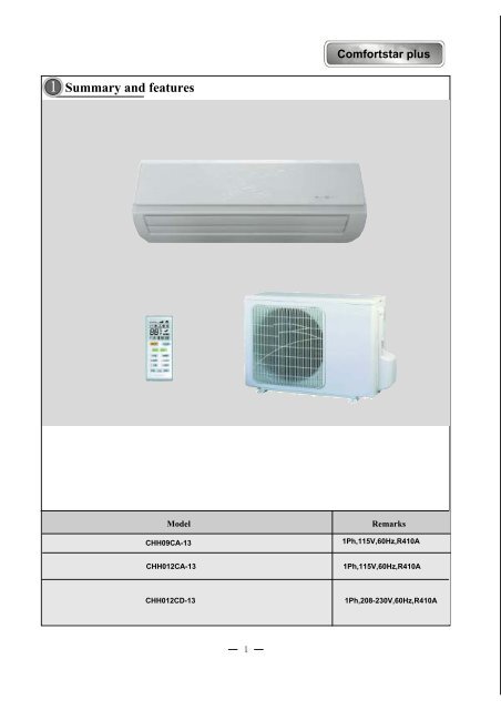
Comfortstar plus<br />
1 <strong>Summary</strong> <strong>and</strong> <strong>features</strong><br />
Model<br />
CHH09CA-13<br />
Remarks<br />
1Ph,115V,60Hz,R410A<br />
CHH012CA-13<br />
1Ph,115V,60Hz,R410A<br />
CHH012CD-13<br />
1Ph,208-230V,60Hz,R410A
Models & specifications<br />
Model CHH09CA-13 CHH012CA-13 CHH012CD-13<br />
Function<br />
Cooling &Heating<br />
Working Temp. Range (Indoor)<br />
60.8 o F-86 o F<br />
Operation Condition Range (Outdoor)(Cooling/heating) 60.8 o F-129 o F/-4-75.2F<br />
Power supply 115V/1Ph/60Hz 208-230V/1Ph/60Hz<br />
Rated current (A)(Cooling/Heating) 6.4/7 10/10.45 5/5.45<br />
LRA of compressor (A) 33 33 33<br />
Fuse or Breaker (A) 15 25<br />
15<br />
Refrigerant <strong>and</strong> Charge* (Ounce)R410a 42 44 44<br />
Size of power supply wire<br />
AWG12<br />
Size of connecting wire between condenser <strong>and</strong><br />
AWG18<br />
evaporator<br />
Piping connection (Gas/Liquid) (inch) (½ / ¼)<br />
Maximum line run (ft) 66<br />
Maximum elevation between condenser <strong>and</strong><br />
39<br />
evaporator (ft)<br />
Climate type<br />
T1<br />
Waterproof level<br />
IP×4<br />
Net weight (indoor/outdoor) (lb) 18.7/88.18 24.3/88.18<br />
Dimension (in) Indoor 30.3x9.8x7.5 35.7×11.4×7.68<br />
Dimension(in) Outdoor 33.38x21.27x12.6<br />
* The pre-charged refrigerant is good for 26 feet line set. For the system required longer line set than 26 feet, please add<br />
additional 0.22 Oz /ft refrigerant into the system.<br />
*The working pressure of suction line for the 3 models above: 123.3-145 PSI(Cooling)/406.1-464PSI(Heating)
2<br />
Specifications <strong>and</strong> technical parameters<br />
Model<br />
CHH09CA-13<br />
Function<br />
COOLING<br />
Rated Voltage<br />
115V<br />
Frequency(Hz) 60HZ<br />
HEATING<br />
Rated Capacity (Btu/h)<br />
10400 12800<br />
Rated Input (W) (High/St<strong>and</strong>ard) 1200/730 1400/800<br />
Rated Current (A)<br />
6.4 7<br />
Air Flow Volume (m 3 /h) (H/M/L) 600<br />
Dehumidifying Volume (l/h) 1.2<br />
SEER / HSPF<br />
16 8<br />
Indoor<br />
unit<br />
Model of Indoor Unit<br />
CHH09CA-13(I)<br />
Fan Motor Speed (r/min)<br />
1160/1010/890<br />
(H/M/L)<br />
Output of Fan Motor (w)<br />
14<br />
Input Power of Heater (w)<br />
/<br />
Fan Motor Capacitor (uF) 1.0<br />
Fan Motor RLA(A) 0.14<br />
Fan Type-Piece<br />
Cross flow fan – 1<br />
Diameter-Length (in) φ 3.8-23<br />
Evaporator<br />
Aluminum fin-copper tube<br />
Pipe Diameter (in) Φ 0.28<br />
Row-Fin Gap(in) 2-0.055<br />
Coil length (l) x height (H) x coil<br />
22.83x9x1<br />
width (L)(in)<br />
Swing Motor Model<br />
MP28VA<br />
Output of Swing Motor (W)<br />
2<br />
Fuse (A)<br />
PCB3.15A transformer0.2A<br />
Sound Pressure Level dB (A)<br />
40/ 36/ 33<br />
(H/M/L)<br />
Dimension (W/D/H)( in)<br />
Dimension of Package<br />
(W/D/H)( in)<br />
Net Weight /Gross Weight (lb)<br />
32.67×8.86×11.22<br />
33.66×10.7×13.22<br />
18.7/27.6<br />
2
Comfortstar plus<br />
Outdoor<br />
unit<br />
Model of Outdoor Unit<br />
Compressor Manufacturer/trademark<br />
Compressor Model<br />
Compressor Type<br />
L.R.A. (A)<br />
Compressor RLA(A)<br />
Compressor Power Input(W)<br />
Overload Protector<br />
Throttling Method<br />
Starting Method<br />
Working Temp Range ()<br />
Condenser<br />
Pipe Diameter (in)<br />
Rows-Fin Gap(in)<br />
Coil length (l) x height (H) x coil width<br />
(L)(<br />
Fan Motor Speed (rpm)<br />
Output of Fan Motor (W)<br />
Fan Motor RLA(A)<br />
Fan Motor Capacitor (uF)<br />
Air Flow Volume of Outdoor Unit<br />
3<br />
Fan Type-Piece<br />
Fan Diameter (in)<br />
Defrosting Method<br />
Climate Type<br />
Isolation<br />
Moisture Protection<br />
Permissible Excessive Operating<br />
Pressure for the Discharge<br />
Permissible Excessive Operating<br />
Pressure Sound Pressure for the Suction Level dB Side(MPa) (A) (H/M/L)<br />
CHH09C A-13(O)<br />
SANYO<br />
C-6RZ092H1AB<br />
Twin rotory<br />
33<br />
3.92<br />
960<br />
Int11l-3979<br />
Capillary throttling<br />
Transducer starting<br />
-7T43<br />
Aluminum fin-copper tube<br />
0.37<br />
2-0.05<br />
25.4X20X1.73<br />
830±20<br />
30<br />
0.3<br />
2.5<br />
1800<br />
Axial fan –1<br />
15.75<br />
Auto defrost<br />
T1<br />
I<br />
IP24<br />
3.8<br />
1.2<br />
55<br />
Connec<br />
tion<br />
Pipe<br />
Dimension (W/D/H)( in)<br />
Dimension of Package (W/D/H)( mm)<br />
Net Weight /Gross Weight (lb)<br />
Refrigerant Charge (oz)<br />
Length (ft)<br />
Gas additional charge(oz/ft)<br />
Outer Diameter<br />
Max Distance<br />
33.38X12.6X21.27<br />
34.6X14.2X23.2<br />
88.18/99.2<br />
R410A / 42<br />
26<br />
0.22<br />
Liquid Pipe (mm)<br />
Φ6(1/4”)<br />
Gas Pipe (mm)<br />
Φ12(1/2”)<br />
Height (ft) 39<br />
Length (ft) 66<br />
If there are any changes in the specifications <strong>and</strong> parameters in the above table, Please refer to the nameplate of the unit.
2<br />
Specifications <strong>and</strong> technical parameters<br />
Model<br />
CHH012CA-13<br />
Function<br />
COOLING<br />
Rated Voltage<br />
115V<br />
Frequency(Hz) 60HZ<br />
HEATING<br />
Rated Capacity (Btu/h)<br />
13900 14000<br />
Rated Input (W) (High/ St<strong>and</strong>ard )<br />
1450/1100 1500/1200<br />
Rated Current (A)<br />
10 10.45<br />
Air Flow Volume (m 3 /h) (H/M/L) 600<br />
Dehumidifying Volume (l/h) 1.2<br />
SEER / HSPF<br />
16 7.7<br />
Indoor<br />
unit<br />
Model of Indoor Unit<br />
CHH012CA-13(I)<br />
Fan Motor Speed (r/min)<br />
1350/1200/1110<br />
(H/M/L)<br />
Output of Fan Motor (w)<br />
22<br />
Input Power of Heater (w)<br />
/<br />
Fan Motor Capacitor (uF) 1.0<br />
Fan Motor RLA(A) 0.152<br />
Fan Type-Piece<br />
Cross flow fan – 1<br />
Diameter-Length (in) φ 3.63-24.3<br />
Evaporator<br />
Aluminum fin-copper tube<br />
Pipe Diameter (in) Φ0.276<br />
Row-Fin Gap(in) 2-0.055<br />
Coil length (l) x height (H) x coil<br />
26.81x12.77x1.5<br />
width (L)(in)<br />
Swing Motor Model<br />
MP28EA<br />
Output of Swing Motor (W) 2<br />
Fuse (A)<br />
Controller3.15 transformer0.2<br />
Sound Pressure Level dB (A)<br />
43 / 40 / 39<br />
(H/M/L)<br />
Dimension (W/D/H)( in)<br />
Dimension of Package<br />
(W/D/H)( in)<br />
Net Weight /Gross Weight (lb)<br />
32.7×8.86×11.2<br />
34.4×12.3×14.6<br />
24.3/33<br />
4
Comfortstar plus<br />
Outdoor<br />
unit<br />
Model of Outdoor Unit<br />
CHH012CA-13(O)<br />
Compressor Manufacturer/trademark<br />
SANYO<br />
Compressor Model<br />
C-6RZ092H1AB<br />
Compressor Type<br />
Twin rotory<br />
L.R.A. (A)<br />
33<br />
Compressor RLA(A) 3.92<br />
Compressor Power Input(W) 960<br />
Overload Protector<br />
Int11l-3979<br />
Throttling Method<br />
Capillary throttling<br />
Starting Method<br />
Transducer starting<br />
Working Temp Range () -7~43<br />
Condenser<br />
Aluminum fin-copper tube<br />
Pipe Diameter (in) 0.37<br />
Rows-Fin Gap(in) 2-0.05<br />
Coil length (l) x height (H) x coil width<br />
25.4X20X1.73<br />
(L)(<br />
Fan Motor Speed (rpm)<br />
830+20<br />
Output of Fan Motor (W) 30<br />
Fan Motor RLA(A) 0.3<br />
Fan Motor Capacitor (uF) 2.5<br />
Air Flow Volume of Outdoor Unit 1800<br />
3<br />
Fan Type-Piece<br />
Fan Diameter (in)<br />
Axial fan –1<br />
15.75<br />
Defrosting Method<br />
Climate Type<br />
Isolation<br />
Moisture Protection<br />
Permissible Excessive Operating<br />
Auto defrost<br />
T1<br />
I<br />
IP24<br />
3.8MPa<br />
Pressure for the Discharge<br />
Permissible Excessive Operating<br />
1.2MPa<br />
Pressure Sound Pressure for the Suction Level dB Side(MPa) (A) (H/M/L)<br />
55<br />
Connec<br />
tion<br />
Pipe<br />
Dimension (W/D/H)( in)<br />
Dimension of Package (W/D/H)( mm)<br />
Net Weight /Gross Weight (lb)<br />
Refrigerant Charge (oz)<br />
Length (ft)<br />
Gas additional charge(oz/ft)<br />
Outer Diameter<br />
Max Distance<br />
Liquid Pipe (mm)<br />
Gas Pipe (mm)<br />
Height (ft)<br />
Length (ft)<br />
33.38X12.6X21.27<br />
34.6X14.2X23.2<br />
88.18/99.2<br />
R410A / 44<br />
26<br />
0.22<br />
Φ6(1/4”)<br />
Φ12(1/2”)<br />
39<br />
66<br />
If there are any changes in the specifications <strong>and</strong> parameters in the above table, Please refer to the nameplate of the unit.<br />
5
2<br />
Specifications <strong>and</strong> technical parameters<br />
Model<br />
Function<br />
Rated Voltage<br />
Frequency(Hz)<br />
COOLING<br />
60HZ<br />
CHH012CD-13<br />
208V230V<br />
HEATING<br />
Rated Capacity (Btu/h)<br />
Rated Input (W) (High/ St<strong>and</strong>ard)<br />
13200 15900<br />
1450/1100 1500/1200<br />
Rated Current (A)<br />
5 5.45<br />
Air Flow Volume (m 3 /h) (H/M/L) 600<br />
Dehumidifying Volume (l/h) 1.2<br />
SEER / HSPF 15 7.7<br />
Indoor<br />
unit<br />
Model of Indoor Unit<br />
Fan Motor Speed (r/min)<br />
(H/M/L)<br />
Output of Fan Motor (w)<br />
Input Power of Heater (w)<br />
Fan Motor Capacitor (uF)<br />
Fan Motor RLA(A)<br />
Fan Type-Piece<br />
Diameter-Length (in)<br />
Evaporator<br />
Pipe Diameter (in)<br />
Row-Fin Gap(in)<br />
Coil length (l) x height (H) x coil<br />
width (L)(in)<br />
Swing Motor Model<br />
Output of Swing Motor (W)<br />
Fuse (A)<br />
Sound Pressure Level dB (A)<br />
(H/M/L)<br />
CHH012CD-13(I)<br />
1350/1200/1110<br />
22<br />
/<br />
1<br />
0.152<br />
Cross flow fan – 1<br />
φ3.63—24.3<br />
Aluminum fin-copper tube<br />
Φ0.27<br />
2-0.05<br />
26.8×12.76×1.5<br />
MP28EA<br />
2<br />
Controller3.15 transformer0.2<br />
43 / 40 / 39<br />
Dimension (W/D/H)( in)<br />
Dimension of Package<br />
(W/D/H)( in)<br />
Net Weight /Gross Weight (lb)<br />
32.7×8.86×11.2<br />
34.4×12.3×14.6<br />
24.3/33<br />
6
Comfortstar plus<br />
Outdoor<br />
unit<br />
Connec<br />
tion<br />
Pipe<br />
Model of Outdoor Unit<br />
Compressor Manufacturer/trademark<br />
Compressor Model<br />
Compressor Type<br />
L.R.A. (A)<br />
Compressor RLA(A)<br />
Compressor Power Input(W)<br />
Overload Protector<br />
Throttling Method<br />
Starting Method<br />
Working Temp Range ()<br />
Condenser<br />
Pipe Diameter (in)<br />
Rows-Fin Gap(in)<br />
Coil length (l) x height (H) x coil width<br />
(L)(<br />
Fan Motor Speed (rpm)<br />
Output of Fan Motor (W)<br />
Fan Motor RLA(A)<br />
Fan Motor Capacitor (uF)<br />
Air Flow Volume of Outdoor Unit<br />
3<br />
Fan Type-Piece<br />
Fan Diameter (in)<br />
Defrosting Method<br />
Climate Type<br />
Isolation<br />
Moisture Protection<br />
Permissible Excessive Operating<br />
Pressure for the Discharge<br />
Permissible Excessive Operating<br />
Pressure Sound Pressure for the Suction Level dB Side(MPa) (A) (H/M/L)<br />
Sound Power Level dB (A) (H/M/L)<br />
Dimension (W/D/H)( in)<br />
Dimension of Package (W/D/H)( mm)<br />
Net Weight /Gross Weight (lb)<br />
Refrigerant Charge (oz)<br />
Length (ft)<br />
Gas additional charge(oz/ft)<br />
Outer Diameter<br />
Max Distance<br />
CHH012CD-13(O)<br />
SANYO<br />
C-6RZ092H1AB<br />
Twin rotory<br />
33<br />
3.92<br />
960<br />
Int11l-3979<br />
Capillary throttling<br />
Transducer starting<br />
-7T43<br />
Aluminum fin-copper tube<br />
0.37<br />
2-0.05<br />
25.4X20X1.73<br />
830±20<br />
30<br />
0.3<br />
2.5<br />
1800<br />
Axial fan –1<br />
15.75<br />
Auto defrost<br />
T1<br />
I<br />
IP24<br />
3.8<br />
1.2<br />
55<br />
65<br />
33.38X12.6X21.27<br />
34.6X14.2X23.2<br />
88.18/99.2<br />
R410A / 44<br />
26<br />
0.22<br />
Liquid Pipe (mm)<br />
Φ6(1/4”)<br />
Gas Pipe (mm)<br />
Φ12(1/2”)<br />
Height (ft)<br />
39<br />
Length (ft)<br />
66<br />
If there are any changes in the specifications <strong>and</strong> parameters in the above table, Please refer to the nameplate of the unit.<br />
7
3<br />
Part name<br />
Air inlet<br />
Indoor Unit<br />
Front panel<br />
Guide louver<br />
Air outlet<br />
Receiving window<br />
LED board<br />
wrapping tape<br />
Wireless remote controll<br />
Outdoor Unit<br />
Air inlet<br />
Drainage hose<br />
Connecting pipe <strong>and</strong> connection wire<br />
Air outlet<br />
8
Comfortstar plus<br />
4<br />
Overall <strong>and</strong> Installing Dimension<br />
UOverall <strong>and</strong> Installing Dimension of Indoor Unit<br />
Air inlet grill<br />
Left piping hole<br />
Top view<br />
Right piping hole<br />
Rear view<br />
Unitmm<br />
Wall-mounting plate<br />
9
UOverall <strong>and</strong> Installing Dimension of Outdoor Unit<br />
Unit: mm<br />
Bolt<br />
Nut<br />
Wrench<br />
10
Comfortstar plus<br />
Circuit Diagram<br />
CHH09CA-13;CHH012CA-13<br />
INDOOR UNIT<br />
These circuit diagrams are subject to change without notice. Please refer to the ones stuck on the machines.<br />
11
Comfortstar plus<br />
5 Circuit Diagram<br />
CHH012CD-13<br />
INDOOR UNIT<br />
OUTDOOR UNIT<br />
These circuit diagrams are subject to change without notice. Please refer to the ones stuck on the machines.<br />
12
Comfortstar plus<br />
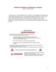
LOW AMBIENT CONTROL AND CONDENSATE PUMP DIAGRAM<br />
<br />
CHH09CA-13,CHH012CA-13,CHH012CD-13 CONDENSATE PUMP<br />
13
Comfortstar plus<br />
LOW AMBIENT CONTROL DIAGRAM<br />
<br />
14
6<br />
Function manual <strong>and</strong> operation method of remote controller<br />
Function manual of remote controller<br />
This function manual is applicable to D.C. Variable Frequency<br />
6.1.1 Temperature parameters<br />
Room set temperature (T set )<br />
Room ambient temperature (T amb )<br />
6.1.2 Fundamental functions<br />
After powered on, no matter when the compressor is started, the time interval between two startups<br />
cannot be less than 3 minutes.<br />
6.1.2.1 COOL mode<br />
6.1.2.1.1 The condition <strong>and</strong> process of cooling<br />
If T amb T set , COOL mode will act, the compressor <strong>and</strong> outdoor fan will run, <strong>and</strong> the indoor fan will run at the set<br />
speed.<br />
If T amb T set -2 ,<br />
the compressor will stop, the outdoor fan will delay 30 seconds to stop, <strong>and</strong> the indoor fan will<br />
run at the set speed.<br />
If T set -2T amb T set , the unit will keep running in the previous mode.<br />
In this mode, the reversal valve will not be powered on <strong>and</strong> the temperature setting range is 16~30 .<br />
The unit will adjust the running frequency of the compressor automatically according to the change of ambient<br />
temperature.<br />
Start cooling<br />
Tset<br />
Tamd<br />
Tset<br />
3min<br />
Original running state<br />
Stop cooling<br />
Compressor<br />
Outdoor fan<br />
Indoor fan<br />
Set fan speed<br />
6.1.2.1.2 Protection function<br />
Run<br />
Stop<br />
Antifreezing protection<br />
Under cooling <strong>and</strong> drying mode, after the compressor run about 10mins,when the pipe temp.of the<br />
evaporator is to low, the compressor will stop, the outdoor fan will stop after 30s, under cooling<br />
mode the indoor fan <strong>and</strong> swing motor will keep running in the original mode , under drying mode the<br />
indoor fan will run at low fan speed, the swing motor will run in the original mode. When antifreezing<br />
protection is eliminated <strong>and</strong> the compressor has stopped for 3 minutes, the unit will resume running in<br />
the original mode.<br />
The period of antifreezingprotection<br />
Compressor<br />
Outdoor fan<br />
Indoor fan<br />
3 min<br />
Overcurrent protection<br />
Run<br />
Stop<br />
If total current is high, the compressor will run in limited or dropped frequency. When total current goes on<br />
rising over the stated value, the compressor will stop, the outdoor fan will delay 30 seconds to stop.<br />
6.1.2.2 DRY mode<br />
6.1.2.2.1 The condition <strong>and</strong> process of drying<br />
15
Comfortstar plus<br />
If T amb >T set , DRY mode will act, the indoor fan, outdoor fan <strong>and</strong> compressor will run, <strong>and</strong> indoor fan will run at<br />
low speed<br />
If T set -2T amb T set , the unit will keep running in the original mode.<br />
If T amb
over the stated value, the compressor will stop, the outdoor fan will delay 30 seconds to stop.<br />
6.1.2.4 FAN mode<br />
In this mode, the indoor fan will run the fan in High, Med, Low <strong>and</strong> Auto mode. The compressor, outdoor fan<br />
<strong>and</strong> four-way valve will stop.<br />
In this mode, the temperature setting range is 16~30 .<br />
<br />
The unit will adjust the running frequency of the compressor automatically according to the change of ambient<br />
temperature.<br />
6.1.2.5 AUTO mode<br />
In this mode, the system selects COOL, HEAT <strong>and</strong> FAN mode automatically according to the change of ambient<br />
temperature. The protection function is the same with that of COOL/HEAT mode.<br />
The unit will adjust the running frequency of the compressor automatically according to the change of ambient<br />
temperature.<br />
6.1.3 Other control<br />
6.1.3.1 ON / OFF<br />
Each time the On/Off button of the remote controller is pressed, the On/Off state will switch once.<br />
6.1.3.2 MODE selection<br />
Press the MODE button on the remote controller to select <strong>and</strong> display the following modes:<br />
AUTO, COOL, DRY, FAN, <strong>and</strong> HEAT.<br />
6.1.3.3 TEMP. setting button<br />
Each time TEMP + or TEMP - button is pressed, the set temperature will be increased or decreased by 1 .<br />
Adjusting range is 16~30 . In AUTO mode, this button does not function.<br />
6.1.3.4 AUTO key<br />
When the unit is stop, press AUTO key,the unit will run under AUTO mode <strong>and</strong> the swing motor starts.<br />
When the unit is running, press AUTO key,the unit will be stopped.<br />
AUTO/STOP<br />
6.1.3.5 Timer control<br />
The unit is turned on or off according to the timer set by the remote controller.<br />
H<strong>and</strong>ling switch<br />
6.1.3.6 Sleep control<br />
When the air conditioner is in COOL or DRY mode, after Sleep mode has been set properly, the preset T set will<br />
be increased by 1 after the sleep program has run for 1 hour, <strong>and</strong> T set will be increased by another 1 after 2<br />
hours. T set has been increased by 2 totally in two hours. Then the unit will run at this set temperature <strong>and</strong> at<br />
the set speed.<br />
Set temp.T set<br />
T set +2<br />
T set +1<br />
1 h 2 h Above 2h<br />
T set<br />
When the air conditioner is in HEAT mode, after Sleep mode has been set properly, the preset T set will be<br />
decreased by 1 after the sleep program has run for 1 hour, <strong>and</strong> Tset will be decreased by another 1 after 2<br />
hours. T set has been increased by 2 totally in two hours. Then the unit will run at this set temperature <strong>and</strong> at the<br />
set speed.<br />
1 h 2 h Above 2h<br />
T set<br />
T set -1<br />
T set -2<br />
Set temp.T set<br />
In AUTO or FAN mode, the setting temp. will not change.<br />
17
Comfortstar plus<br />
6.1.3.7 Indoor fan control<br />
Use the remote controller to set the indoor fan running at HIGH, MED or LOW speed. At this time the fan will run<br />
at high, medium or low speed. It can also be set to AUTO <strong>and</strong> the indoor fan will select fan speed(HIGH, MED or<br />
LOW) automatically according to ambient temperature.<br />
There are at least 3mins <strong>and</strong> 30s delay for fan speed shift.<br />
6.1.3.8 Power supply for outdoor unit<br />
The power supply for outdoor unit is turned on in AUTO, COOL, HEAT <strong>and</strong> DRY mode under turn-on state.<br />
The power supply for outdoor unit will delay 3 minutes to turn off under turn-off state or in the FAN mode under<br />
turn-on state.<br />
6.1.3.9 Swing control<br />
Use the SWING button of the wireless remote control to control SWING On <strong>and</strong> Off. Swing will only act when<br />
indoor fan is running.After power on, the swing motor turns back to 0 position <strong>and</strong> closes the air outlet vent; if it<br />
does not preset swing, after the unit is turned on, it will turn to the max. air outlet D1 position; then turn back to L<br />
position under COOL mode.Under HEAT mode,the guide louver stays at D1;when in swinging state, it will swing<br />
between L1 <strong>and</strong> D1 position. When the unit is turned off, it will turn back to 0 position.<br />
6.1.3.10 Buzzer control<br />
When the unit is power on or receives remote control signal or the auto key be pressed,the buzzer will give out a beep.<br />
6.1.3.11 Power-off memory function<br />
Contents of memory: Mode; Swing; Set fan speed, Set temperature,Timing etc.<br />
Under turn-on state, when power off <strong>and</strong> power on, the power supply for outdoor unit will be turn on after 3mins .<br />
Under turn-off state, when power off <strong>and</strong> power on, the power supply for outdoor unit will be turn on immediately.<br />
6.1.3.12 Delay Protection of Compressor<br />
Under COOL; DRY; HEAT mode, before each time the compressor starts, there will be 3mins delay.<br />
6.1.4. Common protection function in each mode<br />
6.1.4.1 Overload protection<br />
Ttube:at cooling,it detects the temp. of outdoor heat exchanger,at heating,it detects the temp. of indoor heat exchanger.<br />
When Ttube is detected high, the compressor will run in limited frequency.When Ttube goes on rising over the stated<br />
value, the compressor will stop, under AUTO HEAT or HEAT mode, indoor fan will blow 60s at low fan speed <strong>and</strong><br />
then stop, under other mode, the indoor fan will run at set speed.<br />
6.1.4.2 Compressor discharge temperature protection<br />
When discharge temperature is too high to over the stated value, the compressor will stop, <strong>and</strong> When discharge temp.<br />
resume normal <strong>and</strong> the compressor has stopped for 3 minutes, the unit will resume its original operating status.<br />
6.1.4.3 Communication malfunction<br />
When not receiving correct signal for 3 minutes, the unit has communication malfunction <strong>and</strong> the outdoor unit<br />
stops, it is the same as normal stop when meeting the set temp..<br />
6.1.4.4 Module protection<br />
When module is in protection, the compressor will stop, after the compressor has stopped for 3 minutes, it will<br />
resume to running. During module protection period, the indoor unit displays malfunction <strong>and</strong> the whole unit stops.<br />
18
7 Disassembly procedures<br />
Disassembly procedures for indoor unit<br />
Operation procedures/pictures<br />
8.1.1 Disassembling the front panel <strong>and</strong><br />
electric box cover<br />
Unloose the clasps on both sides <strong>and</strong> lift the panel<br />
upward. Unplug the two connecting terminals of the<br />
display <strong>and</strong> slide out the rear clasp from the groove to<br />
take off the front panel.(you can use panel support bar<br />
to support the panel) Screw off the fixing screws of<br />
the electric box cover <strong>and</strong> open the electric box top cover to take it off.<br />
As shown in Fig.7-1<br />
Panel panel support<br />
bar<br />
Screw<br />
Electric box<br />
top cover<br />
Fig.7-1<br />
Filter<br />
Push the filter up to unloose the clasp to pull out the<br />
two filters.<br />
8.1.2<br />
As shown in Fig.7-2<br />
Filters<br />
Fig.7-2<br />
Disassembling the guide louver<br />
Bend the guide louver with strength <strong>and</strong> let out the<br />
rotating shaft from the groove to take off the guide<br />
louver. As shown in Fig.7-3<br />
Guide louver<br />
Fig.7-3<br />
19
Comfortstar plus<br />
Operation procedures/pictures<br />
Disassembling the front panel body<br />
Unclench the 3 screw covers <strong>and</strong> screw off the 3 pieces<br />
of screws that fix the panel body. Unloose the front <strong>and</strong><br />
rear clasps to take off the panel body.<br />
As shown in Fig.7-4<br />
screw<br />
screw covers<br />
Fig.7-4<br />
Disassembling the electric box cover<br />
Unloose the 3 clasps to take off the electric box cover.<br />
As shown in Fig.7-5<br />
cl<br />
clasps<br />
Fig.7-5<br />
Disassembling the water-tray assy<br />
Unloose the clasp on the left side <strong>and</strong> unplug the<br />
connecting terminal of the stepping motor. Carefully<br />
to remove the water-tray assy because the drainage pipe clasp<br />
is placed here. As shown in Fig7-6, 7-7<br />
water-tray assy<br />
cc<br />
Fig.7-6<br />
connecting terminal<br />
Fig.7-7<br />
20
Operation procedures/pictures<br />
7.1.7 Disassembling the electric box<br />
Screw off the two pieces of screws that fix the electric<br />
box <strong>and</strong> unloose the clasp. Pull out the tube sensor,<br />
unloose the grounding nut <strong>and</strong> unplug the motor<br />
connecting terminal take out the electric box.<br />
As shown in Fig 7-8<br />
Tube sensor<br />
Screws<br />
Grounding nut<br />
Motor connecting<br />
terminal<br />
7.1.8 ||||||||| Disassembling the evaporator assy<br />
Screw off the screws that fix the evaporator, one piece<br />
on the left <strong>and</strong> two pieces on the right. As shown in Fig<br />
7-9, 7-10<br />
Lift the left end of the evaporator slightly upward with<br />
your end <strong>and</strong> push it rearward to let out the side clasps<br />
of the evaporator from the groove. Take out the<br />
evaporator carefully <strong>and</strong> pay attention to protecting the<br />
connecting pipe.<br />
Screw<br />
Fig 7-8<br />
Fig 7-9<br />
Screws<br />
7.1.9 Disassembling the motor<br />
Screw off the 3 pieces of screws that fix the motor<br />
clamp to take off the motor clamp. As shown in Fig.7-<br />
11<br />
Screw off the fixing nut that fixes the cross flow fan to<br />
pull out the motor from the cross flow fan. As shown in<br />
Fig.7-12<br />
Screws<br />
Right motor<br />
clamp<br />
Fig 7-10<br />
Fig 7-11<br />
7.1.10 Disassembling the cross flow fan<br />
Refer to the above steps to take out the cross flow fan<br />
from the base plate after taking out the motor.<br />
s<br />
screws<br />
motor<br />
cross flow fan<br />
Fig 7-12<br />
21
Comfortstar plus<br />
Disassembly Procedures for Outdoor Unit<br />
Operating Procedures / Photos<br />
Disassemble Top Cover <strong>and</strong> H<strong>and</strong>le<br />
Use screwdriver to unscrew the screw at the<br />
h<strong>and</strong>le, <strong>and</strong> remove the h<strong>and</strong>le. Unscrew the three<br />
screws around the top cover, <strong>and</strong> remove the top<br />
cover.<br />
(refer to Figure 7-13)<br />
Top Cover<br />
screw<br />
screw H<strong>and</strong>le<br />
Figure 7-13<br />
Disassemble Rear Grill<br />
Screw out the 4 self tapping screws on<br />
rear side plate <strong>and</strong> chassis of valve supporter<br />
<strong>and</strong> side plate of condenser can take off rear grill.<br />
(refer to Figure 7-14)<br />
screw<br />
Grill<br />
Figure 7-14<br />
2 Disassemble Components of Panel<br />
Screw out the 5 tapping screws on panel <strong>and</strong><br />
chassis of valve supporter <strong>and</strong> side plate of condenser<br />
can take off components of panel.<br />
(refer to Figure 7-15)<br />
Panel<br />
screw<br />
Figure 7-15<br />
22
Operating Procedures / Photos<br />
Disassemble electric install plate<br />
Screw out the 3 bolts that fixing on electric install<br />
plate, plug out lead inserter of compressor <strong>and</strong><br />
fan to take off electric install plate.<br />
(refer to Figure 7-16,7-17)<br />
electric box cover<br />
bolts<br />
Figure 7-16<br />
Disassemble Right Side Plate<br />
bolts<br />
Figure 7-17<br />
Screw out the 5 bolts on rear side plate can take<br />
off right side plate.<br />
(refer to Figure 7-18)<br />
bolts<br />
Disassemble axial-flow vane<br />
Figure 7-18<br />
Loosen tighten nut by spanner to take off nuts,<br />
spring washer, flat washer, <strong>and</strong> take off axial-flow<br />
vane forcibly.<br />
tighten nut<br />
(refer to Figure 7-19)<br />
axial-flow vane<br />
Figure 7-19<br />
23
Comfortstar plus<br />
Operating Procedures / Photos<br />
Disassemble Motor <strong>and</strong> Motor Support<br />
Unscrew the four tapping screws fixing the motor,<br />
<strong>and</strong> remove the motor. Unscrew the two tapping<br />
screws fixing the motor support, <strong>and</strong> lift the motor<br />
support to remove it.<br />
(refer to Figure 7-20)<br />
Motor Support<br />
tapping screws<br />
Motor<br />
Figure 7-20<br />
Disassemble 4-Way Valve<br />
Screw off the holding nut of the 4-way valve coil<br />
<strong>and</strong> remove the coil. Use wet cotton cloth to wrap 4-way valve<br />
the 4-way valve, unsold the four soldering points<br />
connecting the 4-way valve, <strong>and</strong> remove the soldering points<br />
4-way valve. Be quick during the unsoldering holding nut<br />
process, pay attention to keep the wrapping cloth<br />
wet <strong>and</strong> do not allow the soldering flame to burn<br />
the compressor lead-out cable.<br />
(Note: only after discharging all freon).<br />
Figure 7-21<br />
(refer to Figure 7-21)<br />
Disassemble Capillary Subassembly<br />
Unsolder the soldering points connecting the<br />
capillary subassembly <strong>and</strong> the other pipelines, <strong>and</strong><br />
remove the capillary subassembly.<br />
Capillary Subassembly<br />
(refer to Figure 7-22)<br />
Figure 7-22<br />
24
Operating Procedures / Photos<br />
Disassemble Valves<br />
Unscrew the two screws fixing the big valve,<br />
unsolder the soldering point between the big<br />
valve <strong>and</strong> the return-air duct <strong>and</strong> remove the big<br />
valve.<br />
(Note: when unsoldering the soldering point, use<br />
wet cloth to completely wrap the big valve to<br />
prevent valve body from being harmed by high<br />
temperature.)<br />
Unscrew the two screws fixing the small valve,<br />
unsolder the soldering point connecting the small<br />
valve <strong>and</strong> the fork type pipe, <strong>and</strong> remove the small<br />
valve.<br />
(refer to Figure 7-23)<br />
Disassemble Compressor<br />
Small Valves<br />
Big Valves<br />
bolts<br />
Figure 7-23<br />
Unscrew the three nuts with washers at the foot of<br />
the compressor. Unsolder the soldering points at<br />
the suction <strong>and</strong> the discharge pipes of the compressor,<br />
carefully remove the pipes <strong>and</strong> take out the<br />
compressor.<br />
(refer to Figure 7-24)<br />
compressor bolt<br />
Figure 7-24<br />
25
Comfortstar plus<br />
8 Exploded View <strong>and</strong> Components <strong>and</strong> Parts List<br />
Exploded View of Components <strong>and</strong> Parts of Indoor Unit<br />
CHH09CA-13(I),CHH012CA-13(I),CHH012CD-13(I)<br />
26
Components <strong>and</strong> Parts List of Indoor Unit<br />
No Description<br />
Part Code<br />
CHH09CA-13(I)<br />
Qty<br />
1 Wall-Mounting Frame 01252220 1<br />
2 Rear Case 222020012 1<br />
3 Evaporator Assy 01002070 1<br />
4 Cross-Flow Fan 10352001 1<br />
5 Ring of Bearing 76712203 1<br />
6 Drain Hose 05232411 1<br />
7 Water Tray 20182070 1<br />
8 Swing Louver 10582002 1<br />
9 Swing Linkage<br />
1<br />
10 Front Grill 01472005 1<br />
11 Front Case 20002210 1<br />
12 Screw Cap 24252006 3<br />
13 Air Filter 11122002 2<br />
14 Panel 20002812 1<br />
15 Panel 20002814 1<br />
16 Remote Control 30511010 1<br />
17 Light Cover 22242031 1<br />
18 Display Board 30545706 1<br />
19 Display Cover<br />
1<br />
20 Shield Board 26112044 1<br />
21 Guide Louver 26112033 1<br />
22 Guide Louver 26112034 1<br />
23 Step Motor 15212110 1<br />
24 Right Motor Clamp<br />
1<br />
25 Motor<br />
150121082 1<br />
26 Motor Bearing Holder<br />
1<br />
27 Electric Box 201021781 1<br />
28 Electric Box Cover 22242030 1<br />
29 Terminal Board<br />
42011233 1<br />
30 Covering Plate 201220064 1<br />
31 Main PCB<br />
30039146 1<br />
32 Room Sensor<br />
390000451 1<br />
33 Tube Sensor<br />
390000591 1<br />
34 Transformer<br />
43110254 1<br />
35 Wire Clamp 71010003 1<br />
36 Rear Clamp 26112430 1<br />
27
Comfortstar plus<br />
Components <strong>and</strong> Parts List of Indoor Unit<br />
No Description<br />
Part Code<br />
CHH012CA-13(I)<br />
Qty<br />
1 Wall-Mounting Frame 01252384 1<br />
2 Rear Case 22202051 1<br />
3 Evaporator Assy 010021811 1<br />
4 Cross-Flow Fan 10352005 1<br />
5 Ring of Bearing 76712015 1<br />
6 Drain Hose 05232411 1<br />
7 Water Tray 201820302 1<br />
8 Swing Louver 10512041 1<br />
9 Swing Linkage 10582439 1<br />
10 Front Grill 01472004 1<br />
11 Front Case 20002295 1<br />
12 Screw Cap 24252007 3<br />
13 Air Filter 11122440 2<br />
14 Panel 20002828 1<br />
15 Panel 20002831 1<br />
16 Remote Control YB1B4F 30511010 1<br />
17 Light Cover 22242031 1<br />
18 Display Board 30545557 1<br />
19 Display Cover 22432071 1<br />
20 Shield Board 26112048 1<br />
21 Guide Louver 26112043 1<br />
22 Guide Louver 26112042 1<br />
23 Step Motor MP28EA 15212105 1<br />
24 Right Motor Clamp 26112429 1<br />
25 Motor<br />
150120524 1<br />
26 Motor Bearing Holder 26152423 1<br />
27 Electric Box 201021081 1<br />
28 Electric Box Cover 222420175 1<br />
29 Terminal Board T4B3A 42011233 1<br />
30 Covering Plate 20102123 1<br />
31 Main PCB<br />
30039145 1<br />
32 Room Sensor 15K 390000451 1<br />
33 Tube Sensor 20K 390000591 1<br />
34 Transformer 57X25F 43110257 1<br />
35 Wire Clamp 71010003 1<br />
36 Rear Clamp 26112430 1<br />
28
Components <strong>and</strong> Parts List of Indoor Unit<br />
No Description<br />
Part Code<br />
CHH012CD-13(I)<br />
Qty<br />
1 Wall-Mounting Frame 01252384 1<br />
2 Rear Case 22202050 1<br />
3 Evaporator Assy 010021811 1<br />
4 Cross-Flow Fan 10352005 1<br />
5 Ring of Bearing 76712015 1<br />
6 Drain Hose 05232411 1<br />
7 Water Tray 201820302 1<br />
8 Swing Louver 10512041 1<br />
9 Swing Linkage 10582439 1<br />
10 Front Grill 01472004 1<br />
11 Front Case 20002295 1<br />
12 Screw Cap 24252007 3<br />
13 Air Filter 11122440 2<br />
14 Panel 20002828 1<br />
15 Panel 20002831 1<br />
16 Remote Control YB1B4F 30511010 1<br />
17 Light Cover 22242031 1<br />
18 Display Board 30545557 1<br />
19 Display Cover 22432071 1<br />
20 Shield Board 26112048 1<br />
21 Guide Louver 26112043 1<br />
22 Guide Louver 26112042 1<br />
23 Step Motor MP28EA 15212105 1<br />
24 Right Motor Clamp 26112429 1<br />
25 Motor FN22P 15012061 1<br />
26 Motor Bearing Holder 26152423 1<br />
27 Electric Box 201021081 1<br />
28 Electric Box Cover 222420175 1<br />
29 Terminal Board T4B3A 42011233 1<br />
30 Covering Plate 20102123 1<br />
31 Main PCB 9H82 30039085 1<br />
32 Room Sensor 15K 390000451 1<br />
33 Tube Sensor 20K 390000591 1<br />
34 Transformer 57X25F 43110257 1<br />
35 Wire Clamp 71010003 1<br />
36 Rear Clamp 26112430 1<br />
29
Exploded View of Outdoor unit<br />
CHH09CA-13(O)<br />
30
No Description<br />
Part Code<br />
CHH09CA-13(O)<br />
Qty<br />
1 Front Panel 01533007 1<br />
2 Clap Board 01233012 1<br />
3 Reactor Box C 01413504 1<br />
4 PFC Inductance 0.8mH/20A 99070120 1<br />
5 Drainage Connecter 06123401 1<br />
6 Reactor Support Assy 01203102 1<br />
7 Overload Protector 00183003 1<br />
8 Compressor C-6RZ092H1AB 00102004 1<br />
9 Compressor Gasket 76710236 3<br />
10 Bolt 70210007 3<br />
11 Nut 70310011 3<br />
12 Valve Support 01713041 1<br />
13 Right Side Plate Assy 01303071 1<br />
14 Valve 1/2" 07100006 1<br />
15 Valve 1/4" 07100003 1<br />
16 Capillary Assy 1<br />
17 One Way Valve 07130103 1<br />
18 4-Way Valve 430004032 1<br />
19 4-way Rever-sing Valve Component 03023670 1<br />
20 Electric Cover Assy 01413086 1<br />
21 4-way Valve Coil 430004002 1<br />
22 capacitor clamp 1<br />
23 capacitor 1<br />
24 Terminal Board A 42010255 1<br />
25 Electric Box 2 01413025 1<br />
26 electrical filter 1<br />
27 capacitor box1 1<br />
28 capacitor box2 1<br />
29 Electric Box 20113001 1<br />
30 PCB 1<br />
31 Temperature Sensor 3900012123 1<br />
32 Sensor 20K 39000071 1<br />
33 Exhaust Gas Temperature Sensor 50K 39000016 1<br />
34 Electric Box Cover 01413048 1<br />
35 Rectifier S25VB60 46010602 1<br />
36 Sensor Insert 42020063 1<br />
37 Radiator 49010213 1<br />
38 Rear Grill 01473030 1<br />
39 Condenser Assy 0110350713 1<br />
40 Top Cover Assy 01253261 1<br />
41 Motor Support Assy 017030521 1<br />
42 Motor FW30K 15013067 1<br />
43 Axial Flow Fan 10333414 1<br />
44 Nut 70310131 1<br />
45 Front Grill 22413011 1<br />
-31
Exploded View of Outdoor unit<br />
CHH012CA-13(O)<br />
32
No<br />
Description<br />
p1b 1 WG06006622 60829<br />
Part Code<br />
CHH012CA-13(O)<br />
1 Front Panel 01533007 1<br />
2 Clap Board 01233012 1<br />
3 Reactor Box C 01413504 1<br />
4 PFC Inductance 0.8mH/20A 99070120 1<br />
5 Drainage Connecter 06123401 1<br />
6 Reactor Support Assy 01203102 1<br />
7 Overload Protector 00183003 1<br />
8 Compressor C-6RZ092H1AB 00102004 1<br />
9 Compressor Gasket 76710236 3<br />
10 Bolt 70210007 3<br />
11 Nut 70310011 3<br />
12 Valve Support 01713041 1<br />
13 Right Side Plate Assy 01303071 1<br />
14 Valve 1/2" 07100006 1<br />
15 Valve 1/4" 07100003 1<br />
16 Capillary Assy 03103301 1<br />
17 One Way Valve 07130103 1<br />
18 4-Way Valve 430004032 1<br />
19 4-way Rever-sing Valve Component 03023670 1<br />
20 Electric Cover Assy 01413086 1<br />
21 4-way Valve Coil 430004002 1<br />
22 Terminal Board A 42010255 1<br />
22 capacitor clamp 1<br />
23 capacitor 1<br />
24 Terminal Board A 42010255 1<br />
25 Electric Box 2 01413025 1<br />
26 electrical filter 1<br />
27 capacitor box1 1<br />
28 capacitor box2 1<br />
29 Electric Box 20113001 1<br />
30 PCB W9M32A 30039155 1<br />
31 Temperature Sensor 3900012123 1<br />
32 Sensor 20K 39000071 1<br />
33 Exhaust Gas Temperature Sensor 50K 39000016 1<br />
34 Electric Box Cover 01413048 1<br />
35 Rectifier S25VB60 46010602 1<br />
36 Sensor Insert 42020063 1<br />
37 Radiator 49010213 1<br />
38 Rear Grill 01473030 1<br />
39 Condenser Assy 0110350713 1<br />
40 Top Cover Assy 01253261 1<br />
41 Motor Support Assy 017030521 1<br />
42 Motor FW30K 15013067 1<br />
43 Axial Flow Fan 10333414 1<br />
44 Nut 70310131 1<br />
45 Front Grill 22413011 1<br />
Qty<br />
-33
Exploded View of Outdoor Unit<br />
CHH012CD-13(O)<br />
34
Comfortstar plus<br />
Components <strong>and</strong> Parts List of Outdoor Unit<br />
No Description<br />
Part Code<br />
CHH012CD-13(O)<br />
Qty<br />
1 Front Panel 01533007 1<br />
2 Clap Board 01233012 1<br />
3 Reactor Box C 01413504 1<br />
4 PFC Inductance 0.8mH/20A 99070120 1<br />
5 Drainage Connecter 06123401 1<br />
6 Reactor Support Assy 01203102 1<br />
7 Overload Protector 00183003 1<br />
8 Compressor C-6RZ092H1AB 00102004 1<br />
9 Compressor Gasket 76713006 3<br />
10 Bolt 70210007 3<br />
11 Nut 70310011 3<br />
12 Valve Support 01713041 1<br />
13 Right Side Plate Assy 01303071 1<br />
14 Valve 1/2" 07100006 1<br />
15 Valve 1/4" 07100003 1<br />
16 Capillary Assy 03103301 1<br />
17 One Way Valve 07130103 1<br />
18 4-Way Valve 430004032 1<br />
19 4-way Rever-sing Valve Component 03023670 1<br />
20 Electric Cover Assy 01413086 1<br />
21 4-way Valve Coil 430004002 1<br />
22 Terminal Board A 42010255 1<br />
23 Electric Box 2 01413025 1<br />
24 Electric Box 20113001 1<br />
25 PCB W9M32A 30039155 1<br />
26 Temperature Sensor 3900012123 1<br />
27 Sensor 20K 39000071 1<br />
28 Exhaust Gas Temperature Sensor 50K 39000016 1<br />
29 Electric Box Cover 01413048 1<br />
30 Rectifier S25VB60 46010602 1<br />
31 Sensor Insert 42020063 1<br />
32 Radiator 49010213 1<br />
33 Rear Grill 01473030 1<br />
34 Condenser Assy 0110350713 1<br />
35 Top Cover Assy 01253261 1<br />
36 Motor Support Assy 017030521 1<br />
37 Motor FW30K 15013067 1<br />
38 Axial Flow Fan 10333414 1<br />
39 Nut 70310131 1<br />
40 Front Grill 22413011 1<br />
35
9 Troubleshooting<br />
Common section<br />
Analysis in this section is used for D.C. Variable Frequency Series. Before analysis, you can diagnose<br />
according to the code displayed on indoor unit or indicator display on outdoor unit. (Refer to 9.2 Malfunction<br />
display section).<br />
Breaker tripped<br />
or fuse burnt out<br />
When the breaker is set ON, it will<br />
trip at once<br />
When the unit is turned on, the<br />
breaker will trip in a few minutes<br />
Measure the insulating resistance<br />
for grounding to confirm whether<br />
there is electrical leakage or short<br />
circuit in the unit<br />
Insulation malfunction of line or componen<br />
in the air conditioner. Insulation breakdow<br />
occurs after radiation, which causes shor<br />
circuit or electricity leakage. Measure<br />
insulating resistance or use one-by-on<br />
elimination method;<br />
Malfunction of fuse. Replace it.<br />
No power supply<br />
Check power supply circuit<br />
Air<br />
conditi<br />
oner<br />
cannot<br />
start up<br />
Air conditioner<br />
does not response<br />
after powered on.<br />
(The buzzer does<br />
not sound after the<br />
plug is connected<br />
<strong>and</strong> the unit does<br />
not response after<br />
the remote<br />
controller is used<br />
to turn it on)<br />
The power plug is not or poorly<br />
connected<br />
Controller fuse is burnt out<br />
Loose or poor contact of transformer<br />
connection, or transformer malfunction<br />
Check <strong>and</strong> plug well plug, make<br />
loosen contact firm<br />
Change control fuse<br />
Secure the wire connection: measure<br />
the output voltage of the transformer<br />
<strong>and</strong> replace it if the value is wrong<br />
The controller is broken<br />
Replace the controller<br />
Remote<br />
controller does<br />
not receive signal<br />
(When powered<br />
on, the buzzer<br />
will send out a<br />
sound, unless it is<br />
broken)<br />
Batteries of remote controller are low<br />
Malfunction of remote controller<br />
Loose or poor connection of receiving<br />
head<br />
Receiving head is broken<br />
Change battery<br />
First press the "AUTO" button of the<br />
manual switch. If there is no response,<br />
check according to the above method;<br />
if it is normal after the button is<br />
pressed, check if the installation<br />
location <strong>and</strong> wire connection of the<br />
receiving head are correct. If correct,<br />
replace the receiving head, or the<br />
remote controller.<br />
36
Comfortstar plus<br />
Improper setting of temperature<br />
Adjust the set temperature<br />
Whether cooling (heating) load<br />
is proper<br />
Check the estimated load of cooling (heating)<br />
Leakage or shortage of refrigerant<br />
Vacuumize after leakage detection<br />
<strong>and</strong> leakage repair. Charge refrigerant<br />
according to specification.<br />
Malfunction of<br />
refrigerant flow<br />
Leakage occurs between high <strong>and</strong><br />
low pressure inside compressor<br />
Malfunction of four-way valve<br />
Replace the compressor<br />
Replace the four-way valve<br />
Partial blockage of capillary<br />
Replace the capillary<br />
Poor cooling<br />
(heating) effect<br />
Poor thermal insulation of connecting<br />
pipe of indoor <strong>and</strong> outdoor unit<br />
Blockage of cooling system<br />
Use the method of observing condensation<br />
on the evaporator <strong>and</strong> pressure value of<br />
high pressure manometer to see whether<br />
the system is blocked <strong>and</strong> carry out<br />
corresponding h<strong>and</strong>ling on the system<br />
Ensure that both thick pipe <strong>and</strong> thin pipe are insulated<br />
well. The exposed part of the connector <strong>and</strong> copper pipe<br />
must be insulated as well.<br />
Heat exchanger of outdoor unit<br />
is blocked<br />
Air filters are blocked<br />
Clean the dust accumulated on the<br />
surface of the heat exchanger<br />
Clean the filter<br />
Air circulation<br />
is insufficient<br />
Fan speed is set too slow<br />
Fan speed turns low<br />
Improper installation location<br />
for outdoor unit<br />
Set the fan speed to high or medium<br />
speed<br />
Damage of<br />
capacitor<br />
damaged<br />
Damage of<br />
motor<br />
Replace<br />
capacitor<br />
Replace the motor<br />
Outdoor unit should be installed in a<br />
place with well ventilation<br />
the<br />
Outdoor temperature is too high<br />
Flashing or awning can be installed appropriately. If the<br />
max. cooling capacity cannot be satisfied, replacement of<br />
the air conditioner is recommended.<br />
Indoor sealability is inadequate; too many<br />
people go in <strong>and</strong> out frequently; there is<br />
heating unit in the room.<br />
Maintain a certain degree of indoor sealability. Try not to<br />
use appliance with high amount of heat.<br />
37
Abnormal power supply of outdoor unit<br />
Check the circuit according to circuit diagram<br />
When unit is<br />
cooling or<br />
heating, both<br />
compressor <strong>and</strong><br />
outdoor fan don't<br />
run<br />
Damage of outdoor main control board<br />
Breakage of outdoor power module<br />
Improper setting of temperature<br />
Replace the main control board<br />
Replace the power module<br />
Adjust the set temperature<br />
When unit is<br />
cooling or<br />
heating, the<br />
compressor runs<br />
but outdoor fan<br />
doesn't run<br />
Breakage of outdoor fan motor<br />
Wrong wire connection<br />
Breakage of outdoor main control board<br />
Replace the fan motor<br />
Wire according to the circuit diagram<br />
Replace the main control board<br />
Breakage of outdoor fan capacitor<br />
Replace the fan capacitor<br />
Malfunction of compressor<br />
Replace the compressor<br />
When cooling or<br />
heating, outdoor<br />
fan runs, but<br />
compressor<br />
doesn't run.<br />
Poor contact of connection between the<br />
main control board <strong>and</strong> module<br />
Abnormal input of power module<br />
Abnormal output of power module<br />
Re-fasten the connection<br />
Check if input is 320V. If not, replace the<br />
rectifier<br />
Replace the power module<br />
When cooling or<br />
heating, outdoor<br />
fan runs, but<br />
compressor<br />
doesn't run.<br />
Compressor temperature is too high<br />
Wrong wiring<br />
Damage of outdoor main control board<br />
Cool the compressor for 30 min before running<br />
Wire according to the circuit diagram<br />
Replace the outdoor main control board<br />
Fan doesn't run<br />
when FAN mode<br />
is set<br />
Burn-out or broken wire of indoor fan<br />
motor<br />
Wrong wiring<br />
Circuit break or damage of fan motor<br />
capacitor<br />
Repair or change the fan motor<br />
Wire according to the circuit diagram<br />
Replace the indoor main control board<br />
38
Comfortstar plus<br />
Water leakage<br />
Blockage or breakage of drainage hose<br />
Wrap of refrigerant pipe connector is not<br />
tight enough<br />
Replace the drainage hose<br />
Re-wrap <strong>and</strong> make it tight<br />
Fan of indoor unit contacts other parts<br />
Adjust fan location<br />
There is foreign substance in indoor unit<br />
Take out the foreign substance<br />
Abnormal sound<br />
<strong>and</strong> shake<br />
Compressor shakes too much<br />
Touch of pipeline of outdoor unit<br />
Touch of inner plates<br />
Adjust support washer of the compressor <strong>and</strong><br />
tighten loose bolts<br />
Separate the touched pipeline<br />
1. Tighten connecting screws<br />
2.Stick shock-absorbing clay between plates<br />
Touch of outdoor unit fan blade with<br />
outer case<br />
Abnormal sound inside compressor<br />
Adjust louver position<br />
Replace compressor<br />
Abnormal electromagnetic sound inside<br />
four-way valve when heating<br />
Short circuit inside electromagnetic valve.<br />
Replace the electromagnetic valve<br />
Notes<br />
1.When repairing, before the voltage between module PN is measured below 50V, do not touch any terminal<br />
to avoid electric shock.<br />
2.When replacing power module <strong>and</strong> rectifier, be sure to spread the radiating paste evenly.<br />
39
12.2 Malfunction display section<br />
D.C. Variable Frequency Series<br />
When malfunction or protection occurs in the air conditioner, corresponding code will be displayed on the screen<br />
of the indoor unit <strong>and</strong> the indicator of outdoor unit will blink accordingly as well. When protection or malfunction<br />
is eliminated, display will be back to normal<br />
E4: Compressor discharge protection<br />
E5: Low voltage overcurrent protection<br />
E6: Communication malfunction<br />
Display code <strong>and</strong><br />
malfunction<br />
description of<br />
indoor unit<br />
F1: Indoor environmental sensor open or short circuit (the malfunction is detected for 30s<br />
continuously)<br />
F2: Indoor evaporator sensor open or short circuit (the malfunction is detected for 30s continuously)<br />
F3: Outdoor environmental sensor open or short circuit (the malfunction is detected for 30s<br />
continuously)<br />
F4: Outdoor condenser sensor open or short circuit (the malfunction is detected for 30s<br />
continuously)<br />
F5: Outdoor discharge sensor open or short circuit (after the compressor runs for 3 min, the<br />
malfunction is detected for 3s continuously)<br />
H1: Defrosting<br />
H3: Compressor overload protection<br />
H4: System malfunction (i.e. overload protection)<br />
H5: IPM module protection<br />
(Mainboard) Yellow light blinks 1 time<br />
(Mainboard) Yellow light blinks 2 times<br />
Compressor is running (this is normal condition<br />
<strong>and</strong> the display of indoor unit is normal)<br />
Defrosting (display H1)<br />
Indicator display<br />
of outdoor unit<br />
(Mainboard) Yellow light blinks 3 times<br />
(Mainboard) Yellow light blinks 4 times<br />
(Mainboard) Yellow light blinks 5 times<br />
(Mainboard) Yellow light blinks 6 times<br />
(Mainboard) Yellow light blinks 7 times<br />
(Mainboard) Yellow light blinks 8 times<br />
Antifreezing protection (display of indoor unit<br />
displays is normal)<br />
IPM module protection (corresponds to H5 of<br />
indoor unit)<br />
Overcurrent protection (corresponds to E5 of<br />
indoor unit)<br />
Overload protection (corresponds to H4 of<br />
indoor unit)<br />
Discharge protection (corresponds to E4 of<br />
indoor unit)<br />
Compressor overload protection (corresponds to<br />
H3 of indoor unit)<br />
(Mainboard) Red light blinks 1 time<br />
Limited frequency(current)<br />
(Mainboard) Red light blinks 2 times<br />
Dropped frequency (Discharge)<br />
40
Comfortstar plus<br />
(Mainboard) Red light blinks 3 times<br />
Limited frequency(overload)<br />
(Mainboard) Red light blinks 4 times<br />
Dropped frequency (Antifreeze Protection)<br />
Indicator display<br />
of outdoor unit<br />
(Mainboard) Red light blinks 5 times<br />
(Mainboard) Red light blinks 6 times<br />
Malfunction of outdoor tube sensor<br />
Malfunction of outdoor environmental sensor<br />
(Mainboard) Red light blinks 7 times<br />
Malfunction of outdoor discharge sensor<br />
(Mainboard) Red light blinks 8 times<br />
(Mainboard) Green light blinks<br />
Starting temperature is reached. This is normal<br />
condition <strong>and</strong> display of indoor unit is normal<br />
Communication is normal<br />
Note: Malfunction display : blind 0.5s; stop 0.5s, there is 2s' interval between two malfunction displays<br />
Analysis or h<strong>and</strong>ling of some of the malfunction display:<br />
1. Compressor discharge protection (E4):<br />
Possible reasons: shortage of refrigerant; blockage of air filter; poor ventilation or air flow short pass<br />
for condenser; the system has noncondensing gas (such as air, water etc.); blockage of capillary assy<br />
(including filter); leakage inside four-way valve causes incorrect operation; malfunction of<br />
compressor; malfunction of protection relay; malfunction of discharge sensor; outdoor temperature too<br />
high.<br />
H<strong>and</strong>ling method: refer to the malfunction analysis in the above section.<br />
2. Low voltage overcurrent protection (E5):<br />
Possible reason: Sudden drop of supply voltage.<br />
3. Communication malfunction (E6):<br />
H<strong>and</strong>ling method: Check if communication signal cable is connected reliably<br />
4 Sensor open or short circuit (F1, F2, F3, F4, F5):<br />
H<strong>and</strong>ling method: Check whether sensor is normal, connected with the corresponding position on the<br />
controller <strong>and</strong> if damage of lead wire is found<br />
5. Compressor overload protection (H3):<br />
Possible reasons: insufficient or too much refrigerant; blockage of capillary <strong>and</strong> increase of suction temp.;<br />
improper running of compressor, burning in or stuck of bearing, damage of discharge valve;<br />
malfunction of protector.<br />
H<strong>and</strong>ling method: adjust refrigerant amount; replace the capillary; replace the compressor; use<br />
universal meter to check if the contactor of compressor is fine when it is not overheated, if not replace<br />
the protector.<br />
6. System malfunction (H4):<br />
i.e. overload protection. When tube temperature (Check the temperature of outdoor heat exchanger<br />
when cooling <strong>and</strong> check the temperature of indoor heat exchanger when heating) is too high,<br />
protection will be activated.<br />
Possible reasons: Outdoor temperature is too high when cooling; insufficient outdoor air circulation;<br />
refrigerant flow malfunction.<br />
please refer to the malfunction analysis in the previous section for h<strong>and</strong>ling method .<br />
-41
7. Module protection (H5):<br />
H<strong>and</strong>ling method:<br />
Check if the voltage between power module P <strong>and</strong> N is too low <strong>and</strong><br />
if the current is too high. In normal condition, voltage between P <strong>and</strong><br />
N should be about 320V.<br />
Abnormal<br />
Normal<br />
Check power supply circuit of outdoor unit (if PTC resistance<br />
rectifying bridge, reactor, capacitance etc. is ok).<br />
Temperature of power module is too high,<br />
which causes overheating protection<br />
Protection is still displayed<br />
Check if radiating paste is spread<br />
evenly or radiating sticker is stuck<br />
well; if screws of power module<br />
is tightened<br />
Reinstall power module <strong>and</strong><br />
re-spread radiating paste or<br />
stick radiating sticker on the<br />
radiator of power module.<br />
Confirm the setting status of outdoor unit (cooling)<br />
Normal<br />
Poor radiation, heat exchanger<br />
is dirty<br />
Remove obstructions<br />
<strong>and</strong> clean<br />
Confirm if outdoor fan motor is running; unplug the<br />
three connecting wires between U, V, W of compressor<br />
<strong>and</strong> power module. Turn on the unit to see if outdoor<br />
fan runs normally (about 1 minute)<br />
Outdoor fan runs<br />
Confirm if there is voltage output <strong>and</strong> balance of<br />
voltage between any two phases of U, V <strong>and</strong> W.<br />
Outdoor fan stops<br />
Measure the voltage of outdoor<br />
fan connector<br />
Yes<br />
Whether module type<br />
is correct<br />
No<br />
Replace the power module<br />
No voltage<br />
Replace the mainboard<br />
of outdoor unit<br />
Replace the fan<br />
motor<br />
Normal voltage<br />
Abnormal<br />
Replace the module<br />
with correct type<br />
Normal<br />
Measure the three-phase<br />
resistance of compressor<br />
Normal<br />
Whether cylinder of<br />
compressor is stuck<br />
Replace the<br />
compressor<br />
Abnormal<br />
If the unit runs normally after connected<br />
with the new compressor for trial run, the<br />
cylinder of original compressor is stuck<br />
42