Download - Panasonic Biomedical
Download - Panasonic Biomedical
Download - Panasonic Biomedical

Create successful ePaper yourself
Turn your PDF publications into a flip-book with our unique Google optimized e-Paper software.
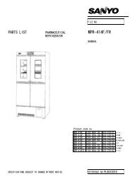
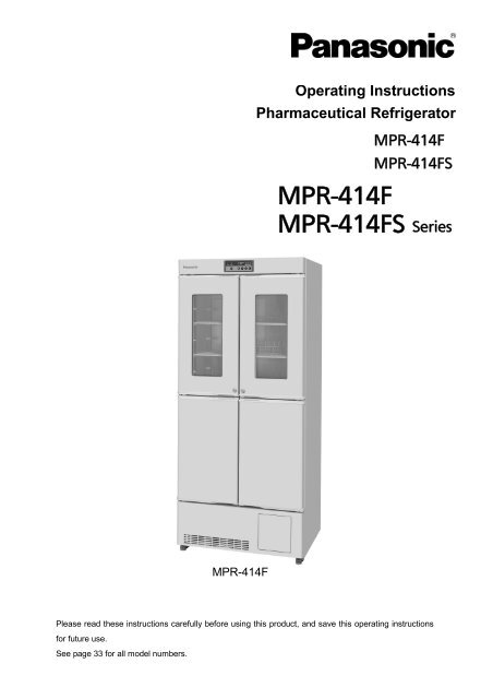
Operating Instructions<br />
Pharmaceutical Refrigerator<br />
MPR-414F<br />
MPR-414FS<br />
MPR-414F<br />
MPR-414FS Series<br />
MPR-414F<br />
Please read these instructions carefully before using this product, and save this operating instructions<br />
for future use.<br />
See page 33 for all model numbers.
CONTENTS<br />
INTRODUCTION P. 3<br />
PRECAUTIONS FOR SAFE OPERATION P. 4<br />
ENVIRONMENTAL CONDITIONS P. 8<br />
REFRIGERATOR COMPONENTS P. 9<br />
Control panel P. 11<br />
INSTALLATION SITE P. 12<br />
INSTALLATION P. 13<br />
START-UP OF UNIT P. 14<br />
TEMPERATURE SETTING P. 15<br />
KEY LOCK FUNCTION P. 16<br />
DEFROSTING OF FREEZER P. 16<br />
DEFROSTING P. 17<br />
ALARM TEMPERATURE SETTING P. 18<br />
SETTING OF ALARM RESUME TIME P. 20<br />
REMOTE ALARM TERMINAL P. 20<br />
ALARMS AND SAFETY FUNCTIONS P. 21<br />
ROUTINE MAINTENANCE<br />
Cleaning P. 22<br />
Replacement of lamp P. 23<br />
TROUBLESHOOTING P. 24<br />
DISPOSAL OF UNIT P. 24<br />
OPTIONAL COMPONENT<br />
Temperature recorder P. 29<br />
Installation of temperature recorder P. 30<br />
SPECIFICATIONS P. 32<br />
PERFORMANCE P. 33<br />
SAFETY CHECK SHEET P. 34<br />
2
INTRODUCTION<br />
Read this operating instructions carefully before using the appliance and follow the instructions for<br />
safety operation.<br />
Our company never guarantee any safety if the appliance is used for any objects other than intended<br />
use or used by any procedures other than those mentioned in this operating instructions.<br />
Keep this operating instructions in an adequate place to refer to it as necessary.<br />
The contents of the operating instructions will be subjected to change without notice due to the<br />
improvement of performance or functions.<br />
Contact our sales representative or agent if any page of the operating instructions is lost or page order<br />
is incorrect.<br />
Contact our sales representative or agent if any point in this operating instructions is unclear or if there<br />
are any inaccuracies.<br />
No part of this operating instructions may be reproduced in any form without the expressed written<br />
permission of our company.<br />
CAUTION<br />
Our company guarantees the product under certain warranty conditions. Our company in no<br />
way shall be responsible for any loss of content or damage of content.<br />
3
PRECAUTIONS FOR SAFE OPERATION<br />
It is imperative that the user complies with this operating instructions<br />
as it contains important safety advice.<br />
Items and procedures are described so that you can use this unit correctly and safely.<br />
If the precautions advised are followed, this will prevent possible injury to the user and<br />
any other person.<br />
Precautions are illustrated in the following way:<br />
WARNING<br />
Failure to observe WARNING signs could result in a hazard to personnel<br />
possibly resulting in serious injury or death.<br />
CAUTION<br />
Failure to observe CAUTION signs could result in injury to personnel and<br />
damage to the unit and associated property.<br />
Symbol shows;<br />
this symbol means caution.<br />
this symbol means an action is prohibited.<br />
this symbol means an instruction must be followed.<br />
Be sure to keep this operating instructions in a place accessible to users of this unit.<br />
< Label on the unit ><br />
This mark is labeled on the cover in which the electrical components of high voltage<br />
are enclosed to prevent the electric shock.<br />
The cover should be removed by a qualified engineer or a service personnel only.<br />
4
PRECAUTIONS FOR SAFE OPERATION<br />
WARNING<br />
Do not use the unit outdoors. Current leakage or electric shock may result if the unit is exposed to<br />
rain water.<br />
Only qualified engineers or service personnel should install the unit. The installation by<br />
unqualified personnel may cause electric shock or fire.<br />
Install the unit on a sturdy floor and take an adequate precaution to prevent the unit from<br />
turning over. If the floor is not strong enough or the installation site is not adequate, this may result<br />
in injury from the unit falling or tipping over.<br />
Never install the unit in a humid place or a place where it is likely to be splashed by water.<br />
Deterioration of the insulation may result which could cause current leakage or electric shock.<br />
Never install the unit in a flammable or volatile location. This may cause explosion or fire.<br />
Never install the unit where acid or corrosive gases are present as current leakage or electric<br />
shock may result due to corrosion.<br />
Always ground (earth) the unit to prevent electric shock. If the power supply outlet is not<br />
grounded, it will be necessary to install a ground by qualified engineers.<br />
Never ground the unit through a gas pipe, water main, telephone line or lightning rod. Such<br />
grounding may cause electric shock in the case of an incomplete circuit.<br />
Connect the unit to a power source as indicated on the rating label attached to the unit. Use of<br />
any other voltage or frequency other than that on the rating label may cause fire or electric shock.<br />
Never store volatile or flammable substances in this unit if the container cannot be sealed. These<br />
may cause explosion or fire.<br />
Do not insert metal objects such as a pin or a wire into any vent, gap or any outlet on the unit.<br />
This may cause electric shock or injury by accidental contact with moving parts.<br />
Use this unit in safe area when treating the poison, harmful or radiate articles. Improper use<br />
may cause bad effect on your health or environment.<br />
Turn off the power switch (if provided) and disconnect the power supply to the unit prior to any<br />
repair or maintenance of the unit in order to prevent electric shock or injury.<br />
Do not touch any electrical parts (such as power supply plug) or operate switches with a wet<br />
hand. This may cause electric shock.<br />
5
PRECAUTIONS FOR SAFE OPERATION<br />
WARNING<br />
Ensure you do not inhale or consume medication or aerosols from around the unit at the time of<br />
maintenance. These may be harmful to your health.<br />
Never splash water directly onto the unit as this may cause electric shock or short circuit.<br />
Never put containers with liquid on the unit as this may cause electric shock or short circuit when<br />
the liquid is spilled.<br />
Never bind, process, or step on the power supply cord, or never damage or break the power<br />
supply plug. A broken supply cord or plug may cause fire or electric shock.<br />
Do not use the supply cord if its plug is loose. Such supply cord may cause fire or electric shock.<br />
Never disassemble, repair, or modify the unit yourself. Any such work carried out by an<br />
unauthorized person may result in fire, or electric shock or injury due to a malfunction.<br />
Disconnect the power supply plug if there is something wrong with the unit. Continued<br />
abnormal operation may cause electric shock or fire.<br />
When removing the plug from the power supply outlet, grip the power supply plug, not the cord.<br />
Pulling the cord may result in electric shock or fire by short circuit.<br />
Disconnect the power supply plug before moving the unit. Take care not to damage the power<br />
cord. A damaged cord may cause electric shock or fire.<br />
Disconnect the power plug when the unit is not used for long periods. Keeping the connection<br />
may cause electric shock, current leakage, or fire due to the deterioration of insulation.<br />
If the unit is to be stored unused in an unsupervised area for an extended period, ensure that<br />
children do not have access and that doors cannot be closed completely.<br />
The disposal of the unit should be accomplished by appropriate personnel. Remove doors to<br />
prevent accidents such as suffocation.<br />
Do not put the packing plastic bag within reach of children as suffocation may result.<br />
6
PRECAUTIONS FOR SAFE OPERATION<br />
CAUTION<br />
Use a dedicated power source (a dedicated circuit with a breaker) as indicated on the rating label<br />
attached to the unit. A branched circuit may cause fire resulting from abnormal heating.<br />
Connect the power supply plug to the power source firmly after removing the dust on the plug.<br />
A dusty plug or improper insertion may cause a heat or ignition.<br />
Never store corrosive substances such as acid or alkali in this unit if the container cannot be<br />
sealed. These may cause corrosion of inner components or electric parts.<br />
Check the setting when starting up of operation after power failure or turning off of power<br />
switch. The stored items may be damaged due to the change of setting.<br />
Be careful not to tip over the unit during movement to prevent damage or injury.<br />
Prepare a safety check sheet when you request any repair or maintenance for the safety of service<br />
personnel.<br />
7
ENVIRONMENTAL CONDITIONS<br />
This equipment is designed to be safe at least under the following conditions (based on the IEC 61010-1):<br />
Indoor use;<br />
Altitude up to 2000 m;<br />
Temperature 5 o C to 40 o C<br />
Maximum relative humidity 80% for temperature up to 31 o C decreasing linearly to 50% relative humidity<br />
at 40 o C;<br />
Mains supply voltage fluctuations up to ±10% of the nominal voltage;<br />
Transient overvoltages up to the levels of OVERVOLTAGE CATEGORY Ⅱ;<br />
Temporary OVERVOLTAGES occurring on the mains supply;<br />
Applicable pollution degree of the intended environment (POLLUTION DEGREE 2 in most cases);<br />
8
REFRIGERATOR COMPONENTS<br />
1<br />
2<br />
3<br />
4<br />
5<br />
6<br />
17<br />
16<br />
10<br />
7<br />
8<br />
9<br />
10<br />
Refrigerator<br />
11<br />
15<br />
14<br />
13<br />
Freezer<br />
12<br />
4<br />
MPR-414F with drawers (optional component)<br />
9
REFRIGERATOR COMPONENTS<br />
1. Circulating fan: This is for cooling the refrigerator uniformly. Fan is installed inside the enclosure.<br />
Do not insert anything into the enclosure. The air exhaust vent is located at the upper of the fan.<br />
2. Air intake vent: Ensure this vent is never blocked. Failure to do so will result in unstable<br />
temperature distribution in the refrigerator.<br />
3. Control panel: The operation status is displayed on this panel. And the temperature setting is<br />
available through this panel. Refer to page 11 for the details.<br />
4. Mounting space for a temperature recorder: Space for a temperature recorder is available<br />
separately. See page 29 for the mounting of the temperature recorder.<br />
5. Lamp: This lamp lights up when the refrigerator door is open to illuminate the chamber.<br />
6. Glass window: Water can sometimes condense on the glass in areas of high humidity. Wipe off<br />
the condensation with a dry soft cloth. (MPR-414FS has no glass window.)<br />
7. Magnetic door gasket: This prevents the cool air from escaping. Always keep clean.<br />
8. Movable center pillar: The pillar contact the door gasket firmly when the door is closed and functions<br />
as a block between the chamber and outer air. When the door is opened, the pillar angle is changed by<br />
90 degree. Take care not to change the pillar angle.<br />
9. Protective sheet: The stored material may be frozen if it is put on the chamber bottom directly.<br />
Always put the sheet in the refrigerator compartment (upper and lower left chamber).<br />
10. Lock: Turn a key clockwise through 180 degree to lock the door. The right side lock is for the right<br />
upper and lower doors and left side lock is for the left upper and lower doors.<br />
11. Access port (rear): This port allows cables to be passed into the cabinet.<br />
12. Leveling feet: Use these bolts to adjust the height and level the unit for installation.<br />
13. Remote alarm terminal: This is used to alarm the abnormality to the remote location. See page 20<br />
for the details.<br />
14. Power switch (also functions as a circuit breaker): The power switch also used as a circuit<br />
breaker. Normally put a cover on the switch. The round button under the power switch is a leakage test<br />
button. The operation check of the circuit breaker can be performed by pressing this button. But note<br />
the power supply to the unit is disconnected when this button is pressed.<br />
15. Drawer: Drawers are available as an optional component (MPR-41R).<br />
16. Shelf (at the opening between upper and lower chamber): Ensure this surface is never blocked<br />
by the stored items so that the cool air can be circulated into the lower chamber.<br />
17. Cool air exhaust vent: Ensure this vent is never blocked. Note the items exposed to the direct air<br />
flow can be frozen.<br />
10
REFRIGERATOR COMPONENTS<br />
Control panel<br />
1 2<br />
3<br />
4<br />
5<br />
REFRIGERATOR<br />
DOOR<br />
FREEZER<br />
REF.<br />
FREEZ.<br />
10 9 8 7 6<br />
1. Door check lamp (DOOR): This lamp is lit when the door is open.<br />
2. Alarm lamp (ALARM): This lamp is flashed during alarm condition. Refer to page 18 “Alarm<br />
temperature setting”.<br />
3. Freezer indicator (FREEZER): This indicator is lit when the freezer is selected.<br />
4. Refrigerator indicator (REFRIGERATOR): This indicator is lit when the refrigerator is selected.<br />
5. Temperature display: This indicator shows the chamber temperature, set temperature, or error<br />
code.<br />
6. Numerical value shift key ( ): Pressing this key in the setting mode causes the numerical value to<br />
change. “ON-OFF” of key lock can be selected by pressing this key in the key lock mode.<br />
7. Digit shift key ( ): Pressing this key in set mode causes the changeable digits to move. Key lock<br />
is activated by pressing this key for more than 5 seconds in the temperature display mode. See “Key<br />
lock function” on page 16.<br />
8. Set key (SET): Pressing this key activates temperature set mode and the digit which can be set is<br />
flashed. By pressing the key again after setting, the set value is accepted.<br />
9. Display select key (REF./FREEZ.): By pressing this key, chamber temperature display of refrigerator<br />
or freezer and each setting is selected.<br />
10. Alarm buzzer stop key (BUZZER): Press this key to silence the buzzer in the event that the alarm<br />
operates and buzzer sounds. See page 21 for the details.<br />
11
INSTALLATION SITE<br />
To operate this unit properly and to obtain maximum performance, install the unit in a location with the<br />
following conditions:<br />
A location not subjected to direct sunlight<br />
Do not install the unit under direct sunlight. Installation in a location subjected to direct sunlight cannot<br />
obtain the intended performance.<br />
A location with adequate ventilation<br />
Leave at least 10 cm around the unit for ventilation. Poor ventilation will result in a reduction of the<br />
performance and consequently the failure.<br />
A location away from heat generating sources<br />
Avoid installing the unit near heat-emitting appliances such as a heater or a boiler etc. Heat can<br />
decrease the intended performance of the unit.<br />
A location with little temperature change<br />
Install the unit under stable ambient temperature. The allowable ambient temperature is between -5 and<br />
+35 o C.<br />
A location with a sturdy and level floor<br />
Always install the unit on a sturdy and level floor. The uneven floor or tilted installation may cause failure<br />
or injury. Install the unit in stable condition to avoid the vibration or noise. Unstable condition may<br />
cause vibration or noise.<br />
WARNING<br />
Install the unit on a sturdy floor. If the floor is not strong enough or the installation site is not adequate,<br />
this may result in injury from the unit falling or tipping over.<br />
Select a level and sturdy floor for installation. This precaution will prevent the unit from tipping.<br />
Improper installation may result in water spillage or injury from the unit tipping over.<br />
A location not prone to high humidity<br />
Install the unit in the ambient of 80% R.H. or less humidity. Installation under high humidity may cause<br />
current leakage or electric shock.<br />
WARNING<br />
Do not use the unit outdoors. Current leakage or electric shock may result if the unit is exposed to rain<br />
water.<br />
Never install the unit in a humid place or a place where it is likely to be splashed by water.<br />
Deterioration of the insulation may result which could cause current leakage or electric shock.<br />
CAUTION<br />
The unit starts defrosting frequently due to excessive frost on the evaporator if it is installed in high<br />
temperature and high humidity location. The chamber temperature goes up to approximately 10 o C<br />
temporarily during defrosting.<br />
A location without flammable or corrosive gas<br />
Never install the unit in a flammable or volatile location. This may cause explosion or fire or may result in<br />
the current leakage or electric shock by the corrosion of the electrical components.<br />
A location without the possibility of anything fall<br />
Avoid installing the unit in the location where anything can fall down onto the unit. This may cause the<br />
breakdown or failure of the unit.<br />
12
INSTALLATION<br />
1. Remove the packaging materials and tapes<br />
Remove all transportation packaging materials and<br />
tapes. Open the doors and ventilate the unit. If the<br />
outside panels are dirty, clean them with a diluted<br />
neutral dishwashing detergent. (Undiluted detergent<br />
can damage the plastic components. For the dilution,<br />
refer to the instruction of the detergent.) After the<br />
cleaning with the diluted detergent, always wipe it off<br />
with a wet cloth. Then wipe off the panels with a dry<br />
cloth.<br />
Note:<br />
Remove the cable tie banding the power supply cord.<br />
Prolonged banding may cause the corrosion of the cord<br />
coating.<br />
Leveling feet<br />
Fig.1<br />
2. Adjusting the leveling foot<br />
Extend the leveling feet by rotating them<br />
counterclockwise to contact them to the floor.<br />
Ensure the unit is level. (Fig.1)<br />
3. Fixing the unit<br />
Two fixtures are attached to the rear of the frame. Fix<br />
the frame to the wall with these fixtures and rope or<br />
chain. (Fig.2)<br />
Fixture<br />
Fig.2<br />
4. Ground (earth)<br />
WARNING<br />
Use a power supply outlet with ground (earth) to prevent electric shock. If the power supply outlet is<br />
not grounded, it is necessary to install a ground by qualified engineers.<br />
Never ground the unit through a gas pipe, water main, telephone line or lightning rod. Such<br />
grounding may cause electric shock in the case of an incomplete circuit.<br />
Note:<br />
If an instrument requiring a power source is to be placed inside the cabinet, the cable can be lead through<br />
the access port on the back side of the cabinet. After using of the port, a rubber cap and insulation<br />
should be replaced to seal the access port. Failure to do this can affect the temperature uniformity inside<br />
the cabinet and lead to condensation on the outside of the access port.<br />
13
START-UP OF UNIT<br />
The following procedures should be adhered to for initial start-up and continuous operation.<br />
1. Connect the unit to dedicated power supply. Do not put any product in the unit at this time.<br />
Note:<br />
If the unit is unplugged or the power to the unit is interrupted, do not restart the unit for at least 5 minutes.<br />
This protects the compressor.<br />
2. On start-up, the alarm buzzer sometimes operates. In this case, stop the buzzer by pressing the alarm<br />
buzzer stop key (BUZZER).<br />
3. Set the desired temperature.<br />
4. Confirm that the chamber temperature is at the desired temperature.<br />
5. When you are satisfied that the unit is working correctly, begin slowly placing product into the chamber<br />
to minimize the temperature rise.<br />
Note:<br />
Fix the shelves securely. Place items on the shelves and leave a space between the walls of the cabinet<br />
and the contents to allow air circulation. Do not place items on the floor of the chamber.<br />
CAUTION<br />
This inner cabinet is refrigerated by the forced circulation of cooled air inside the chamber. Ensure that<br />
the intake and exhaust vents are not blocked. Adequate space should be provided between the items<br />
inside the unit to allow air circulation. Too much stock will result in temperature of about -2 o C around the<br />
exhaust vent when the set temperature is 2 o C. It is recommended to set the temperature to 4 o C or 5 o C<br />
when a large quantity of articles that should not be frozen are stored.<br />
The heat discharge pipe is attached inside of the rear frame. The rear frame is sometimes hot at the<br />
start-up of the operation. But this does not mean malfunction.<br />
14
TEMPERATURE SETTING<br />
Table 1 shows the basic operation method. Perform key operation in the sequence indicated in the table.<br />
The example in the table is based on the assumption that the refrigerator temperature is 4 o C and the<br />
freezer temperature is -25 o C.<br />
Note: The unit is set at the factory so that the refrigerator temperature is 5 o C and the freezer<br />
temperature is -20 o C.<br />
Table 1 Basic operation procedure (Example of setting: refrigerator; 4 o C, freezer; -25 o C)<br />
Operation Key operated Indication after operation<br />
1<br />
Connect to the power source and turn<br />
The current refrigerator or freezer<br />
-----<br />
on the power switch.<br />
temperature is displayed.<br />
2<br />
The refrigerator indicator lights and<br />
Select refrigerator (REF.)by<br />
REF.<br />
pressing display select key.<br />
FREEZ.<br />
the current refrigerator temperature<br />
is displayed.<br />
3 Press set key. SET<br />
The current set temperature is<br />
displayed and the second digit of<br />
the temperature display flashes.<br />
4<br />
Set to 004 by using digit shift key<br />
and numerical value shift key.<br />
5 Press set key. SET<br />
6<br />
Select freezer (FREEZ.) by pressing<br />
display select key.<br />
REF.<br />
FREEZ.<br />
7 Press set key. SET<br />
8<br />
Set to -25 by using digit shift key<br />
and numerical value shift key.<br />
9 Press set key. SET<br />
Pressing the key leads the flash of<br />
the first digit.<br />
Pressing the key shifts up the figure<br />
of the current digit.<br />
The value is stored in memory and<br />
the current refrigerator temperature<br />
is displayed.<br />
The freezer indicator lights<br />
and the current freezer<br />
temperature is displayed.<br />
The current set temperature is<br />
displayed and the second digit of<br />
the temperature display flashes.<br />
Pressing the key leads the flash of<br />
the first digit.<br />
Pressing the key shifts up the figure<br />
of the current digit.<br />
The value is stored in memory and<br />
the current freezer temperature<br />
is displayed.<br />
Note:<br />
If no key has been pressed for about 90 seconds in the temperature set mode, the display mode returns<br />
automatically to the temperature display mode. In this case, the chamber temperature setting is not changed.<br />
The effective temperature setting for refrigerator ranges between 2 and 14 o C.<br />
The stored items can be frozen partially when the set temperature of refrigerator is equal to or lower than<br />
3 o C.<br />
The freezer temperature can be set in the range between -15 and -35 o C. Remember that the guaranteed<br />
temperature with no load at an ambient temperature of 30 o C is -30 o C.<br />
15
KEY LOCK FUNCTION<br />
This unit incorporates a key lock feature which can inhibit the tampering using the keys on the control<br />
panel.<br />
The key lock is set to OFF at the factory.<br />
Display Mode Function<br />
L 0 Key lock OFF Temperature change enabled<br />
L 1 Key lock ON Temperature change disabled<br />
Table 2 Key lock setup procedure (Example: Key lock OFF ⇒ Key lock ON)<br />
Operation Key operated Indication after operation<br />
The current refrigerator or freezer<br />
temperature is displayed.<br />
1<br />
Press and hold the digit shift<br />
The first digit of the temperature<br />
key for about 5 seconds.<br />
display blinks.<br />
2<br />
Set the first digit to 1 with<br />
Pressing the key shifts up the figure<br />
the numerical value shift key.<br />
of the digit.<br />
3 Press the set key. SET<br />
Key lock is set to ON and the current<br />
refrigerator or freezer temperature is<br />
displayed.<br />
Note:<br />
Key lock can be set any time when the current refrigerator or freezer temperature is displayed.<br />
DEFROSTING OF FREEZER<br />
Table 3 below shows the procedure for defrosting of freezer or stopping the freezer operation.<br />
Table 3<br />
Operation Key operated Indication after operation<br />
1<br />
Select freezer (FREEZ.)by pressing REF. The current freezer temperature<br />
display select key.<br />
FREEZ. is displayed.<br />
2 Press the set key. SET<br />
The current set value is displayed<br />
and the second digit of the temperature<br />
display flashes.<br />
Pressing the key leads blink of the<br />
3<br />
Set to -00 by using digit shift key<br />
first digit of the temperature display.<br />
and numerical value shift key.<br />
Pressing the key shifts up the figure<br />
of the current digit.<br />
4 Press the set key. SET<br />
The value is stored in memory and<br />
the current freezer temperature and<br />
dF is displayed alfternately.<br />
(starting of defrosting)<br />
5 Check the defrosting is finished.<br />
6<br />
Set the freezer temperature by the<br />
procedure 6 through 9 in Table 1<br />
and start the freezer operation.<br />
16
DEFROSTING<br />
Refrigerator<br />
The following 2 kinds of defrost methods are adopted for the refrigerator, which control defrosting<br />
automatically.<br />
■Cycle defrost<br />
To keep the temperature stable inside the chamber, the refrigeration compressor is cycled on and off.<br />
During “off” periods any frost which has accumulated on the evaporator is melted by energizing a heater.<br />
This will not have any discernible effect on the chamber temperature.<br />
■Forced defrost<br />
When the ambient humidity is high, or a large amount of damp product is being stored inside the<br />
refrigerator, there is a possibility that cycle defrost may not be enough to remove all of the frost on the<br />
evaporator. In this case, a forced defrost cycle is initiated by the defrost sensor.<br />
When the unit is operating under a forced defrost cycle, the current chamber temperature and “dF” is<br />
displayed alternately on the digital temperature display.<br />
Once the forced defrost cycle is complete, normal operation resumes. The chamber air temperature<br />
rises up to about 10 o C during the forced defrost cycle.<br />
CAUTION<br />
The unit may collect excessive frost on the evaporator if it is installed in high temperature and high<br />
humidity location. For example, the unit starts to defrost once a week with 2 o C setting in the ambient of<br />
35 o C and 80% R.H. The chamber temperature goes up to approximately 10 o C temporarily during<br />
defrosting.<br />
Freezer<br />
Natural defrost by stopping operation.<br />
The defrosting is performed by stopping the freezer operation.<br />
When the frost is built-up on the freezer wall, defrost the freezer by the following procedure as the freezer<br />
has no automatic defrosting function.<br />
1. Temporarily move all the contents of the freezer to another freezer.<br />
2. Set the freezer temperature to -00. The current chamber temperature and “dF” is displayed alternately<br />
on the digital temperature display. This is the starting of defrosting.<br />
3. When the frost on the wall has been eliminated, remove the water and wipe the inside of the freezer<br />
completely.<br />
4. Set the freezer temperature to desired one.<br />
5. Once the chamber temperature has reached to the desired temperature, place the original contents<br />
back in the freezer.<br />
Note: The freezer does not automatically reset to normal operation.<br />
No temperature alarm is occurred during defrosting.<br />
CAUTION<br />
The cooling pipe is routed in the rear of the freezer. Never use a knife or a screw driver, etc. to remove<br />
the frost. They may cause damage of chamber wall or improper operation of the unit. And do not drop<br />
any heavy items or sharp edge materials onto the freezer floor.<br />
Under such condition, the freezer is not cooled down at all.<br />
17
ALARM TEMPERATURE SETTING<br />
The high temperature and low temperature at which the alarm will be activated are effective for freezer<br />
and refrigerator. The following shows the outline of the alarm temperature setting.<br />
Display Mode Application Settable range<br />
F01 High temp. alarm setting<br />
+2 to +14 o C<br />
Refrigerator<br />
F02 Low temp. alarm setting -2 to -14 o C<br />
F03 High temp. alarm setting<br />
+5 to +15 o C<br />
Freezer<br />
F04 Low temp. alarm setting -5 to -15 o C<br />
Table 4 shows the basic operation for high temperature alarm setting and table 5 shows low temperature<br />
alarm setting for refrigerator. Perform key operation in the sequence indicated in the table. The<br />
example in the table is based on the assumption that the high temperature alarm is activated when the<br />
chamber temperature deviates from set temperature by more than +3 o C and low temperature alarm is<br />
activated when the chamber temperature deviates from set temperature by more than -3 o C.<br />
Note: The temperature alarm setting at the factory is as follows:<br />
High temp. alarm<br />
Low temp. alarm<br />
Refrigerator Set temp. +5 o C Set temp. -5 o C<br />
Freezer Set temp. +10 o C Set temp. -10 o C<br />
Table 4<br />
Operation Key operated Indication after operation<br />
1 -----<br />
The current refrigerator temperature<br />
is displayed.<br />
2<br />
Press and hold the numerical value<br />
The first digit of the temperature<br />
shift key for about 5 seconds.<br />
display blinks.<br />
3<br />
Set the first digit to 1 with the<br />
The first digit of the temperature<br />
numerical value shift key. (Note 1)<br />
display blinks.<br />
4 Press the set key. SET<br />
The current set value is displayed<br />
and the first digit of the temperature<br />
display flashes.<br />
Pressing the key leads the change of flashed<br />
5<br />
Set to 003 by using digit shift key<br />
digit.<br />
and numerical value shift key.<br />
Pressing the key shifts up the figure<br />
of the current digit.<br />
6 Press the set key. SET<br />
The value is stored in memory and<br />
the current refrigerator temperature<br />
is displayed.<br />
Note 1: For the freezer, set the first digit to 3 (F03).<br />
18
ALARM TEMPERATURE SETTING<br />
Table 5<br />
Operation Key operated Indication after operation<br />
1 -----<br />
The current refrigerator temperature<br />
is displayed.<br />
2<br />
Press and hold the numerical value<br />
The first digit of the temperature<br />
shift key for about 5 seconds.<br />
display blinks.<br />
3<br />
Set the first digit to 2 with the<br />
The first digit of the temperature<br />
numerical value shift key. (Note 2)<br />
display blinks.<br />
4 Press the set key. SET<br />
The current set value is displayed<br />
and the first digit of the temperature<br />
display flashes.<br />
Pressing the key leads the change of flashed<br />
5<br />
Set to -03 by using digit shift key<br />
digit.<br />
and numerical value shift key.<br />
Pressing the key shifts up the figure<br />
of the current digit.<br />
6 Press the set key. SET<br />
The value is stored in memory and<br />
the current refrigerator temperature<br />
is displayed.<br />
Note 2: For the freezer, set the first digit to 4 (F04).<br />
Note:<br />
• If the ambient temperature is fairly high, the alarm lamp is flashed, temperature display is flashed, and<br />
the buzzer sounds at the time of initial start up. The alarm is canceled automatically when the chamber<br />
temperature is decreased.<br />
• Always close the door firmly. The door check lamp is lit when the door is open. The alarm buzzer<br />
sounds two minutes after door opening. The buzzer can be canceled automatically when the door is<br />
closed.<br />
19
SETTING OF ALARM RESUME TIME<br />
The alarm buzzer and remote alarm are silenced by pressing he alarm buzzer stop key (BUZZER) on the<br />
control panel during alarm condition. The buzzer and remote alarm will be activated again after certain<br />
suspension if the alarm condition is continued. The suspension time can be set by following the<br />
procedure shown in the Table 6 below.<br />
The example in the table is based on the assumption that the desired duration is 20 minutes.<br />
Note: The duration is set in 30 minutes at the factory.<br />
Table 6 Procedure for setting of alarm resume time (Example; change from 30 minutes to 20 minutes)<br />
Operation Key operated Indication after operation<br />
1 -----<br />
The current chamber temperature<br />
is displayed.<br />
2<br />
Press and hold the numerical value<br />
The first digit of the temperature<br />
shift key for about 5 seconds.<br />
display blinks.<br />
Pressing the key leads the change of flashed<br />
3<br />
Set to F25 by using digit shift key<br />
digit.<br />
and numerical value shift key.<br />
Pressing the key shifts up the figure<br />
of the current digit.<br />
4 Press the set key. SET<br />
The current set value is displayed and<br />
the second digit of the temperature<br />
display flashes.<br />
5<br />
Set to 020 by using numerical value<br />
Pressing the key shifts up the figure in<br />
shift key.<br />
the second digit.<br />
6 Press the set key. SET<br />
The value is stored in memory and<br />
the current chamber temperature is<br />
displayed.<br />
• The settable alarm resume times are 10, 20, 30, 40, 50, or 60 minutes (The set values are 010, 020, 030,<br />
040, 050, or 060). The buzzer would not reset if the resume time is set in 000.<br />
• The set mode returns to the temperature display mode automatically when 90 seconds has passed<br />
without any key operation. In this case, any setting before pressing set key (SET) is not memorized.<br />
REMOTE ALARM TERMINAL<br />
The terminal of the remote alarm is installed at the lower<br />
left side of the unit. The alarm is outputted from this<br />
terminal.<br />
Contact capacity is DC 30 V, 2 A.<br />
Contact output: At normal condition “Open”<br />
At abnormal condition “Close”<br />
Terminal<br />
Note:<br />
The alarm is actuated when the power supply cord is<br />
disconnected from the outlet since the condition is<br />
regarded as power failure.<br />
20
ALARMS AND SAFETY FUNCTIONS<br />
This unit has the alarm and safety functions shown in Table 7, and also a self diagnostic function.<br />
Table 7 Alarms and safety functions<br />
Kind of alarm<br />
or safety<br />
High<br />
temperature<br />
alarm<br />
Over-heat<br />
protector<br />
Low<br />
temperature<br />
alarm<br />
Over-cool<br />
protector<br />
Power failure<br />
alarm<br />
Situation Indication Buzzer Safety operation<br />
• Refrigerator<br />
If the chamber temperature<br />
exceeds the set temperature.<br />
• Freezer<br />
If the chamber temperature<br />
exceeds the set temperature.<br />
• Refrigerator<br />
If the chamber temperature<br />
exceeds 28 o C.<br />
• Refrigerator<br />
If the chamber temperature<br />
is lower than the set<br />
temperature or drops to 0 o C<br />
or lower.<br />
• Freezer<br />
If the chamber temperature<br />
is lower than the set<br />
temperature.<br />
• Refrigerator<br />
If the chamber temperature<br />
is equal or lower than 0 o C.<br />
In the event of a power<br />
failure or disconnection of<br />
power supply plug from the<br />
outlet<br />
Alarm lamp flashes.<br />
All digits on the temperature<br />
display flash.<br />
Alarm lamp flashes.<br />
All digits on the temperature<br />
display flash.<br />
Door alarm When the door is open. Door check lamp is lit.<br />
Auto return<br />
Key lock<br />
Thermal sensor<br />
abnormality<br />
If a key operation is not<br />
performed for about 90<br />
seconds in each setting<br />
mode.<br />
When the key lock is ON<br />
(L1).<br />
If the thermal sensor of<br />
refrigerator goes open (E01)<br />
or short circuit (E02).<br />
If the freezer sensor of<br />
freezer goes open (E03)<br />
or short circuit (E04).<br />
If the defrost sensor goes<br />
open (E05) or short circuit<br />
(E06).<br />
Chamber temperature is<br />
displayed.<br />
Intermittent tone<br />
after a delay of 15<br />
minutes.<br />
----- -----<br />
Intermittent tone<br />
after a delay of 15<br />
minutes.<br />
(No delay in the<br />
case of 0 o C or<br />
lower)<br />
----- -----<br />
----- -----<br />
Intermittent tone<br />
after a delay of 2<br />
minutes.<br />
-----<br />
Remote alarm is<br />
activated after a<br />
delay of 15 minutes.<br />
Defrost heater and<br />
fan motor for<br />
circulation turn OFF.<br />
Remote alarm is<br />
activated after a<br />
delay of 15 minutes.<br />
(No delay in the<br />
case of 0 o C or<br />
lower)<br />
Refrigerator comp.<br />
turns OFF.<br />
Reset at about 6 o C.<br />
Remote alarm is<br />
activated.<br />
-----<br />
Setting mode is<br />
canceled.<br />
----- ----- Key input is unable.<br />
Alarm lamp flashes.<br />
E01/02 and chamber temp.<br />
are displayed alternately on the<br />
temperature display.<br />
Alarm lamp flashes.<br />
E03/04 and chamber temp.<br />
are displayed alternately on the<br />
temperature display.<br />
Alarm lamp flashes.<br />
E05/06 and chamber temp.<br />
are displayed alternately on the<br />
temperature display.<br />
Intermittent tone<br />
Remote alarm is<br />
activated.<br />
Operation by the<br />
defrost sensor.<br />
Remote alarm is<br />
activated.<br />
Freezer will run<br />
continuously .<br />
Remote alarm is<br />
activated.<br />
Normal running.<br />
Note:<br />
The alarm can be canceled by pressing the alarm buzzer stop key (BUZZER), but the remote alarm cannot<br />
be silenced.<br />
When more than two alarm conditions occur simultaneously, the smaller number error code has priority on<br />
the error display.<br />
After a power failure, the unit will resume operation with the set value that was in place before power failure<br />
occurred.<br />
21
ROUTINE MAINTENANCE<br />
WARNING<br />
Always disconnect the power supply to the unit prior to any repair or maintenance of the unit in<br />
order to prevent electric shock or injury.<br />
Ensure you do not inhale or consume medication or aerosols from around the unit at the time of<br />
maintenance. These may be harmful to your health.<br />
Cleaning<br />
• Clean the unit once a month. Regular cleaning keeps the unit looking new.<br />
• Use a dry cloth to wipe off small amounts of dirt on the outside and inside of the unit and all accessories.<br />
If some of them are dirty, use a cloth containing diluted neutral dishwashing detergent (Undiluted<br />
detergent may break the plastic parts. For the dilution, follow the instruction enclosed with the detergent).<br />
When a diluted neutral dishwashing detergent is used, wipe the cabinet or accessories thoroughly with a<br />
cloth soaked in clean water. Then wipe the cabinet or accessories unit with a dry cloth to eliminate the<br />
moisture.<br />
• Never pour water onto or into the unit. Doing so can damage the electrical insulation and may cause<br />
electric shock or short circuit.<br />
• The compressor and other mechanical part are completely sealed. This unit requires absolutely no<br />
lubrication.<br />
• If condensation forms on the front glass or frame surface, wipe it off with a dry soft cloth.<br />
CAUTION<br />
Do not clean the unit with scrubbing brushes, acid, thinner, solvents powdered soap, cleanser or hot water.<br />
These agents can scratch the paint or cause it to peel. Plastic and rubber parts can be easily damaged<br />
by these materials. Especially never use any volatile solvent to clean the plastic or rubber parts.<br />
22
ROUTINE MAINTENANCE<br />
Replacement of lamp<br />
Follow the procedure below at the time of<br />
replacement of the lamp. The lamp is located at the<br />
upper front side of refrigerator chamber.<br />
1. Disconnect the power supply plug.<br />
2. To remove the lamp cover, hold the both sides of<br />
the cover with flexure and push it backward.<br />
3. Remove the bulb from the socket by turning it to<br />
counterclockwise<br />
Lamp<br />
(inside)<br />
Fig. 1<br />
Caution: Take care not to injure the fingers as the<br />
bulb can be hot!<br />
< Bulb for replacement ><br />
Incandescent lamp<br />
(T22E17) 125 V, 10 W (for AC 110/115 V)<br />
(T22E17) 250 V, 15 W (for AC 220/230/240 V)<br />
Lamp<br />
cover<br />
Fig. 2<br />
4. Mount a new bulb and replace the lamp cover.<br />
Bulb<br />
Fig. 3<br />
23
TROUBLESHOOTING<br />
If the unit malfunctions, check out the following before calling for service. In the case of no refrigeration<br />
or poor refrigeration, transfer the stored items to another refrigerator or freezer before checking out.<br />
Malfunction<br />
If nothing operates even<br />
when switched on<br />
When the unit does not<br />
accept changes of<br />
set-point temperature<br />
When alarm is activated<br />
When unit does not get cold<br />
enough<br />
Check/Remedy<br />
The unit is not connected to the power supply or capacity of power<br />
source is not enough.<br />
There is a power failure, the fuse is blown, or the circuit breaker is<br />
activated.<br />
The key lock function is set in ON mode.<br />
On start-up<br />
The temperature in the unit does not match set value.<br />
In use<br />
The door was kept opened for long time.<br />
The set value was changed.<br />
The containers of high temperature (load) were put in the unit. In<br />
these cases, alarm is removed automatically by running the unit for<br />
several hours.<br />
The air exhaust vent is blocked by refrigerator contents.<br />
A large amount of warm product was put in the unit.<br />
There is any heat sources in the unit.<br />
The door is opened frequently.<br />
The ambient temperature is too high.<br />
The unit is in direct sunlight.<br />
The door is not securely closed.<br />
The door seal is damaged or foreign substance inserted between<br />
the door gaskets.<br />
Note:<br />
If the malfunction is not eliminated after checking the above items, or the malfunction is not shown in the<br />
above table, contact our sales representative or agent.<br />
DISPOSAL OF UNIT<br />
WARNING<br />
If the unit is to be stored unused in an unsupervised area for an extended period ensure that children do<br />
not have access and doors cannot be closed completely.<br />
The disposal of the unit should be accomplished by appropriate personnel. Always remove<br />
doors to prevent accidents such as suffocation.<br />
24
DISPOSAL OF UNIT<br />
Note:<br />
This symbol mark and recycle system are applied only to EU countries<br />
and not applied to the countries in the other area of the world.<br />
Waste Electrical and Electronic Equipment (WEEE) Directive-2002/96/EC<br />
(English)<br />
Your <strong>Panasonic</strong> product is designed and manufactured with high quality materials and components which<br />
can be recycled and reused.<br />
This symbol means that electrical and electronic equipment, at their end-of-life, should be disposed of<br />
separately from your household waste.<br />
Please dispose of this equipment at your local community waste collection/recycling centre.<br />
In the European Union there are separate collection systems for used electrical and electronic products.<br />
Please help us to conserve the environment we live in!<br />
(German)<br />
Ihr <strong>Panasonic</strong> Produkt wurde entworfen und hergestellt mit qualitativ hochwertigen Materialien und<br />
Komponenten, die recycelt und wiederverwendet werden können.<br />
Dieses Symbol bedeutet, daß elektrische und elektronische Geräte am Ende ihrer Nutzungsdauer von<br />
Hausmüll getrennt entsorgt werden sollen.<br />
Bitte entsorgen Sie dieses Gerät bei Ihrer örtlichen kommunalen Sammelstelle oder im Recycling Centre.<br />
In der Europäischen Union gibt es unterschiedliche Sammelsysteme für Elektrik- und Elektronikgeräte.<br />
Helfen Sie uns bitte, die Umwelt zu erhalten, in der wir leben!<br />
25
DISPOSAL OF UNIT<br />
(French)<br />
Votre produit <strong>Panasonic</strong> est conçu et fabriqué avec des matèriels et des composants de qualité supérieure<br />
qui peuvent être recyclés et réutilisés.<br />
Ce symbole signifie que les équipements électriques et électroniques en fin de vie doivent être éliminés<br />
séparément des ordures ménagères.<br />
Nous vous prions donc de confier cet équipement à votre centre local de collecte/recyclage.<br />
Dans l’Union Européenne, il existe des systèmes sélectifs de collecte pour les produits électriques et<br />
électroniques usagés.<br />
Aidez-nous à conserver l’environnement dans lequel nous vivons !<br />
Les machines ou appareils électriques et électroniques contiennent fréquemment des matières qui, si elles<br />
sont traitées ou éliminées de manière inappropriée, peuvent s’avérer potentiellement dangereuses pour la<br />
santé humaine et pour l’environnement.<br />
Cependant, ces matières sont nécessaires au bon fonctionnement de votre appareil ou de votre machine.<br />
Pour cette raison, il vous est demandé de ne pas vous débarrasser de votre appareil ou machine usagé<br />
avec vos ordures ménagères.<br />
(Spanish)<br />
Los productos <strong>Panasonic</strong> están diseñados y fabricados con materiales y componentes de alta calidad, que<br />
pueden ser reciclados y reutilizados.<br />
Este símbolo significa que el equipo eléctrico y electrónico, al final de su ciclo de vida, no se debe<br />
desechar con el resto de residuos domésticos.<br />
Por favor, deposite su viejo “televisor” en el punto de recogida de residuos o contacte con su<br />
administración local.<br />
En la Unión Europea existen sistemas de recogida específicos para residuos de aparatos eléctricos y<br />
electrónicos.<br />
Por favor, ayúdenos a conservar el medio ambiente!<br />
26
DISPOSAL OF UNIT<br />
(Portuguese)<br />
O seu produto <strong>Panasonic</strong> foi concebido e produzido com materiais e componentes de alta qualidade que<br />
podem ser reciclados e reutilizados.<br />
Este símbolo significa que o equipamento eléctrico e electrónico no final da sua vida útil deverá ser<br />
descartado separadamente do seu lixo doméstico.<br />
Por favor, entregue este equipamento no seu ponto local de recolha/reciclagem.<br />
Na União Europeia existem sistemas de recolha separados para produtos eléctricos e electrónicos<br />
usados.<br />
Por favor, ajude-nos a conservar o ambiente em que vivemos!<br />
(Italian)<br />
Il vostro prodotto <strong>Panasonic</strong> è stato costruito da materiali e componenti di alta qualità, che sono riutilizzabili<br />
o riciclabili.<br />
Prodotti elettrici ed elettronici portando questo simbolo alla fine dell’uso devono essere smaltiti<br />
separatamente dai rifiuti casalinghi.<br />
Vi preghiamo di smaltire questo apparecchio al deposito comunale.<br />
Nell’Unione Europea esistono sistemi di raccolta differenziata per prodotti elettrici ed elettronici.<br />
Aiutateci a conservare l’ambiente in cui viviamo!<br />
27
DISPOSAL OF UNIT<br />
(Dutch)<br />
<strong>Panasonic</strong> producten zijn ontwikkeld en gefabriceerd uit eerste kwaliteit materialen, de onderdelen kunnen<br />
worden gerecycled en weer worden gebruikt.<br />
Het symbool betekent dat de elektrische en elektronische onderdelen wanneer deze vernietigd gaan<br />
worden , dit separaat gebeurt van het normale huisafval.<br />
Zorg ervoor dat het verwijderen van de apparatuur bij de lokaal erkende instanties gaat gebeuren.<br />
In de Europese Unie wordt de gebruikte elektrische en elektronische apparatuur bij de daarvoor wettelijke<br />
instanties aangeboden.<br />
Alstublieft help allen mee om het milieu te beschermen.<br />
(Swedish)<br />
Din <strong>Panasonic</strong> produkt är designad och tillverkad av material och komponenter med hög kvalitet som kan<br />
återvinnas och återanvändas.<br />
Denna symbol betyder att elektriska och elektroniska produkter, efter slutanvändande, skall sorteras och<br />
lämnas separat från Ditt hushållsavfall.<br />
Vänligen, lämna denna produkt hos Din lokala mottagningstation för avfall/återvinningsstation.<br />
Inom den Europeiska Unionen finns det separata återvinningssystem för begagnade elektriska och<br />
elektroniska produkter.<br />
Vänligen, hjälp oss att bevara miljön vi lever i!<br />
28
OPTIONAL COMPONENT<br />
Temperature recorder<br />
To record the chamber temperature, an optional temperature recorder is available. Please consult with<br />
our sales representative or agent for the installation of temperature recorder.<br />
For the proper usage of temperature recorder, refer to an instruction manual included with the<br />
temperature recorder.<br />
The available temperature recorder and its attachment location are as follows:<br />
Temp. recorder Application Location (see figure below) Recorder fixing<br />
MTR-0621LH For refrigerator Front right of top panel, or Fixing enclosed with<br />
the recorder<br />
Lower right of front panel<br />
MPR-S30<br />
(In the case of no use of MTR-<br />
4015LH)<br />
MTR-4015LH For freezer Lower right of front panel MPR-S30<br />
MTR-G3504A or<br />
MTR-G3504C<br />
For both refrigerator<br />
and freezer<br />
Lower right of front panel<br />
MPR-S7<br />
Temp. recorder for refrigerator<br />
(MTR-0621LH)<br />
Capillary tube<br />
Access<br />
port<br />
Recorder sensor<br />
Access<br />
port<br />
Recorder<br />
sensor<br />
Capillary tube<br />
Temp. recorder for freezer(MTR-4015LH)<br />
Recorder fixing(MPR-S30)<br />
Or<br />
Temp. recorder for both refrigerator & freezer<br />
(MTR-G3504A or MTR-G3504C)<br />
Recorder fixing(MPR-S7)<br />
WARING<br />
Always disconnect the power supply to the unit before starting the installation of temperature recorder<br />
to prevent electric shock or injury.<br />
29
OPTIONAL COMPONENT<br />
Installation of temperature recorder<br />
Refrigerator (MTR-0621LH)<br />
1. Attach the recorder fixing to the temperature<br />
recorder with two screws. (Fig. 1)<br />
2. Remove the screws at the right corner on the top<br />
of the unit and fix the temperature recorder to the<br />
attachment position. (Fig. 2)<br />
Fig. 1<br />
3. Remove a rubber cap and insulation covering the<br />
access port on the back of the unit.<br />
4. Take the recorder sensor into the refrigerator<br />
Fig. 2<br />
chamber through the access port.<br />
5. Fix the recorder sensor on the right wall of the<br />
chamber with the enclosed clips. (Fig. 3)<br />
6. Arrange the capillary tube so that it cannot disturb<br />
the shelves. Take care not to crush the tube when<br />
it is bent.<br />
7. Make a cut on the rubber cap and pass the<br />
capillary tube through it. (Fig. 4)<br />
8. Cover the access port with the insulation and<br />
Fig. 3<br />
rubber cap.<br />
Fig. 4<br />
Note:<br />
The temperature recorder MTR-0621LH can be installed also at the mounting space of temperature<br />
recorder (bottom right of the cabinet) if the temperature recorder for freezer (MTR-4015LH) is not installed.<br />
In this case, a dedicated recorder fixing (MPR-S30) is needed.<br />
For the installation, refer to “For freezer (MTR-4015LH)” below.<br />
30
OPTIONAL COMPONENT<br />
For freezer (MTR-4015LH)<br />
1. Remove a cap for the fixing screw on the panel<br />
cover for mounting space of temperature recorder.<br />
2. Remove the fixing screw and open the panel<br />
cover. (Fig. 5)<br />
3. Remove the panel cover by pushing the shaft on<br />
both side outward.<br />
4. Attach the temperature recorder (MTR-4015LH) to<br />
the recorder fixing (MPR-S30: optional component)<br />
by using the enclosed screws. (Fig. 6)<br />
5. Mount the recorder fixing with recorder to the<br />
mounting space in the unit. (Fig. 7)<br />
6. Route the recorder sensor and capillary tube as<br />
shown in the procedure 3 through 8 above and fix<br />
the sensor on the freezer wall (Fig. 8).<br />
Cover panel<br />
Fixing screw<br />
Shaft<br />
Fig.7<br />
Fig. 5<br />
Fig. 6<br />
Note:<br />
The temperature recorder MTR-4015LH cannot be<br />
installed at the right corner on the top of the cabinet<br />
even if the temperature recorder for refrigerator<br />
(MTR-0621LH) is not installed there.<br />
Fig.8<br />
For both refrigerator and freezer (MTR-G3504A or<br />
MTR-G3504C)<br />
Cover panel<br />
1. Remove a cap for the fixing screw on the panel<br />
cover for mounting space of temperature recorder.<br />
2. Remove the fixing screw and open the panel<br />
cover. (Fig. 9)<br />
3. Remove the panel cover by pushing the shaft on<br />
both side outward.<br />
4. Attach the temperature recorder (MTR-G3504A or<br />
MTR-G3504C) to the recorder fixing (MPR-S7:<br />
optional component) by following the instruction<br />
shown in the procedure enclosed with the fixture.<br />
5. Remove the connector cover. Then connect the<br />
power connector on the temperature recorder to the<br />
connector on the unit side. (Fig. 10)<br />
6. Mount the recorder fixing with recorder to the<br />
mounting space in the unit.<br />
7. Fix the recorder sensor to each chamber by using<br />
clips, as mentioned in the procedure for<br />
MTR-0621LH and MTR-4015LH above.<br />
Fixing screw<br />
Sensor for<br />
freezer<br />
Shaft<br />
Fig.9<br />
Fig.10<br />
Sensor for<br />
refrigerator<br />
Fig.11<br />
31
SPECIFICATIONS<br />
Product name<br />
External dimensions<br />
MPR-414F<br />
Pharmaceutical refrigerator<br />
W800 mm x D600 mm x H1805 mm<br />
MPR-414FS<br />
Internal dimensions<br />
W720 mm x D495 mm x H1425 mm (Refrigerator)<br />
W317 mm x D440 mm x H576 mm (Freezer)<br />
Effective capacity<br />
340 L (Refrigerator), 82 L (Freezer)<br />
Exterior<br />
Painted steel<br />
Interior<br />
Stainless steel (Refrigerator), Painted aluminum plate (Freezer)<br />
Door<br />
Painted steel<br />
Provided with glass window on the upper door (MPR-414F only)<br />
Insulation<br />
Rigid polyurethane foamed-in place<br />
Shelf<br />
Polyethylene coated wire<br />
2 large size; W700 mm x D366 mm Max. load; 25 kg/shelf<br />
3 small size; W317 mm x D366 mm Max. load; 15 kg/shelf<br />
1 shelf; W297 mm x D366 mm Max. load; 15 kg/shelf<br />
Access port<br />
Inner diameter 30 mm, 2 ports on the back side (refrigerator, freezer)<br />
Cooling method<br />
Forced air circulation (Refrigerator), Direct cooling (Freezer)<br />
Compressor Hermetic reciprocating type, Output; 160 W x 2<br />
Evaporator<br />
Fin and tube type (Refrigerator), Tube on sheet type (Freezer)<br />
Condenser<br />
Wire and tube (Refrigerator), Rear side condenser (Freezer)<br />
Refrigerant<br />
R-134a (Refrigerator), R-407D (Freezer)<br />
Defrosting<br />
Cycle defrost and forced defrost (Refrigerator)<br />
Natural defrost by stopping operation (Freezer)<br />
Defrost heater<br />
99 W (Refrigerator)<br />
Temperature controller<br />
Microprocessor control system<br />
Temperature display<br />
Digital display<br />
Thermal sensor<br />
Thermister sensor (Refrigerator, Freezer)<br />
Alarm & Safety<br />
High temp. alarm, Low temp. alarm, Power failure alarm, Door alarm<br />
Over-heat protector (Refrigerator), Over-cool protector (Refrigerator)<br />
Key lock, Thermal sensor abnormality, Circuit breaker (acts as power switch as well)<br />
Memory backup<br />
Nonvolatile memory<br />
Lamp<br />
Incandescent lamp (T22E17) x 1, 10W/15W (Refrigerator)<br />
Weight 126 kg 119 kg<br />
Accessories<br />
1 set of key, 2 large & 2 small nylon clips (for temperature recorder)<br />
Optional component Temperature recorder (MTR-G3504A or MTR-G3504C), Recorder fixing (MPR-S7)<br />
Temperature recorder for freezer (MTR-4015LH), Recorder fixing (MPR-S30)<br />
Temperature recorder for refrigerator (MTR-0621LH)<br />
Drawers rack for the bottom left compartment (MPR-41R)<br />
・Design or specifications will be subject to change without notice.<br />
・Refer to the updated catalog when ordering an optional component.<br />
32
PERFORMANCE<br />
Product name<br />
Model number<br />
MPR-414F-PA<br />
MPR-414F-PT<br />
Pharmaceutical Refrigerator<br />
MPR-414F<br />
MPR-414F-PB MPR-414F-PK MPR-414F-PE<br />
Control range<br />
Refrigerator: 2 o C to 14 o C (Ambient temp.; -5 o C to +35 o C, No load)<br />
Freezer: -20 o C to -30 o C (Ambient temp.; -5 o C to +30 o C, No load)<br />
Noise level<br />
39 dB (A scale)<br />
Maximum pressure<br />
1.46 MPa (Refrigerator), 2.18 MPa (Freezer)<br />
Rated voltage AC 110 V/115 V AC 220 V AC 220 V AC 230 V/240 V<br />
Rated frequency 60 Hz 50 Hz 60 Hz 50 Hz<br />
Power consumption 375 W/390 W 350 W 370 W 350 W/365 W<br />
Note :The unit with CE mark complies with EC directives.<br />
Product name<br />
Model number<br />
MPR-414FS-PA<br />
MPR-414FS-PT<br />
Pharmaceutical Refrigerator<br />
MPR-414FS<br />
MPR-414FS-PB MPR-414FS-PK MPR-414FS-PE<br />
Control range<br />
Refrigerator: 2 o C to 14 o C (Ambient temp.; -5 o C to +35 o C, No load)<br />
Freezer: -20 o C to -30 o C (Ambient temp.; -5 o C to +30 o C, No load)<br />
Noise level<br />
39 dB (A scale)<br />
Maximum pressure<br />
1.46 MPa (Refrigerator), 2.18 MPa (Freezer)<br />
Rated voltage AC 110 V/115 V AC 220 V AC 220 V AC 230 V/240 V<br />
Rated frequency 60 Hz 50 Hz 60 Hz 50 Hz<br />
Power consumption 375 W/390 W 350 W 370 W 350 W/365 W<br />
Note :The unit with CE mark complies with EC directives.<br />
33
CAUTION<br />
Please fill in this form before servicing.<br />
Hand over this form to the service engineer to keep for his and your safety.<br />
Safety check sheet<br />
1. Refrigerator contents : □Yes □No<br />
Risk of infection: □Yes □No<br />
Risk of toxicity: □Yes □No<br />
Risk from radioactive sources: □Yes □No<br />
(List all potentially hazardous materials that have been stored in this unit.)<br />
Notes :<br />
2. Contamination of the unit:<br />
Unit interior: □Yes □No<br />
No contamination: □Yes □No<br />
Decontaminated: □Yes □No<br />
Contaminated: □Yes □No<br />
Others:<br />
3. Instructions for safe repair/maintenance of the unit<br />
a) The unit is safe to work on □Yes □No<br />
b) There is some danger (see below) □Yes □No<br />
Procedure to be adhered to in order to reduce safety risk indicated in b) below.<br />
Date :<br />
Signature :<br />
Address, Division :<br />
Telephone :<br />
Product name: Model: Serial number: Date of installation:<br />
Pharmaceutical<br />
MPR-<br />
Refrigerator<br />
Please decontaminate the unit yourself before calling the service engineer.<br />
34
1-1-1 Sakata, Oizumi-Machi, Ora-Gun, Gunma 370-0596, Japan<br />
© <strong>Panasonic</strong> Healthcare Co., Ltd. 2012<br />
Printed in Japan<br />
7FB6P151335001<br />
S0412-10712