A4021 Series - Honeywell
A4021 Series - Honeywell
A4021 Series - Honeywell

Create successful ePaper yourself
Turn your PDF publications into a flip-book with our unique Google optimized e-Paper software.
DESCRIPTION<br />
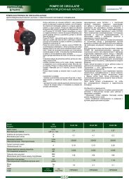
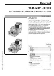
The <strong>A4021</strong> valve proving system checks the effective closure<br />
of the valves before burner start--up (pre--configuration) or at<br />
the end of a heat demand (post--configuration). The<br />
configuration can be set by means of wiring the <strong>A4021</strong> in two<br />
different ways, see Fig. 1. and 2.<br />
The flow chart (Fig. 4. ) and sequence diagram (Fig. 5. )<br />
explain the procedure during the valve proving.<br />
An external pressure switch monitors the pressure between<br />
both valves. The pressure switch must be set to half the inlet<br />
pressure in order to test both valves with the same sensitivity.<br />
After a short interruption of the mains supply during valve<br />
proving or during RUN, the <strong>A4021</strong> restarts automatically.<br />
The <strong>A4021</strong> valve proving system can be used with several<br />
pilot--valve configurations, like intermittent and interrupted<br />
pilot systems and 3--valve configurations as well.<br />
LGPS H.D<br />
L<br />
9<br />
<strong>A4021</strong><br />
14<br />
12<br />
Fig. 1. Valve proving pre--configuration.<br />
LGPS<br />
L<br />
9<br />
<strong>A4021</strong><br />
14<br />
12<br />
H.D<br />
Fig. 2. Valve proving post--configuration.<br />
ignition<br />
controller<br />
ignition<br />
controller<br />
heat<br />
demand<br />
Valve Proving System<br />
<strong>A4021</strong> <strong>Series</strong><br />
burner--controller<br />
7800 SERIES<br />
Gas pressure switches<br />
C6058A <strong>Series</strong><br />
L.G.P.S.<br />
G.P.S.<br />
Pinlet<br />
2<br />
gas<br />
Pinlet<br />
V1<br />
V2<br />
Combi--valve VQ400 <strong>Series</strong><br />
Servo Motor MT4000 <strong>Series</strong><br />
burner<br />
air<br />
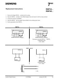
Fig. 3. System set--up .<br />
Working principle<br />
The <strong>A4021</strong> valve proving system is based on the pressure<br />
status--principle. This means that the valves are checked by<br />
means of measuring (on/off) the pressure in the gas--pipe<br />
between the two safety--valves. This system will only work<br />
when there is sufficient gas--pressure (line--pressure).<br />
Therefore a Low Gas Pressure Switch (LGPS) is part of the<br />
installation. When the line--pressure (Pinlet) is too low the<br />
LGPS will disable the valve proving system.<br />
The section between the two valves is filled with gas<br />
(high--pressure status) by opening valve--1 (upstream valve)<br />
and the pipe is emptied (low--pressure status) by closing<br />
valve--1 and opening valve--2 (down--stream). When one of<br />
the valves is leaking this will mean that either the pressure<br />
will not maintain the high--pressure status or the low--pressure<br />
status at the end of the test period.<br />
For this method of testing, the test time is a function of three<br />
parameters.<br />
− inlet pressure<br />
− volume between the valves.<br />
− maximum burner capacity.<br />
The test time can be calculated as given in the Product<br />
Handbook. Different test times are available by different O.S.<br />
numbers.<br />
EN2C-0030SZ20 R0604<br />
2