DTC P0106, P0107, P0108 4.13 - harley-davidson-sweden.se
DTC P0106, P0107, P0108 4.13 - harley-davidson-sweden.se
DTC P0106, P0107, P0108 4.13 - harley-davidson-sweden.se

You also want an ePaper? Increase the reach of your titles
YUMPU automatically turns print PDFs into web optimized ePapers that Google loves.
7<br />
HOME<br />
<strong>DTC</strong> <strong>P0106</strong>, <strong>P0107</strong>, <strong>P0108</strong> <strong>4.13</strong><br />
GENERAL<br />
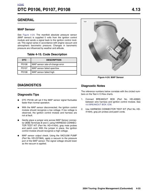
7351<br />
MAP Sensor<br />
See Figure 4-24. The manifold absolute pressure <strong>se</strong>nsor<br />
(MAP <strong>se</strong>nsor) is supplied 5 volts from the ignition control<br />
module and <strong>se</strong>nds a signal back to the ignition control module.<br />
This signal varies in accordance with engine vacuum and<br />
atmospheric barometric pressure. Changes in barometric<br />
pressure are influenced by weather and altitude.<br />
Table 4-15. Code Description<br />
<strong>DTC</strong><br />
<strong>P0106</strong><br />
<strong>P0107</strong><br />
<strong>P0108</strong><br />
DESCRIPTION<br />
MAP <strong>se</strong>nsor rate-of-change error<br />
MAP <strong>se</strong>nsor failed open/low<br />
MAP <strong>se</strong>nsor failed high<br />
Figure 4-24. MAP Sensor<br />
DIAGNOSTICS<br />
Diagnostic Tips<br />
Diagnostic Notes<br />
The reference numbers below correlate with the circled numbers<br />
on the Test <strong>4.13</strong> flow charts.<br />
●<br />
●<br />
●<br />
●<br />
<strong>DTC</strong> <strong>P0106</strong> will <strong>se</strong>t if the MAP <strong>se</strong>nsor signal fluctuates<br />
faster than normal operation.<br />
With the MAP <strong>se</strong>nsor disconnected, the ignition control<br />
module should recognize a low voltage. If low voltage is<br />
ob<strong>se</strong>rved, the ignition control module and harness are<br />
not at fault.<br />
Gently place a jumper wire across MAP Sensor connector<br />
[80B] Terminals B and C using HARNESS CONNEC-<br />
TOR TEST KIT (Part No. HD-41404), gray male probes<br />
and patch cord. With the jumper in place, the ignition<br />
control module should recognize a high voltage.<br />
MAP <strong>se</strong>nsor output check. Using the VACUUM PUMP<br />
(Part No. HD-23738A), apply a vacuum to the pressure<br />
port of the MAP <strong>se</strong>nsor. The signal voltage should lower<br />
as the vacuum is applied.<br />
1. Connect BREAKOUT BOX (Part No. HD-42682)<br />
between wire harness and ignition control module. See<br />
4.6 BREAKOUT BOX: ICM.<br />
2. U<strong>se</strong> HARNESS CONNECTOR TEST KIT (Part No. HD-<br />
41404), gray pin probes and patch cords.<br />
2004 Touring: Engine Management (Carbureted) 4-33
HOME<br />
s0587a8x<br />
Manifold<br />
absolute<br />
pressure<br />
<strong>se</strong>nsor<br />
(MAP)<br />
[80A]<br />
[80B]<br />
BK/W<br />
V/W<br />
R/W<br />
To vehicle<br />
speed <strong>se</strong>nsor<br />
(VSS)<br />
R/W<br />
BK/W<br />
V/W<br />
[10B]<br />
[10A]<br />
Sensor power<br />
Sensor ground<br />
MAP signal<br />
Ignition control module<br />
Figure 4-25. MAP Sensor Circuit<br />
Table 4-16. Wire Harness Connectors in Figure 4-25.<br />
NO. DESCRIPTION TYPE LOCATION<br />
[10] Ignition Control Module 12-Place Deutsch Under Right Side Cover<br />
[80] Manifold Absolute Pressure Sensor (MAP) 3 - Place Packard Top of Intake Manifold<br />
4-34 2004 Touring: Engine Management (Carbureted)
HOME<br />
Test <strong>4.13</strong> (Part 1 of 2)<br />
MAP SENSOR: <strong>DTC</strong> <strong>P0106</strong>, <strong>P0107</strong>, <strong>P0108</strong><br />
1<br />
With ignition ON, measure voltage<br />
between Breakout Box terminal 11 (+)<br />
and terminal 4 (-). With key ON,<br />
engine OFF, voltage must be between<br />
4.2 and 4.95 volts. With key ON,<br />
engine running, voltage must be<br />
between 1.5-3.0 volts at hot idle.<br />
Does voltage fit specifications<br />
YES<br />
NO<br />
Perform 4.7 WIGGLE TEST<br />
to check for intermittents.<br />
Intermittents pre<strong>se</strong>nt<br />
STOP<br />
Go to Test <strong>4.13</strong><br />
(Part 2 of 2).<br />
YES<br />
NO<br />
To identify the source of intermittents,<br />
start with box marked<br />
by Bold Asterisk under Test<br />
<strong>4.13</strong> (Part 2 of 2). Wiggle harness<br />
while watching DVOM.<br />
Replace MAP <strong>se</strong>nsor. See the Touring Service<br />
Manual. Clear diagnostic trouble codes.<br />
See 4.5 SPEEDOMETER SELF DIAGNOS-<br />
TICS. Road test. Did check engine lamp illuminate<br />
and <strong>se</strong>t Code <strong>P0106</strong>, <strong>P0107</strong> or<br />
YES<br />
NO<br />
Install original MAP <strong>se</strong>nsor.<br />
Replace ignition control module<br />
and road test again to verify.<br />
System<br />
now OK.<br />
Clear codes using speedometer <strong>se</strong>lf diagnostics.<br />
See 4.5 SPEEDOMETER SELF DIAGNOSTICS.<br />
Confirm proper operation with no check engine<br />
lamp.<br />
At some point in the flow chart you<br />
may be instructed to jump directly<br />
to a the box with the bold asterisk.<br />
Disregard the asterisk (but not the<br />
instruction box) if your normal progression<br />
through the chart brings<br />
you to this location.<br />
2004 Touring: Engine Management (Carbureted) 4-35
HOME<br />
Test <strong>4.13</strong> (Part 2 of 2)<br />
MAP SENSOR: <strong>DTC</strong> <strong>P0106</strong>, <strong>P0107</strong>, <strong>P0108</strong><br />
2<br />
Continued from Test <strong>4.13</strong> (Part 1 of 2).<br />
Check the 5 volt reference supply at<br />
the MAP <strong>se</strong>nsor connector [80B]. With<br />
ignition ON, measure voltage between<br />
terminal C (R/W) and terminal A (BK/W).<br />
Is voltage approximately 5.0 volts<br />
YES<br />
NO.<br />
Greater<br />
than 6V.<br />
NO.<br />
Less<br />
than 4.5V.<br />
1<br />
2<br />
Connect Breakout Box. Disconnect ignition<br />
control module from Breakout Box.<br />
OPEN CHECK: Measure resistance<br />
between MAP connector [80B] Terminal B<br />
and Breakout Box connector [10]<br />
terminal 11. Is resistance less than 1 ohm<br />
YES<br />
Locate short to 12 volts on R/W<br />
wire in wire harness. Repair as<br />
necessary.<br />
NO<br />
1<br />
2<br />
Disconnect ignition control module from<br />
Breakout Box.<br />
Check continuity between MAP connector<br />
[80B] Terminal C and Breakout Box<br />
connector [10] terminal 3. Then measure<br />
continuity between MAP connector [80B]<br />
Terminal A and Breakout Box connector [10]<br />
terminal 4.<br />
Continuity pre<strong>se</strong>nt<br />
2<br />
SHORT CHECK: Measure<br />
resistance between MAP connector<br />
Terminal B and chassis<br />
ground. Is resistance greater<br />
than 1 meg ohm<br />
Locate and repair<br />
open on V/W wire.<br />
YES<br />
NO<br />
YES<br />
NO<br />
With MAP <strong>se</strong>nsor connector<br />
[80] disconnected, check<br />
resistance between Breakout<br />
Box terminal 3 and 5<br />
(black). Is it greater than 1<br />
megohm<br />
Repair<br />
open wire.<br />
Replace MAP <strong>se</strong>nsor. See the<br />
Touring Service Manual.<br />
Locate and repair<br />
grounded V/W wire.<br />
YES<br />
NO<br />
Replace ICM.<br />
Reprogram and<br />
learn password.<br />
Locate and repair<br />
short between<br />
R/W wire and<br />
ground.<br />
Clear codes using speedometer <strong>se</strong>lf diagnostics.<br />
See 4.5 SPEEDOMETER SELF DIAGNOSTICS.<br />
Confirm proper operation with no check engine<br />
lamp.<br />
At some point in the flow chart you<br />
may be instructed to jump directly<br />
to a the box with the bold asterisk.<br />
Disregard the asterisk (but not the<br />
instruction box) if your normal progression<br />
through the chart brings<br />
you to this location.<br />
4-36 2004 Touring: Engine Management (Carbureted)
HOME<br />
<strong>DTC</strong> P0562, P0563 4.14<br />
GENERAL<br />
DIAGNOSTICS<br />
Battery Voltage<br />
The ignition control module monitors battery positive voltage.<br />
The normal operating range is between 8-16 volts while<br />
engine is running.<br />
NOTE<br />
When either a diagnostic trouble code P0562 or P0563 is <strong>se</strong>t,<br />
the battery icon in the speedometer will illuminate.<br />
●<br />
●<br />
●<br />
●<br />
A <strong>DTC</strong> P0562 is <strong>se</strong>t if the ignition module detects battery<br />
positive voltage less than 8 volts while the engine is running.<br />
A <strong>DTC</strong> P0563 is <strong>se</strong>t if the ignition module detects battery<br />
positive voltage greater than 16 volts.<br />
Low voltage generally indicates a loo<strong>se</strong> wire, corroded<br />
connections and/or a charging system problem.<br />
A high voltage condition may be cau<strong>se</strong>d by a faulty voltage<br />
regulator.<br />
<strong>DTC</strong><br />
P0562<br />
P0563<br />
Table 4-17. Code Description<br />
battery voltage low<br />
battery voltage high<br />
DESCRIPTION<br />
Diagnostic Notes<br />
The reference numbers below correlate with the circled numbers<br />
on the Test 4.14 flow charts.<br />
1. Was battery allowed to discharge Was battery drawn<br />
down by a starting problem<br />
a. Yes. Charge battery.<br />
b. No. See charging system troubleshooting.<br />
2. Connect BREAKOUT BOX (Part No. HD-42682)<br />
between wire harness and ignition control module. See<br />
4.6 BREAKOUT BOX: ICM.<br />
3. The ignition control module is monitoring voltage at ignition<br />
control module connector [10] (black) Pin 1.<br />
4. This checks for voltage drops in the ignition control module<br />
circuit.<br />
a. Place (+) probe to battery positive terminal.<br />
b. Place (-) probe to terminal 1 on Breakout Box.<br />
5. Remove Breakout Box at ICM, reconnect ICM. In<strong>se</strong>rt<br />
Breakout Box at connector [22] (BK). On FLHR/S models<br />
(6-place connector), install Breakout Box adapters (HD-<br />
42962).<br />
2004 Touring: Engine Management (Carbureted) 4-37
HOME<br />
R/BK To Ignition Switch<br />
[83B]<br />
Ignition Control Module<br />
15 Amp<br />
Ignition Fu<strong>se</strong><br />
GY<br />
A<br />
B<br />
C<br />
Ignition<br />
Coil<br />
W<br />
\<br />
B<br />
K<br />
Y \ BE<br />
BE \ O<br />
BK<br />
7<br />
6<br />
5<br />
Rear Coil<br />
Front Coil<br />
Ground<br />
W \ BK<br />
1<br />
Key ON Power<br />
To TSM/TSSM<br />
[10B] [10A]<br />
1 2 3 4 5 6 7 8 9 10 11 12<br />
[8A]<br />
[8B]<br />
To<br />
Data Link<br />
[1B]<br />
[1A]<br />
GY<br />
1 2 3 4 5 6 7 8 9 10 11 12<br />
FLHT/C Only<br />
Ground Stud<br />
Engine Stop Switch<br />
W \ BK<br />
[22B]<br />
[22A]<br />
6-Place on FLHR/S<br />
1 2 3 4 5 6 7 8 9 10 11 12<br />
Figure 4-26. Battery Voltage Circuit<br />
Table 4-18. Wire Harness Connectors in Figure 4-26.<br />
NO. DESCRIPTION MODEL TYPE LOCATION<br />
[1] Main to Interconnect Harness FLHT/C 12-Place Deutsch Inner Fairing- Right Fairing Bracket<br />
[8] Ignition Harness All 12-Place Deutsch Under Right Side Cover<br />
[10] Ignition Control Module All 12-Place Deutsch (Black) Under Right Side Cover<br />
[22]<br />
Interconnect to Right<br />
Handlebar Switch Controls<br />
FLHT/C 12-Place Deutsch<br />
Inner Fairing-<br />
Right Fairing Support Brace<br />
FLHR/S 6-Place Deutsch Inside Headlamp Nacelle<br />
[83] Ignition Coil All 3 - Place Packard Below Fuel Tank (Left Side)<br />
4-38 2004 Touring: Engine Management (Carbureted)
HOME<br />
Test 4.14 (Part 1 of 2)<br />
BATTERY VOLTAGE: <strong>DTC</strong> P0562, P0563<br />
1<br />
Perform charging system tests.<br />
Charging system OK<br />
YES<br />
NO<br />
2<br />
3<br />
4<br />
With ignition ON, measure voltage drop<br />
between battery positive (+) terminal<br />
and Breakout Box connector [10] (black)<br />
Pin 1 (-). Is voltage drop greater<br />
than 0.5 volt<br />
Repair<br />
charging system.<br />
YES<br />
NO<br />
5<br />
With ignition ON, measure voltage drop<br />
between battery positive (+) terminal<br />
and connector [22A] Pin 4 (-). Is voltage<br />
drop greater than 0.5 volt<br />
Check for voltage drop between battery<br />
negative (-) terminal and Pin 5 (+) on<br />
connector [10B] (black) on Breakout Box.<br />
Is voltage drop greater than 0.5 volt<br />
YES<br />
NO<br />
YES<br />
NO<br />
With ignition ON, measure voltage drop<br />
between battery positive (+) terminal<br />
and connector [22A] Pin 3 (-). Is voltage<br />
drop greater than 0.5 volt<br />
Repair or replace<br />
W/BK wire or<br />
terminals.<br />
Locate and repair<br />
bad connection.<br />
Problem is intermittent.<br />
Perform 4.7 WIGGLE<br />
TEST.<br />
YES<br />
NO<br />
STOP<br />
Go to Test 4.14<br />
(Part 2 of 2).<br />
Inspect connector [22] for<br />
corrosion or loo<strong>se</strong> wires. If<br />
above conditions are not<br />
pre<strong>se</strong>nt, replace engine stop<br />
switch.<br />
Clear codes using speedometer <strong>se</strong>lf diagnostics.<br />
See 4.5 SPEEDOMETER SELF DIAGNOSTICS.<br />
Confirm proper operation with no check engine<br />
lamp.<br />
2004 Touring: Engine Management (Carbureted) 4-39
HOME<br />
Test 4.14 (Part 2 of 2)<br />
BATTERY VOLTAGE: <strong>DTC</strong> P0562, P0563<br />
Continued from Test 4.14 (Part 1 of 2). With<br />
ignition ON, measure voltage drop between<br />
battery positive (+) terminal and GY terminal<br />
on 15 amp ignition fu<strong>se</strong> (-). Is voltage<br />
drop greater than 0.5 volt<br />
YES<br />
NO<br />
With ignition ON, measure voltage drop<br />
between battery positive (+) terminal and<br />
R/BK terminal on 15 amp ignition fu<strong>se</strong>. Is<br />
voltage drop greater than 0.5 volt<br />
Repair or replace GY<br />
wire or terminals.<br />
YES<br />
NO<br />
With ignition ON, measure voltage drop<br />
between battery positive (+) terminal and<br />
terminal A of maxi fu<strong>se</strong> (-).<br />
Is voltage drop greater than 0.5 volt<br />
Replace fu<strong>se</strong> or<br />
fu<strong>se</strong> terminals.<br />
YES<br />
NO<br />
With ignition ON, measure voltage drop<br />
between battery positive (+) terminal and<br />
terminal B of maxi fu<strong>se</strong> (-).<br />
Is voltage drop greater than 0.5 volt<br />
Replace ignition<br />
switch or terminals.<br />
YES<br />
NO<br />
High resistance between maxi<br />
fu<strong>se</strong> and battery. Replace wire or<br />
terminals.<br />
Replace maxi fu<strong>se</strong>.<br />
Clear codes using speedometer <strong>se</strong>lf diagnostics.<br />
See 4.5 SPEEDOMETER SELF DIAGNOSTICS.<br />
Confirm proper operation with no check engine<br />
lamp.<br />
4-40 2004 Touring: Engine Management (Carbureted)
HOME<br />
<strong>DTC</strong> P1009, P1010 4.15<br />
GENERAL<br />
Password Problem<br />
The ICM and TSM/TSSM exchange passwords during operation.<br />
An incorrect password or missing password will <strong>se</strong>t a<br />
diagnostic code.<br />
NOTE<br />
If the TSM/TSSM is not connected to the wiring harness, the<br />
vehicle will not start.<br />
Table 4-19. Code Description<br />
<strong>DTC</strong><br />
DESCRIPTION<br />
P1009 Incorrect password<br />
P1010 Missing password Figure 4-27. TSM/TSSM<br />
DIAGNOSTICS<br />
6924<br />
Diagnostic Notes<br />
The reference numbers below correlate with the circled numbers<br />
on the Test 4.15 flow charts.<br />
1. <strong>DTC</strong> P1009 may be <strong>se</strong>t if a recent ICM or TSM/TSSM<br />
replacement did not follow the correct password assignment<br />
procedure. See 3.24 PASSWORD LEARN for<br />
details.<br />
2. U<strong>se</strong> HARNESS CONNECTOR TEST KIT (Part No. HD-<br />
41404), black socket probes and patch cord.<br />
3. Connect BREAKOUT BOX (Part No. HD-42682)<br />
between wire harness and ICM. See 4.6 BREAKOUT<br />
BOX: ICM.<br />
4. See the Touring Service Manual for TSM/TSSM replacement.<br />
See PASSWORD LEARNING under 3.24 PASS-<br />
WORD LEARN for the password learning procedure.<br />
3<br />
2<br />
1. Terminal 2: ground (BK)<br />
2. Terminal 3: <strong>se</strong>rial data (Lt GN/V)<br />
3. Terminal 4: power (GY)<br />
4. Protective cap<br />
Figure 4-28. Data Link Connector<br />
1<br />
4<br />
2004 Touring: Engine Management (Carbureted) 4-41
HOME<br />
f2208z8x<br />
BK<br />
LtGN/V<br />
O<br />
BN/GY<br />
[156B] [156A]<br />
6<br />
5<br />
4<br />
3<br />
2<br />
1<br />
BN/GY<br />
6<br />
5<br />
4<br />
3<br />
2<br />
1<br />
Main to Interconnect<br />
Harness<br />
LtGN/V<br />
GY<br />
1 2 3 4 5 6 7 8 9 10 11 12<br />
1 2 3 4 5 6 7 8 9 10 11 12<br />
TSM/TSSM<br />
BK<br />
[30B]<br />
[30A]<br />
1 2 3 4 5 6 7 8 9 10 11 12<br />
1 2 3 4 5 6 7 8 9 10 11 12<br />
Speedometer<br />
[39B]<br />
[39A]<br />
[108B]<br />
[108A]<br />
1 2 3 4 5 6 7 8 9 10 11 12<br />
1 2 3 4 5 6 7 8 9 10 11 12<br />
Tachometer<br />
GY<br />
1 2 3 4 5 6 7 8 9 10 11 12<br />
1 2 3 4 5 6 7 8 9 10 11 12<br />
[8B]<br />
[8A]<br />
BK<br />
Ignition<br />
Harness<br />
[2A]<br />
[2B]<br />
15A<br />
Accessory<br />
Fu<strong>se</strong><br />
1 2 3 4 5 6 7 8 9 10 11 12<br />
1 2 3 4 5 6 7 8 9 10 11 12<br />
Main to Interconnect<br />
Harness<br />
[1B] [1A]<br />
12 11 10 9 8 7 6 5 4 3 2 1<br />
12 11 10 9 8 7 6 5 4 3 2 1<br />
Main to Interconnect<br />
Harness<br />
15A<br />
Ignition<br />
Fu<strong>se</strong><br />
LtGN/V<br />
1<br />
2<br />
3<br />
4<br />
[91A]<br />
Data Link<br />
15A<br />
Battery<br />
Fu<strong>se</strong><br />
[10B]<br />
[10A]<br />
Ignition Control Module<br />
12<br />
12<br />
Serial data<br />
Figure 4-29. Serial Data Circuit (FLHT/C)<br />
Table 4-20. Wire Harness Connectors in Figure 4-29.<br />
NO. DESCRIPTION TYPE LOCATION<br />
[1] Main to Interconnect Harness 12-Place Deutsch (Black) Inner Fairing - Right Radio Support Bracket<br />
[2] Main to Interconnect Harness 12-Place Deutsch (Gray) Inner Fairing - Right Fairing Support Brace<br />
[8] Ignition Harness 12-Place Deutsch Under Right Side Cover<br />
[10] Ignition Control Module 12-Place Deutsch Under Right Side Cover<br />
[30] Turn Signal/Security Module 12-Place Deutsch<br />
Cavity in Crossmember at Rear of<br />
Battery Box (Under Seat)<br />
[39] Speedometer 12-Place Packard Inner Fairing (Back of Speedometer)<br />
[91] Data Link 4-Place Deutsch Under Right Side Cover<br />
[108] Tachometer 12-Place Packard Inner Fairing (Back of Tachometer)<br />
[156] Main to Interconnect Harness 6-Place Deutsch Inner Fairing - Right Fairing Support Brace<br />
4-42 2004 Touring: Engine Management (Carbureted)
HOME<br />
f2208y8x<br />
BK<br />
GY<br />
LtGN/V<br />
LtGN/V<br />
BK<br />
BN/GY<br />
BN/GY<br />
O<br />
1 2 3 4 5 6 7 8 9 10 11 12<br />
1 2 3 4 5 6 7 8 9 10 11 12<br />
TSM/TSSM<br />
[30B]<br />
[30A]<br />
1 2 3 4 5 6 7 8 9 10 11 12<br />
1 2 3 4 5 6 7 8 9 10 11 12<br />
Speedometer<br />
[39B]<br />
[39A]<br />
GY<br />
1 2 3 4 5 6 7 8 9 10 11 12<br />
1 2 3 4 5 6 7 8 9 10 11 12<br />
BK<br />
[8B]<br />
[8A]<br />
Ignition<br />
Harness<br />
15A<br />
Battery<br />
Fu<strong>se</strong><br />
15A<br />
Accessory<br />
Fu<strong>se</strong><br />
1<br />
2<br />
3<br />
4<br />
[91A]<br />
Data Link<br />
15A<br />
Ignition<br />
Fu<strong>se</strong><br />
LtGN/V<br />
[10B]<br />
[10A]<br />
Ignition Control Module<br />
12<br />
12<br />
Serial data<br />
Figure 4-30. Serial Data Circuit (FLHR/S)<br />
Table 4-21. Wire Harness Connectors in Figure 4-30.<br />
NO. DESCRIPTION TYPE LOCATION<br />
[8] Ignition Harness 12-Place Deutsch Under Right Side Cover<br />
[10] Ignition Control Module 12-Place Deutsch Under Right Side Cover<br />
[30] Turn Signal/Security Module 12-Place Deutsch<br />
Cavity in Crossmember at Rear of<br />
Battery Box (Under Seat)<br />
[39] Speedometer 12-Place Packard Under Console (Back of Speedometer)<br />
[91] Data Link 4-Place Deutsch Under Right Side Cover<br />
2004 Touring: Engine Management (Carbureted) 4-43
HOME<br />
Test 4.15<br />
PASSWORD PROBLEM: <strong>DTC</strong> P1009, P1010<br />
Which diagnostic trouble<br />
code was <strong>se</strong>t<br />
1<br />
4<br />
<strong>DTC</strong> P1009.<br />
Bad password.<br />
Reprogram password.<br />
See 3.24 PASSWORD<br />
LEARN.<br />
<strong>DTC</strong> P1009 still exist<br />
<strong>DTC</strong> P1010.<br />
No password.<br />
Are there any<br />
U-codes <strong>se</strong>t<br />
YES<br />
NO<br />
YES<br />
NO<br />
4<br />
Replace TSSM and<br />
relearn password.<br />
System OK<br />
System<br />
OK.<br />
6701<br />
Troubleshoot<br />
lowest U-code.<br />
Remove ICM connector [10]. Check<br />
for continuity to ground at data<br />
connector [91A] Terminal 3.<br />
Continuity pre<strong>se</strong>nt<br />
2<br />
YES<br />
NO<br />
YES<br />
NO<br />
System<br />
OK.<br />
6702<br />
5<br />
Reinstall original TSSM.<br />
Replace ICM.<br />
Reprogram and relearn<br />
password.<br />
Repair short<br />
to ground.<br />
6704<br />
Check for battery voltage on Pin 3.<br />
Battery voltage pre<strong>se</strong>nt<br />
6703<br />
YES<br />
NO<br />
Repair short<br />
to voltage.<br />
6705<br />
Test data connector [91A]<br />
Terminal 3 against Breakout Box Pin<br />
12 for continuity. Continuity pre<strong>se</strong>nt<br />
2<br />
3<br />
YES<br />
NO<br />
4<br />
Replace TSM/TSSM and relearn<br />
password. System OK<br />
2<br />
Inspect terminals<br />
for damage or repair<br />
opens as necessary.<br />
6706<br />
YES<br />
NO<br />
System<br />
OK.<br />
6707<br />
4<br />
Reinstall original TSSM.<br />
Replace ICM.<br />
Reprogram and relearn<br />
password.<br />
6708<br />
Clear codes using speedometer <strong>se</strong>lf diagnostics.<br />
See 4.5 SPEEDOMETER SELF DIAGNOSTICS.<br />
Confirm proper operation with no check engine<br />
lamp.<br />
4-44 2004 Touring: Engine Management (Carbureted)
HOME<br />
<strong>DTC</strong> P1351, P1352, P1354, P1355 4.16<br />
GENERAL<br />
7863<br />
Ignition Coil<br />
Ignition coil codes will <strong>se</strong>t if the ignition coil primary voltage is<br />
out of range. This could occur if there is an open coil or loss of<br />
power to the coil. If front and rear codes are <strong>se</strong>t simultaneously,<br />
it is likely a coil power failure or a coil failure.<br />
The coil receives power from the engine run/stop switch. The<br />
ignition control module is responsible for turning on the coils<br />
by providing the ground to activate the coils, which in turn<br />
powers the coils.<br />
Table 4-22. Code Description<br />
<strong>DTC</strong><br />
DESCRIPTION<br />
Figure 4-31. Ignition Coil Circuit Test<br />
P1351<br />
P1352<br />
Front ignition coil open/low<br />
Front ignition coil high/shorted<br />
s0592x8x<br />
Coil tower<br />
P1354<br />
Rear ignition coil open/low<br />
P1355<br />
Rear ignition coil high/shorted<br />
DIAGNOSTICS<br />
Diagnostic Notes<br />
The reference numbers below correlate with the circled numbers<br />
on the Test 4.16 flow charts.<br />
1. U<strong>se</strong> HARNESS CONNECTOR TEST KIT (Part No. HD-<br />
41404), gray pin probes and patch cord.<br />
C<br />
B<br />
A<br />
CAUTION<br />
Gently connect test lamp to connector [83B]. Forcefully<br />
in<strong>se</strong>rting test lamp will result in ignition connector terminal<br />
damage.<br />
2. See Figure 4-31. Plug IGNITION COIL CIRCUIT TEST<br />
ADAPTER (Part No. HD-44687) and FUEL INJECTOR<br />
TEST LAMP (Part No. HD-34730-2C) into Breakout Box.<br />
Note that cranking the engine with test lamp in place of<br />
the ignition coil can sometimes cau<strong>se</strong> a <strong>DTC</strong> P1351,<br />
P1352, P1354 or P1355. This condition is normal and<br />
does not by it<strong>se</strong>lf indicate a malfunction. Codes must be<br />
cleared if this condition occurs.<br />
3. Connect BREAKOUT BOX (Part No. HD-42682)<br />
between wire harness and ICM. See 4.6 BREAKOUT<br />
BOX: ICM.<br />
Figure 4-32. Ignition Coil Connector Terminals<br />
4. U<strong>se</strong> HARNESS CONNECTOR TEST KIT (Part No. HD-<br />
41404), gray socket probes and patch cord.<br />
Table 4-23. Coil Terminal Description<br />
TERMINAL DESCRIPTION WIRE COLOR<br />
A Rear coil Y/BE<br />
B Power W/BK<br />
C Front coil BE/O<br />
2004 Touring: Engine Management (Carbureted) 4-45
HOME<br />
R/BK To Ignition Switch<br />
[83B]<br />
Ignition Control Module<br />
15 Amp<br />
Ignition Fu<strong>se</strong><br />
GY<br />
A<br />
B<br />
C<br />
Ignition<br />
Coil<br />
W<br />
\<br />
B<br />
K<br />
Y \ BE<br />
BE \ O<br />
BK<br />
7<br />
6<br />
5<br />
Rear Coil<br />
Front Coil<br />
Ground<br />
W \ BK<br />
1<br />
Key ON Power<br />
To TSM/TSSM<br />
[10B] [10A]<br />
1 2 3 4 5 6 7 8 9 10 11 12<br />
[8A]<br />
[8B]<br />
To<br />
Data Link<br />
[1B]<br />
[1A]<br />
GY<br />
1 2 3 4 5 6 7 8 9 10 11 12<br />
FLHT/C Only<br />
Ground Stud<br />
Engine Stop Switch<br />
W \ BK<br />
[22B]<br />
[22A]<br />
6-Place on FLHR/S<br />
1 2 3 4 5 6 7 8 9 10 11 12<br />
Figure 4-33. Battery Voltage Circuit<br />
Table 4-24. Wire Harness Connectors in Figure 4-33.<br />
NO. DESCRIPTION MODEL TYPE LOCATION<br />
[1] Main to Interconnect Harness FLHT/C 12-Place Deutsch Inner Fairing- Right Fairing Bracket<br />
[8] Ignition Harness All 12-Place Deutsch Under Right Side Cover<br />
[10] Ignition Control Module All 12-Place Deutsch (Black) Under Right Side Cover<br />
[22]<br />
Interconnect to Right<br />
Handlebar Switch Controls<br />
FLHT/C 12-Place Deutsch<br />
Inner Fairing-<br />
Right Fairing Support Brace<br />
FLHR/S 6-Place Deutsch Inside Headlamp Nacelle<br />
[83] Ignition Coil All 3 - Place Packard Below Fuel Tank (Left Side)<br />
4-46 2004 Touring: Engine Management (Carbureted)
HOME<br />
Test 4.16 (Part 1 of 2)<br />
IGNITION COIL: <strong>DTC</strong> P1351, P1352, P1354, P1355<br />
1<br />
Disconnect connector [83].<br />
Measure voltage on Terminal B<br />
of coil. Equal to battery voltage<br />
after key ON<br />
2<br />
3<br />
YES<br />
U<strong>se</strong> Breakout Box and test light for the<br />
next inspection.<br />
Front coil codes: Check between ICM Pin<br />
6 and ICM Pin 1.<br />
Rear coil codes: Check between ICM Pin<br />
7 and ICM Pin 1.<br />
Does test lamp flash when engine is<br />
cranked<br />
NO<br />
Repair open wire or<br />
connection on W/BK wire.<br />
YES<br />
NO<br />
Measure coil resistance.<br />
Replace ICM.<br />
4<br />
Reprogram and<br />
Front coil codes: Check between<br />
perform password learn.<br />
coil Terminal B and Terminal C.<br />
Rear coil codes: Check between<br />
coil Terminal B and Terminal A.<br />
Resistance 0.5-0.7 ohms<br />
YES<br />
NO<br />
STOP<br />
Replace coil.<br />
Go to Test 4.16<br />
(Part 2 of 2).<br />
Clear codes using speedometer <strong>se</strong>lf diagnostics.<br />
See 4.5 SPEEDOMETER SELF DIAGNOSTICS.<br />
Confirm proper operation with no check engine<br />
lamp.<br />
2004 Touring: Engine Management (Carbureted) 4-47
HOME<br />
Test 4.16 (Part 2 of 2)<br />
IGNITION COIL: <strong>DTC</strong> P1351, P1352, P1354, P1355<br />
Continued from Test 4.16 (Part 1 of 2).<br />
Using Breakout Box, measure resistance between<br />
ICM and coil terminals as follows.<br />
<strong>DTC</strong><br />
COIL<br />
TERMINAL<br />
BREAK-<br />
OUT BOX<br />
TERMINAL<br />
P1351/<br />
P1352<br />
C<br />
(BE/O wire)<br />
6<br />
1<br />
P1353/<br />
P1354<br />
A<br />
(Y/BE wire)<br />
7<br />
3<br />
Resistance less than 0.5 ohms<br />
YES<br />
NO<br />
Perform 5.8 WIGGLE TEST<br />
to check for intermittents.<br />
Intermittents pre<strong>se</strong>nt<br />
Repair open wire<br />
or connection.<br />
YES<br />
NO<br />
Repair<br />
intermittent.<br />
Check for continuity to ground.<br />
Front coil codes: Check<br />
Breakout Box Pin 6.<br />
Rear coil codes: Check<br />
Breakout Box Pin 7.<br />
Continuity pre<strong>se</strong>nt<br />
YES<br />
NO<br />
Repair short<br />
to ground.<br />
Check for voltage.<br />
Front coil codes: Check<br />
Breakout Box Pin 6.<br />
Rear coil codes: Check<br />
Breakout Box Pin 7.<br />
Voltage pre<strong>se</strong>nt<br />
YES<br />
NO<br />
Repair short<br />
to voltage.<br />
Replace ICM.<br />
Reprogram and<br />
learn password.<br />
Clear codes using speedometer <strong>se</strong>lf diagnostics.<br />
See 4.5 SPEEDOMETER SELF DIAGNOSTICS.<br />
Confirm proper operation with no check engine<br />
lamp.<br />
4-48 2004 Touring: Engine Management (Carbureted)
HOME<br />
<strong>DTC</strong> P0373, P0374 4.17<br />
GENERAL<br />
Crank Position Sensor<br />
f2256x8x<br />
See Figure 4-34. A <strong>DTC</strong> P0373, P0374 will <strong>se</strong>t if the crankshaft<br />
position <strong>se</strong>nsor (CKP) signal is weak or ab<strong>se</strong>nt.<br />
Table 4-25. Code Description<br />
<strong>DTC</strong><br />
P0373<br />
P0374<br />
DESCRIPTION<br />
Crankshaft position <strong>se</strong>nsor intermittent<br />
Crankshaft position <strong>se</strong>nsor not detected or<br />
cannot synchronize<br />
Stator<br />
Connector [46]<br />
DIAGNOSTICS<br />
Diagnostic Notes<br />
1. Connect BREAKOUT BOX (Part No. HD-42682) to ignition<br />
control module wire harness only, leaving ignition<br />
control module disconnected. See 4.6 BREAKOUT BOX:<br />
ICM.<br />
Crankshaft<br />
Position Sensor<br />
Connector [79]<br />
Under Voltage Regulator<br />
Figure 4-34. Voltage Regulator (Left Side View)<br />
2. One megohm is very high resistance. Some meters will<br />
read infinity, OL, etc.<br />
3. U<strong>se</strong> HARNESS CONNECTOR TEST KIT (Part No. D-<br />
41404), brown socket probes and patch cords.<br />
4. For testing purpo<strong>se</strong>s, install <strong>se</strong>nsor without running wiring<br />
along normal path. Disconnect and route wiring properly<br />
if system is now OK.<br />
2004 Touring: Engine Management (Carbureted) 4-49
HOME<br />
Crankshaft<br />
Position<br />
Sensor<br />
f2208w8x<br />
[79A]<br />
[79B]<br />
1 2<br />
[10B]<br />
[10A]<br />
Module Ground<br />
Crank Sensor (+)<br />
Crank Sensor (-)<br />
BK<br />
R<br />
BK<br />
R<br />
BK<br />
Ignition Control Module<br />
Figure 4-35. Ignition Circuit<br />
Table 4-26. Wire Harness Connectors in Figure 4-35.<br />
NO. DESCRIPTION TYPE LOCATION<br />
[10] Ignition Control Module 12-Place Deutsch Under Right Side Cover<br />
[79] Crankshaft Position Sensor 2 - Place Mini-Deutsch Bottom of Voltage Regulator<br />
4-50 2004 Touring: Engine Management (Carbureted)
HOME<br />
Test 4.17<br />
CRANK POSITION SENSOR: <strong>DTC</strong> P0373, P0374<br />
1<br />
2<br />
Leaving ICM disconnected, connect Breakout<br />
Box to harness only. Measure resistance<br />
between Pins 8 and 5, and between Pins 9 and 5<br />
on connector [10]. Is resistance more than 1<br />
megohm<br />
YES<br />
Check for intermittent connection, pinched<br />
or damaged wires, and loo<strong>se</strong> CKP <strong>se</strong>nsor<br />
fastener. Conditions found<br />
NO<br />
Disconnect connector [79]. Leaving ICM<br />
disconnected, u<strong>se</strong> Breakout Box to measure<br />
resistance between Pins 8 and 5 on connector<br />
[10]. Also measure resistance between Pins 9<br />
and 5 on connector [10]. Is there still continuity to<br />
ground (less than 1 megohm resistance)<br />
YES<br />
NO<br />
Repair as<br />
necessary.<br />
Connect DVOM to Terminals 8 and 9 at<br />
connector [10] on Breakout Box.<br />
Set DVOM to AC volts and crank engine.<br />
Does DVOM read 1 VAC minimum<br />
during cranking<br />
YES<br />
Repair short to<br />
ground on R or<br />
BK wire between<br />
connectors [10B]<br />
and [79B].<br />
NO<br />
Replace CKP<br />
<strong>se</strong>nsor.<br />
YES<br />
NO<br />
With DVOM still connected, check for<br />
intermittents using 4.7 WIGGLE TEST.<br />
Intermittents pre<strong>se</strong>nt<br />
3<br />
Connect DVOM at Terminals 1<br />
and 2 of connector [79A].<br />
DVOM should read 1 VAC<br />
minimum while cranking.<br />
Does it<br />
YES<br />
NO<br />
Repair as<br />
necessary.<br />
Replace CKP<br />
<strong>se</strong>nsor. Clear<br />
codes and retest.<br />
Code P0373,<br />
P0374 <strong>se</strong>t<br />
YES<br />
Check for continuity between<br />
Pin 8 [10B] and Pin 1 [79B]. Is<br />
continuity pre<strong>se</strong>nt<br />
NO<br />
Replace CKP<br />
<strong>se</strong>nsor.<br />
4<br />
YES<br />
NO<br />
YES<br />
NO<br />
Reinstall CKP<br />
<strong>se</strong>nsor. Replace<br />
ICM. Reprogram<br />
and perform password<br />
learn.<br />
System<br />
OK.<br />
Repair open on BK wire<br />
between Pin 2 [79B] and Pin 9<br />
on connector [10B].<br />
Repair open on R wire<br />
between Pin 1 [79B] and Pin 8<br />
on connector [10B].<br />
Clear codes using speedometer <strong>se</strong>lf diagnostics.<br />
See 4.5 SPEEDOMETER SELF DIAGNOSTICS.<br />
Confirm proper operation with no check engine<br />
lamp.<br />
2004 Touring: Engine Management (Carbureted) 4-51
HOME<br />
<strong>DTC</strong> P0501, P0502 4.18<br />
GENERAL<br />
7951<br />
Vehicle Speed Sensor<br />
See Figure 4-36. The vehicle speed <strong>se</strong>nsor is powered and<br />
monitored by the ICM. The ICM proces<strong>se</strong>s the vehicle speed<br />
signal and transmits this signal to the TSM/TSSM and speedometer<br />
through <strong>se</strong>rial data.<br />
Speed<br />
Sensor<br />
NOTE<br />
When the vehicle speed signal is greater than 0, the clo<strong>se</strong>d<br />
loop idle speed control is inhibited.<br />
Table 4-27. Code Description<br />
<strong>DTC</strong><br />
P0501<br />
P0502<br />
DESCRIPTION<br />
VSS <strong>se</strong>nsor low<br />
VSS <strong>se</strong>nsor high/open<br />
Engine Oil Fill<br />
Plug/Dipstick<br />
DIAGNOSTICS<br />
Figure 4-36. Vehicle Speed Sensor Location<br />
f2183x8x<br />
Diagnostic Notes<br />
The reference numbers below correlate with the circled numbers<br />
on the Test 4.18 flow charts.<br />
1. The speedometer has a built-in diagnostic mode. See<br />
4.5 SPEEDOMETER SELF DIAGNOSTICS.<br />
1<br />
2. U<strong>se</strong> HARNESS CONNECTOR TEST KIT (Part No. HD-<br />
41404), black pin probe and patch cord.<br />
3. Connect BREAKOUT BOX (Part No. HD-42682)<br />
between wire harness and ICM. See 4.6 BREAKOUT<br />
BOX: ICM.<br />
4. Jack up motorcycle and rotate rear wheel with transmission<br />
in neutral.<br />
2<br />
1. Vehicle Speed Sensor Connector [65]<br />
2. P&A Security Siren Connector [142]<br />
Figure 4-37. Electrical Bracket (Inboard Side)<br />
4-52 2004 Touring: Engine Management (Carbureted)
HOME<br />
Vehicle Speed<br />
Sensor<br />
f2208x8x<br />
R<br />
W<br />
BK<br />
A<br />
B<br />
C<br />
A<br />
B<br />
C<br />
R/W<br />
W/GN<br />
BK/W<br />
[65A]<br />
[65B]<br />
R/W<br />
BK/W<br />
W/GN<br />
[10B]<br />
[10A]<br />
3<br />
10<br />
Ignition<br />
Control<br />
Module<br />
5v Power<br />
Sensor Ground<br />
VSS<br />
Figure 4-38. Vehicle Speed Sensor Circuit<br />
Table 4-28. Wire Harness Connectors in Figure 4-38.<br />
NO. DESCRIPTION TYPE LOCATION<br />
[10] Ignition Control Module 12-Place Deutsch Under Right Side Cover<br />
[65] Vehicle Speed Sensor 3 - Place Deutsch Under Right Side Cover (Behind Electrical Bracket)<br />
2004 Touring: Engine Management (Carbureted) 4-53
HOME<br />
Test 4.18 (Part 1 of 2)<br />
VEHICLE SPEED SENSOR: <strong>DTC</strong> P0501, P0502<br />
1<br />
Remove and inspect vehicle speed <strong>se</strong>nsor. Inspect<br />
for debris and clean if necessary. Place speedometer<br />
into diagnostic mode and clear ICM trouble codes.<br />
Connect all circuits and ride motorcycle for<br />
approximately 1.0 mile (1.6 km). Check for newly<br />
logged codes. Codes pre<strong>se</strong>nt<br />
YES<br />
NO<br />
2<br />
Check for continuity between socket<br />
A of connector [65B] (R/W wire) and<br />
ground. Continuity pre<strong>se</strong>nt<br />
System OK.<br />
YES<br />
NO<br />
Repair short to ground.<br />
2 Check for continuity between socket A<br />
of connector [65B] (R/W wire) and pin 3<br />
[10] of breakout box. Continuity<br />
pre<strong>se</strong>nt<br />
3<br />
YES<br />
NO<br />
Check for continuity between socket C<br />
of connector [65B] (BK wire) and<br />
ground. Continuity pre<strong>se</strong>nt<br />
Repair open on R/W wire<br />
between connectors [10B]<br />
and [65B].<br />
YES<br />
NO<br />
STOP<br />
Repair open on BK wire<br />
between connector [65B]<br />
and ground.<br />
Go to. Test 4.18<br />
(Part 2 of 2)<br />
Clear codes using speedometer <strong>se</strong>lf diagnostics.<br />
See 4.5 SPEEDOMETER SELF DIAGNOSTICS.<br />
Confirm proper operation with no check engine<br />
lamp.<br />
4-54 2004 Touring: Engine Management (Carbureted)
HOME<br />
Test 4.18 (Part 2 of 2)<br />
VEHICLE SPEED SENSOR: <strong>DTC</strong> P0501, P0502<br />
2<br />
3<br />
Continued from Test 4.18 (Part 1 of 2).<br />
Check for continuity between socket B of connector<br />
[65B] and Pin 10 [10] of breakout box. Continuity<br />
pre<strong>se</strong>nt<br />
YES<br />
NO<br />
4<br />
Check for voltage on W/GN wire of connector<br />
[65B] while connected. Meter should read 4-6<br />
volts when gear tooth ab<strong>se</strong>nt and 0-1 volts<br />
when gear tooth is pre<strong>se</strong>nt. Does it<br />
Repair open on W/GN<br />
wire between connectors<br />
[10B] and [65B].<br />
YES<br />
NO<br />
Replace ICM. Reprogram<br />
and learn password.<br />
4-6 volts pre<strong>se</strong>nt. 4-6 volts pre<strong>se</strong>nt but no<br />
fluctuation from 0-1 volts<br />
Replace ICM. Reprogram<br />
and learn password.<br />
Replace vehicle<br />
speed <strong>se</strong>nsor.<br />
2004 Touring: Engine Management (Carbureted) 4-55
HOME<br />
<strong>DTC</strong> P0602, P0603, P0604, P0605, P0607 4.19<br />
GENERAL<br />
DIAGNOSTICS<br />
ICM Failure<br />
All of the following codes indicate an internal failure which<br />
requires replacement of the ignition control module. See the<br />
Touring Service Manual for replacement procedures.<br />
●<br />
<strong>DTC</strong> P0602 - Calibration memory error<br />
<strong>DTC</strong> P0607 Test<br />
1. Power down the vehicle.<br />
2. Clear codes using speedometer <strong>se</strong>lf-diagnostics.<br />
3. Replace ICM if codes reappear.<br />
●<br />
●<br />
●<br />
●<br />
<strong>DTC</strong> P0603 - EE PROM failure<br />
<strong>DTC</strong> P0604 - RAM failure<br />
<strong>DTC</strong> P0605 - Program memory error<br />
<strong>DTC</strong> P0607 - A to D converter error<br />
<strong>DTC</strong> P0602, P0603, P0604, P0605 Test<br />
1. Power down the vehicle.<br />
2. Clear codes.<br />
3. Using Digital Technician, reprogram ICM using the correct<br />
calibration. See your dealer.<br />
4. Restart vehicle. If code reappears, replace ICM. Reprogram<br />
and perform password learn.<br />
4-56 2004 Touring: Engine Management (Carbureted)
HOME<br />
<strong>DTC</strong> U1064 4.20<br />
GENERAL<br />
Loss of TSM/TSSM Serial Data<br />
The <strong>se</strong>rial data connector provides a means for the ICM and<br />
TSM/TSSM to communicate their current status. When all<br />
operating parameters on the <strong>se</strong>rial data link are within specifications,<br />
a state of health message is <strong>se</strong>nt between the components.<br />
A <strong>DTC</strong> U1064 indicates that the TSM/TSSM is not<br />
receiving this state of health message.<br />
Table 4-29. Code Description<br />
<strong>DTC</strong><br />
U1064<br />
DESCRIPTION<br />
Loss of TSM/TSSM <strong>se</strong>rial data<br />
Figure 4-39. TSM/TSSM<br />
DIAGNOSTICS<br />
6924<br />
Diagnostic Notes<br />
The reference numbers below correlate with the circled numbers<br />
on the Test 4.20 flow chart.<br />
1. Connect BREAKOUT BOX (Part No. HD-42682) as follows:<br />
a. Mate black socket housing on Breakout Box with<br />
speedometer connector [39] using SPEEDOMETER<br />
HARNESS ADAPTER (Part No. HD-46601).<br />
b. Mate black pin housing on Breakout Box with speedometer<br />
harness connector [39B] using SPEEDOM-<br />
ETER HARNESS ADAPTER (Part No. HD-46601).<br />
c. Mate gray socket housing on Breakout Box with<br />
TSM/TSSM connector [30A].<br />
d. Mate gray pin housing on Breakout Box with harness<br />
connector [30B].<br />
3<br />
2<br />
1. Terminal 2: ground (BK)<br />
2. Terminal 3: <strong>se</strong>rial data (Lt GN/V)<br />
3. Terminal 4: power (GY)<br />
4. Protective cap<br />
Figure 4-40. Data Link Connector<br />
1<br />
4<br />
2004 Touring: Engine Management (Carbureted) 4-57
HOME<br />
f2208z8x<br />
BK<br />
LtGN/V<br />
O<br />
BN/GY<br />
[156B] [156A]<br />
6<br />
5<br />
4<br />
3<br />
2<br />
1<br />
BN/GY<br />
6<br />
5<br />
4<br />
3<br />
2<br />
1<br />
Main to Interconnect<br />
Harness<br />
LtGN/V<br />
GY<br />
1 2 3 4 5 6 7 8 9 10 11 12<br />
1 2 3 4 5 6 7 8 9 10 11 12<br />
TSM/TSSM<br />
BK<br />
[30B]<br />
[30A]<br />
1 2 3 4 5 6 7 8 9 10 11 12<br />
1 2 3 4 5 6 7 8 9 10 11 12<br />
Speedometer<br />
[39B]<br />
[39A]<br />
[108B]<br />
[108A]<br />
1 2 3 4 5 6 7 8 9 10 11 12<br />
1 2 3 4 5 6 7 8 9 10 11 12<br />
Tachometer<br />
GY<br />
1 2 3 4 5 6 7 8 9 10 11 12<br />
1 2 3 4 5 6 7 8 9 10 11 12<br />
[8B]<br />
[8A]<br />
BK<br />
Ignition<br />
Harness<br />
[2A]<br />
[2B]<br />
15A<br />
Accessory<br />
Fu<strong>se</strong><br />
1 2 3 4 5 6 7 8 9 10 11 12<br />
1 2 3 4 5 6 7 8 9 10 11 12<br />
Main to Interconnect<br />
Harness<br />
[1B] [1A]<br />
12 11 10 9 8 7 6 5 4 3 2 1<br />
12 11 10 9 8 7 6 5 4 3 2 1<br />
Main to Interconnect<br />
Harness<br />
15A<br />
Ignition<br />
Fu<strong>se</strong><br />
LtGN/V<br />
1<br />
2<br />
3<br />
4<br />
[91A]<br />
Data Link<br />
15A<br />
Battery<br />
Fu<strong>se</strong><br />
[10B]<br />
[10A]<br />
Ignition Control Module<br />
12<br />
12<br />
Serial data<br />
Figure 4-41. Serial Data Circuit (FLHT/C)<br />
Table 4-30. Wire Harness Connectors in Figure 4-41.<br />
NO. DESCRIPTION TYPE LOCATION<br />
[1] Main to Interconnect Harness 12-Place Deutsch (Black) Inner Fairing - Right Radio Support Bracket<br />
[2] Main to Interconnect Harness 12-Place Deutsch (Gray) Inner Fairing - Right Fairing Support Brace<br />
[8] Ignition Harness 12-Place Deutsch Under Right Side Cover<br />
[10] Ignition Control Module 12-Place Deutsch Under Right Side Cover<br />
[30] Turn Signal/Security Module 12-Place Deutsch<br />
Cavity in Crossmember at Rear of<br />
Battery Box (Under Seat)<br />
[39] Speedometer 12-Place Packard Inner Fairing (Back of Speedometer)<br />
[91] Data Link 4-Place Deutsch Under Right Side Cover<br />
[108] Tachometer 12-Place Packard Inner Fairing (Back of Tachometer)<br />
[156] Main to Interconnect Harness 6-Place Deutsch Inner Fairing - Right Fairing Support Brace<br />
4-58 2004 Touring: Engine Management (Carbureted)
HOME<br />
f2208y8x<br />
BK<br />
GY<br />
LtGN/V<br />
LtGN/V<br />
BK<br />
BN/GY<br />
BN/GY<br />
O<br />
1 2 3 4 5 6 7 8 9 10 11 12<br />
1 2 3 4 5 6 7 8 9 10 11 12<br />
TSM/TSSM<br />
[30B]<br />
[30A]<br />
1 2 3 4 5 6 7 8 9 10 11 12<br />
1 2 3 4 5 6 7 8 9 10 11 12<br />
Speedometer<br />
[39B]<br />
[39A]<br />
GY<br />
1 2 3 4 5 6 7 8 9 10 11 12<br />
1 2 3 4 5 6 7 8 9 10 11 12<br />
BK<br />
[8B]<br />
[8A]<br />
Ignition<br />
Harness<br />
15A<br />
Battery<br />
Fu<strong>se</strong><br />
15A<br />
Accessory<br />
Fu<strong>se</strong><br />
1<br />
2<br />
3<br />
4<br />
[91A]<br />
Data Link<br />
15A<br />
Ignition<br />
Fu<strong>se</strong><br />
LtGN/V<br />
[10B]<br />
[10A]<br />
Ignition Control Module<br />
12<br />
12<br />
Serial data<br />
Figure 4-42. Serial Data Circuit (FLHR/S)<br />
Table 4-31. Wire Harness Connectors in Figure 4-42.<br />
NO. DESCRIPTION TYPE LOCATION<br />
[8] Ignition Harness 12-Place Deutsch Under Right Side Cover<br />
[10] Ignition Control Module 12-Place Deutsch Under Right Side Cover<br />
[30] Turn Signal/Security Module 12-Place Deutsch<br />
Cavity in Crossmember at Rear of<br />
Battery Box (Under Seat)<br />
[39] Speedometer 12-Place Packard Under Console (Back of Speedometer)<br />
[91] Data Link 4-Place Deutsch Under Right Side Cover<br />
2004 Touring: Engine Management (Carbureted) 4-59
HOME<br />
Test 4.20<br />
LOSS OF TSM/TSSM SERIAL DATA: <strong>DTC</strong> U1064<br />
Can you read TSM/TSSM hardware P/N<br />
See 4.5 SPEEDOMETER SELF DIAGNOSTICS.<br />
YES<br />
NO or “No Rsp”<br />
1<br />
Install Breakout Box on speedometer.<br />
While wiggling harness, check for continuity<br />
between terminal 3 (gray) and terminal 2<br />
(black) of Breakout Box<br />
Continuity pre<strong>se</strong>nt<br />
1<br />
Install Breakout Box on speedometer.<br />
Check for continuity between terminal 3<br />
(gray) and terminal 2 (black) of Breakout<br />
Box<br />
Continuity pre<strong>se</strong>nt<br />
YES<br />
NO<br />
YES<br />
NO<br />
Clear trouble codes.<br />
Test Ride. Does U1064<br />
return<br />
Repair intermittent<br />
on LtGN/V wire.<br />
Replace TSM/TSSM.<br />
Learn password.<br />
Repair open on<br />
LtGN/V wire.<br />
YES<br />
NO<br />
Replace TSM/TSSM.<br />
Perform password learn<br />
procedure.<br />
No trouble found.<br />
Clear codes using speedometer <strong>se</strong>lf diagnostics.<br />
See 4.5 SPEEDOMETER SELF DIAGNOSTICS.<br />
Confirm proper operation with no check engine<br />
lamp.<br />
4-60 2004 Touring: Engine Management (Carbureted)
HOME<br />
<strong>DTC</strong> U1097 4.21<br />
GENERAL<br />
f2191x8x<br />
Loss of Speedometer Serial Data<br />
The <strong>se</strong>rial data connector provides a means for the speedometer,<br />
ICM and TSM/TSSM to communicate their current status.<br />
When all operating parameters on the <strong>se</strong>rial data link are<br />
within specifications, a state of health message is <strong>se</strong>nt<br />
between the components. A <strong>DTC</strong> U1097 indicates that the<br />
speedometer is not capable of <strong>se</strong>nding this state of health<br />
message.<br />
Table 4-32. Code Description<br />
<strong>DTC</strong><br />
U1097<br />
DESCRIPTION<br />
Loss of all speedometer <strong>se</strong>rial data<br />
(state of health)<br />
Ignition Control Module<br />
Connector [10]<br />
Figure 4-43. Electrical Bracket (Under Right Side Cover)<br />
DIAGNOSTICS<br />
6924<br />
Diagnostic Notes<br />
The reference numbers below correlate with the circled numbers<br />
on the 4.21 flow chart.<br />
1. Connect BREAKOUT BOX (Part No. HD-42682)<br />
between wire harness and speedometer using SPEED-<br />
OMETER HARNESS ADAPTER (Part No. HD-46601).<br />
See 2.5 BREAKOUT BOX: SPEEDOMETER.<br />
2. Connect BREAKOUT BOX (Part No. HD-42682) (black)<br />
as follows:<br />
a. Mate black socket housing on Breakout Box with<br />
speedometer connector [39A] (at the back of the<br />
speedometer) using INSTRUMENT HARNESS<br />
ADAPTERS (Part No. HD-46601).<br />
b. Mate black pin housing on Breakout Box with wire<br />
harness connector [39B] using INSTRUMENT HAR-<br />
NESS ADAPTERS (Part No. HD-46601).<br />
3<br />
2<br />
1. Terminal 2: ground (BK)<br />
2. Terminal 3: <strong>se</strong>rial data (Lt GN/V)<br />
3. Terminal 4: power (GY)<br />
4. Protective cap<br />
Figure 4-44. Data Link Connector<br />
1<br />
4<br />
2004 Touring: Engine Management (Carbureted) 4-61
HOME<br />
f2208z8x<br />
BK<br />
LtGN/V<br />
O<br />
BN/GY<br />
[156B] [156A]<br />
6<br />
5<br />
4<br />
3<br />
2<br />
1<br />
BN/GY<br />
6<br />
5<br />
4<br />
3<br />
2<br />
1<br />
Main to Interconnect<br />
Harness<br />
LtGN/V<br />
GY<br />
1 2 3 4 5 6 7 8 9 10 11 12<br />
1 2 3 4 5 6 7 8 9 10 11 12<br />
TSM/TSSM<br />
BK<br />
[30B]<br />
[30A]<br />
1 2 3 4 5 6 7 8 9 10 11 12<br />
1 2 3 4 5 6 7 8 9 10 11 12<br />
Speedometer<br />
[39B]<br />
[39A]<br />
[108B]<br />
[108A]<br />
1 2 3 4 5 6 7 8 9 10 11 12<br />
1 2 3 4 5 6 7 8 9 10 11 12<br />
Tachometer<br />
GY<br />
1 2 3 4 5 6 7 8 9 10 11 12<br />
1 2 3 4 5 6 7 8 9 10 11 12<br />
[8B]<br />
[8A]<br />
BK<br />
Ignition<br />
Harness<br />
[2A]<br />
[2B]<br />
15A<br />
Accessory<br />
Fu<strong>se</strong><br />
1 2 3 4 5 6 7 8 9 10 11 12<br />
1 2 3 4 5 6 7 8 9 10 11 12<br />
Main to Interconnect<br />
Harness<br />
[1B] [1A]<br />
12 11 10 9 8 7 6 5 4 3 2 1<br />
12 11 10 9 8 7 6 5 4 3 2 1<br />
Main to Interconnect<br />
Harness<br />
15A<br />
Ignition<br />
Fu<strong>se</strong><br />
LtGN/V<br />
1<br />
2<br />
3<br />
4<br />
[91A]<br />
Data Link<br />
15A<br />
Battery<br />
Fu<strong>se</strong><br />
[10B]<br />
[10A]<br />
Ignition Control Module<br />
12<br />
12<br />
Serial data<br />
Figure 4-45. Serial Data Circuit (FLHT/C)<br />
Table 4-33. Wire Harness Connectors in Figure 4-45.<br />
NO. DESCRIPTION TYPE LOCATION<br />
[1] Main to Interconnect Harness 12-Place Deutsch (Black) Inner Fairing - Right Radio Support Bracket<br />
[2] Main to Interconnect Harness 12-Place Deutsch (Gray) Inner Fairing - Right Fairing Support Brace<br />
[8] Ignition Harness 12-Place Deutsch Under Right Side Cover<br />
[10] Ignition Control Module 12-Place Deutsch Under Right Side Cover<br />
[30] Turn Signal/Security Module 12-Place Deutsch<br />
Cavity in Crossmember at Rear of<br />
Battery Box (Under Seat)<br />
[39] Speedometer 12-Place Packard Inner Fairing (Back of Speedometer)<br />
[91] Data Link 4-Place Deutsch Under Right Side Cover<br />
[108] Tachometer 12-Place Packard Inner Fairing (Back of Tachometer)<br />
[156] Main to Interconnect Harness 6-Place Deutsch Inner Fairing - Right Fairing Support Brace<br />
4-62 2004 Touring: Engine Management (Carbureted)
HOME<br />
f2208y8x<br />
BK<br />
GY<br />
LtGN/V<br />
LtGN/V<br />
BK<br />
BN/GY<br />
BN/GY<br />
O<br />
1 2 3 4 5 6 7 8 9 10 11 12<br />
1 2 3 4 5 6 7 8 9 10 11 12<br />
TSM/TSSM<br />
[30B]<br />
[30A]<br />
1 2 3 4 5 6 7 8 9 10 11 12<br />
1 2 3 4 5 6 7 8 9 10 11 12<br />
Speedometer<br />
[39B]<br />
[39A]<br />
GY<br />
1 2 3 4 5 6 7 8 9 10 11 12<br />
1 2 3 4 5 6 7 8 9 10 11 12<br />
BK<br />
[8B]<br />
[8A]<br />
Ignition<br />
Harness<br />
15A<br />
Battery<br />
Fu<strong>se</strong><br />
15A<br />
Accessory<br />
Fu<strong>se</strong><br />
1<br />
2<br />
3<br />
4<br />
[91A]<br />
Data Link<br />
15A<br />
Ignition<br />
Fu<strong>se</strong><br />
LtGN/V<br />
[10B]<br />
[10A]<br />
Ignition Control Module<br />
12<br />
12<br />
Serial data<br />
Figure 4-46. Serial Data Circuit (FLHR/S)<br />
Table 4-34. Wire Harness Connectors in Figure 4-46.<br />
NO. DESCRIPTION TYPE LOCATION<br />
[8] Ignition Harness 12-Place Deutsch Under Right Side Cover<br />
[10] Ignition Control Module 12-Place Deutsch Under Right Side Cover<br />
[30] Turn Signal/Security Module 12-Place Deutsch<br />
Cavity in Crossmember at Rear of<br />
Battery Box (Under Seat)<br />
[39] Speedometer 12-Place Packard Under Console (Back of Speedometer)<br />
[91] Data Link 4-Place Deutsch Under Right Side Cover<br />
2004 Touring: Engine Management (Carbureted) 4-63
HOME<br />
Test 4.21<br />
LOSS OF SPEEDOMETER SERIAL DATA:<br />
<strong>DTC</strong> U1097<br />
Can you read ECM/ICM hardware part number<br />
See 4.5 SPEEDOMETER SELF DIAGNOSTICS.<br />
YES<br />
NO or “No Rsp”<br />
1<br />
2<br />
Install Breakout Box on speedometer.<br />
While wiggling harness, check continuity<br />
between terminal 2 (black) of Breakout<br />
Box and terminal 12 of connector [10B].<br />
Continuity pre<strong>se</strong>nt<br />
1<br />
Install Breakout Box on speedometer. Check continuity<br />
between terminal 2 (black) of Breakout Box<br />
and terminal 12 of connector [10B].<br />
Continuity pre<strong>se</strong>nt<br />
2<br />
YES<br />
Clear codes. Test ride.<br />
Does <strong>DTC</strong> U1097<br />
return<br />
NO<br />
Repair intermittent<br />
on LtGN/V wire.<br />
YES<br />
Replace speedometer.<br />
NO<br />
Repair open on<br />
Lt GN/V wire.<br />
YES<br />
Replace ICM.<br />
Reprogram and learn<br />
password.<br />
NO<br />
No trouble found.<br />
Clear codes using speedometer <strong>se</strong>lf diagnostics.<br />
See 4.5 SPEEDOMETER SELF DIAGNOSTICS.<br />
Confirm proper operation with no check engine<br />
lamp.<br />
4-64 2004 Touring: Engine Management (Carbureted)