download baltimore instruction manual
download baltimore instruction manual
download baltimore instruction manual

Create successful ePaper yourself
Turn your PDF publications into a flip-book with our unique Google optimized e-Paper software.
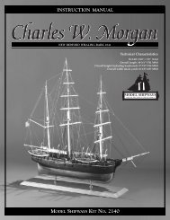
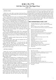
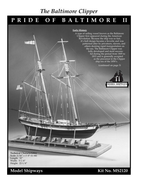
The Baltimore Clipper<br />
PRIDE OF BALTIMORE II<br />
Early History<br />
A type of sailing vessel known as the Baltimore<br />
Clipper first appeared during the American<br />
Revolution. Because the ship was so fast,<br />
it’s hull design became a favorite and was<br />
patterned after by privateers, slavers, and<br />
others desiring rapid transportation on<br />
the sea. The Baltimore Clipper was<br />
fully developed and most successful<br />
during the period from 1805 to<br />
1815 and is generally accepted<br />
as the precursor to the Clipper<br />
ship era of the 1850’s.<br />
(continued on page 3)<br />
Technical Characteristics<br />
Scale: 3/16” = 1’ 0” (1: 64)<br />
Length: 32”<br />
Width: 5-1/4”<br />
Height: 22-1/4”<br />
Model Shipways<br />
Kit No. MS2120
Instruction Manual<br />
The Baltimore Clipper<br />
Pride of Baltimore II<br />
1988<br />
By Ben Lankford, 1994<br />
Built-up Model by Bob Bruetsch, 1994<br />
Detail photos of actual ship by Bob Bruetsch, 1994<br />
The Model Shipways plans for Pride of Baltimore II were prepared in 1993<br />
and 1994. They were developed from the original design drawings for the ship by<br />
Naval Architect Thomas C. Gillmer. Mr. Gillmer was also the designer of the first<br />
Pride of Baltimore, and other replica ships such as the pungy, Lady Maryland, and<br />
the brig, Peggy Stewart.<br />
In addition to the design drawings, the Model Shipways plans incorporate<br />
current as-built details of the ship. A number of modifications were made to the<br />
original design drawings during construction, and even during the period following<br />
construction. Photographs were taken, and detailed measurements were<br />
made to assure an accurate representation of the ship in Baltimore, Maryland. The<br />
plans represent the ship as it appeared from October 1993 to April 1994.<br />
Model Shipways is indebted to Mr. W. Bruce Quackenbush, Jr., Executive<br />
Director of the Pride of Baltimore, Inc. ; Mr. Michael McGeady, Deputy Director;<br />
and Captains Jan Miles and Robert Glover. These people not only encouraged the<br />
project, but assisted with taking measurements off the ship, made numerous<br />
sketches of details, and provided descriptions of the various rigs and operations.<br />
With the ship continually on the move around the world, the project could not<br />
have been completed without their assistance.<br />
Copyright 1994<br />
Model Shipways, a division of Model Expo, Inc.<br />
Tobyhanna, PA 18466-1000<br />
4
(Continued from cover)<br />
It was as a privateer during the War of 1812 that the Baltimore<br />
Clipper became most famous. With sleek lines and few guns, the<br />
Baltimore Clippers were light and exceptionally fast. Their maneuverability<br />
made it possible to wreak havoc on the British; the<br />
speedy privateers could overtake and outrun the enemy with ease,<br />
and this enabled the privateering owners to take large profits from<br />
the many prizes they seized. When the war ended in 1815 with the<br />
Treaty of Ghent, the ship type began to diminish. Many of the<br />
schooners were sold to South American and Caribbean owners. By<br />
1860, the Baltimore Clipper was gone.<br />
During the 17th and 18th centuries, the waterways of the Chesapeake<br />
Bay provided an excellent home and work environment<br />
for the early settlers. The overseas demand for tobacco and new<br />
ships kept the area alive with commerce. Many talented shipwrights<br />
plied their trade at the numerous shipyards located on<br />
the Eastern Shore. One in particular, Thomas Kemp, departed for<br />
Baltimore and Fells Point in 1803 to seek his fortune and avoid<br />
the local competition. Establishing himself as a leader, he built<br />
many fast and notorious Baltimore Clippers. With the newly<br />
independent America’s need to establish itself in European trade,<br />
and develop militarily on the open seas, his success was immediate,<br />
and paved the way for others who migrated north. Because<br />
Baltimore had the investment capital, it could provide the higher<br />
wages that eventually drew the best builders and craftsmen, as<br />
well as the many excellent captains and sailors required to man<br />
the ships. With the turning away from shipping tobacco to the<br />
major export of flour, Baltimore became one of the most productive<br />
shipbuilding and shipping centers of the time.<br />
Although the ship type had been fully developed, the name Baltimore<br />
Clipper was not applied to it until the ship was almost<br />
extinct. The type was once called a Baltimore Flyer, and early<br />
records simply refer to it as a Virginia-Built Boat, or Fast Sailing<br />
Schooner: light and sleek, fast and seaworthy, it was a topsail<br />
schooner with extremely raked masts. It had a wide, flush deck<br />
to allow easy handling of the ship, and when fitted as a privateer,<br />
it had guns. The type seems to have developed from the<br />
Chesapeake Bay sloop, soon found to be too small.<br />
The Baltimore Clipper carved out a place for itself in history. The<br />
schooners facilitated the nation’s ability to win independence,<br />
and they helped the city of Baltimore establish its identity as a<br />
major shipbuilding center.<br />
The First Pride of Baltimore<br />
In 1974, officials from the City of Baltimore wanted to re-create a<br />
Baltimore Clipper as a means of providing public attraction to<br />
the Inner Harbor. They required that the craft be an authentic<br />
replication of an early 19th century Baltimore Clipper, and that it<br />
be built on location at the Inner Harbor waterfront.<br />
Thomas C. Gillmer, a noted author, historian, and former director<br />
of Naval Architecture for the U.S. Naval Academy in<br />
Annapolis, was hired as the designer. The bid for construction<br />
was won by the International Historical Watercraft Society, a corporate<br />
designation of Mr. Melbourne Smith of Annapolis, Maryland.<br />
Mr. Smith is a noted authority on Baltimore Clippers.<br />
The ship’s design was based on early drawings done in Britain<br />
during dockyard surveys after the war of 1812. The plans were of<br />
several original ships that were captured privateers. After reviewing<br />
them, it was decided that Baltimore’s ship would be 90 feet in<br />
overall length with a 23-foot extreme beam, adding up to 140 tons.<br />
In late 1976, the ship was officially<br />
named the Pride of Baltimore,<br />
taking it’s name from the nickname<br />
affectionately given to the<br />
famous Baltimore Clipper, Chasseur.<br />
The Chasseur was built in<br />
1813 at Fells Point in Baltimore<br />
by Thomas Kemp. (Note: the<br />
ship’s boat on the Pride of Baltimore<br />
II carries the name Chasseur.)<br />
Ship’s boat Chasseur<br />
The Pride of Baltimore was launched at Inner Harbor on February 27,<br />
1977 and sailed on May 1, 1977. The ship logged over 150,000<br />
miles sailing to and from such places as the Great Lakes, Spain,<br />
Europe and from Newfoundland to the Florida keys, and many<br />
other ports. On May 14, 1986, the Pride of Baltimore met hurricane<br />
winds on its return home from St. Thomas and was lost at sea<br />
along with four crew members.<br />
Pride of Baltimore II<br />
After a period of mourning, it was decided to replace the Pride<br />
of Baltimore. Late in 1986, Thomas Gillmer once again was<br />
hired as the designer. The contracted builder was G. Peter<br />
Boudreau, a shipwright, crew member, and a captain of the<br />
first Pride of Baltimore.<br />
Pride of Baltimore II was to be a larger ship: 108 feet overall with a<br />
26-foot beam, and weighing 197 tons. Among these and other differences,<br />
this schooner would have a greater cruising radius and<br />
be licensed by the Coast Guard for carrying passengers.<br />
The Pride of Baltimore II keel was laid on May 3, 1987 and the<br />
schooner was launched on April 30, 1988. It was commissioned on<br />
October 23 and on January 3, 1989 received full certification and<br />
put out to sea. Since then, the ship has sailed to many ports. The<br />
schooner’s permanent home is Inner Harbor, Baltimore, Maryland.<br />
While the Pride of Baltimore II is as authentic as possible, a few variations<br />
in design were required to meet today’s standards of economy<br />
and safety. Interior watertight bulkheads were provided for<br />
safety, and the ship was fitted with auxiliary engines and feathering<br />
props. These were required because of the busy ports the ship<br />
is scheduled to visit. The ship also has a steering wheel instead of<br />
a tiller arm typical of a 19th century ship. If fitted with a tiller arm,<br />
the Coast Guard would require a two-helmsman watch. To do this,<br />
the crew would have to be increased by four which was unacceptable<br />
to officials. Also, it was decided not to include a fore course<br />
on the foremast. Such a sail was probably carried on Baltimore<br />
Clippers of the past, but was only used in light wind conditions.<br />
This sail plan decision was made during the building of the first<br />
Pride of Baltimore.<br />
If fitted as a privateer, the Pride of Baltimore II would have to carry<br />
guns. So, the ship design included ten gun ports with five on each<br />
side. Simply for show, the schooner carries four large cannons and<br />
two small swivel guns.<br />
More History<br />
For a complete history of the Baltimore Clippers, and both the<br />
Pride of Baltimore and Pride of Baltimore II, consult the<br />
bibliography for some excellent books with many good<br />
photographs and drawings.<br />
5
CONSTRUCTION STAGES AND TABLE OF CONTENTS<br />
Brief History Cover, pg 3<br />
Introduction/Credits Pg 4<br />
Before You Begin Pg 7<br />
What You’ll Need to Start Construction Pg 7<br />
How to Work With the Plans & Parts Pg 8<br />
Painting & Staining the Model Pg 9<br />
Stage A: Framing the Plank-On-Bulkhead Hull Pg 10<br />
1. Bending Wood Pg 10<br />
2. Center Keel Assembly Pg 10<br />
3. Cutting the Rabbet Pg 10<br />
4. Installing the Keel/Stem & Sternpost Pg 11<br />
5. Installing the Bulkheads Pg 11<br />
6. Installing the Transom Framing Pg 12<br />
7. Covering the Mast Slots Pg 12<br />
8. Installing the Planksheer & Bulwark Stanchions Pg 12<br />
9. Installing the Hawse Timbers Pg 13<br />
10. Installing the Main Rail Pg 13<br />
Stage B: Planking the Plank-On-Bulkhead Hull Pg 14<br />
1. Getting Started Pg 14<br />
2. Planking Battens & Belts Pg 14<br />
3. Planking Butts Pg 14<br />
4. Spiling Pg 15<br />
5. Fastening the Planks Pg 15<br />
6. Planking the Outer Hull Pg 15<br />
7. Planking the Transom & Counter Pg 18<br />
8. Planking the Bulwarks Pg 18<br />
9. Planking the Deck Pg 19<br />
Stage C: Completing the Basic Hull Structure Pg 20<br />
1. Correcting & Sanding Pg 20<br />
2. Gunport Lids & Interior Rail Pg 20<br />
3. Swivel Gun Stocks Pg 20<br />
4. Natural Wood/Double Plank Option Pg 20<br />
Stage D: Mounting the Hull Pg 21<br />
1. Building-Ways Pg 21<br />
2. Mounting Board with Two Pedestals Pg 21<br />
Stage E: Adding the Hull Details Pg 21<br />
1. Locating Deck Fittings & Structures Pg 21<br />
2. Bow Fairlead Pg 21<br />
3. Cabin Trunks Pg 21<br />
4. Ventilator Boxes & Mushroom Vents Pg 22<br />
5. Binnacle Pg 22<br />
6. Steering Wheel & Box Pg 22<br />
7. Hatches Pg 22<br />
8. Deck Lockers Pg 24<br />
9. Samson Post & Bitts Pg 24<br />
10. Windlass & Chain Pipes Pg 24<br />
11. Catheads & Anchors Pg 24<br />
12. Pin Rails Pg 25<br />
13. Fife Rails Pg 25<br />
14. Bilge Pumps & Fire Stations Pg 25<br />
15. Deck Prisms Pg 25<br />
16. Rubber Pads Pg 25<br />
17. Steps Pg 26<br />
18. Lifelines Pg 26<br />
19. Life Rings Pg 26<br />
20. Cavels & Mooring Chocks Pg 26<br />
21. Channels Pg 26<br />
22. Eyebolts & Cleats Pg 26<br />
23. Props & Struts Pg 27<br />
24. Rudder Pg 27<br />
25. Swivel Guns Pg 27<br />
26. Cannons Pg 27<br />
27. Ship’s Bell Pg 27<br />
28. Running Lights, Stern Light & Crosstree Spotlights Pg 27<br />
29. Stern Flag Emblem Pg 27<br />
30. Ship’s Name Pg 28<br />
31. Ship’s Boat & Cradles Pg 28<br />
Stage F: Mast & Spar Construction Pg 29<br />
1. The Importance of Scale Pg 29<br />
2. Shaping & Tapering Masts & Spars Pg 29<br />
3. Building & Installing the Masts Pg 29<br />
4. Building & Installing the Bowsprit, Jibboom,<br />
Dolphin Striker & Jibboom Spreaders Pg 31<br />
5. Building the Fore Yards Pg 31<br />
6. Building the Main Boom & Gaffs Pg 32<br />
7. Ringtail & Studding Sail Booms & Yards Pg 32<br />
Stage G: General Rigging & Sailmaking Information Pg 33<br />
Rigging Terms Defined Pg 33<br />
1. Rigging Options Pg 33<br />
2. Using the Rigging Plans Pg 34<br />
3. Rigging Line Sizes & Colors Pg 34<br />
4. Wire vs. Rope Rigging Line Pg 34<br />
5. Treating the Lines Pg 34<br />
6. Belaying Pins & Their Lines Pg 34<br />
7. Rigging Tools Pg 36<br />
8. Blocks & Deadeyes Pg 36<br />
9. Sailmaking Pg 36<br />
10. Rigging the Model Without Sails Pg 37<br />
Stage H: Standing Rigging Pg 38<br />
1. Shrouds Pg 38<br />
2. Backstays Pg 38<br />
3. Running Backstays Pg 38<br />
4. Fore & Aft Stays Pg 39<br />
5. Bowsprit Rigging Pg 39<br />
6. Footropes & Studding Sail/Ringtail Lashings Pg 39<br />
Stage I: Running Rigging Pg 40<br />
1. Jib Topsail, Jib & Fore Staysail Pg 40<br />
2. Foresail Pg 40<br />
3. Mainsail Pg 40<br />
4. Ringtail Pg 40<br />
5. Main Gaff Staysail Pg 41<br />
6. Fore Topsail & Lower Yard Pg 41<br />
7. Studding Sails Pg 42<br />
8. Fore Topgallant Sail Pg 42<br />
9. Miscellaneous Rigging Pg 42<br />
10. Final Touches Pg 43<br />
Bibliography Pg 44<br />
Rigging Line Diameters Pg 44<br />
Scale Conversion Table Pg 44<br />
Millimeter/Inches Conversion Formula Pg 44<br />
6
BEFORE YOU BEGIN<br />
The Pride of Baltimore II is a very beautiful schooner and makes a<br />
splendid model. The plank-on-bulkhead hull construction with<br />
laser-cut parts offers a unique building experience. It assures an<br />
accurate hull form, and develops an understanding of how real ships<br />
are constructed.<br />
The kit is manufactured to a scale of 3/16” = 1’ 0” and reflects the<br />
scale of the plans. The kit is supplied with a set of Britannia, brass,<br />
and wooden fittings to eliminate problems in making or machining<br />
such parts from scratch, which may be beyond the ability or<br />
resources of the average modeler. Many of these fittings, however,<br />
will require final finishing before they are suitable for installation on<br />
the model. This will be especially true for the Britannia fittings and<br />
will be discussed later.<br />
This kit will provide less experienced modelers with the opportunity<br />
to acquire some scratch-building techniques. As an aid, various<br />
techniques will appear throughout the <strong>instruction</strong>s. While the modeling<br />
progresses, you will see where you may want to substitute<br />
some of the kit fittings with your own creations. By all means try<br />
them, especially if you think you can improve the model. The worst<br />
that can happen is a little lost time. But, the experience gained will be<br />
most valuable for future projects.<br />
If you are a beginner, take your time. This model has a considerable<br />
amount of detail and small parts. Make sure you complete one<br />
stage before moving to the next. When things go awry, consider<br />
doing it over.<br />
WHAT YOU’LL NEED TO START CONSTRUCTION<br />
The following tools and supplies are recommended for the construction<br />
process. Modelers who have built before may have their<br />
own favorites.<br />
A. Knives<br />
1. Hobby knife<br />
2. No. 11 blades<br />
B. Files<br />
Set of needle files<br />
C. Clamps<br />
1. A few small C-clamps<br />
2. Wooden clothespins<br />
3. Rubber bands, #16 and #33<br />
D. Tool Set<br />
A small carving tool set or individual gouges and chisels for carving<br />
center keel rabbets, stern filler pieces, tapering the keel/stem,<br />
and carving the ship’s boat.<br />
E. Sharpening Stone<br />
Necessary to keep tools razor sharp<br />
F. Boring Tools<br />
1. Set of miniature drills: #60 to #80<br />
2. 1/16”, 3/32”, and 1/8” drills<br />
3. Pin vise<br />
G. Miscellaneous<br />
1. Tack hammer<br />
2. Tweezers (a few)<br />
3. Small fine-pointed scissors<br />
4. Miniature pliers (small round and flat nose)<br />
5. Bench vise (small)<br />
6. Soldering iron or torch, solder and flux<br />
7. Sewing thread (black and tan for seizing)<br />
8. Beeswax block (for treating rigging lines)<br />
9. 1/2” or 3/4” masking tape<br />
10. Wire cutters (for cutting fine wire and strip metal)<br />
H. Sandpaper<br />
Fine and medium grit garnet or aluminum oxide sandpaper<br />
(#100 to #220)<br />
I. Sail cloth<br />
Light weave cotton, linen, or balooner cloth, if you intend to<br />
add sails. Model Expo carries a suitable fine weave 100% cotton<br />
muslin which is unbleached and doesn’t need dyeing.<br />
J. Finishing<br />
1. Paint Brushes<br />
a. fine point for details<br />
b. 1/4” to 1/2” flat square for hull<br />
K. Supplies<br />
(will be covered in detail in the Painting & Staining section<br />
and throughout the <strong>instruction</strong>s)<br />
1. Paints<br />
2. Primer<br />
3. Stains and varnish<br />
4. White or Carpenter’s (yellow) wood glue<br />
5. Super glue<br />
6. Five-minute epoxy glue<br />
7. Wood filler<br />
Note about glues: White glue, or Carpenter’s wood glue (yellow<br />
in color; also available in tan), will suffice for most of the model.<br />
Five-minute epoxy provides extra strength for gluing fittings.<br />
Cyanoacrylate glue (super glue), such as Jet, can be used for quick<br />
adhesion and is ideal for adding a touch to a rigging seizing to<br />
hold it in place. The best super glue for most applications is a<br />
medium viscosity gap-filling type. The watery thin type is recommended<br />
to fill a narrow crack by capillary action, and for quickly<br />
securing hull planking to the bulkheads.<br />
7
HOW TO WORK WITH THE PLANS & PARTS<br />
Before starting model construction, examine the kit and study the<br />
plans carefully. Familiarizing yourself with the kit will serve two<br />
purposes. First, it will let you determine that all parts have been<br />
supplied as listed. And second, you’ll be surprised at just how<br />
quickly handling the parts allows you to better understand the kit<br />
requirements. Try to visualize how every part will look on the<br />
completed model. Also, determine ahead of time what must be<br />
done first. The <strong>instruction</strong>s will help you in this regard, but a thorough<br />
knowledge of the plans at the outset is essential.<br />
It is suggested that all small fittings and hardware be sorted into<br />
labeled boxes or compartments to avoid loss during the building<br />
process.<br />
1. The Plans<br />
Six Plan Sheets are provided:<br />
1. Plank-On-Bulkhead Hull Patterns - Sheet 1 of 6<br />
2. Plank-On-Bulkhead Hull Construction - Sheet 2 of 6<br />
3. Hull Plan and Profiles - Sheet 3 of 6<br />
4. Hull and Spar Details - Sheet 4 of 6<br />
5. Rigging and Sails - Sheet 5 of 6<br />
6. Rigging Sections and Details - Sheet 6 of 6<br />
In addition, a set of sketches appears throughout the <strong>instruction</strong><br />
<strong>manual</strong> to further illustrate the various stages of construction.<br />
The Pride of Baltimore II kit is manufactured to a scale of 3/16” = 1’ 0”.<br />
Each plan sheet is drawn to the exact scale that the model is to be<br />
built, except where some details have been enlarged for clarity.<br />
Most often, a clarifying detail is twice as large as the model scale;<br />
3/8” = 1’ 0”. Most dimensions can be lifted directly off the plans by<br />
using a set of draftsman dividers or by using a “tick” strip, which<br />
is simply a piece of paper used to “pick up” the dimensions (a roll<br />
of calculator tape works very well). Lay your paper strip over the<br />
plan and mark the lengths of items carefully with a sharp pencil.<br />
Then use the strip to transfer the marks to the wood or item to be<br />
made to scale. When ticking the larger scale details, just cut the<br />
measurement in half.<br />
It is handy to have a triangular architect’s scale. Measuring and<br />
cutting parts using the 3/16” scale gives you a better feel for real<br />
ship sizes. You would need this scale for building a model with full<br />
ship sizes shown on the plans. However, the Pride of Baltimore II<br />
plans have already been converted and show only actual model<br />
sizes. Actual sizes were converted to the nearest 1/64”, or 1” full<br />
scale. Consequently, you will be working in increments of 1/64”.<br />
For example, if the actual size was 2-1/2” (or 5/128” model scale)<br />
it has been rounded up to 3/64”; close enough at this scale and it<br />
better fits the standard basswood sizes.<br />
2. Making Allowances Along the Way<br />
Try to be exact when following the plans, but use common sense<br />
along the way. You may need to make adjustments or allow for<br />
small differences in how your model is shaping up; perhaps your<br />
mast has too much rake (the angle at which it sits). When lines go<br />
to belaying points they should not drape over parts or conflict with<br />
other lines. If necessary, move a belaying point or a fairlead. In<br />
other words, put yourself on the ship and use your judgement.<br />
3. Understanding Hull Lines<br />
Beginners may not be familiar with hull lines. Buttock lines are vertical<br />
longitudinal planes cut through the hull. Waterlines are horizontal<br />
planes, and sections are transverse vertical planes. All of<br />
these lines define the hull shape and are used by the draftsman to<br />
fair the hull form (create regular even curves).<br />
A complete set of hull lines is not shown on the plans because they<br />
are not needed for this particular model. With the plank-on-bulkhead<br />
construction, the laser-cut bulkheads and center keel define<br />
the hull form. These are based on the Pride of Baltimore II designer<br />
hull lines to the outside of the planking, but are made smaller to<br />
allow for the thickness created by adding the planks. The Hull<br />
Planking Layout on Sheet 2 shows all the bulkhead lines together<br />
which are similar to a lines drawing body plan that shows the sections.<br />
Consult these lines when it is necessary to determine the<br />
hull form slopes. This will be necessary when installing the bulwarks<br />
since the bulwark stanchions are built separately from the<br />
lower bulkheads.<br />
4. Using Basswood Lumber<br />
Standard cut basswood is available in sheets and strips. Normally,<br />
thicknesses are available in 1/32”, 1/16”, 3/32”, 1/8”, 5/32”,<br />
3/16”, 1/4”, and 1/2”. Widths of strips are available in the same<br />
increments. Sheets may be 1”, 2”, 3”, or 4”. A thickness of 3/64” is<br />
a manufactured thickness, but not found in many catalogs. It is<br />
being supplied in this kit because it is needed for full-size ship<br />
thicknesses of 3”, as is the case for the main rail.<br />
Note: Your kit will contain either U. S. grown basswood or European<br />
limewood. Lime is similar to and just as good a model wood<br />
as our well-known basswood. In fact, it has superior steam bending<br />
qualities to basswood. Both woods are a similar species from<br />
trees called lime and linden. Limewood is often called basswood<br />
in Europe.<br />
For the model scale 3/16” = 1’ 0”, 1/64” is equal to 1” full ship<br />
size. 1/32” is equal to 2”, and so on. Generally, the available sizes<br />
of basswood fit the full ship size quite well and the strips or sheets<br />
can be used directly. Occasionally, you will find a size where the<br />
strip must be thinner than the basswood size supplied. In order to<br />
use a correct thickness, you will need to sand down a certain<br />
thickness of basswood. This is easily done with a sanding block<br />
before making a part.<br />
If you are fortunate enough to own a powered sanding thickness<br />
planer for models, all the better. These can be purchased commercially.<br />
You can also make your own, using a drum sander in a<br />
drill press. Clamp a block alongside the sander so the wood can<br />
be inserted between the block and sander. It’s a makeshift deal,<br />
but it works quite well.<br />
A thickness of 1/64” is required for many parts in this kit. Birch<br />
aircraft three-ply plywood could be used for this thickness. However,<br />
since it is birch, not basswood, it will not stain exactly the<br />
same as basswood. There is a lot of staining to be done, so it is<br />
preferable to stick with basswood so that the color will be uniform.<br />
Just bite the bullet and sand a 1/32” piece down to 1/64”.<br />
It is a good idea to sort the wood contained in the kit by thickness.<br />
When building a certain part, select a suitable size from the proper<br />
thickness pile. After cutting what you need, return the remaining<br />
piece to that thickness pile. This saves a lot of time looking for<br />
a given thickness. Don’t worry about using a piece for one item<br />
that was intended for another. It will all come out in the wash.<br />
There is enough extra wood in the kit so you should not run out<br />
before you complete the model.<br />
5. Cast-Metal Fittings<br />
The kit is supplied with Britannia metal castings. The Britannia<br />
metal is a great improvement over the white metal that was used<br />
in some older kits. Unlike white metal and pewter, Britannia does<br />
not contain lead, so there are no possible corrosion problems.<br />
Many of these fittings, however, will require final finishing before<br />
they are suitable for installing on the model.<br />
8
Before painting the cast-metal fittings, clean them up by<br />
removing all the mold-joint flash. To do this, use a No. 11<br />
hobby blade to cut the flash, then file or sand with fine sandpaper.<br />
It is also suggested that you clean the fittings thoroughly<br />
with warm soapy water before applying primer.<br />
Make sure they are rinsed thoroughly and allowed to dry<br />
before painting.<br />
6. Soldering & Working with Brass<br />
The Pride of Baltimore II is a replica ship of a period that had<br />
very little iron fittings. Consequently, you will not be<br />
required to do much soldering. Many of the fittings are cast<br />
Britannia. However, some items are difficult to cast or would<br />
be too soft, so these items must be made from brass strip and<br />
wire. Here are a few tips on soldering those or items you<br />
decide to scratch build.<br />
Brass sheet and strips can be cut with a small pair of tin snips<br />
or heavy scissors. Heavier brass will require the use of a jeweler’s<br />
saw. After cutting, all edges should be smoothed with<br />
needle files and fine wet-or-dry sandpaper. When cutting<br />
slivers from the brass sheet, you may notice that shears tend<br />
to bend the sheet sideways, as well as curl the piece. To<br />
straighten the edges in both directions, grip them with a pair<br />
of small pliers.<br />
Drilling holes in brass can be accomplished using small drills<br />
and a pin vise, which is a slow process. A Dremel Moto-Tool<br />
mounted on a Dremel drill press is ideal. This tool is worth<br />
the cost. Prior to drilling, use a small centerpunch to start;<br />
otherwise, these small drills tend to wander. Lubricate with a<br />
light oil and drill very slowly to avoid breakage. When using<br />
the Dremel, clamp the pieces in place or hold them down<br />
with a stick of wood. The brass will be very hot, so keep your<br />
fingers off!<br />
Soldering: The key here is to keep all brass parts clean. Use a<br />
solvent, or lightly sand, or both. Keep your fingers off to<br />
avoid grease spots. Soldering is easy if care is taken to set up<br />
your work area properly first. Use jigs or other holding<br />
devices, so the parts do not move around. Soldering can be<br />
done with a small torch or pencil soldering iron. First, add<br />
flux to the joint; just enough to do the job. The solder will flow<br />
where the flux is applied. Next, heat the joint.<br />
This sequence is important. The larger the parts, the longer it<br />
will take to heat the brass before the solder will flow. If you<br />
get too much solder on the joint, file it off with needle files.<br />
You’ll want the joint to look like the real thing, not a big glob<br />
of fillets.<br />
Solder: Today, there are many lead-free solders available and<br />
they are very strong. There is not much need to use pure silver<br />
solder. It is much more difficult to use because of the high<br />
melting temperature. Some of the lead-free solders have a<br />
small percentage of silver in the composition but the melting<br />
temperature is low.<br />
PAINTING & STAINING THE MODEL<br />
It may seem strange to begin an <strong>instruction</strong> <strong>manual</strong> with directions<br />
on applying the finishes to the model. Not so! Much time<br />
and effort can be saved, and a more professional result can be<br />
obtained, if the finishing process is carried out during construction.<br />
Proper timing in application of finishes and the use of masking<br />
tape to define painted edges should eliminate unsightly glue<br />
marks and splotchy stained surfaces. In the end, following these<br />
general suggestions will be to your advantage.<br />
Paint:<br />
Use a flat-finish paint such as the excellent model paints made<br />
by Model Shipways. You could<br />
also use artist’s paints by Jo Sonja (used by many bird carvers)<br />
or Holbein Acryla Gouache. These paints are a combination<br />
acrylic-gouache.<br />
Paint colors:<br />
The color scheme used for the Pride of Baltimore II is given on the<br />
plans. You will see color notes such as “color A.” In a notes column<br />
on plan sheet 3, the color A is described. In order to convey<br />
a more accurate color, commercial Floquil ship model or railroad<br />
model colors and stains, and Minwax stains are referenced. A<br />
color was selected as close as possible to the real ship colors.<br />
If you use a paint other than Model Shipways, match the Model<br />
Shipways color referenced on the plans with the paint you select,<br />
or get as close as you can.<br />
Primer:<br />
Use a grey primer. Model Shipways brand is excellent. The grey<br />
color will highlight sanding scratches and other defects better<br />
than white primer. Prime all woodwork to be painted, and prime<br />
all metal fittings. Lightly sand the primed items. Use a spackling<br />
compound, such as Pic-n-Patch brand, to fill any scratches and<br />
defects, then re-prime. Careful! Do not prime parts to be stained<br />
or varnished.<br />
Stains & Finishes:<br />
For natural finished wood, use a protective coating after staining,<br />
such as low sheen polyurethane varnish or the Floquil coatings.<br />
You can also use an oil-resin mix such as natural Minwax. Model<br />
Shipways stain, or Minwax stains can be used to tone the wood.<br />
Brushes & Procedures:<br />
Use good quality soft sable or synthetic hair artist brushes. A<br />
small pointed brush is good for details. For the main hull areas,<br />
use a 1/4 to 1/2 inch flat brush.<br />
Before painting, clean the model with a tack rag. Apply your<br />
paint in smooth even strokes, overlapping the strokes as you go.<br />
Thin the paint enough to eliminate brush strokes, but not run.<br />
You will need four or five coats of the light colors to cover the<br />
grey primer, and maybe only two coats of the dark. Check your<br />
finish between coats, and sand or add spackle as necessary to get<br />
rid of any blemishes.<br />
You will be told how to mark the load waterline location later.<br />
At this line, and anywhere else two colors meet, use masking<br />
tape. Electrician’s black plastic tape is ideal. It leaves a nice edge<br />
and is not overly sticky. Do not use drafting tape. The edges are<br />
wrinkled and paint may run under the edge.<br />
9
STAGE A<br />
FRAMING THE PLANK-ON-BULKHEAD HULL<br />
1. Bending Wood<br />
Building a P-O-B hull requires some wood bending<br />
and twisting, and the wood must remain in the<br />
desired position so as not to put too much stress on<br />
glue joints and fasteners. The term “steam-bent” will<br />
be used throughout the text whenever such a process<br />
is necessary. However, here are three ways to do it.<br />
Steam-bending–For actual steam-bending, hold the<br />
piece over a kettle of steaming water and bend. Hold<br />
the wood in position until it cools. It should remain<br />
nearly in that position, but may spring back slightly.<br />
Soaking–Another method is to soak the piece in<br />
warm water for several hours. Try adding a little<br />
household ammonia to the water. You can also use<br />
pure ammonia. This speeds up the soaking process<br />
and makes the wood fibers slippery so the wood is<br />
easily bent. Hold the wood in position with a form<br />
after soaking and let it dry completely.<br />
Hot iron–You may also bend wood quickly over a<br />
soldering iron, but don’t let it get too hot. A large soldering<br />
iron with a tubular end is ideal. The tube near<br />
the handle is not as hot as the very end. It is also possible<br />
to purchase model plank bending irons commercially.<br />
They are designed for controlled heat.<br />
2. Center Keel Assembly<br />
The first step in constructing the hull is to assemble<br />
the two laser-cut center keel pieces. First, use a sharp<br />
pencil and mark the bulkhead locations below the<br />
slots and the WL reference lines. One line is used to<br />
locate Bulkheads “A” through “L” and another for<br />
locating Bulkhead “M”. Mark on both sides of each<br />
center keel piece. Be especially critical in locating the<br />
reference lines. Measure from several points from the<br />
plans. The reference lines are a key to proper alignment.<br />
Place the two parts, 1 and 2, over a sheet of wax<br />
paper or plastic wrap, on a flat building board or<br />
table. Glue the joint with white or carpenter’s wood<br />
glue. Use a steel or aluminum straight edge to align<br />
the WL reference lines. Place a weight on each piece<br />
to hold it down while the glue dries. Let the glue dry<br />
at least overnight, preferably 24 hours (see figure 1).<br />
3. Cutting the Rabbet<br />
Cut the rabbet in the center keel. The bearding line is<br />
the intersection of the center keel and the inside face<br />
of hull planks. After the center keel is ready, mark the<br />
bearding line on both sides. The bearding line<br />
appears along the sternpost and the keel/stem. Measure<br />
from the P-O-B plans. Using a chisel, start the<br />
rabbet cut at the bearding line and cut toward the<br />
edge of the center keel. When the planking is<br />
installed, the planks will lie flush on the cut portion<br />
from bearding line to rabbet (see figure 2).<br />
10
4. Installing the Keel/Stem & Sternpost<br />
The ship has no real point of change between the keel<br />
and stem, so we will call it a keel/stem. The laser-cut<br />
keel/stem, and sternpost can now be added. Taper<br />
the keel/stem according to the plans before gluing in<br />
place or do it later. Dowels can be used to help align<br />
and hold the pieces. Remove any glue squeeze-out<br />
from the rabbet before it sets (see figure 3).<br />
An Option: If you like, you can glue the sternpost and<br />
keel/stem onto the center keel before cutting the rabbet.<br />
This makes cutting the rabbet a little more difficult,<br />
but on the other hand, it makes the installation<br />
of the sternpost and keel/stem easier since there is<br />
more gluing surface.<br />
5. Installing the Bulkheads<br />
The bulkheads are labeled “A” through “M”. Compare<br />
the laser-cut bulkheads with the plans to determine<br />
which is which, and label each bulkhead. Check<br />
each bulkhead to make sure it will slide into the center<br />
keel slots. Machine tolerances during laser cutting<br />
may provide a too tight fit. Sand the slots, if necessary,<br />
until the bulkheads slip on. The fit should be<br />
snug, allowing a little tolerance for glue.<br />
On each bulkhead, mark the location of the WL reference<br />
lines in pencil. This mark should line up with<br />
the WL mark on the center keel. It will assure that the<br />
hull form is accurate and that each bulkhead is correctly<br />
related to the others. There are two WL marks.<br />
One is for Bulkhead “A” through “L”, and the other<br />
is a higher mark for Bulkhead “M”.<br />
Next, mark the bevels on the bulkheads. Use a tick strip<br />
to transfer the bevel line as shown on the plans, or cut<br />
the bulkhead patterns from the plan and glue onto the<br />
bulkheads. You can also lay the pattern over the bulkhead<br />
and use a pin prick to locate the bevel. Cut the<br />
bevels with a #11 blade as shown (see figure 4).<br />
Some of the bevels are very slight, especially the deck<br />
bevels and the side bevels near amidships. These can<br />
be sanded after the bulkheads are installed instead of<br />
pre-cutting them.<br />
Glue the bulkheads in place, making sure that the<br />
WL marks on the bulkheads and the center keel line<br />
up. Use a square to make each bulkhead perpendicular<br />
to the center keel, then tack a temporary strip to<br />
the top to hold the bulkhead in place while the glue<br />
dries (see figure 5).<br />
After all bulkheads are in place, tack a temporary batten<br />
on each side of the hull just below the deck as<br />
shown. (see figure 6). This is a critical step. Measure<br />
the spacing between bulkheads and retack the battens<br />
until the hull is aligned. Even though the center<br />
keel was assembled flat, it could warp out of line. The<br />
result could be that you end up with a bananashaped<br />
hull. Check the spacing between bulkheads,<br />
and the port against starboard spacing. Look at the<br />
the hull to see if it is properly aligned.<br />
When you are satisfied that the hull is aligned, check<br />
to see that the bottom of each bulkhead feathers out<br />
and lies precisely on the bearding line. Trim as necessary<br />
to line up. Also, check to make sure that the<br />
top of each bulkhead at the centerline is flush or<br />
slightly higher than the center keel. Since all alignment<br />
is based on the WL marks, there could be some<br />
slight errors. If the center keel is below the top of the<br />
bulkheads, that’s OK. If above, trim the center keel<br />
until it is flush with the bulkheads (see Figure 7).<br />
FIG. 5 – Squaring the Bulkheads<br />
Reference<br />
lines must<br />
line up<br />
Glue<br />
FIG. 6 – Applying Battens<br />
Check spacings<br />
Bulkheads<br />
REF.<br />
FIG. 7 – Aligning the Bulkheads<br />
Sand flush with top of<br />
bulkheads if necessary<br />
REF.<br />
Check alignment<br />
visually in all<br />
directions<br />
REF.<br />
Smooth flow<br />
into rabbit<br />
Tack temporary<br />
strip until glue dries<br />
Check 90°<br />
with square<br />
Check straightness of center<br />
keel with straight edge<br />
Bearding line<br />
Tack temporary<br />
batten on hull<br />
Line up with reference<br />
line on center keel<br />
Trim if neccessary to line<br />
up on the bearding line<br />
11
Next, check the fairness of the hull form and sand in<br />
the slight bevels that were not pre-cut. To do this, use<br />
a stiff basswood batten about 3/32” thick and lay it<br />
across the bulkhead edges and deck in various locations<br />
(see figure 8). If not fair, sand the bevels that<br />
stick out, or add shim material if there are dips. This<br />
is an important check. The planks must lie flat<br />
against the bulkheads without incurring any bumps<br />
and dips on the surface. A model like the Pride of Baltimore<br />
II has many bulkheads, so it is possible for<br />
manufacturing or assembly errors to creep in.<br />
Critical Area: Planks from Bulkhead “K” to the sternpost<br />
rabbet take a severe bend. The bevel on Bulkhead<br />
“L” is critical. Check this area thoroughly so a<br />
batten curves smoothly from “K” over “L” and into<br />
the sternpost rabbet. Trim “L” if necessary. This area<br />
will require steam-bending. Otherwise, the planks<br />
may break or buckle as they pass over Bulkhead “L”.<br />
Option: To avoid the possibility of a break at “L”, you<br />
could fill the space from bulkhead “L” to the rabbet<br />
with a solid wood block, carved to the hull curvature.<br />
6. Installing the Transom Framing<br />
The transom framing is composed of a filler block<br />
port and starboard that is glued to the aft side of<br />
Bulkhead “M” and to the center keel. On top of the<br />
blocks you will glue six laser-cut inboard knees and<br />
two outboard knees. The outboard knees should<br />
slope inboard and curve on the outboard side to<br />
catch the bulwark planking which will require a lot<br />
of tumblehome aft near the transom.<br />
First, carve the two rectangular blocks provided in<br />
the kit in accordance with the plans (see also figure<br />
9). The top will need to be curved to the deck camber.<br />
The aft side of the blocks indicate the slope and curvature<br />
of the transom, and the counter below should<br />
be a curve, but straight across. Note that the front of<br />
each block will be exactly the same as the aft side of<br />
Bulkhead “M”.<br />
Add the laser-cut frame knees atop the carved blocks<br />
(see figure 10). The inboard knees are straight, but the<br />
outboard knees must be sanded to the hull curvature.<br />
The transom will be planked later. For now, you may<br />
want to tack a strip along the top of the knees so you<br />
won’t accidentally break them off as you proceed.<br />
7. Covering the Mast Slots<br />
On both sides of the mast slots in the center keel, add<br />
the pieces shown on the P-O-B plan. Cut from scrap<br />
wood. Glue them securely, because you can’t get to<br />
them after the decking is installed. The mast slots are<br />
slightly larger than the actual mast. The mast will be<br />
wedged in the hole when installed.<br />
8. Installing the Planksheer<br />
& Bulwark Stanchions<br />
The Pride of Baltimore II has a single planksheer (or<br />
call it a waterway). Inboard of the planksheer is a nibbing<br />
strake running parallel to the planksheer. The<br />
planksheer is provided laser-cut with holes for each<br />
bulwark stanchion. The planksheer is 1/16” thick like<br />
the deck planks. On the real ship, the planksheer is<br />
slightly thicker than the deck planks (about 3/8” to<br />
1/2”) but at 3/16” model scale this variance is not<br />
necessary. The planksheer will be painted, so the difference<br />
will not be seen.<br />
FIG. 8 – Fairing the Hull Form<br />
Needs shim<br />
(gap)<br />
FIG. 9 – Installing the Transom Framing<br />
Stern block<br />
P/S<br />
Transom slope<br />
P/S = Port & Starboard<br />
Needs trimming<br />
(bump)<br />
FIG. 10 – Adding the Frame Knees<br />
Knee (vertical)<br />
Deck camber curve<br />
Glue<br />
Stern block<br />
Good<br />
Good<br />
Heavy batten across<br />
several bulkheads to<br />
check fairness<br />
Counter curve<br />
Glue to “M”<br />
BHD”M”<br />
Temporary strip<br />
to hold knees<br />
Outboard knee<br />
angled inboard<br />
BHD “M”<br />
12
Glue the two-piece planksheer together, then glue it<br />
to the top of the bulkheads, port and starboard. The<br />
planksheer should extend beyond the edge of the<br />
bulkheads by 3/32”. After the hull planking is<br />
added, the planksheer will protrude out from the<br />
planks by 1/32”.<br />
The planksheer across the stern must be fitted<br />
between the stern knees as shown on the plans.<br />
The bulwark stanchions on the real ship are not<br />
extensions of the hull frames, but separate timbers set<br />
between frames. For the model, you will proceed in a<br />
similar manner except that the stanchions will go<br />
only to the bottom of the planksheer. The stanchions<br />
are provided laser-cut in the kit. Notice that the stanchion<br />
at the cathead is 1/8” wide while all others are<br />
3/32”. If for some unknown reason this particular<br />
stanchion was laser-cut like the others, simply add a<br />
piece of 1/32” sheet to the side to make the stanchion<br />
1/8” wide.<br />
The trick now is to install the bulwark stanchions so<br />
that they are properly angled and follow the hull<br />
form. Using the Hull Planking Layout drawing as a<br />
guide, and also paying attention to the shape of the<br />
bulkheads, install and glue a bulwark stanchion<br />
about every three or four inches. Check the angle and<br />
make sure it is exact. Next, insert the remaining stanchions<br />
in the planksheer holes, but before gluing<br />
these in place, add the inboard stringer at the top of<br />
the stanchions. This stringer will act as a guide for<br />
fairing the other stanchions. You may need to put<br />
some temporary strips between the port and starboard<br />
stringer to hold them to the correct shape.<br />
When satisfied with the alignment, add a touch of<br />
super glue at each stanchion to secure them in the<br />
holes (see figure 11).<br />
A stringer is also required at the inboard top of the<br />
stern knees. Glue this on at this time.<br />
Notice on the plans that each stanchion has chamfered<br />
edges on the inboard side. At 3/16” scale, it<br />
may be overkill to try to add these chamfers on the<br />
model. They would be more effective if the stanchions<br />
were made from a harder wood, such as cherry,<br />
and the scale were a little larger.<br />
9. Installing the Hawse Timbers<br />
The hawse timbers will be glued to the top of the<br />
planksheer. Fit the hawse timbers as shown on the<br />
plans (see also figure 12). Drill the hawse holes<br />
through the lower section as shown.<br />
10. Installing the Main Rail<br />
Cut the main rail from 3/64” x 1/2”-wide stock provided<br />
in the kit and according to the plans. Use several<br />
scarf joints in the main rail. Cut each section so<br />
the grain of the wood follows the rail. Fit the rail carefully<br />
on top of the bulwark stanchions. Drill some<br />
holes for alignment pins or dowels before gluing as<br />
shown (see figure 13).<br />
Most of the basic framing is now complete and you<br />
will begin the planking next. First, take a moment to<br />
look over what you have done so far. Re-check the<br />
fairness of the hull. Making corrections now will<br />
allow the planking process go smoothly.<br />
13
14<br />
STAGE B<br />
PLANKING THE PLANK-ON-BULKHEAD HULL<br />
Before getting started, it is a good idea to know some<br />
of the more common shipbuilding terms that apply<br />
to the planking process. Consider the following few<br />
key words as you work:<br />
1. A plank is a single length of wood used for planking<br />
a hull or deck. A planking strake is a continuous<br />
line of planks, butted end to end from bow to stern,<br />
or wherever the strake begins and ends.<br />
2. A garboard strake is that strake of planking adjacent<br />
to the keel.<br />
3. The sheer strake is the uppermost main hull strake.<br />
4. The wale is a heavy layer of strakes below the sheer<br />
strake along the length of the hull’s side.<br />
5. When discussing planking belts, we are talking<br />
about a group of planks along the hull. Belts are laid<br />
out using battens, which are temporary strips of flexible<br />
wood used to locate the belt. A ribband is also a<br />
batten, used on boats and ships to hold the frames in<br />
place while the planking is being added. Ribbands<br />
are removed as the planking is completed.<br />
6. Spiling is a term used to describe a process for<br />
marking and cutting a plank to a given shape.<br />
7. Edge-bending, also called springing, is when you<br />
bend a plank edgewise.<br />
8. When planking, the use of the word fair refers to<br />
smooth, gradual curves.<br />
9. Nib or nibbing is where one plank runs into another<br />
at a sharp angle. In order to eliminate the feathered<br />
edge, the plank is cut off on the end and it is fitted<br />
into a similar cut in the other plank. Nibbing is generally<br />
applied to decks, but hull planks are also<br />
nibbed.<br />
10. A stealer is a plank inserted into another plank, or<br />
notched in between two adjacent planks when the<br />
spacing between the planks gets too wide. Or, when<br />
two planks are tapering toward a narrow end, it may<br />
be necessary to cut off both planks, then substitute a<br />
wider plank to continue so there will be enough<br />
wood left for fastening the end of the plank. I’m at a<br />
loss for the proper term for this. One model publication<br />
calls it a joggle plank, but I’m not sure about that.<br />
Stealer is a common term , but joggle plank is not.<br />
11. The counter is the underside of the overhanging<br />
portion of a ship’s stern.<br />
1. Getting Started<br />
The planking process is tedious and you should plan<br />
on spending some time doing the job. Work on each<br />
plank as a project unto itself. Rushing will only result<br />
in frustration and a poor result.<br />
Since both sides of the hull will be identical, you can<br />
cut two planks the same shape at once. Fit the plank<br />
on one side, then the other. Before starting, place the<br />
hull upside down and secure it in a vise or cradle.<br />
Something portable would be ideal so you can rotate<br />
the hull easily.<br />
2. Planking Battens & Belts<br />
It is easier to plank a hull by first dividing the hull<br />
into a series of “belts”. The belts flow along the hull<br />
in smooth curves. Each belt is designed so the planks<br />
lay against the hull without having to excessively<br />
edge bend them. They sweep up at the ends like the<br />
deck sheer. Within each belt, the planks are usually<br />
spaced evenly, tapered, and fitted as required. The<br />
belts help accomplish the planking job without accumulating<br />
errors as you work.<br />
When selecting a belt width and the number of<br />
planks within each belt, you need to consider how<br />
the planks will lay against the frames and how they<br />
will taper. If the planks are too wide, they will not lay<br />
flat on the bulkheads. Also, you don’t want them to<br />
taper so much that there is no width left for fasteners.<br />
This would require substituting a larger plank for<br />
two to increase width. Also, in some areas, the planks<br />
may get wider rather than taper. If they get too wide,<br />
a stealer plank must be cut into the plank. While<br />
these alterations are acceptable and are used on<br />
many ships, it is best to design the run of planking to<br />
limit the number of such inserts (see figure 14 which<br />
illustrates some of these inserts).<br />
For the Pride of Baltimore II model, a planking layout<br />
has already been developed for you. The layout is<br />
taken from the actual ship and is shown on the P-O-B<br />
plans. The belts are not necessarily related to how the<br />
real ship was planked, but were selected for the convenience<br />
of the model maker. The real ship planking<br />
has been followed as closely as possible and was<br />
based on photographs and several key measurements<br />
of planking widths. Stealers have been placed<br />
where they were found on the real ship.<br />
3. Planking Butts<br />
Before you start, consider the planking butts. Since<br />
the lengths of wood cut from trees are generally<br />
shorter than the overall lengths of real ships, shipbuilders<br />
generally have to work with planks only 20<br />
or 30 feet long. Some modelers think it is easier to use<br />
a plank length the full length of the model. Fake butts<br />
can be scribed in later or omitted. Granted, this can<br />
be done. It’s really up to the modeler. By using shorter<br />
pieces, however, there are some advantages. Since<br />
all planks taper to some degree, using the shorter<br />
piece will let you mark the taper quick, and the plank<br />
will be easier to fasten in place. And with a short<br />
piece, only one hand is necessary to hold it down.<br />
Also, if you make a mistake, you only have a small<br />
piece to do over. So, the following is based on the use<br />
of the shorter lengths.<br />
Planking butts will not be exactly like the real ship.<br />
Because the model is designed to be built on the bulkhead<br />
system, no attempt was made to identify all the<br />
butts,so a deviation from the real ship planking butts<br />
was necessary.<br />
A plank length approximately 6 inches will cover<br />
four bulkhead spaces. This is a comfortable length to<br />
handle for this model. To scale, it is a plank 32 feet<br />
long. However, to avoid having very short pieces at<br />
the bow and stern, you may need to use a longer<br />
plank to complete the run.<br />
To follow real ship rules, you should stagger the butts<br />
on the model (see figure 15 for a sequence that is similar<br />
to that of a real ship). The stagger also applies to<br />
the deck planking. The 6-inch long plank works well<br />
with the rules. With this length you can meet the rule<br />
for three full plank-widths between butts on a single<br />
frame. If you use a plank length to cover only three<br />
bulkhead spacings, this would not be possible. Since<br />
the butts occur on bulkheads, you would wind up<br />
with only two full planks between the butts.
4. Spiling<br />
Edge-bending planks on a real ship is done, but it is<br />
limited. The wood is very stiff, so many planks must<br />
be cut to shape. Spiling is the term used for laying out<br />
the cuts (see figure 16). It’s simply a matter of transferring<br />
curves to a straight plank, then sawing the<br />
plank to shape. For the Pride of Baltimore II model, the<br />
wide planks landing at the sternpost should be the<br />
only strakes you need to spile. For narrow planks, the<br />
basswood strips are flexible enough so they can be<br />
edge-bent in place.<br />
5. Fastening the Planks<br />
There are some fancy plank clamps on the market,<br />
but they are more trouble than they are worth. They<br />
must be screwed into the edge of the bulkheads, leaving<br />
big holes to contend with when doing subsequent<br />
planks. With short pieces, you can hold or pin the<br />
planks in place. Be careful not to split the plank with<br />
the pins. If necessary, drill a small pilot hole first.<br />
Glue each plank to the bulkheads, and edge-glue<br />
them together. For the edges, use white or carpenter’s<br />
wood glue so that setting will not occur too fast. At<br />
the bulkheads, it is good to use thin super glue to<br />
quickly secure the plank in place. Be careful not to<br />
glue your fingers.<br />
While glue alone will hold the planks, you may wish<br />
to use small brass brads or wooden treenails for additional<br />
holding power, or just for looks. Using fine<br />
brass brads, cut off and discard the heads, then hammer<br />
them into place. If treenails are desired, you can<br />
buy them commercially. Better yet, get some long<br />
bamboo skewer sticks, strip off small pieces, then pull<br />
them through a draw plate until you have very small<br />
dowels. Drill holes for the treenails, add a touch of<br />
glue, and drive them into place. Treenails are good if<br />
you want to add them for each frame. While there are<br />
no frames, only bulkheads, use the bulwark stanchions<br />
for locating where a frame would be.<br />
6. Planking the Outer Hull<br />
Belt Layout: Now the fun begins! The hull is divided<br />
as follows: a single strake below the planksheer, a<br />
wale below that strake, then four belts A through D.<br />
The wale is a thick band of planking which cannot be<br />
varied from the real ship. The lower planking, on the<br />
other hand, could be slightly different and would not<br />
be noticed. The wale will be painted a light color.<br />
From the Hull Planking Layout drawing, use a tick<br />
strip along each bulkhead location and mark the wale<br />
location and the belt seams below. Using a tick strip,<br />
transfer the location of the seams on each bulkhead<br />
and mark them with a pencil. Now, using 1/16” x<br />
3/32” temporary basswood battens, lay the battens<br />
along the marks and temporarily tack them in place.<br />
The purpose of the battens is to assure an accurate<br />
flow of the planking belts. Although the Hull Planking<br />
Layout was developed to provide an accurate<br />
flow of belts, errors in drafting and tick strip marking<br />
and transferring may occur. With the battens actually<br />
in place, these errors can be corrected.<br />
With all the battens in place, visually check their<br />
flow. Look at the model from the side and from the<br />
bow and stern. Do the battens have nice smooth<br />
curves Adjust the battens if necessary (see figure<br />
17). The plans show what they should look like from<br />
the side and ends. When everything seems okay,<br />
remark the belt seam lines on the bulkheads, making<br />
sure they are clearly indicated. You do not want to<br />
15
FIG. 17 – Batten Layout<br />
Look for smooth flow<br />
of battens<br />
Planksheer<br />
Bottom wale<br />
Main rail<br />
“A”<br />
“B”<br />
“C”<br />
“D”<br />
Battens<br />
lose them. You could now remove the temporary battens<br />
or leave them in place until they need to be<br />
removed in order to add a plank.<br />
Sloping Plank Edges: As you proceed with the planking,<br />
you may need to slope the edges of a particular<br />
plank so it butts flush against the adjacent plank. This<br />
is especially true for a plank adjacent to another<br />
member intersecting at an angle. For example, the<br />
first plank below the planksheer at the bow butts<br />
against the planksheer at an angle. The edges of these<br />
planks must be trimmed so they fit against the<br />
planksheer (see figure 18).<br />
To begin with, all of the planks on the hull have<br />
square edges. When butted against each other on a<br />
round hull form, a small gap will appear between<br />
each plank. Most of the gaps eventually will be filled<br />
with glue, or you can fill them with wood filler. On a<br />
real ship, the gaps are caulked. In fact, the edges of<br />
the planks are often sloped to increase gapping. This<br />
measure assures that the inside of the planks butt<br />
against each other, while on the outside there are sufficient<br />
gaps for caulking. If you want a perfectly<br />
smooth hull without the gapping, you must trim the<br />
edge of each plank as you fit it. It’s a lot of work, but<br />
your decision.<br />
First strake below the planksheer: This is a single<br />
strake that is 1/16” thick by 3/32” wide from bow to<br />
stern. You will not taper it. Edge-cut the plank so it fits<br />
flush to the underside of the planksheer. Note that at<br />
the bow, the wale rides up to the planksheer. Run the<br />
plank forward, then when doing the wale, just add a<br />
doubler over the plank so that it will be the same thickness<br />
as the wale (see figure 19).<br />
Wale: The wale is made up of three planks that are<br />
3/32” thick. The planks will need to taper toward the<br />
stern since the overall wale should taper. Make each<br />
plank equal in width. On the real ship the wale is<br />
thicker than the hull planking, but not quite as much<br />
as you will get using a 1/16” hull plank and a 3/32”<br />
wale plank (a 2” difference on the real ship). If you<br />
desire, sand the wale down a little so it is not so thick.<br />
At this model scale, however, it is probably not necessary.<br />
The aft end of the wale and the counter planks intersect<br />
in a miter joint. See the expanded counter view<br />
on P-O-B plan sheet 2.<br />
FIG. 18 – Sloping the Plank Edges<br />
FIG. 19 – First Strake Below the Planksheer<br />
Wale planks<br />
FIG. 21 – Stealers in Belt D<br />
First plank strake<br />
(Bow area)<br />
Planksheer<br />
Edge must be<br />
sloped and fitted<br />
Doubler at bow to<br />
match wale thickness<br />
Sternpost<br />
Stealers<br />
16
Laying the Planks in Belt A: Each belt of planking<br />
should be done separately. Consequently, you can<br />
start with any belt. For discussion, let’s start at the<br />
top and work down. Belt A has six 1/16”–thick plank<br />
strakes below the wale. The maximum plank width is<br />
at Bulkhead G and is roughly a 9” real ship width (a<br />
little over 1/8” model scale). The planks should taper<br />
both forward and aft to about 3/32”. On the real ship,<br />
the planks taper to no less than 5-1/2”. Use the 1/16”<br />
x 3/16” strips for the planking in this belt.<br />
Use a tick strip and lift the plank widths from the<br />
Hull Planking Layout on Sheet 2. If you have<br />
changed the locations of the battens, simply divide<br />
the space into six equal plank widths at each bulkhead.<br />
A set of proportional dividers would help.<br />
Mark these lines on the bulkheads with a pencil. You<br />
will then have a completely marked area for Belt A.<br />
The next step is to cut planks to fit between the<br />
marks. Belt A will not require spiling, so a straight<br />
tapered plank can be made. Start at Bulkhead G. Use<br />
four planks, one from Bulkhead G to Bulkhead K,<br />
another from K to the transom, Bulkhead G to Bulkhead<br />
C, and Bulkhead C to the stem. First, lay a piece<br />
of planking material over the bulkheads and mark<br />
the length. Mark the plank in pencil at each of the<br />
bulkheads. Next, use a set of dividers or a tick strip<br />
and lift the plank widths from the marks on the bulkheads<br />
and transfer to the plank. Draw a line through<br />
the points and cut the plank. You now have a tapered<br />
plank. Trace this plank to obtain another one for the<br />
other side of the hull.<br />
Install the planks on the hull, butting them up against<br />
the wale. Then, do the same process for the next<br />
strake below. Stagger the butts for this strake. Install a<br />
plank from Bulkhead F to B, B to the stem, F to J, and<br />
J to the transom. You should have four planks making<br />
up each strake from bow to stern (see figure 20).<br />
At the stern, some planks will need to be twisted into<br />
place. You may need to steam bend the twist if it is<br />
severe.<br />
Now move down to the next planking strake and<br />
work it the same way as you did the previous one.<br />
Stagger the plank butts, starting at Bulkhead E. Continue<br />
until this strake is finished, then complete the<br />
strakes in Belt A.<br />
For now, let the aft ends of the planks that rest on the<br />
counter extend just beyond the counter. When you<br />
plank the counter, the counter and hull planks should<br />
meet in a miter like the wale noted previously.<br />
Laying the Planks in Belt B: This belt is very similar to<br />
Belt A. It has six plank strakes about the same width<br />
as those in Belt A. If you have not removed the temporary<br />
batten, do it now. Then you may start the<br />
process for Belt B. Remember to stagger the butts.<br />
Laying the Planks in Belt C: This belt is also similar to<br />
Belt A except that the planks do not get tapered as<br />
abruptly at the stern. Also, there are seven, rather<br />
than six, strakes. As mentioned when you were checking<br />
the fairness of the bulkheads, the area near the<br />
sternpost takes a severe bend. Steam-bending this<br />
area is essential, otherwise the planks may break or<br />
knuckle as you lay them over Bulkhead L. You can<br />
also use the filler block as an option.<br />
Laying the Planks in Belt D: This belt will contain the<br />
garboard strake (next to the keel) and two other<br />
strakes. It will also contain three stealers in order to<br />
reduce the width aft as shown (see figure 21). All the<br />
planks in this belt will be very wide (about 13” fullship<br />
size) and must be spiled. You will need to use the<br />
wide planking strips provided in the kit. There will<br />
also be some severe twist to the forward part of the<br />
planks. The twist should be steam-bent.<br />
Toward the bow, the planks will feather out at the<br />
rabbet rather sharply. This is fine for the model, but<br />
on the real Pride of Baltimore II, four of the lower<br />
planks have nibs in them as shown (see figure 22).<br />
You may do this if you desire.<br />
P-O-B plan sheet 2 has a complete planking profile as<br />
shown. Use this drawing to determine the plank<br />
widths in Belt D. The sections, Hull Planking Layout<br />
drawing , cannot show all the planks aft so the profile<br />
view is necessary.<br />
Plank Variations within a Belt: Suppose you are working<br />
within a belt, and have five planks the same<br />
width, and then find that the last plank in the belt<br />
needs to be made slightly wider to complete the<br />
belt...should you worry Certainly not. No planking<br />
job, even on real ships, is that precise. You are dealing<br />
with hand-cut planks. The important thing is to keep<br />
the flow of planks smooth. A variation in widths is of<br />
no great concern. Even though this kit tries to duplicate<br />
the planking on the real Pride of Baltimore II, you<br />
must be realistic. There are going to be some slight<br />
variances as you proceed.<br />
17
7. Planking the Transom & Counter<br />
For the model, the side hull planks can be extended<br />
past the counter (bottom curved portion of the stern<br />
overhang), and the 1/16”-thick counter planks<br />
butted into the hull planks or vice versa. On the real<br />
ship, however, the counter plank meets the hull<br />
plank in a miter joint. If you elect to do this, first cut<br />
the ends of the hull plank that you left hanging over,<br />
then add the counter planks. Cut the miter on each<br />
plank, then glue them in place (see figure 23). You<br />
could also cut the miter as you add each side plank.<br />
Add a strip to the upper edge of the counter planking<br />
so it covers the end grain. Round this edge like the<br />
molding above it.<br />
Plank the outside of the transom with 1/32”-thick<br />
planks (see figure 24). The section below the molding<br />
strip can be made from 1/32”-wide material. On the<br />
real ship, the upper part is mahogany and the planks<br />
can be seen. The lower section should either be<br />
planked or you may use a wide sheet (It was not possible<br />
to decipher this detail from photographs taken<br />
of the transom). Over top of the 1/32” planks, add<br />
the 1/32”-thick fancy piece and the molding strip.<br />
Leave a little gap in the upper horizontal molding for<br />
inserting the Maryland flag emblem.<br />
The inside of the transom will not be planked, so<br />
make sure you remove any glue squeeze-out<br />
between the outer plank seams and along the stern<br />
knees.<br />
8. Planking the Bulwarks<br />
The planks between the planksheer and main rail<br />
will be in two thicknesses. There are five planks that<br />
are 1/32”-thick, and a 3/64”-thick plank at the top.<br />
Check the width of the inboard stringer, the head of<br />
the bulwark stanchions, and the outboard thick<br />
strake. The total width must be correct since these<br />
pieces must fit under the main rail. If any one part is<br />
oversize it won’t fit. You should not have to make the<br />
rail wider to cover a mistake. The rail would look<br />
bulky and be out of scale.<br />
The bulwark planks are fairly uniform and will not<br />
require any severe tapering forward or aft. If you do<br />
not want to use the five planks, you may use only<br />
two, or even a solid piece. The real ship, however,<br />
was planked as described. Simplification is up to you<br />
and it is certainly justified if you intend to paint the<br />
model.<br />
As you plank the bulwarks, remember that there will<br />
be no planking inboard so you should clean up any<br />
glue squeeze-out on the inside as you plank. If left to<br />
harden, it would be difficult to remove.<br />
Note that there will be a continuous scupper along<br />
the side, so the lowest bulwark plank should not<br />
touch the planksheer from gunport 2 to 5 (see figure<br />
25). There is a real ship gap of 1” at the deck. For the<br />
model, you could cheat a little and use about a 1/32”<br />
gap rather than 1/64” so it shows up better. Forward<br />
and aft of the two gunports, small drilled scuppers<br />
are used.<br />
18
The top 3/64” plank should continue across the gunports.<br />
Apply a 1/32”-square vertical strip of wood on<br />
each side of the gunport, simply to cover the end<br />
grain of the bulwark plank (you could omit this on<br />
the model).<br />
Next, fit a fashion piece on each side of the transom<br />
as shown (see figure 26).<br />
9. Planking the Deck<br />
Hatch & Trunk Coamings: Before planking the deck,<br />
you must decide how you want to treat the hatch and<br />
trunk coamings. A recommended approach for doing<br />
it the way it was done on the real ship, is to install all<br />
coamings first. You can then plank around the coamings.<br />
This saves some planking work and material.<br />
On the underside of the coamings, insert some scrap<br />
wood so the deck planks have support for gluing (see<br />
figure 27).<br />
If you elect not to install the coamings now, they<br />
must be included in the construction of the hatches<br />
and trunks and glued down on top of the deck.<br />
Deck Planks: The deck planks should be 1/16” thick<br />
x 3/32” wide except for a 1/16” x 3/16” plank port<br />
and starboard at the centerline. On the real ship, the<br />
two center wide planks are just slightly thicker than<br />
the other planks. It is not necessary to indicate this<br />
variation in size at this 3/16” model scale.<br />
Prepare the strips by painting one edge black or dark<br />
brown. When the planks are glued together, this will<br />
simulate caulking in the seams. You can also use a<br />
brown colored carpenter’s wood glue on the edges of<br />
the planks. When dry, this glue is dark enough to<br />
simulate the caulking.<br />
Thick Pads: There are some thick pads that must be<br />
put on the deck around the windlass (used on the<br />
real ship to take abrasion from the anchor chain). The<br />
pads are shown on the plans. Add these doublers on<br />
top of the deck planks.<br />
Deck Inserts: As shown on the plans, there is an<br />
insert located under each of the fife rails. These<br />
inserts should be flush with the deck planking. You<br />
can add them as you plank the deck, or just omit<br />
them. The inserts are stained the same color as the<br />
fiferail so you could just stain the area rather than<br />
actually adding the insert.<br />
Deck Planking Procedure: The deck planks should be<br />
laid parallel to the centerline. Start at the centerline<br />
and work outboard. The nibbing plank is a narrow<br />
plank running parallel with the planksheer. Cut the<br />
nibs into the edge of the planksheer as you go (see<br />
figure 28).<br />
Scrape off any glue squeeze-out before going to the<br />
next plank. Planking butts can be used, like the outer<br />
hull, or they can be omitted. On the real ship, they do<br />
not show up as readily as the seams. You can also<br />
scribe butts after the planks are laid. Since there is no<br />
cutting or curves involved like there was with the<br />
hull planking, using long deck strips is no problem.<br />
Use brads or treenails if you like. See Hull Plank discussion.<br />
19
STAGE C<br />
20<br />
COMPLETING THE BASIC HULL STRUCTURE<br />
1. Correcting & Sanding<br />
After all the planks are installed, look over the entire<br />
hull. If you find seams with starved glue joints, rub<br />
some wood glue in the cracks and, if necessary, add<br />
some wood filler. When seams are filled, sand the<br />
entire hull and deck plank smooth.<br />
2. Gunport Lids & Interior Rail<br />
The gunport lids can be made now or you could add<br />
them later. Make the gunport lids from three planks,<br />
1/32” thick, or you may use a solid piece. Make the<br />
hinge straps from brass strip. Inboard, add the small<br />
rail across the gun ports (see figure 29).<br />
3. Swivel Gun Stocks<br />
A swivel gun stock is a post with a hole in the top that<br />
guns can be set upon and pivoted. Some ships have<br />
several stocks along the bulwarks. There are two stocks<br />
on the Pride of Baltimore II, one port and one starboard.<br />
These stocks are shown on the outboard profile of the<br />
plans but are actually “fake” stocks (as shown). Each<br />
stock should stop just below the main rail. The swivel<br />
gun for each stock should be set into a hole in the center<br />
of the main rail both port and startboard (rather<br />
than in the top of the stock). This is interesting because<br />
Tom Gillmer’s original design drawings show an actual<br />
stock extending above the rail with the swivel gun in<br />
the stock itself. This was just another change made during<br />
the building process.<br />
Notch out the fake gun stocks to fit the hull shape<br />
along the planksheer.<br />
4. Natural Wood, Double Plank Option<br />
Most wooden ships have single-thickness planking, as<br />
does the Pride of Baltimore II. Furthermore, the kit is<br />
intended to be painted the colors of the real ship. Many<br />
modelers, however, are familiar with the European<br />
double-planked kits, or want to have a natural wood<br />
tone finish on the hull, typical of the Admiralty type<br />
models. Also, after the planking job is completed, some<br />
modeler’s wish to try again to improve the looks of the<br />
job. If this is your desire, you may double plank the<br />
model right over the basswood planking.<br />
To complete the double planking task, thin wood strips<br />
in mahogany, walnut, and some other types of exotic<br />
hardwood can be purchased from Model Expo. For the<br />
Pride of Baltimore II, you will need 85 strips sized 0.5mm<br />
x 5mm x 20 inches long. This amount includes about 20<br />
percent increase for waste and errors.<br />
The natural wood planks will cover the existing planking,<br />
but you will still have a basswood planksheer and<br />
main rail exposed. You could substitute these initially<br />
with the wood of your choice, cap them with the<br />
strips, or simply stain them to look similar.<br />
When applying the strips, proceed exactly as you did<br />
for the basswood planking process. You may want to<br />
work with longer strips since the basswood planking<br />
already defines the plank shapes. Simply lift dimensions<br />
from the hull and cut the natural wood strips.<br />
When completed, sand and finish the hull with Floquil<br />
oil or glaze, or tung oil. Finally, add a coat of wax<br />
and then polish it.
STAGE D<br />
MOUNTING THE HULL<br />
Before continuing with additional work it is best to<br />
mount the hull. Doing this step will help prevent<br />
details from becoming damaged while you handle<br />
the model. It will also allow you to make any alignments<br />
that require a true waterline. So, proper<br />
mounting of the hull is very important. While any<br />
modeler can devise his own mounting, this kit contains<br />
a building-ways mounting system. A second<br />
option, which can be purchased separately, is a<br />
mounting board with two brass, or wooden,<br />
pedestals.<br />
1. Building-Ways<br />
The building-ways mounting system is mostly suitable<br />
for models without sails. The one contained in<br />
the kit is similar to the actual building-ways used for<br />
constructing the Pride of Baltimore II at Baltimore,<br />
Maryland’s Inner Harbor.<br />
You must drill the keel of the model in order to apply<br />
the rods that anchor the model to the ways. The<br />
building-ways are easily assembled, consisting primarily<br />
of 3/16” square stock, representing square<br />
timbers (see figure 30 for actual construction). The<br />
ways should be mounted on a baseboard sized<br />
approximately 24” x 9”. The board must be purchased<br />
separately, or you may make your own.<br />
Expanding the size of the board will allow you to create<br />
a mini-diorama comprised of boat yard ground<br />
activity. At Inner Harbor, the lowest wide timbers<br />
were set directly on the ground.<br />
2. Mounting Board with Two Pedestals<br />
As an option, you can purchase two brass or wooden<br />
pedestals. You will need a 1” long and a 1-3/8” long<br />
pedestal, or any length with one about 3/8” longer<br />
than the other. If you own a router, or can borrow<br />
one, you will be able to cut a nice fancy edge on the<br />
baseboard if you do not purchase one commercially.<br />
Finish the base with a dark stain or paint.<br />
If you decide to use the mounting board and<br />
pedestals, drill pilot holes in the keel and screw holes<br />
in the mounting board. Locate the pedestals so the<br />
load waterline is parallel to the mounting board. Plan<br />
sheet 3 shows the approximate location of the two<br />
optional pedestals. If something went awry and the<br />
balance is off, add a brass shim under one pedestal to<br />
correct it.<br />
If you intend to put the model in a glass or plastic<br />
case, you could let the bottom of the case serve as a<br />
baseboard.<br />
Note: It is recommended that either choice mounting<br />
piece be finished before mounting the Hull Assembly<br />
into place.<br />
STAGE E<br />
ADDING THE HULL DETAILS<br />
1. Locating Deck Fittings & Structures<br />
If you included the coamings when planking the<br />
deck, you at least have those structures located. Now<br />
it is time to locate all the other items that must be<br />
added: on the deck, inside bulwarks, and top of the<br />
rail; this includes items such as fife rails, bitts, windlass,<br />
deck prisms, binnacle, watertight steel hatch,<br />
steering wheel box, ship’s boat cradles, ventilator<br />
boxes, mushroom vents, fire hydrants, bilge pumps,<br />
pin rails and belaying pin holes in the rail, eyebolts,<br />
cleats, catheads, lifelines and stanchions, swivel<br />
guns, and deck lockers. Outboard, you will locate the<br />
propeller struts, shaft log, channels, and eyebolts for<br />
bowsprit rigging, rudder preventer chains, and rudder<br />
pintles and gudgeons.<br />
To locate items, measure from some known “bench<br />
mark” such as the center of a mast, the centerline, or<br />
outboard from the keel/sternpost intersection. The<br />
centerline has those two wide deck planks so it is<br />
easy to find. Mark all items lightly in pencil.<br />
Fittings such as eyebolts and cleats associated mostly<br />
with rigging can wait until later. However, it is not a<br />
bad idea to get all these fittings installed while working<br />
on the deck. Get them done, then clean up and<br />
varnish the deck. Afterward, when you start the rigging,<br />
you will be glad all those fittings are ready.<br />
2. Bow Fairlead<br />
Make the fairlead at the bow from wood and drill the<br />
five holes for lines leading toward the bow pin rail<br />
platform. Paint the fairlead black.<br />
3. Cabin Trunks<br />
The crew berthing access trunk, main salon trunk,<br />
engine room trunk, and after cabin trunk are all similar<br />
in general construction, but the companionways,<br />
skylights, and other top details vary on each trunk.<br />
Follow the plans carefully and do not make any<br />
assumptions that one item looks like another.<br />
The basic box for each trunk should be made from<br />
3/64”-thick basswood. You could also use a solid<br />
block. The kit contains a chunk of basswood for this<br />
purpose (see figure 31 for the basic structure and how<br />
it fits upon the deck coamings). If you did not install<br />
coamings while installing the deck planking, the figure<br />
also shows the detail which must be made now.<br />
The top of the main salon trunk and the after cabin<br />
trunk must be planked. The outboard wide plank<br />
and the fore and aft end planks on the real ship are<br />
mahogany, so on the model, they should be<br />
mahogany in color. The top planking within these<br />
planks on the real ship looks exactly like the main<br />
deck planking. It is Douglas fir with a weathered<br />
grey look, and you can see the caulking seams. The<br />
other trunks have all mahogany tops. With so many<br />
fixtures attached, you could use solid sheet wood for<br />
the top on the model.<br />
All of the companionways, skylights, etc. can be<br />
made and just glued on the tops of the trunks. If you<br />
want to have any one of the companionways, or<br />
hinged covers open, you must cut out an opening in<br />
the top and do some detailing below.<br />
21
Some details of the various components on the tops<br />
of the trunks are shown (see figure 32). Companionway<br />
slide rails and some of the other components<br />
must be 1/64” thick. Sand down the 1/32” stock<br />
supplied. You could also use 1/64” aircraft plywood,<br />
but as mentioned earlier, it will not stain the<br />
same as basswood, so you probably would get a mismatch<br />
in color.<br />
4. Ventilator Boxes & Mushroom Vents<br />
There are two ventilator boxes. One is a long box<br />
with doors on each end for storing miscellaneous<br />
gear. It vents the engine room. The smaller box was<br />
added since the ship was built and vents the salon.<br />
Make the boxes from strip wood or solid blocks similar<br />
to the cabin trunks. Britannia metal fittings are<br />
provided for the ventilator cowls. The vents are able<br />
to rotate so you may install them facing any direction<br />
on the model (see figure 33).<br />
Notice that the boxes do not sit on a built-in coaming<br />
like the trunks and hatches. Instead, they are bolted<br />
on top of the deck. These boxes were added after the<br />
ship was built.<br />
Two small mushroom vents are provided as Britannia<br />
fittings. One is in front of the steering wheel box<br />
and vents the lazarette (provision storeroom) below.<br />
The other one is alongside the bowsprit and vents the<br />
forepeak.<br />
5. Binnacle<br />
The binnacle is made from wood (see figure 34). The<br />
binnacle can be glued directly to the top of the deck<br />
and to the forward side of the hatch. The glass cover<br />
and compass are so small that detailing will be difficult.<br />
You could simply paint a black oval on top of<br />
the box. Also, you could cut out the oval and pour in<br />
some epoxy. The shiny epoxy would simulate a glass.<br />
The box also has a small metal gravity roll indicator<br />
on the aft side. This is also too small to model, but<br />
interesting to know about.<br />
6. Steering Wheel & Box<br />
The real ship steering wheel is a nice mahogany<br />
wheel with brass hub. The model kit wheel is a Britannia<br />
metal fitting that you will need to paint in<br />
order to simulate the colors. The wheel box can be<br />
made from the strip wood provided in the kit or you<br />
may wish to substitute a solid block. If you do, add<br />
sheeting on the top so it protrudes beyond the box<br />
(see figure 35). The real ship box has a removable top<br />
but this is not necessary on the model.<br />
7. Hatches<br />
There is a forward hatch to the forecastle and aft<br />
hatch to the lazarette (provision storeroom). Both<br />
hatches are different (see figure 36). The aft hatch has<br />
a number of molding strips that were added to prevent<br />
foot slippage (on the real ship it is necessary to<br />
stand on the hatch to read the compass). To our<br />
model scale, these strips are very small and could be<br />
omitted. The forward hatch has a small rectangular<br />
frame with glass for letting in light. This is also very<br />
small and may be painted on, or a small piece of<br />
acetate may be inserted to simulate the glass.<br />
The round steel watertight hatch at the bow, port<br />
side, can be made from a thin piece of brass or wood<br />
and may be painted grey or black.<br />
22
The steering wheel on the actual Pride of Baltimore II.<br />
The binnacle as it exists today.<br />
Pride of Baltimore II cabin trunks & hatches.<br />
23
8. Deck Lockers<br />
There are five deck lockers which are simple boxes.<br />
One has a set of doors. It contains propane tanks.<br />
Like the vent boxes, these boxes do not have built-in<br />
coamings. All the lockers are complete boxes (have<br />
their own bottoms), but are permanently secured to<br />
the deck with bolts and in the locations shown on the<br />
plans. Some of the boxes have rope handles on the<br />
ends. Sometimes the boxes are removed from their<br />
locations during repairs, so the handles are used to<br />
lift the boxes. I suspect these boxes were also an afterthought<br />
following construction.<br />
A typical box is shown (see figure 37). It can be made<br />
from strip wood or a solid block with a sheet top.<br />
These boxes are small. 1/32”-thick basswood is<br />
included in the kit for their construction. Notice that<br />
some of the boxes have feet, so they are raised slightly.<br />
Some of the lockers have mahogany tops and others<br />
are painted. Follow the plans for the colors.<br />
9. Samson Post & Bitts<br />
The samson post (double) at the bow; and the port<br />
and starboard bitts aft, should be made from wood as<br />
shown (see figure 38). The inboard end of the<br />
bowsprit will fit between the samson posts. For locating<br />
the bitts, you could also cut a square hole in the<br />
deck and insert the bitts rather than using the dowel<br />
pins shown in the figure. Other bitts are described<br />
under fife rails.<br />
10. Windlass & Chain Pipes<br />
The windlass barrel with quadrants, windlass pawl,<br />
pump and bracket, are all Britannia fittings. The riding<br />
bitts with knees for the windlass are provided<br />
laser-cut. A small hole must be drilled in the windlass<br />
quadrants and pump handle brackets. The connecting<br />
links should be made from brass wire.<br />
The windlass fitting in the kit does not have any<br />
whelps (projecting ribs) on its barrel. On the real<br />
ship, there are twelve very thin whelps on the windlass<br />
barrel’s starboard side, for handling an anchor<br />
rope. On its port side, every other whelp is a larger<br />
one to handle anchor chain. If you want to add the<br />
whelps to the kit fitting, glue on small slivers of<br />
wood. However, with rope or chain wrapped around<br />
the barrel, you can’t see the whelps very well so they<br />
could be omitted.<br />
To set the windlass, drill a hole in the bottom of each<br />
bitt and add a locating pin. Drill holes in the deck and<br />
glue the windlass in place (see figure 39). The chain<br />
pipes are supplied as Britannia fittings. On the real<br />
ship the chain pipe has a removable cap and a hole in<br />
the side where the chain comes out with the cap in<br />
place. The model fitting has no hole, so the chain<br />
must be glued to the side of the chain pipe to simulate<br />
that it actually goes inside the pipe. You could<br />
also drill a hole in the fitting or substitute a piece of<br />
brass tubing and run the chain down the tube.<br />
11. Catheads & Anchors<br />
The catheads and stowage of the anchors is shown on<br />
the plans. The anchors are supplied as Britannia fittings.<br />
Fit chain on the port side. Bring the chain in<br />
through the hawse pipe, around the windlass, and<br />
down the chain pipe directly aft of the windlass barrel.<br />
The starboard side should have a rope instead of chain.<br />
24
12. Pin Rails<br />
The pin rails at the shrouds are attached directly<br />
below the main rail to the bulwark stanchions (see<br />
figure 40). The real ship rails hold 19”-long conventional<br />
belaying pins. Brass belaying pins are provided<br />
in the kit. The pin rail at the bow is actually a triangular<br />
platform. It has two bronze rod pins outboard,<br />
but three cleats inboard since there is little<br />
clearance underneath because of the bowsprit.<br />
There are no pin rails aft, only a single belaying pin<br />
in the main rail itself.<br />
13. Fife Rails<br />
The main and fore fife rails, and the small pin rail forward<br />
of the foremast, should be made from wood<br />
strips. The rails should be fitted with pins, not conventional<br />
belaying pins, but simple bronze rods 1/2”<br />
in diameter. They should be fixed, not removable.<br />
Drill holes in the rails where required and glue a section<br />
of brass wire in each (see figure 41).<br />
Winch heads are provided in the kit as Britannia<br />
castings. Two heads go on each of the fore and<br />
main fife rails (see figure 42). No fitting is provided<br />
for the winch pawls. Make them as shown in the<br />
sketch. The real ship winches are operated by<br />
wooden rods. These are stowed below the winches<br />
in front of the masts.<br />
14. Bilge Pumps & Fire Stations<br />
On the real ship, one fire hydrant and hose is located<br />
on the aft side of the crew berthing access trunk. The<br />
hose lays in metal clips. Another fire hydrant is<br />
found aft of the main mast on the starboard side<br />
within the fife rail. For the model, the hydrants are<br />
supplied as Britannia castings, or you can make them<br />
from a 1/16” diameter brass wire. Chuck in a drill,<br />
and file the shape. Then solder a short piece of brass<br />
on the side to represent the side outlet pipe. The hose<br />
can be simulated using a strip of cloth or paper.<br />
Bilge pumps on the real ship, are provided as Britannia<br />
castings for the model, and are located just aft of the<br />
main fife rail bitts, port and starboard (see figure 43).<br />
The metal rod handles for operating the bilge pumps<br />
are found stowed in wood chocks on the forward side<br />
of the engine room trunk. Each bilge pump has a ten<br />
foot length of hose connected so the water can be<br />
pumped directly overboard. You could add this last<br />
detail to the model or omit it.<br />
15. Deck Prisms<br />
The 14 deck prisms of the real ship are simply glass<br />
fitted into a metal frame. They let in light to the<br />
spaces below. The kit provides brass rings and jewel<br />
inserts for the prisms. First, glue each jewel into a<br />
brass ring, then drill the holes in the deck and insert<br />
each unit.<br />
16. Rubber Pads<br />
There are a number of rubber pads along the topside<br />
of the main rail. They are used as step pads for the<br />
crewmen, or as anchor pads to protect the rail from<br />
abrasion created by the stowed anchor (see plan<br />
sheet 3 of 6). These pads are about 1/2” thick on the<br />
real ship. A piece of paper or very thin piece of wood<br />
painted white, off-white, or light grey can be used if<br />
you wish to include this detail on the model.<br />
25
17. Steps<br />
The small steps port and starboard shown on the<br />
plans are used for stepping up to the gangway when<br />
in port. Make these using 1/32” basswood sanded to<br />
1/64”.<br />
18. Lifelines<br />
The kit provides brass wire for making the lifeline<br />
stanchions for inserting in the main rail (see figure<br />
44). At the bow and stern, insert an eyebolt in the rail<br />
for securing the ends. The line should run through<br />
the eyes in the stanchions. Notice on the outboard<br />
profile of the plans, that the line is tied to the shrouds<br />
rather than having a stanchion at that location. On<br />
the model, droop the line slightly between stanchions.<br />
It should not be too taught.<br />
19. Life Rings<br />
There are three life rings and they are provided as<br />
Britannia metal fittings in the kit. One should be<br />
installed on top of the access hatch forward, held by<br />
wooden chocks. Two aft life rings should be hung on<br />
a cleat inside the bulwarks both port and starboard.<br />
These are colorful orange rings with white cord. If<br />
your kit casting does not contain the cord, glue on a<br />
thread to simulate the cord. On each ring of the real<br />
ship, black lettering spells out Pride of Baltimore II. At<br />
our model scale, forget it, unless you are one of those<br />
people who can write the Gettysburg Address on the<br />
head of a pin.<br />
20. Cavels & Mooring Chocks<br />
Make these from wood and install as shown (see<br />
figure 45).<br />
21. Channels<br />
The channels can be made from wood strips and<br />
installed now, or wait until you make the chain plates.<br />
Consult Stage H for chain plates and channels.<br />
22. Eyebolts & Cleats<br />
The kit has a sufficient number of metal cleats and<br />
eyebolts. You could make your own cleats out of<br />
wood, but at this scale they are rather small to create<br />
from scratch. Since there will be some strain on these<br />
items from rigging, they must be secured firmly. Drill<br />
a small hole through the cleats and insert a brass wire<br />
or pin. Drill a hole in the deck or wherever required<br />
and insert the eyebolt and cleat pin. Use some super<br />
glue on a toothpick and touch the glue around the<br />
eyebolt and cleat to secure it. Careful...not too much<br />
glue! Tug on it to be sure that it will not come out.<br />
The eyebolts are simply a wire bent into a loop. If you<br />
want to close the loop, touch the opened parts with a<br />
little solder.<br />
The locations for all of the rigging eyebolts are shown<br />
on the deck plan and bulwarks. Between this plan<br />
and the rigging plan, you should have no trouble<br />
finding the exact locations.<br />
26
23. Props & Struts<br />
The props have been supplied in the kit as Britannia<br />
castings (see figure 46). Paint them to look like brass.<br />
The struts should be made from brass strip and tubing.<br />
Brass rod is provided for the shaft. The shaft<br />
should be steel so it can be painted silver or a dull<br />
black. Make sure your layout on the hull is correct so<br />
the port and starboard props are at the same level.<br />
The real Pride of Baltimore II has props, a 20th century<br />
necessity, but if you want to model a typical old Baltimore<br />
Clipper, the props and struts could be omitted.<br />
24. Rudder<br />
The rudder is a laser-cut piece, but needs to be<br />
tapered according to the plans. The pintles and gudgeons<br />
and other straps are to be made from brass<br />
strip (see figure 47).<br />
25. Swivel Guns<br />
The two kit-supplied Britannia metal swivel guns<br />
should be mounted on the main rail adjacent to the<br />
fake gun stocks. As shown on the plans, the real ship<br />
gun is metal with a varnished wooden grip. There is<br />
a small wooden seat on the rail for securing the handle<br />
of the gun when not in use. A small cord is used<br />
to tie the handle in the seat.<br />
26. Cannons<br />
The Pride of Baltimore II carries four cannons. The kit<br />
provides brass cannon barrels, laser-cut wood carriages,<br />
and laser-cut trucks ( wheels). Notice that the<br />
front wheels are larger than the rear wheels. This levels<br />
the carriage over the deck camber. Use a 1/32”<br />
brass rod for the truck axle. When set up, the guns are<br />
located only at Gunports 3 and 4, port and starboard.<br />
Gunport 2 is not even usable because the pin rail and<br />
belaying pins are in the way (see figure 48 for gun<br />
construction and rigging).<br />
27. Ship’s Bell<br />
A brass bell is provided in the kit. It should be hung<br />
by a U-shaped brass bracket and set on the forward<br />
end of the after cabin trunk. Make the bracket from<br />
wire or brass strip.<br />
28. Running Lights, Stern Light &<br />
Crosstree Spotlights<br />
The stern light can be added now. The running lights<br />
will be added after the shrouds are installed. The<br />
light itself is a Britannia casting. Make the boards out<br />
of wood as shown on plan sheet 4. The spotlights,<br />
supplied as Britannia fittings, are located in both the<br />
fore and main crosstrees as shown on plan sheet 4.<br />
Drill a small hole and insert the lights. Cut the stem<br />
of the fitting off equal to the thickness of the<br />
crosstree. It’s long, so it can be handled easier before<br />
installation.<br />
29. Stern Flag Emblem<br />
On the transom there is a small plaque which replicates<br />
the Maryland Flag, or Lord Baltimore’s Coat of<br />
Arms. Cut the emblem from wood or a small piece of<br />
brass. The plans show an enlarged view of the<br />
emblem. While you may not be able to paint it exactly,<br />
you should attempt to at least get the black, red,<br />
yellow, and white colors touched in for a colorful<br />
visual effect. 27
30. Ship’s Name<br />
The PRIDE OF BALTIMORE II name should be lettered<br />
on the stern and bow as shown on the plans.<br />
Also, the name CHASSEUR must be applied to the<br />
stern of the ship’s boat. The best way to add these<br />
details is to use dry transfer letters. These can be purchased<br />
at a number of art and office supply stores.<br />
After applying the lettering, paint over the letters<br />
with a coat of flat varnish. You can also find decal lettering<br />
from model railroad stores.<br />
With the dry transfer letters, you may not be able to<br />
find the right colors. The stern has gold and red. If<br />
you can’t find these colors, use white or black lettering,<br />
then paint over the letters. This is tedious, but the<br />
letters provide the guide, so painting the colors by<br />
hand usually looks good.<br />
31. Ship’s Boat & Cradles<br />
Cut the ship’s boat cradles from basswood. The seat<br />
is rubber on the real ship. For the model, just paint<br />
the top black. On the real ship, the cradles are removable.<br />
For the model, glue them in place.<br />
The ship’s boat is unique. Instead of the usual Britannia<br />
casting or solid block boat found in most kits, this<br />
kit has laser-cut lifts for “bread & butter” construction<br />
(see figure 49). As shown, there are end tabs on<br />
each lift to assist with the alignment. The wide tab is<br />
the stern and the narrow tab is the bow. Each lift from<br />
tab end to tab end is the same length. As you glue<br />
upward on the lifts, keep the tabs in line. Use only a<br />
thin coat of glue. If you get too much glue on each lift,<br />
the accumulated thicknesses of the glued lifts will<br />
create an overall height that is too great.<br />
Next, you will be doing some carving, and will be<br />
faced with a challenge: how thin can you carve the<br />
hull without breaking it Begin with the inside of the<br />
boat first, using chisels and sandpaper. Carve or sand<br />
the corners of the lifts down to the intersection of two<br />
lifts. When all is smooth, the shape should be reasonably<br />
correct. Next, cut off the tabs and carve the hull<br />
to the correct profile. Then, carve or sand the outside<br />
form. Be careful; the hull will be getting thin by now.<br />
Carving a small boat hull is difficult. Make some templates<br />
from the body lines shown on the plans to get<br />
the shape correct. Use a homemade double-ended<br />
caliper as a way to check the thickness of the hull (see<br />
figure 50). Add the keel and rudder and you will be<br />
done with the basic hull.<br />
Option: The boat may be easier to carve if you temporarily<br />
leave the two solid bottom lifts off initially.<br />
Carve the inside close to the finished shape, then add<br />
the bottom lifts and complete the inside carving.<br />
How far you want to go with detailing is up to you.<br />
You can add bottom boards, frames, thwart knees,<br />
and gunwale molding. All these details add to the<br />
model, but will be a little difficult. If you do it, always<br />
keep the scale in mind. This is a delicate boat. Make<br />
the thwarts 1/64” thick (sand down a 1/32” piece).<br />
This particular boat on the real ship is lap strake<br />
planked. You can carve or file the laps in the outer<br />
hull of the model if you desire. Again, this is critical<br />
carving. Beginners may want to pass this up for now.<br />
If you are not up to a full open boat, you can do the<br />
outside and cover the top. Lash the boat down to the<br />
deck eyebolts as shown on the plans.<br />
28
STAGE F<br />
MAST & SPAR CONSTRUCTION<br />
At this point, your model should have a considerable<br />
amount of stuff on board. Take another look, correct<br />
any mistakes and touch up paint blemishes. Go over<br />
the plans again. Did you miss anything The Pride of<br />
Baltimore II has a lot of detail on the deck. When all<br />
looks well, get ready for the masts and spars.<br />
1. The Importance of Scale<br />
While the scale of masts is important, the yards and<br />
gaffs are probably the most critical spars to consider<br />
in regard to proper scale. Stubby, fat-ended yards<br />
stick out like sore thumbs, giving a model that<br />
unprofessional look. Care should be taken to assure<br />
that yards are tapered properly and to correct scale.<br />
It is sometimes difficult to taper a small yard, because<br />
breaking the yardarm is always a risk. However, the<br />
amount of time and effort spent making a yard are<br />
worth the investment when the end result is an overall<br />
appearance which is pleasing and scale-like.<br />
2. Shaping & Tapering Masts & Spars<br />
Plan sheet 4 shows all the masts and spars to scale.<br />
Dimensions are given for the critical maximum<br />
diameter at both center and end shoulders. The poles<br />
and yardarms beyond the shoulders should be just<br />
slightly smaller than the diameter given at the shoulder.<br />
The kit provides round dowels for masts and spars,<br />
but final tapering to plan dimensions is still required.<br />
A dowel is difficult to taper since it is already round.<br />
The best approach is to slice the dowel from a round<br />
shape at maximum diameter to a square shape at the<br />
ends, then to an eight-sided shape. Final rounding is<br />
achieved by sanding. This approach prevents a<br />
round dowel from becoming an oval (see figure 51).<br />
Although a little tricky, you can also taper a dowel by<br />
chucking it into an electric drill or lathe. As the speed<br />
of the drill turns the dowel, use sandpaper to shape<br />
the taper.<br />
Many experienced modelers like to discard the dowels<br />
and make masts and spars from square stock. The<br />
advantage: you can use a wood of your choice and<br />
marking tapers is easier. It also permits including<br />
square or octagonal sections in the spar without<br />
adding any wood to build up the diameter. See discussion<br />
below.<br />
3. Building & Installing the Masts<br />
Both the fore and main mast are identical except for<br />
the length of the mast. Note also that the lower masts<br />
do not taper at all. It’s a straight section from the deck<br />
up to the head.<br />
The fore and main mast heads can be squared simply<br />
by using a razor saw or hobby knife. After squaring,<br />
cut the tenon (or tongue) at the top. The chamfer on<br />
the edges is actually the outer surface of the dowel.<br />
Just below the head, the sides must be flattened to<br />
conform to the trestle tree cheeks (see figure 52).<br />
Variations in Diameters: The masts at the deck will be<br />
a little confusing because of the octagonal shape. On<br />
the real ship, the distance across the flats of the octa-<br />
29
gon is equal to the diameter of the round part of the<br />
mast above. This means that the distance across the<br />
corners of the octagon is larger than the diameter of<br />
the round part of the mast. The dowel provided in the<br />
kit is 5/16” diameter, which is the diameter of the<br />
round part. If you cut the octagon into the dowel, the<br />
distance across the flats will be too small. On the other<br />
hand, since you will have a mass of cleats and belayed<br />
rigging lines in this area, you may not notice the difference.<br />
If you want to do it correctly, you must first build up<br />
the heel by adding some wood to increase the diameter.<br />
Afterward, you may cut the octagonal shape<br />
which will flow smoothly into the basic diameter (see<br />
figure 53).<br />
The fore and main topmast are similar except for the<br />
length, and they must be tapered. The heel of the topmast<br />
dowels must also be modified to incorporate the<br />
increased width of the square section. In the heel, drill<br />
a hole and square it up with a file. The hole will hold<br />
a fid which prevents the topmast from falling through<br />
the top (see figure 54).<br />
After the basic masts are completed, drill any holes<br />
required to represent sheaves in the masts. You do<br />
not need to install actual sheaves. They would be<br />
covered by the line anyway. The topmasts also<br />
require a cheek block on the side of the mast at top.<br />
Mast Hoops: Important! The kit contains laser-cut<br />
plywood mast hoops. Even though you may not rig<br />
the model with sails, the hoops should be put in place<br />
on the masts. Placement must be done BEFORE the<br />
masts are assembled. So, before you add the boom<br />
rest on the mainmast, and before you add deck<br />
wedges on either mast, slide the hoops onto the<br />
masts. This also would be a good time to seize the<br />
brail blocks to the mast hoops, before putting the<br />
hoops on the masts.<br />
Put thirteen 7/16” O.D. (outside diameter) hoops on<br />
the foremast, sixteen 7/16” O.D. hoops on the mainmast,<br />
and eight 5/16” O.D. hoops on the main topmast<br />
for the gaff topsail.<br />
Mast caps: Both mast caps are supplied laser-cut.<br />
However, since the caps will need to fit the mast at an<br />
angle, you will have to shape the holes in the caps to<br />
fit the square masthead tenon and the topmast diameter<br />
(see figure 55). The cap should also have an iron<br />
band around it. It can be made from brass strip or<br />
omitted. Add all the eyebolts though.<br />
Trestle Trees & Crosstrees: Next, make the trestle<br />
trees and crosstrees according to the plans (see figure<br />
56). The primary difference between the fore and<br />
main crosstrees is in the length. Two of the crosstrees<br />
at the foremast require a hole for the futtock shrouds.<br />
The mainmast crosstree needs only one hole for a<br />
backstay. The crosstrees act like spreaders. There are<br />
no shrouds for the main topmast.<br />
Shades of the 20th century!––on the main mast trestle<br />
trees, you will find an enclosed radar dome with<br />
horns below the dome. Add the radar for a true Pride<br />
of Baltimore II replica, but if you wish to model an<br />
authentic old-time Baltimore clipper, please do not<br />
include this radar.<br />
Boom Rest: The main boom rest is also provided<br />
laser-cut. File the hole so it will fit on the mast. Glue<br />
it, then add the support brackets. Notice that the side<br />
brackets have a hole for a belaying rod (see figure 57).<br />
30
Cleats: Finally, add the cleats around the fore mast as<br />
shown on the plans. The cleats are supplied as Britannia<br />
fittings but you can make them from wood if<br />
desired. In any case, drill a hole through the cleat and<br />
insert a pin for securing the cleat to the mast. Glue<br />
alone will not do the trick; the cleat will probably fall<br />
off as you belay a line.<br />
Mast Assembly: With all parts made and pre-fitted,<br />
and the mast hoops in place, assemble tops, caps, and<br />
the topmast on the lower mast. Before you glue<br />
everything in place, check to make sure the topmast<br />
is in line with the lower mast. Adjust the holes if necessary<br />
(see figure 58).<br />
Mast Installation: Paint and stain the masts before<br />
you install them. Insert the masts in the deck holes<br />
and add some slivers of wood, as necessary, to secure<br />
the mast in the hole. Check the alignment forward,<br />
aft and athwartship so the angles are in accordance<br />
with the plans. Finally, make the mast wedges as<br />
shown (see figure 59).<br />
4. Building & Installing the Bowsprit,<br />
Jibboom, Dolphin Striker<br />
& Jibboom Spreaders<br />
Bowsprit: The bowsprit should be made from square<br />
stock, not a dowel. The bowsprit goes from square, to<br />
octagonal, then to a round shape. The bowsprit cap is<br />
supplied laser-cut, but like the mast caps, you will<br />
need to angle the holes. The cap should have an iron<br />
band around it. This can be made from brass or omitted.<br />
First, cut the bowsprit to the right length and<br />
make sure you have a perfectly square stick. Next,<br />
cut the bottom angled section inboard off the square.<br />
The octagonal shape comes next, then cut the round<br />
shape forward. Finally, cut the tenon at the forward<br />
end (see figure 60).<br />
Jibboom: The jibboom is straight forward. It does not<br />
require any fittings. But, three holes need to be<br />
drilled at the end for the head stays to pass through.<br />
Assemble the cap and jibboom on the bowsprit. Be<br />
careful to align it correctly before you glue. The aft<br />
end of the jibboom fits into a shaped block as shown<br />
on the plans. Just ahead of the block, the jibboom is<br />
lashed to the bowsprit.<br />
Dolphin Striker & Jibboom Spreaders: Make the dolphin<br />
striker and jibboom spreaders and attach them<br />
to the bowsprit cap fitting. They should be secured<br />
by a pin through eyebolts (see figure 61).<br />
Insert the bowsprit assembly through the bow into<br />
the samson posts. Again, check the alignment. Make<br />
sure you have all the fittings, eyebolts, and holes finished.<br />
When you start to rig, you will want them to<br />
be ready. There is a small angle iron at the heel which<br />
bolts the bowsprit to the samson posts.<br />
5. Building the Fore Yards<br />
You will build the fore lower yard (also called the<br />
course yard), topsail, and topgallant yards now, but<br />
the installation will be done later during the rigging<br />
stage. Some of the rigging, however, is included with<br />
the yard construction because it’s easier to do with<br />
yards in hand. Footropes and lashings for the studding<br />
sail and ringtail booms are best added at this<br />
stage. They are shown along with the spar details on<br />
plan sheet 4 (see also figure 62).<br />
31
There are a number of cleats, yokes, and other fittings<br />
that need to be added to the shaped spar. Plan sheet<br />
4 shows all of the detail. You will discover the use of<br />
the various cleats when you get to plan sheet 5 and<br />
start the rigging process. By the way, some cleats are<br />
the ones with two horns for belaying lines. The other<br />
type of cleat is a simple piece of rectangular wood<br />
used so an eyesplice or line passed around a spar will<br />
not slide along the spar. These are typical on older<br />
ships with a lot of rope stroppings instead of the iron<br />
bands with eyebolts.<br />
The topgallant yard is hoisted as needed on the real<br />
ship, and is held only by a halliard and the<br />
sheets––no parrals and no braces at all. Most of the<br />
time, this sail is furled on its yard and it is stowed<br />
along the port bulwarks just aft of the main shrouds.<br />
If you do not intend to install this rig on the model,<br />
you can stow it, or leave it off altogether. Plan sheet 4<br />
shows the stowage location.<br />
Reminder: Paint and stain the yards before you set<br />
them aside. Some time ago you were told to paint as<br />
you go along, but a reminder here is in order. Once<br />
you start rigging, you must have all the painting (or<br />
staining) completed.<br />
6. Building the Main Boom & Gaffs<br />
Like the yards, these spars should be completed in<br />
hand as much as possible for installing later. The new<br />
item to build now is a boom or gaff jaw. This is a fairly<br />
simple task, but make sure the port and starboard<br />
jaws line up and are level. Don’t get them sticking up<br />
like bird wings. The jaws are supplied laser-cut (see<br />
figure 63).<br />
Notice that the maximum diameter for the<br />
boom and gaffs is not at the center like<br />
the yards, but about 1/3 out from<br />
the forward end. Taper the<br />
booms the same as<br />
a yard, just start at<br />
a different place.<br />
On the real ship,<br />
the parrals for<br />
the gaffs and<br />
boom are a<br />
series of wooden<br />
balls on a line.<br />
Actually, the balls<br />
are a little flat on one side. For the model, you can use<br />
some small beads or just use a line for the parral.<br />
7. Ringtail &<br />
Studding Sail Booms & Yards<br />
The real ship ringtail and studding sails (called stunsails,<br />
or stuns’ls, for short) require a boom, and a yard<br />
(Pride of Baltimore II crew calls it a club) at the head of<br />
the sail. When not in use, the boom is generally left in<br />
place. The stunsail boom is pushed in toward the<br />
mast. The yard and sail are removed and stowed<br />
below deck. Consequently, if you do not want to rig<br />
these sails, they just disappear, so you need not make<br />
them in the first place.<br />
32
STAGE G<br />
GENERAL RIGGING<br />
& SAILMAKING INFORMATION<br />
Rigging Terms Defined<br />
If you are new to the nautical world, there are a few<br />
rigging terms you should know. You old salts can<br />
skip this part and grab yourself a mug of grog:<br />
1. A sail has names for each of its edges and corners.<br />
On a square sail, the top edge is called the head, the<br />
bottom is the foot, and sides the leech. The lower corners<br />
are the clews. On a fore and aft sail, the top is the<br />
head, bottom the foot, aft side the leech, and forward<br />
side the luff. The lower forward corner is the tack, aft<br />
lower corner the clew, upper forward corner the<br />
throat, and the aft upper corner the peak. A triangular<br />
sail is similar except it has no head side, but the upper<br />
corner is called the head. There is no throat or peak.<br />
2. Standing rigging refers to the fixed rigging that supports<br />
the masts and spars. Generally, standing rigging<br />
is tarred; therefore, it is black or dark brown. The Pride<br />
of Baltimore II has some standing rigging that is not<br />
black, so follow the color notes given on the plans.<br />
3. Shrouds are transverse support lines for masts. Deadeyes,<br />
and their lines called lanyards, are used to taughtup<br />
the shrouds, stays, and other lines. Deadeyes are<br />
wood and have three holes for reeving the lanyards.<br />
On a modern day ship, such a device would be<br />
replaced by a metal turnbuckle. Sometimes, you will<br />
find a heart or a bullseye. These are similar to a deadeye<br />
except there is only one large hole instead of three.<br />
They are used for more permanent installations. Chain<br />
plates are iron bars or a rod for holding shroud deadeyes<br />
along the hull. At the topmast shrouds, there are<br />
no chain plates. Instead, there are rods or rope that go<br />
from the deadeye to the mast or lower shrouds. These<br />
are called futtock shrouds. If these shrouds go only to<br />
the lower shrouds, they generally tie into a wooden or<br />
metal rod called a futtock stave.<br />
4. Stays and backstays support the masts from fore and<br />
aft forces. A running backstay is one that has a tackle<br />
at deck. It can be moved along the deck if necessary.<br />
5. Footropes are lines that sailors stand on when working<br />
and furling sails. Stirrups hold the footropes.<br />
6. Bobstays support the bowsprit from upward loads,<br />
and guys support jibbooms and bowsprits from side<br />
forces. Bowsprit guys are sometimes called bowsprit<br />
shrouds. Bowsprits sometimes have a vertical strut<br />
below the jibboom cap to help increase the downward<br />
pulling force of stays leading back to the hull.<br />
This strut is called a martingale or dolphin striker. Head<br />
stays go through the jibboom, down to the dolphin<br />
striker, and back up to the bow. Separate stays starting<br />
at the jibboom, rather than continuing from the<br />
head stays, are called martingale stays.<br />
7. Running rigging is a term applied to lines that<br />
move, reeve through blocks, and are used to operate<br />
sails and spars.<br />
8. Blocks are wooden or metal shells with sheaves for<br />
handling lines. A tackle, or purchase, is a device made<br />
up of several blocks and a line to provide a mechanical<br />
advantage for handling sails and spars.<br />
9. Halliards (also spelled halyard) are lines for raising<br />
and lowering a sail, yard, boom, gaff, or a flag. The part<br />
of the halliard attached to a yard is called a tye. For gaffs,<br />
the outer halliard is the peak halliard and at the gaff jaws<br />
is a throat halliard, named for the part of the sail it operates.<br />
Downhauls, outhauls and inhauls haul a sail along a<br />
boom, or up and down on a stay. Sheets hold the lower<br />
corners of a sail or boom. Furling means to bundle the<br />
sail up on its yard, boom, or mast, when not in use. Clew<br />
lines pull up the corners of a square sail, leech lines pull<br />
up the side, and buntlines pull up the belly of the sail for<br />
furling. Brails are like buntlines except they are used on<br />
loose footed fore and aft sails to pull the sail in toward<br />
the mast for furling. Bowlines are lines attached to the<br />
sides of a square sail to pull the sail forward. These are<br />
used primarily on 18th-century and older ships.<br />
10. Reef bands are horizontal bands of reinforcement<br />
canvas that run across the sail. These bands have<br />
short sections of rope called reef points. These are<br />
used to tie the sail to the yard or boom to shorten sail<br />
in heavy weather. Reef tackle is used to pull the sail<br />
reef bands up (or down) to the boom or yard.<br />
11. Parrals (also spelled parrel) are lines or devices for<br />
holding yards, booms, and gaffs to their respective<br />
masts and spars. A truss, jeer and sling are similar to a<br />
parral. These terms describe lines used to hold a yard<br />
up and against the mast. They are most common for<br />
lower yards. The Pride of Baltimore II has a truss on the<br />
fore lower yard and it is tightened from the deck. Its<br />
crew calls this line a choker, rather than a truss.<br />
12. Braces are lines attached to the ends of yards for<br />
directing the yard angles and holding them taught.<br />
Lifts are standing or running lines for holding yards<br />
when lowered. A topping lift refers to a line for holding<br />
up the end of a boom when the gaff is down or<br />
when there is no gaff. A vang is a line which steadies<br />
a gaff from swinging sideways.<br />
13. A lazy jack is a series of lines forming a finger-like<br />
spread of lines along a boom. These lines keep the<br />
sail from falling on deck when the gaff is lowered. On<br />
the Pride of Baltimore II, the topping lift and lazy jacks<br />
for the main boom are a combination rig. Lazy jacks<br />
were used on Chesapeake Bay skipjacks. I don’t<br />
know if it’s a Chesapeake Bay original rig or not.<br />
This covers most of the important terms you should<br />
know for the Pride of Baltimore II model. For the<br />
future, get yourself a good book on nautical terms.<br />
1. Rigging Options<br />
Just as in rigging the real ship, there are numerous<br />
options for rigging the model. Here is a list of some<br />
of the possibilities. In the end, it’s your choice, but a<br />
few comments are offered for your consideration:<br />
Model with Sails<br />
A. Rig the model complete with a full set of sails<br />
including all fore and aft sails, square sails, studding<br />
sails and the ring tail sail. Not many modelers go to<br />
this extreme. It is a good approach, if simply to have<br />
one model with all the detail. However, the mass of<br />
sail obscures a lot of the nice detail on the spars and<br />
on the deck. Sails really look better on a ship at sea,<br />
rather on a model sitting on a table.<br />
B. Rig the model with sails, but omit the topgallant<br />
sail, studding sails, and ringtail. The topgallant<br />
furled sail would be stowed on deck, port side bulwarks,<br />
just aft of the main shrouds as shown on plan<br />
sheet 4. The studding sails, ringtail sails and their<br />
yards are stowed below on the real ship, so they are<br />
omitted from the model. The studding sail boom and<br />
ringtail boom would remain in place but would be<br />
shoved into a stowed position. This rigging choice is<br />
33
34<br />
not as top heavy as the one in item A, but still has<br />
some of the drawbacks of cutting out the detail. Actually,<br />
a topsail schooner is a better candidate for sails<br />
than a square rigger. Fore and aft sails look nice on a<br />
model. With fewer square sails, the overall effect is<br />
less heavy.<br />
Model with Furled Sails<br />
Furl all the fore and aft sails and the topsail. Stow the<br />
furled topgallant sail on the port bulwark aft of the<br />
shrouds (it does not get furled in place). The topsail<br />
yard should be lowered on its lifts. All studding sails<br />
and ring tail sails and yards would be removed and<br />
stowed below on the real ship. The studding sail and<br />
ring tail boom would be put in their stowed position.<br />
This rigging option is a nice compromise. You will<br />
get the feel of having sails, yet because they’ve been<br />
furled they will let you see all the other detailing.<br />
Model with Mixed Furled & Hoisted Sails<br />
For this option, use a mix of furled sails and full open<br />
sails, or sails with yards partially down. The topsail<br />
could be partially pulled up by buntlines and clew<br />
lines. This look would give the ship an appearance<br />
somewhat like it might be while in port; some sails<br />
furled, and some still partially up as if drying out<br />
after a day’s run. There are a lot of possibilities here,<br />
so look for a pleasing effect. Take a look at artists’<br />
paintings to get some ideas. Marine artist John Stobart’s<br />
work is an ideal reference.<br />
Model Without Sails<br />
A. Without sails, the model should have the fore topsail<br />
yard lowered on its lifts. Omit the topgallant<br />
yard. The fore gaff should be in the up position, the<br />
main gaff in the down position on top of the main<br />
boom. This is a proper look, as if the ship is in port,<br />
and the sails have been removed for repairs. The only<br />
drawback is the main gaff. When down, which is<br />
where it should be for this rigging option, the space<br />
aft of the main mast looks awfully empty.<br />
B. This option is the same as A, except that you should<br />
put the main gaff in the up position. In this position<br />
you could fly the American flag on the flag halliards<br />
from the gaff. This is the approach selected by most<br />
modelers and typically what you see in museums.<br />
With the gaff hoisted, that empty space disappears<br />
and the overall model looks balanced. Beginners<br />
should definitely select this option.<br />
2. Using the Rigging Plans<br />
The details of all the masts and spars are shown on<br />
plan sheet 4. The actual rigging is shown on plan<br />
sheets 5 and 6. Sheet 5 shows a profile of the ship, the<br />
standing rigging, and the running rigging for fore<br />
and aft sails. It also shows the braces for the square<br />
sails. Plan sheet 6 has a section at the main mast and<br />
two at the fore mast, one with sails and one without.<br />
This sheet shows most of the rigging for the square<br />
sails. Sheet 6 also includes the important belaying<br />
arrangement, some block details, and some furled<br />
sail details.<br />
Rigging plans are often confusing because of the<br />
numerous lines involved, and the fact that overlapping<br />
and concealing of some of the detail occurs.<br />
Every effort has been made to make the Pride of Baltimore<br />
II rigging procedure as clear as possible on the<br />
plans. Where a line goes behind something, a detail is<br />
referenced to show the entire rig. Also, the <strong>instruction</strong><br />
<strong>manual</strong> shows more sketches to help you understand<br />
the entire rig.<br />
3. Rigging Line Sizes & Colors<br />
The rigging lines provided in the kit do not cover all<br />
the sizes shown on the plans. There are only certain<br />
sizes available and the kit contains only a .009” and<br />
.017” diameter line. It is suggested you use the larger<br />
line for all lines on the plans that are .012” or greater.<br />
You may want to search out different line sizes to get<br />
closer to the plan sizes, but you will not see any major<br />
improvement at this scale. If you do want more variances<br />
in size, look for linen or a good grade of cotton<br />
thread.<br />
The color of the lines is shown on the plans. All lines<br />
should be tan or weathered grey, except where noted<br />
to be black. In general, most of the standing rigging<br />
will be black.<br />
4. Wire vs. Rope Rigging Line<br />
The real Pride of Baltimore II is a replica of a 19th century<br />
schooner, but because it was built in the 20th<br />
century, most of the standing rigging is wire instead<br />
of good old rope. For the model, cotton or nylon<br />
cordage is provided instead of wire, but the diameter<br />
is that of wire. You may observe that sometimes a<br />
lanyard between deadeyes is as large or larger than<br />
the standing line it serves. This is because the wire is<br />
much stronger than the hemp lanyard. On a ship<br />
with hemp shrouds or stays, the lanyard would be<br />
much smaller than the line it serves.<br />
5. Treating the Lines<br />
Worming, Parcelling & Serving: Lines on ships were<br />
wormed, parcelled and served (a method of protecting<br />
parts of a rope) where they are likely to be chafed,<br />
such as the shrouds. For models, worming (“laying<br />
thin pieces of line (the worms) between the strands”),<br />
and parcelling (“winding strips of canvas saturated<br />
with tar over the part wormed”) is unnecessary. Only<br />
serving (“tightly binding the wormed and parcelled<br />
area in the other direction with spun yarn”) should be<br />
considered. Serving the lines should be done with fine<br />
silk or linen thread. Avoid fuzzy cotton, if possible.<br />
Since the real Pride of Baltimore II has wire rigging,<br />
worming and parcelling was not done. The wire is<br />
served with a small line, or just coated, or both. For<br />
this model, because of the small sizes, serving is not<br />
recommended. Just use the line as-is and coat it heavily<br />
with beeswax.<br />
Seizings: Use sewing thread or silk to seize the lines.<br />
After securing each line, touch the seizing with thin<br />
super glue or diluted white glue (see figure 64 for<br />
some seizing methods).<br />
Beeswax: Beeswax protects the lines against moisture<br />
and helps to eliminate fuzz. Hold the beeswax up to<br />
a light bulb if it is hard. Run the line across the<br />
beeswax block. Then run it through your fingers to<br />
soften it and smooth it out. Do this several times so<br />
you get a good coat of wax on the line.<br />
6. Belaying Pins & Their Lines<br />
You’ll find a belaying pin arrangement on Sheet 6.<br />
See figure 65 which illustrates how to belay a line to<br />
a pin. While not all pins are used if you omit sails, the<br />
pins can, and should be, installed on the model.<br />
Each pin location on the plan is numbered and is referenced<br />
on the particular line that gets belayed there<br />
or elsewhere on the plan. Sometimes a line goes to a
Rigging lines belayed to fore mast cleats.<br />
Details at the lower main mast.<br />
Pride of Baltimore II windlass.<br />
Swivel gun at the railing.<br />
35
tackle before it goes to the belaying pin. In this case a<br />
detail will be referenced to show the tackle, then the<br />
belay number is referenced.<br />
On this particular ship, conventional belaying pins as<br />
we know them are used at the side pin rails at the<br />
shrouds, and in the main rail aft. All the pins in the<br />
fife rails, at the head, and in the main boom and<br />
boom rest are actually fixed 1/2-inch diameter<br />
bronze rods, instead of regular removable belaying<br />
pins. For the model, glue in a piece of brass wire.<br />
All belaying points should have a coil of rope (see figure<br />
66).<br />
7. Rigging Tools<br />
It is possible to make some useful homemade tools<br />
essential for the rigging process (see figure 67). You<br />
can also purchase similar shapes commercially.<br />
8. Blocks & Deadeyes<br />
Rigging plans sheet 5 and 6 show all blocks and<br />
deadeye sizes required for a model with or without<br />
sails. Sheet 6 shows some block details. The sizes<br />
shown on the plans are actual model sizes. You will<br />
see a number of 1/16” blocks on the plans ( 4” full<br />
ship size ), but you will not find this size included in<br />
the kit. Only 3/32” and 1/8” blocks are provided. It<br />
seems that the 1/16” wood block is no longer manufactured.<br />
You must use a 3/32” block provided, or<br />
file that block down to 1/16”. The 3/32” block should<br />
be sufficient. It will not look out of scale at all.<br />
When the plans indicate a bullseye, you will need to<br />
use a deadeye and ream out the center to make a<br />
bullseye. Commercial wooden bullseyes are currently<br />
unavailable.<br />
The kit blocks and deadeyes should be sanded and<br />
the holes reamed larger, so it will be easy to reeve<br />
lines. An indispensable jig for holding small blocks is<br />
shown (see figure 68).<br />
Stropping the blocks like the real ones is difficult at<br />
3/16” scale. Some suggested modeling alternatives<br />
are shown (see figure 69).<br />
9. Sailmaking<br />
In order to keep the plans less cluttered, the sails<br />
shown on the plans are not completely drawn. However,<br />
there is sufficient information given for detailing<br />
a complete sail. Shown are the overall shape,<br />
seam spacing, and some details of corner reinforcements<br />
and attachments to spars.<br />
When making sails, it is important to choose the right<br />
type of material.<br />
Sail cloth for models must be light in weight, yet fairly<br />
opaque. A fine weave cotton cloth such as the<br />
unbleached 100% cotton muslin available from<br />
Model Expo is acceptable. An excellent choice is<br />
Egyptian cotton spinnaker cloth referred to as “ballooner<br />
cloth”. Linen is an ideal material, but probably<br />
too heavy for 3/16” scale models.<br />
The cloth must be pre-shrunk, so wash it several<br />
times. When dry, iron the cloth, but be careful not to<br />
scorch it. Next, draw the seams and hem (tabling)<br />
lines and other reinforcements in light pencil, then<br />
sew the seams. A sewing machine makes fast work of<br />
the project. Use light tan cotton thread so that the<br />
seams show up nicely. Make some trial passes on a<br />
36
piece of scrap cloth and set the tension so the thread<br />
does not make puckers in the stitch line. No actual<br />
reinforcement patches need be used. Instead, simply<br />
sew two stitch lines to represent reinforcements, such<br />
as the reef bands (see figure 70).<br />
After the stitching is completed, you may iron the<br />
sails. Be careful not to burn them. Next, cut the sail<br />
shape using line “A” as shown in the sketch. Then<br />
roll the hem according to the sketch, iron it flat, and<br />
then sew (as close to line “B” as possible). Tuck the<br />
ends and hand sew the corners as shown. The sail is<br />
now ready for stretching.<br />
Stretching the Sails: This step will assure that the sail<br />
shape is correct, since it may have been altered during<br />
sewing. Using the original pattern, draw the outline<br />
of the sail’s shape on a piece of paper. Place the<br />
piece of paper down on a solid ,but penetrable backing,<br />
such as a wooden board or cork. Now wash the<br />
entire sail again and lay it over the outline you’ve just<br />
drawn. Stretching the wet sail to the outline’s shape,<br />
stick pins through its outer edges and into the backing<br />
to hold it in place. When the sail is dry, it will<br />
have the proper shape. Iron it flat.<br />
Edge Boltropes & Reef Points: Sewing edge boltropes<br />
onto the sail can be omitted since they appear so<br />
small in 3/16” scale. However, if you wish to include<br />
them you may follow the tedious method shown (see<br />
figure 71). The sketch also shows how to install reef<br />
points.<br />
Furled Sails: It is impossible to furl a sail made from<br />
the same material and of the same size used for the<br />
fully set sail. The cloth is usually too heavy, causing<br />
the sail to become too bulky looking. There are two<br />
solutions to this problem. First, you may use a lighter<br />
material such as Silkspan, which is a model airplane<br />
covering tissue; or second, you may elect to use the<br />
same cloth, but cut it to a proportion one-third the<br />
size of the original to reduce bulk (see figure 72).<br />
Make a test first to see how much material is required<br />
for a nice tight furl. Even if you furl the sails, you<br />
must still add some seams and hems, since the detailing<br />
will show.<br />
10. Rigging the Model Without Sails<br />
Even though you may have chosen not to include<br />
sails, you ought to include most all of the lines<br />
attached to the sails, such as topsail clew lines and<br />
sheets, buntlines and leechlines, and fore and aft sail<br />
halliards and downhauls. On the real ship these lines<br />
are not removed when sails are removed, but are<br />
simply shackled together, tied off to jackstays, or<br />
secured to some other stowage point. Plan sheet 6<br />
shows the various riggings in the stowed positions.<br />
The mast hoops should be in place on the masts.<br />
Include all the belaying pins even though there may<br />
be no lines belayed to them. Even if you show just the<br />
spares, they will look better than the bare holes.<br />
When rigging a model without sails, most modelers<br />
do not install bunt and leech lines, or reef tackle and<br />
their blocks, and they omit most all of the sheets for<br />
fore and aft sails. The choice is yours. But, the more<br />
lines you install, the more fun it will be––and in the<br />
end, the more realistic.<br />
37
STANDING RIGGING<br />
STAGE H<br />
Keep your standing lines handy, sorted by sizes, and<br />
have them all nicely beeswaxed before you start. For<br />
seizings, you can use cotton, silk, or nylon sewing<br />
thread. These also should be beeswaxed beforehand.<br />
Keep your white and super glues handy for dabbing<br />
to seizings, if necessary, to hold them in place.<br />
1. Shrouds<br />
Begin the standing rigging with the lower shrouds.<br />
The lower deadeyes have steel chain plates. These are<br />
made of brass strip provided in the kit. Plan sheet 6<br />
shows the proper sequence for installing the shrouds.<br />
To set up the shrouds, make a temporary jig of brass<br />
wire to establish the spacing of the deadeyes for<br />
doing the seizing (see figure 73). This figure also<br />
shows the sequence for reeving the lanyards. Keep an<br />
eye on the masts as you rig shrouds, so you will not<br />
pull them out of line.<br />
The fore topmast also will have shrouds, but not the<br />
main topmast. Instead of chain plates, however, there<br />
will be futtock shrouds. These can be made from<br />
brass rod and are connected to the mast band below<br />
the crosstrees (see figure 74).<br />
After the shrouds are in place, add the ratlines. Three<br />
optional methods are shown (see figure75). In addition<br />
to the sheer pole just above the deadeyes, the<br />
Pride of Baltimore II also has some wood battens about<br />
every fifth ratline position instead of ratlines. Make<br />
sure you beeswax the ratlines well before they are<br />
installed. The wax will help hold the ratlines into a<br />
slight downward curve. If the ratlines tend to bow<br />
upward, tug them gently into position. You may<br />
need to add a little super glue to “freeze” them. Ratlines<br />
are difficult to do if you tie the clove hitches. Try<br />
to hold a group of shrouds between your fingers, so<br />
that as you tie the knots, you will not alter the spacing<br />
between shrouds.<br />
2. Backstays<br />
The backstays will be similar to the shrouds, except<br />
no ratlines will be connected. The forward backstay<br />
should go from the topmast directly to the deadeyes<br />
along the hull. The main backstays should first lead<br />
through holes in the end of the crosstree spreader.<br />
3. Running Backstays<br />
The running backstays can be added next or you<br />
could wait until the fore and aft stays are in place.<br />
Notice that the fall line for the port main running<br />
backstay should go through a snatch block on deck on<br />
its way to the bulwark cleat for belaying. Apparently,<br />
this was done to avoid the stowed topgallant yard<br />
and the sail located across the top of the cleat.<br />
The running backstays will need baggy wrinkles<br />
along the line to “prevent sail chafing.” There also<br />
should be one on the forward stay. On the real<br />
ship, these are fuzzy rope strands platted up. For<br />
the model, you can make them from wood, paint<br />
them, and if desired, sprinkle some wood dust, or<br />
other similar substance, in the paint to make them<br />
look fuzzy.<br />
38
4. Fore & Aft Stays<br />
Install the fore and aft stays after you have completed<br />
the shrouds (see figure 76 for some detail at the<br />
mastheads).<br />
The Pride of Baltimore II has two mainstays, one port<br />
and one starboard. Both have a running tackle at the<br />
deck so one can be slackened if necessary to get it out<br />
of the way of the foresail. The forestay is also two<br />
separate stays, the starboard one a little forward of<br />
the port one at the bowsprit. The fore staysail is fitted<br />
to the port forestay.<br />
All of the foremast and fore topmast stays must go<br />
through holes in the jibboom and bowsprit bees (see<br />
figure 77 for location of bees), and back to the hull.<br />
Secure them to the hull with deadeyes and lanyards,<br />
except for the jib stay and topmast stay which require<br />
running jig tackles. These details are covered under<br />
the bowsprit rigging paragraph that follows later.<br />
On the real ship, the main topmast stay and main<br />
topgallant stay are secured to the foremast cap by<br />
two iron turnbuckles. Shame on them! Designer Tom<br />
Gillmer probably did not intend it this way for an old<br />
time replica, but they are there in any case.<br />
5. Bowsprit Rigging<br />
The bowsprit rigging is next (see figure 77). When<br />
adding the gammoning, which ties the bowsprit to<br />
the stem, wrap it neatly, laying each part of the line<br />
side by side as you go. Seize the center after the line<br />
is wrapped.<br />
The bobstays should be a double line seized together.<br />
Use bullseyes rather than deadeyes. If the kit contains<br />
no bullseyes, simply ream out holes in some<br />
deadeyes and use them. Or, you could use the deadeyes<br />
as-is.<br />
The bowsprit has a mass of lines for crew safety and<br />
containing the sails when dropped. These lines run in<br />
the same direction as the bowsprit and can be<br />
installed similar to the ratlines for the shrouds. Make<br />
the forward netting separately, then seize it to the jibboom<br />
guys. You can create the net by actually tying,<br />
or gluing lines together. You may also be able to find<br />
a suitable net in a florist or craft shop. They have a<br />
number of net-looking nylon meshes used for flower<br />
corsages.<br />
6. Footropes & Studding Sail/<br />
Ringtail Lashings<br />
As noted earlier, footropes for the yards, boom, and<br />
bowsprit, and lashings for the studding sail boom,<br />
are more easily installed while the spars are still in<br />
hand. Like the ratlines, you may need to work on the<br />
footropes a bit to get them to hang naturally.<br />
This completes the standing rigging. Take another<br />
look before you move on. Check to make sure you<br />
did not pull a mast, or the bowsprit and jibboom, out<br />
of alignment. Now is the time to correct all of your<br />
mistakes.<br />
39
40<br />
RUNNING RIGGING<br />
STAGE I<br />
It is now decision time. Will you rig with sails, or rig<br />
without The following paragraphs discuss both<br />
choices and how to go about rigging them. Each particular<br />
sail, along with its spars, is presented separately<br />
so you can finish one sail grouping entirely<br />
before moving to the next. The sequence is not that<br />
critical, but it is recommended that you start at the<br />
bow. Do all the fore and aft sails first, then add the<br />
square sails.<br />
The Jig Is Up! Most old-time rigs have a running end<br />
and a standing end. The standing end goes to an eyebolt<br />
or other fixed point. The other end is the running,<br />
or hauling end. The Pride of Baltimore II topsail yard<br />
halliard rig is a good example of this rig: the standing<br />
end goes to an eyebolt on the starboard rail, and the<br />
running end on the port side has a purchase that<br />
belays to the pin rail. In contrast, most of the other rigs<br />
on the ship, such as head sail halliards, main and fore<br />
peak halliards and throat halliards have a tackle on<br />
the standing end, yet all the hauling is done on the<br />
other, or running end. On the Pride of Baltimore II, this<br />
tackle on the standing end is described as a jig; i.e., a<br />
halliard jig, throat jig, etc. Captain Glover explained<br />
that this tackle is for “tuning up” the rig. During normal<br />
operations at sea, the tackle is not touched––all<br />
the hauling is done from the running end, which in<br />
most cases, does not have a tackle at all. This type of<br />
rig is unique to Pride of Baltimore II and not generally<br />
found in old rigging texts.<br />
1. Jib Topsail, Jib & Fore Staysail<br />
For simplicity, this group of sails can also be called<br />
head sails. So, if you’ve decided to install sails on the<br />
model, add the halliard blocks with rigging line,<br />
downhauls, and sheets to the sails before installing<br />
them. Allow extra length for each line, so that when<br />
you finish reeving them through the various blocks,<br />
you will have enough left for belaying. Secure all the<br />
head sails to the stays using metal hanks. On the<br />
model, you can use a simple brass ring (see figure<br />
78). The downhaul fairlead also requires a hank<br />
which should be lashed to the sail about midway up<br />
the sail.<br />
Plan sheet 5 shows the rigging for the head sails and<br />
the block locations. The sheet for the jib topsail that<br />
leads to the mooring chock and cavel belay point<br />
should be run outside of the fore shrouds, so it will<br />
be clear for “running”. The other sheet not in use<br />
should simply drape loosely over the sail to the other<br />
side. You can rig the fore and aft sails on either tack<br />
you desire. Just remember that one sheet should be<br />
taught, and the other slack. Generally, you should<br />
keep them consistent throughout the ship. Plan sheet<br />
5 shows them on the port side.<br />
If you’ve decided not to use sails in your rigging<br />
plan, attach the halliard block to the downhaul and<br />
take the downhaul to the end of the jibboom as<br />
shown (see figure 79). The halliard runs are identical<br />
to a rig with sails, except for the location of the head<br />
block. The sheets can be omitted. The fore staysail<br />
sheets, however, require a belaying pin on the pin rail<br />
especially for storing the sheet, so you could install<br />
these sheets and attach them to the designated pins:<br />
adds a little more detail for interest.<br />
The upper block for the jib and staysail halliard jig<br />
can remain in the same location with or without sails.<br />
Since the hauling is done on the other end, the jig<br />
blocks will not move when sails are raised or lowered.<br />
This would not be true if the tackle was on the<br />
hauling end. The topsail yard halliard shown on plan<br />
sheet 6 is an example.<br />
2. Foresail<br />
Bend the foresail to the gaff with lacing as shown (see<br />
figure 80). Add the peak and throat halliard blocks<br />
and brail blocks, and make up the two halliard jigs to<br />
go on the main rail. Add the foresail sheets to the sail.<br />
Next, install the gaff and seize the sail to the mast<br />
hoops with thread. Reeve the peak and throat halliards<br />
and add the gaff jaw parral. Seize the brail<br />
blocks to the masthoops (if you installed the brail<br />
blocks back when we talked about the masts, you are<br />
ahead of the game). Add the brail lines. Don’t pull up<br />
the brails so tight that it causes you to pull in the sail.<br />
Add the sheets, and the fore tack at the mast, and<br />
finally, the port and starboard gaff vangs. Lay the<br />
other loose sheet on the deck and shackle it to the<br />
deck eyebolt, then belay it.<br />
If you don’t rig a foresail, install all the brail blocks,<br />
but omit the brail lines. The gaff can remain aloft in<br />
the same position with a foresail. The sheets can be<br />
detached from the sail and hooked to the pin rails for<br />
stowage, or omitted. If you want to use a furled foresail,<br />
see the sketch on plan sheet 6. This is the proper<br />
look. The sail should be furled on both the gaff and<br />
the mast.<br />
3. Mainsail<br />
The main sail should be bent to both the boom and<br />
gaff, with all blocks and lines attached prior to installation<br />
(see figure 81). Do as much in-hand work as<br />
possible. After installing the boom and gaff, seize the<br />
sail to the mast hoops with thread. The halliards are<br />
the same as on the foresail, and should be reeved first<br />
to hold the rig up.<br />
The boom guys shown on plan sheet 5 are used only<br />
when the ship is in port or at anchor. They are used<br />
to steady the boom. If you rig the model with no sails,<br />
or furled sails, the guys should be installed.<br />
The main boom sheets look a little odd with a single<br />
and double block up at the boom rather than a triple<br />
block. Captain Glover explains that it is because of<br />
weight, and because the lines lead better through the<br />
two blocks. Well, what do you know!<br />
With no mainsail, you can bring the gaff down or<br />
leave it up. This ship does have a single gaff vang<br />
both port and starboard, so with the gaff up, you can<br />
use the vangs to steady it. Belay the vangs anywhere<br />
along the rail (normally, they are belayed to the<br />
boom).<br />
4. Ringtail<br />
If you install the ringtail, it should be made up along<br />
with the mainsail. The entire mainsail and ringtail<br />
should be installed together. Again, do as much inhand<br />
work as possible. Without sails, leave the ringtail<br />
boom in place, or omit it. Omit the ringtail yard.
5. Main Gaff Staysail<br />
Add all the necessary lines to the sail before installation.<br />
Seize the sail to the mast hoops, then run all the<br />
lines to their respective belaying points. Like the<br />
head sails, there is a port and starboard sheet. One is<br />
tight, the other passes over the main gaff loosely to<br />
the other side.<br />
If you want to rig furled sails, plan sheet 6 shows<br />
how this sail should be neatly furled on the port or<br />
starboard side of the main masthead. If the sail is<br />
omitted, the mast hoops just sit stacked on the topmast<br />
at the mast cap. Secure the halliard block to one<br />
of the downhaul lines.<br />
6. Fore Topsail & Lower Yard<br />
The topsail has all the goodies; buntlines, leech lines,<br />
and reef tackle. The sail should be bent to the topsail<br />
yard jackstay on the forward side of the yard. Use<br />
thread to seize the sail. The buntlines and leech line<br />
reeve through thimbles seized to the jackstay (see figure<br />
82). On most old ships, this fairlead would be a<br />
block rather than a thimble. So much for economy in<br />
the 20th century!<br />
After the sail is attached to the yard, and with as many<br />
lines as you can get on the rig, install the yard. The<br />
parrel can be simplified on the model as shown (see<br />
figure 83). Reeve the halliard first so it holds the yard<br />
in place. Remember that the yard with a sail is in the<br />
up position, and without a sail it is down, hanging on<br />
its lifts. Plan sheet 6 shows the proper locations.<br />
There are a mass of blocks on the topmast shrouds for<br />
the buntlines, leech lines, reef tackle, lifts, and stunsail<br />
halliards. After the lines have been rove through these<br />
blocks, they should pass through fairleads at the<br />
crosstrees on their way to their belaying points at<br />
deck level (see plan sheet 6 and figure 84). There is<br />
one exception. The topsail yard lifts stop at the<br />
crosstrees and are tied off to the crosstree. This is indicated<br />
on the belaying arrangement of plan sheet 6.<br />
The lower yard of the Pride of Baltimore II has no sail<br />
(course). The decision not to have one was made during<br />
the construction of Pride I (a typical Baltimore<br />
Clipper would have had a fore course sail for light<br />
wind conditions). Consequently, the lower yard’s<br />
primary job is to hold the sheets of the topsail.<br />
The lower yard does not have a halliard and should<br />
be hung by a chain sling. Make a truss and place it<br />
around the mast as shown (see figure 85). The truss<br />
can be tightened at deck level. The Pride II crew calls<br />
this truss a choker. The lower yard requires braces<br />
that lead back to the main shrouds as shown on plan<br />
sheet 5.<br />
Plan sheet 5 shows what the fore topsail would look<br />
like if furled. There is also a complete view of the rig<br />
without sails. Notice that the sheets and clew lines<br />
are shackled together, and the leech and reef lines are<br />
likewise shackled. Here, you have an option. Install<br />
all the lines as shown, or omit the buntlines, leech<br />
lines and reef tackle. If you do omit the lines, the<br />
blocks still should be installed.<br />
41
7. Studding Sails<br />
Bend the stunsail to the stunsail yard with lacing similar<br />
to the gaffs. The halliard should go through a<br />
block on the topsail yard. Notice on plan sheet 6 that<br />
the stunsail tack goes to deck at the aft cavel when in<br />
use. If no stunsail is installed, the tack line is knotted<br />
off at the block, and the running end of the line is<br />
coiled up and stowed on the topsail yard.<br />
When the sail is omitted, the yard also should be<br />
eliminated. The halliard can be knotted off at the<br />
block, or you should drop the yard to the deck on the<br />
halliard. Then remove the yard and belay the halliard<br />
somewhere along the shrouds at the rail. This latter<br />
scheme is possible, but will look somewhat awkward<br />
on the model. It is preferable to knot off the halliard<br />
at topside. With no sails rigged, the stunsail boom is<br />
shoved in toward the mast.<br />
8. Fore Topgallant Sail<br />
The topgallant yard has no jackstays, so the sail<br />
should be bent to the yard by a lacing similar to the<br />
gaff lacing for the foresail. The sheets reeve through<br />
a block at the end of the topsail yard and belay to a<br />
cleat on the topsail yard yoke instead of going all the<br />
way down to the deck. The yard has no braces. The<br />
sail should fly freely, held by the halliard and sheets.<br />
If sails are omitted, the topgallant yard should come<br />
off and you should stow it on the port bulwarks.<br />
9. Miscellaneous Rigging<br />
Anchor Burton: The anchor burton is shown on sheet<br />
6 in its stowed position on the forward side of the<br />
foremast. It should be hooked into an eyebolt just<br />
above the mast cleats.<br />
Flag Halliards & Flags: Position flag halliards at each<br />
topmast pole, at crosstrees, and on the main gaff, and<br />
main boom topping lift. They should be single lines<br />
that you reeve through very small metal blocks. The<br />
flags are detailed on plan sheet 6. They are an American<br />
flag, Pride of Baltimore II pennant, Maryland<br />
flag, and City of Baltimore flag. The real ship flies the<br />
American flag on the gaff or topping lift halliard. The<br />
halliard on the topping lift is used when the ship is in<br />
port and the gaff is down. On her maiden voyage, the<br />
ship flew a 15-star, 15-stripe flag. It is a replica of the<br />
flag that flew over Fort McHenry during the war of<br />
1812 and inspired Sir Francis Scott Key to write the<br />
Star Spangled Banner. This flag is still flown today.<br />
Never is a modern flag flown.<br />
If you decide to add the flags and pennants, you can<br />
make them from light weight cotton cloth and paint the<br />
colors on with acrylics. Acrylic paint is fairly flexible.<br />
Paper can also be used. Shape the paper before installing<br />
the flags so that they hang as naturally as a flag might.<br />
Gantlines: The gantlines are single lines rove through<br />
single blocks at topside. Both ends of the lines are<br />
belayed together. These simple tackle are used to<br />
hoist the ship’s boat or anything else, such as deck<br />
equipment and cargo. Plan sheet 6 shows the locations<br />
and details of the six gantlines.<br />
Main Stay Hauling Tackle: The ship has two mainstays<br />
with a runner at the forward end. When sailing,<br />
one mainstay is left loose so it will not be in the way of<br />
the foresail. The dead weight of the loose stay pulls it<br />
back toward the main mast. To get the stay out toward<br />
the bulwarks, a small tackle is fitted port and star-<br />
42
oard on the main shrouds. The details of this tackle<br />
and the stowage method are shown on plan sheet 6.<br />
10. Final Touches<br />
After all the rigging is in place, recheck every line, and<br />
make sure all the seizings are sound. If necessary, add<br />
another touch of super glue to seizings. Check to see if<br />
there are any shiny places on the rig. If necessary,<br />
touch up the standing rigging with black paint, or<br />
black liquid shoe polish. For running rigging, use a tan<br />
stain, or brown liquid shoe polish. Check to see if you<br />
have fouled any of the painted wooden parts during<br />
the rigging process and make repairs as necessary.<br />
Congratulations––you’ve done it! Your model is<br />
completed and we hope you like the results. If this<br />
was your first effort, and you’re less than happy,<br />
remember that it is only through repeated experience<br />
that your level of skill will develop. Subsequent models<br />
can only get better! We look forward to helping<br />
you with your next ship modeling project.<br />
Area of bowsprit showing gammoning at the stem.<br />
Dolphin striker & guy spreaders on bowsprit<br />
View of main mast cap, topmast & yards.<br />
Ship’s name on port side of bow.<br />
View of ship at stern.<br />
43
BIBLIOGRAPHY<br />
1. The Baltimore Clipper,<br />
by Howard Irving Chapelle.<br />
1930, Marine Research Society. Reprinted by Bonanza Books,<br />
Crown Publishing. This is a complete history of the Baltimore<br />
Clipper type. It contains many plans of contemporary<br />
schooners.<br />
2. Sailing With Pride,<br />
by Greg Pease, Thomas C. Gillmer and Barbara Bozzuto.<br />
1990, C.A.Baumgartner Publisher, Baltimore, MD. A little history,<br />
but mostly great photographs of both Prides.<br />
3. Pride of Baltimore:<br />
The Story of the Baltimore Clippers, 1800 - 1990,<br />
by Thomas C. Gillmer.<br />
1992, International Marine, Camden, Maine. This book is an<br />
in-depth history of the type and discussion on building both<br />
the Pride of Baltimore and Pride of Baltimore II, illustrating<br />
some of the original design drawings, and photos during<br />
construction.<br />
RIGGING LINE DIAMETERS<br />
.10mm (.004")<br />
.20mm (.008")<br />
.25mm (.010")<br />
.40mm (.016")<br />
.50mm (.020")<br />
.60mm (.024")<br />
.75mm (.030")<br />
.80mm (.032")<br />
.90mm (.035")<br />
.95mm (.037")<br />
1.00mm (.039")<br />
1.20mm (.047")<br />
1.25mm (.049")<br />
1.30mm (.051")<br />
1.50mm (.059")<br />
1.60mm (.063")<br />
SCALE CONVERSION TABLE<br />
R I G G I N G<br />
Diameters for Lifesize Vessel Diameters in Tenths of an Inch Diameters Converted to 3/16" Scale<br />
Inches in 10ths ÷ 64=<br />
5/16" .3125" .005" (.12mm)<br />
3/8" .375" .006" (.15mm)<br />
1/2" .5" .008" (.20mm)<br />
5/8" .625" .009" (.25mm)<br />
3/4" .75" .012" (.30mm)<br />
7/8" .875" .014" (.35mm)<br />
1" 1" .016" (.40mm)<br />
1-1/4" 1.25" .020" (.50mm)<br />
B L O C K S<br />
Lengths for Lifesize Vessel<br />
Lengths Converted to 3/16” Scale<br />
Inches in 10ths ÷ 64=<br />
4" .06" (1.52mm or 1/16")<br />
5" .08" (2.03mm or 5/64")<br />
6" .09" (2.28mm or 3/32")<br />
7" .10"(2.54mm or 7/64")<br />
8" .13" (3.18mm or 1/8")<br />
10” .16" (4.06mm or 5/32")<br />
12” .19” (4.83mm or 3/16”)<br />
1.70mm (.067")<br />
1.75mm (.069")<br />
2.00mm (.079")<br />
2.50mm (.098")<br />
FORMULAS FOR CONVERTING<br />
MILLIMETERS AND INCHES<br />
1 mm = .03937 of an inch<br />
To find tenths of an inch:<br />
.03937" x mms = tenths of an inch<br />
To find mms from tenths of an inch:<br />
Tenths of an inch ÷ .03937" = mms<br />
44
MODELER'S LOG<br />
Date Time Notes<br />
MODEL SHIPWAYS, INC.<br />
Sold & distributed by Model Expo • Hollywood, FL 33020<br />
47
Other Fine Kits from<br />
Model Shipways<br />
BLUENOSE<br />
Model Shipways Kit No. MS2130<br />
RATTLESNAKE<br />
Model Shipways Kit No. MS2028<br />
SULTANA<br />
Model Shipways Kit No. MS2016<br />
WILLIE L. BENNETT<br />
Model Shipways Kit No. MS2032<br />
OUR GUARANTEE<br />
If less than delighted, return your purchase within 30 days in original condition.<br />
CHARLES MORGAN<br />
Model Shipways Kit No. MS2140<br />
BENJAMIN LATHAM<br />
Model Shipways Kit No. MS2109<br />
PHANTOM<br />
Model Shipways Kit No. MS2027<br />
EMMA C. BERRY<br />
Model Shipways Kit No. MS2150<br />
BEDFORD WHALEBOAT<br />
Model Shipways Kit No. MS2645<br />
USS CONSTITUTION<br />
Model Shipways Kit No. MS2040<br />
NIAGARA<br />
Model Shipways Kit No. MS2240<br />
FLYING FISH<br />
Model Shipways Kit No. MS2018<br />
PRINCE DE NEUFCHATEL<br />
Model Shipways Kit No. MS2110<br />
MODEL SHIPWAYS, INC.<br />
Sold & Distributed by Model Expo, a division of Model Shipways, Inc.<br />
3850 N. 29th Terrace, Hollywood, FL 33020<br />
PRIDE OF BALTIMORE II<br />
Model Shipways Kit No. MS2120<br />
These models can be purchased through Tallships,Inc. an authorized dealer for Model Expo.<br />
www.historicships.com 904-786-7615