PDF chant catalogue artwork.indd - Hardware Direct
PDF chant catalogue artwork.indd - Hardware Direct
PDF chant catalogue artwork.indd - Hardware Direct

You also want an ePaper? Increase the reach of your titles
YUMPU automatically turns print PDFs into web optimized ePapers that Google loves.
www.<strong>chant</strong>productions.com
About <strong>chant</strong> <br />
<strong>Hardware</strong> of distinctive design and uncompromising finish,<br />
developing themes that carry form through function – from the<br />
entry way statement to the finest cabinetry and window fittings.<br />
We met Paul Mason in 1994. His timeless designs inspired us<br />
to establish Chant Productions. The front section of this<br />
<strong>catalogue</strong> details both Paul’s original and his latest creations.<br />
The remainder of the <strong>catalogue</strong> illustrates the results of working<br />
closely with clients determined to remain faithful to their vision<br />
of detailing and design – thank you for your inspiration and<br />
support.<br />
Graham, Nathan and Byron Chant 1
www.<strong>chant</strong>productions.com<br />
Visit our website for the latest in product additions.<br />
This complete <strong>catalogue</strong> is also available as a <strong>PDF</strong><br />
on our website.<br />
Unit of Measure<br />
All dimensions are specified in millimetres (mm) throughout<br />
this <strong>catalogue</strong>.<br />
References to other sections<br />
The <strong>catalogue</strong> has the following helpful ‘refer to’ panels.<br />
The other sections referred to carry either related products or<br />
other relevant information.<br />
2<br />
refer <strong>chant</strong> refer Mason<br />
Product Finishes Escutcheons<br />
4 – 5 26 – 27<br />
refer <strong>chant</strong><br />
Escutcheons<br />
68 – 69<br />
refer <strong>chant</strong><br />
Technical<br />
104 – 113
About <strong>chant</strong> 1<br />
<strong>chant</strong> Product Finishes 4<br />
Mason<br />
About Paul Mason 8<br />
Samba 10<br />
Swim 12<br />
Nile 14<br />
Comma 16<br />
Rib 20<br />
River 22<br />
Flute 24<br />
Mason Escutcheons 26<br />
Mason Lever Handles 28<br />
<strong>chant</strong> <br />
More about <strong>chant</strong> 32<br />
Bow 34<br />
Sabre 36<br />
Arc 38<br />
Luna 40<br />
Cobra 44<br />
Delta 46<br />
Swan 48<br />
Cubic 50<br />
Line 52<br />
Angle 58<br />
Rod 60<br />
Stop 62<br />
Round/Royal 64<br />
<strong>chant</strong> Escutcheons 68<br />
Accessories<br />
Door Stops 73<br />
Hold Backs 73<br />
Push Plates 74<br />
Pull Handle Back Plates 75<br />
Flush Pulls 76<br />
Recessed Pulls 77<br />
Privacy Flush Pulls 78<br />
Locking Flush Pulls 79<br />
Flush Sliding Bolts 80<br />
Flush Pull Bolts 83<br />
Square Bolts 84<br />
Hinges 86<br />
Handrail Supports 87<br />
Casement Fasteners 88<br />
Telescopic Security Stays 89<br />
Mortice Locks & Latches 90<br />
Twin Bolts 98<br />
Cylinders and Turns 100<br />
<strong>chant</strong> Custom Manufacture 101<br />
Technical<br />
Handing of Handles 105<br />
<strong>chant</strong> Lever Handles on Rose 105<br />
<strong>chant</strong> Door Handle Plates 106<br />
Pull Handles 110<br />
Attaching Plates 113<br />
Door Morticing Equipment 114<br />
General 118<br />
Maintenance 118<br />
Finish Options, Bronze 119<br />
and “Living Finishes<br />
Product Warranty 119<br />
mason<br />
<strong>chant</strong> <br />
technical<br />
accessories
<strong>chant</strong> product finishes<br />
<strong>chant</strong> Product Finishes<br />
These colours are indicative only, subject to limitations in the printing process.<br />
Polished Chrome Plate/PCP Layers of bright nickel and chrome on a polished<br />
surface.<br />
Satin Chrome Plate Velvet/SCPV Layers of satin nickel and chrome on a<br />
polished surface.<br />
Satin Chrome Plate Brushed/SCPB Layers of bright nickel and chrome on a<br />
brushed surface.<br />
Sand Polished Chrome/SPC This is a shot-blasted finish providing a textured<br />
surface, which is then polished chrome plated.<br />
Black Chrome/BC A durable, deep black, polished black chrome finish.<br />
Satin Black Chrome/SBC A durable, satin black chrome finish.<br />
Gold/GLD 22 carat gold plate finish with a rich gold colour. Standard thickness<br />
is 0.5 micron.<br />
Finish Options<br />
All hardware is available in Combination or Split finishes.<br />
Combination Finishes<br />
Individual components of different finishes are assembled into a lever or pull handle,<br />
ie. satin chrome plate velvet lever and rose cover and polished chrome plate rose<br />
and handle boss.<br />
Split Finishes<br />
This is where different sections of a pull or lever handle can be processed in two<br />
finishes. The blend between the finishes can be ‘crisp’ along a ridge line, or ‘soft’<br />
over a contoured area of the handle, eg. combination of sand polished chrome and<br />
polished chrome. Contact <strong>chant</strong> to discuss your requirements.<br />
4
Original<br />
finish<br />
Examples of<br />
natural patinas<br />
which occur<br />
over time<br />
Bronze Metal and “Living Finishes” All of our products are<br />
made of brass as the base metal, which is used for the electroplated finishes, including<br />
copper and satin nickel plate. Almost all of our products are also available in bronze as<br />
the base metal. Refer to page 119 for more detailed information on Living Finishes.<br />
Polished Bronze/PBZ This will age naturally and develop its own patina over time<br />
depending on the prevailing climatic conditions and wear patterns. The<br />
ultimate finish will be a rich semi-gloss bronze patina surface, often showing the<br />
random grain structure of the bronze.<br />
Satin Bronze Aged/SBZA The surface is satin finished by brushing, then aged to<br />
provide a matt bronze surface. The colour of this finish will, over time, adjust to its own<br />
natural satin patina depending upon the prevailing climatic conditions and wear patterns.<br />
<strong>chant</strong> product finishes<br />
Weathered Bronze/WBZ A bead-blasted surface on bronze, then aged to provide<br />
a matt bronze surface. The colour of this finish will also continue to evolve over time.<br />
Sand Bronze Aged/SABA A shot-blasted surface on bronze, then aged to provide<br />
a matt bronze, textured surface. The colour of this finish will also continue to evolve<br />
over time.<br />
Earth Bronze/EBZ A unique process creating a random spectrum of earthy hues.<br />
Colour will naturally vary from product to product (we would recommend that a<br />
physical sample is sighted, before specifying).<br />
Charcoal Bronze/CBZ This deep, matt ‘coloured’ dark grey finish is the outcome<br />
of a specialised process on bronze metal.<br />
Copper Plate/COP A thick copper layer plated onto the base metal, left uncoated,<br />
which will acquire a rich red-brown patina over time.<br />
Weathered Copper/WCOP A thick copper layer plated onto the base metal,<br />
then bead-blasted and ‘aged’ to a matt red-brown colour, which will continue to evolve<br />
a natural patina over time.<br />
Satin Nickel Plate/SNP A layer of satin nickel on a polished surface. It will<br />
oxidise to a minor degree over time, please refer to additional information,<br />
“Living Finishes” on page 119.<br />
Polished Brass Uncoated/PBU This will need polishing with proprietary metal<br />
cleaners to maintain the surface, or left to age naturally to a yellow-brown patina.<br />
5
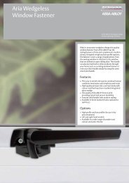
Mason Swim PM12 Pull Handle
mason<br />
About Paul Mason<br />
When you look at a door handle by Paul Mason you see a<br />
product of over three decades of research and development.<br />
The door furniture has emerged as an integral part of his career<br />
as a highly respected sculptor and designer – from the hands<br />
of a versatile master craftsman who has earned an international<br />
reputation for sculptural work with a refined aesthetic sensibility.<br />
Paul’s work as an artist can be found in the collections of public<br />
galleries such as the Auckland Museum and Te Papa<br />
Tongarewa, New Zealand; The Powerhouse Museum, Sydney;<br />
The Renwick, Washington, USA, and in private collections<br />
worldwide. Accolades have included being sent by the Crafts<br />
Council to teach in India in 1979. He taught at Elam School<br />
of Fine Art in the early 1980s and in 1985 was appointed<br />
cultural ambassador by the New Zealand government. He has<br />
received several QEll Arts Council grants and many<br />
commissions, and has exhibited widely, nationally and<br />
internationally. In 1998 he was nominated for the prestigious<br />
Seppelt Contemporary Art Award in Australia.<br />
His work has developed, in both scale and intent, from inspired<br />
pieces of jewellery, inlaid wooden boxes and vessels in metals<br />
and stone to commissions to design furniture and fittings for<br />
many private and public interiors including the National Library<br />
of New Zealand. Paul’s more recent exhibition and<br />
commissioned works have been made of granite and marble,<br />
exploring mass and surface texture, and expressing the<br />
relationship between stone and water.<br />
In the early 1990s Paul designed his first door handle, Samba,<br />
for his own home. It was sculptural and tactile, with more than<br />
a passing aesthetic reference to his minimalist sculptures. Interest<br />
from architects and word of mouth led to development of the<br />
range.<br />
Paul met Graham Chant in 1994 – it was the beginning of a<br />
fruitful partnership. Graham formed Chant Productions in 1996<br />
to bring the Samba and Swim door handles into commercial<br />
production. Over the next two years the Nile, Comma and Rib<br />
suites were introduced to the market.<br />
It is Paul’s interest in sculptural form that is brought into play in<br />
the range of Mason door furniture. The door handles bring art<br />
to the door surface, satisfying the eye and inviting touch. One<br />
can sense the sculptor’s hands defining the sensuous forms<br />
which transcend fashion. That timelessness translates into being<br />
able to complement any interior design statement.<br />
Text by Helen Schamroth<br />
8
Samba Pull Handles<br />
Samba PM00 –1200 Samba PM00–800 Samba PM01 Samba PM02<br />
60<br />
50<br />
mason samba<br />
300<br />
210<br />
250<br />
250<br />
555<br />
170<br />
360<br />
800<br />
55<br />
400<br />
1200<br />
20 60<br />
30<br />
40<br />
80<br />
Example:<br />
Samba PM00 –1200<br />
on a 2400mm<br />
high door<br />
Left hand Samba Pull Handles<br />
shown. All Samba Pull Handles<br />
are available left hand or<br />
right hand.<br />
The PM01 Pull Handle has an<br />
offset of 20mm on the fixing<br />
holes to provide a balanced<br />
vertical visual alignment,<br />
particularly when they are<br />
mounted in pairs on double<br />
doors.<br />
46 54<br />
80<br />
Note: One pair of Samba PM00–1200 Pull Handles<br />
weigh approximately 18kg. Please ensure door and<br />
structure are sufficently strong to support this added weight.<br />
Available in standard mounting options.<br />
10<br />
If the Samba PM00 –1200 and 800 Pull Handles are being<br />
used on glass doors, 12mm holes are required. Mounting bolts<br />
are M8 (8mm diameter).<br />
refer <strong>chant</strong> refer Mason<br />
Product Finishes Escutcheons<br />
4 – 5 26 – 27<br />
refer Mason<br />
Lever Handles<br />
28 – 29<br />
refer <strong>chant</strong><br />
Technical<br />
104 – 113
Samba PM02<br />
Samba PM01<br />
11
Swim Pull Handles<br />
Swim PM09<br />
Swim PM10 Swim PM11 Swim PM12<br />
150<br />
100<br />
60<br />
45<br />
mason swim<br />
350<br />
600<br />
250<br />
410<br />
10<br />
150 290<br />
60<br />
Swim PM13<br />
600<br />
1000<br />
20<br />
65<br />
20<br />
100 170<br />
25<br />
Example:<br />
Swim PM09<br />
on a 2400mm<br />
high door<br />
70<br />
PM09 – PM12 Pull Handles:<br />
The offset of the fixing holes on these<br />
handles provide a balanced vertical<br />
visual alignment, particularly when they<br />
are mounted in pairs on double doors.<br />
Left hand Swim Pull Handles shown. All Swim Pull Handles are<br />
available left hand or right hand.<br />
55<br />
Note: One pair of Swim PM09 Pull Handles weigh<br />
approximately 16kg. Please ensure the door and structure are<br />
sufficently strong to support this added weight.<br />
Available in standard mounting options.<br />
30 40 26<br />
80<br />
If the Swim PM09 or PM10 Pull Handles are being used on<br />
glass doors, 12mm holes are required. Mounting bolts are<br />
M8 (8mm diameter).<br />
Swim Lever Handle/Fixed Handle<br />
Swim Door Knocker<br />
Swim PM14<br />
Swim PM15<br />
Swim PM15S<br />
Swim PM19<br />
63<br />
63<br />
56<br />
170 160 140<br />
170<br />
63 63<br />
57<br />
35<br />
65<br />
Swim Cabinet Handles<br />
Left hand handles shown.<br />
All pull and lever handles are<br />
available left hand or right hand.<br />
Swim PM16 Swim PM17 Swim PM18<br />
12<br />
20<br />
32<br />
95<br />
30 30<br />
20<br />
32<br />
95<br />
refer <strong>chant</strong> refer Mason<br />
Product Finishes Escutcheons<br />
4 – 5 26 – 27<br />
refer Mason<br />
Lever Handles<br />
28 – 29<br />
refer <strong>chant</strong><br />
Technical<br />
104 – 113
Swim PM16<br />
Swim PM14<br />
Swim PM12<br />
13
Nile Pull Handles<br />
Nile PM20 –1000 Nile PM20–750 Nile PM21<br />
Nile PM22 Nile PM23<br />
120<br />
90<br />
60<br />
40<br />
200<br />
30<br />
110<br />
200<br />
mason nile<br />
510<br />
300<br />
340<br />
54<br />
750 450<br />
600<br />
60<br />
1000<br />
72<br />
Nile Pull Handles are non-handed<br />
Nile Lever Handles are reversible.<br />
80<br />
Example:<br />
Nile PM20 –1000<br />
on a 2400mm<br />
high door<br />
Note: One pair of Nile<br />
PM20 –1000 Pull Handles weigh<br />
14kg. Please ensure the door and<br />
structure are sufficently strong to<br />
support this added weight.<br />
Available in standard mounting<br />
options.<br />
If the Nile PM20 –1000 or<br />
PM20 –750 Pull Handles are<br />
being used on glass doors,<br />
12mm holes are required.<br />
Mounting bolts are M8 (8mm<br />
diameter).<br />
90<br />
Nile Lever Handle/Fixed Handle<br />
Nile PM24 Nile PM25 Nile PM26 Nile PM28<br />
Nile Door Knocker<br />
60<br />
12<br />
60<br />
60<br />
160 160<br />
140<br />
170<br />
63<br />
63<br />
57<br />
35<br />
65<br />
Nile Cabinet Handle<br />
Nile PM29<br />
10<br />
14<br />
90<br />
50<br />
30<br />
refer <strong>chant</strong><br />
Product Finishes<br />
4 – 5<br />
refer Mason<br />
Escutcheons<br />
26 – 27<br />
refer Mason<br />
Lever Handles<br />
28 – 29<br />
refer <strong>chant</strong><br />
Technical<br />
104 – 113
Nile PM29<br />
Nile PM25<br />
Nile PM22<br />
15
Comma Pull Handles<br />
Comma PM31<br />
Comma PM32<br />
Comma PM33<br />
Comma PM36<br />
25<br />
25<br />
23<br />
16<br />
mason comma<br />
350<br />
480<br />
250<br />
360<br />
55<br />
10<br />
150<br />
50<br />
240<br />
42<br />
110 160<br />
50<br />
15<br />
25<br />
100 60<br />
80 60<br />
Comma Lever Handle/Fixed Handle<br />
Comma PM34<br />
Comma PM35<br />
Left hand Comma Pull Handles shown.<br />
All Comma Pull Handles are available left hand or right hand.<br />
58<br />
55<br />
Comma Lever Handles are not handed and are reversible.<br />
175<br />
145<br />
63<br />
57<br />
Comma Cabinet Handles<br />
Comma PM37<br />
Comma PM38<br />
96<br />
114<br />
24<br />
28<br />
16<br />
refer <strong>chant</strong><br />
Product Finishes<br />
4 – 5<br />
refer Mason<br />
Escutcheons<br />
26 – 27<br />
refer Mason<br />
Lever Handles<br />
28 – 29<br />
refer <strong>chant</strong><br />
Technical<br />
104 – 113
Comma PM37<br />
Comma PM34<br />
Comma PM32<br />
17
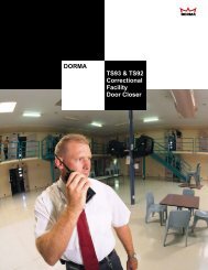
Mason Nile PM24 Lever Handle
Rib Pull Handles<br />
Rib PM41 Rib PM42 Rib PM43<br />
Rib PM46<br />
25<br />
25<br />
20<br />
17<br />
154<br />
100<br />
250<br />
240<br />
170<br />
mason rib<br />
480<br />
350<br />
360<br />
29<br />
55<br />
26<br />
43<br />
30<br />
65<br />
31<br />
75<br />
Rib Lever Handle/Fixed Handle<br />
Rib PM44<br />
Rib PM45<br />
Rib Pull Handles are non-handed.<br />
The Rib Lever Handles are reversible.<br />
54<br />
54<br />
170 145<br />
63<br />
57<br />
Rib Cabinet Handles<br />
Rib PM48<br />
Rib PM49<br />
96<br />
110<br />
160<br />
174<br />
12<br />
22<br />
12<br />
27<br />
20<br />
refer <strong>chant</strong><br />
Product Finishes<br />
4 – 5<br />
refer Mason<br />
Escutcheons<br />
26 – 27<br />
refer Mason<br />
Lever Handles<br />
28 – 29<br />
refer <strong>chant</strong><br />
Technical<br />
104 – 113
Rib PM48<br />
Rib PM44<br />
Rib PM42<br />
21
River Pull Handles<br />
River PM50<br />
River PM51<br />
River PM52<br />
River PM53<br />
87<br />
190<br />
185<br />
150<br />
mason river<br />
250<br />
620<br />
200 500<br />
200 375<br />
520<br />
900<br />
34<br />
53<br />
36<br />
58<br />
38<br />
60<br />
Example:<br />
River PM50<br />
on a 2400mm<br />
high door<br />
River Pull Handles are non-handed.<br />
The River Lever Handle is reversible.<br />
Available in standard mounting<br />
options.<br />
If the River PM50 Pull Handles are<br />
being used on glass doors, a<br />
12mm hole is required. Mounting<br />
bolts are M8 (8mm diameter).<br />
40<br />
63<br />
River Lever Handle<br />
River PM54<br />
60<br />
160<br />
63<br />
22<br />
refer <strong>chant</strong> refer Mason<br />
Product Finishes Escutcheons<br />
4 – 5 26 – 27<br />
refer Mason<br />
Lever Handles<br />
28 – 29<br />
refer <strong>chant</strong><br />
Technical<br />
104 – 113
River PM54<br />
River PM51<br />
23
Flute Pull and Cabinet Handles<br />
Flute PM61 Flute PM62 Flute PM63<br />
centres<br />
centres<br />
mason flute<br />
centres<br />
17<br />
46<br />
12.5<br />
38<br />
22<br />
54<br />
Flute PM61 / PM62 / PM63<br />
Pull Handles<br />
Sizes available (centres specified in mm):<br />
PM61: 300/450/600<br />
PM62: 200/300/450<br />
PM63: 128/160/192/224/256<br />
Flute Lever Handle<br />
Flute PM64<br />
Flute Handles are non-handed.<br />
The Flute Lever Handle is reversible.<br />
50<br />
160<br />
63<br />
17<br />
24<br />
refer <strong>chant</strong> refer Mason<br />
Product Finishes Escutcheons<br />
4 – 5 26 – 27<br />
refer Mason<br />
Lever Handles<br />
28 – 29<br />
refer <strong>chant</strong><br />
Technical<br />
104 – 113
Flute PM64<br />
Flute PM63<br />
Flute PM61<br />
25
Mason Escutcheons<br />
mason escutcheons<br />
PM100 Cylinder Escutcheon<br />
Use with Legge 990 MF Series, Lockwood 3500 Series, Astra<br />
mortice locks (Australasia) and Union (UK). Requires a minimum<br />
lock cylinder projection beyond the door surface of 14mm. The<br />
maximum door thickness with standard length cylinders is<br />
46mm. For thicker doors use extended cylinders or PM103<br />
Cylinder Escutcheon.<br />
For Union 2041 mortice lock with standard double cylinder,<br />
maximum door thickness is 35mm, or 53mm with extended<br />
double cylinder. Fastened with a socket set-screw on the<br />
underside. To specify: PM100/Finish.<br />
PM101 Turn Escutcheon<br />
The turn mechanism is fastened to the door with screws, then<br />
concealed by a ‘screw-on’ cover. Key bars to suit locks as<br />
detailed.<br />
A – 6mm x 2mm bar for Legge 990 MF Series and<br />
Lockwood 3500 Series mortice locks. (Australasia)<br />
B – 3/16” square spindle for Yale 4600, 8600 and<br />
8700, and Schlage L Series mortice locks (USA)<br />
C – 4.5mm square spindle<br />
D – 7.0mm square spindle<br />
E – 7.6mm square spindle<br />
F – 8.0mm square spindle<br />
G – 5.0mm square spindle<br />
H – 6.0mm square spindle<br />
These spindles have a 2mm<br />
flat extension bar when<br />
ordered with PM102<br />
Emergency Turn. Add suffix<br />
ET to order code e.g. To<br />
specify: PM101/Finish/ET<br />
J – 3/16” square spindle on the diamond ( ) for<br />
Accurate Locks (USA)<br />
K – 10mm x 3mm recess to suit <strong>chant</strong> Profile Cylinder Turn<br />
Adaptor 1241 etc.<br />
To specify: PM101/A, B, etc/Finish<br />
PM102 Emergency Turn Escutcheon<br />
The turn mechanism is fastened to the door with screws, then<br />
concealed by a ‘screw-on’ cover. The turn is operated by the<br />
key bar on PM101 Turn Escutcheon above.<br />
To specify: PM102/Finish<br />
PM102i Emergency Turn/Indicator Escutcheon<br />
The turn mechanism is fastened to the door with screws, then<br />
concealed by a ‘screw-on’ cover. The turn is operated by the<br />
key bar on PM101 Turn Escutcheon above.<br />
The red and green colour indicator behind the turn button shows<br />
the lock status.<br />
To specify: PM102i/Finish<br />
PM103 Cylinder Escutcheon<br />
Use with Union 2241 mortice lock where there is insufficient<br />
distance between the cylinder and lever rose for the PM100<br />
Escutcheon. Doors thicker than 50mm will require an extended<br />
cylinder. Fastened with socket set-screw on the underside.<br />
To specify: PM103/Finish<br />
PM105 Profile Cylinder Escutcheon<br />
Use with all profile cylinders. The radiused edge of this<br />
escutcheon complements the domed lever handle rose. Used<br />
when there is limited distance between cylinder length and door<br />
thickness.<br />
To specify: PM105/Finish<br />
PM106A and PM106B<br />
Recessed Cylinder Rings<br />
PM106 A X = 5mm (3/16”)<br />
PM106 B X = 6.5mm (1/4”)<br />
For Yale, Schlage etc cylinders.<br />
To specify: PM106A or B/Finish<br />
PM107A Pull/Turn<br />
For Legge 990 Series Mortice Locks<br />
PM107B Pull/Turn<br />
For SAB Profile Cylinder Mortice Locks<br />
Pull turns are fitted on the inside of entrance doors to withdraw<br />
the latch bolt, when key entry is used on the outside.<br />
The turn base is securely fastened to an adaptor plate which is<br />
fixed to the side of the lock case prior to installation in the door.<br />
Depending on the lock used, specify the spindle bar type<br />
required from the chart opposite for turn escutcheons: typically<br />
A, E or F. Refer to page 113 for an exploded view of the<br />
fastening of the Pull Turn to the lock.<br />
To specify: PM107A or B/Finish<br />
PM108 Profile Cylinder Escutcheon<br />
Use with all profile cylinders. The domed style of this escutcheon<br />
complements the domed lever handle rose. This requires a<br />
cylinder barrel of minimum 26mm more than the thickness of the<br />
door. Fastened with socket set-screw on the underside.<br />
To specify: PM108/Finish<br />
PM109A Privacy Bolt/Turn Assembly<br />
This includes a 60mm backset privacy bolt, PM101 Turn<br />
Escutcheon and PM102 Emergency Turn Escutcheon.<br />
To specify: PM109/Finish<br />
PM109B Privacy Bolt/Turn Assembly with<br />
Indicating Emergency Escutcheon<br />
This includes a 60mm backset privacy bolt, PM101 Turn<br />
Escutcheon and PM102i Emergency Turn/Indicator<br />
Escutcheon.<br />
To specify: PM109B/Finish<br />
30<br />
X<br />
44<br />
26<br />
PM104 Profile Cylinder Escutcheon<br />
Use with all profile cylinders, particularly with locks where there<br />
is insufficient distance between the cylinder and lever rose to<br />
use the PM105 Cylinder Escutcheon. Fastened with a socket<br />
set-screw on the underside.<br />
To specify: PM104/Finish<br />
refer <strong>chant</strong><br />
Product Finishes<br />
4 – 5
PM100<br />
PM104<br />
PM101<br />
PM105<br />
PM102<br />
PM107<br />
PM102i<br />
PM108<br />
PM103<br />
27
Mason Lever Handles on Rose<br />
mason lever handles<br />
Lever Handles PM24, PM25, PM26, PM34, PM35, PM44,<br />
PM45, PM54 and PM64 on rose are symmetrical handles,<br />
and can easily be reversed on site to suit the door handing, by<br />
removing a stop-screw and key, rotating the handle and<br />
replacing the key and stop-screw.<br />
The PM14, PM15 and PM15S handles, which are not<br />
symmetrical, must be ordered to the correct handing required.<br />
Unless otherwise specified, all lever handles have<br />
a return spring within the rose for positive handle return.<br />
Fixing Centre/Rose Types for PM14, PM15,<br />
PM24, PM25, PM34, PM44, PM54, PM64<br />
Lever Handles<br />
Type A – 50.8mm centres at 45º for:<br />
– Tubular latches, 60mm backset or longer<br />
– Legge 990 MF Series and Lockwood 3500 Series<br />
Mortice Locks<br />
Type B – 39.5mm centres, horizontal for:<br />
– Profile Cylinder Mortice Locks:<br />
• AGB, CES, <strong>chant</strong>, CISA, Dorma, FSB, GSV, Häfele,<br />
JADO, KFV, SAB<br />
• Legge 8762, 57mm backset<br />
– Oval Cylinder Mortice Locks:<br />
• Astra Brass and Astra S Series<br />
• Legge 990 MF<br />
• Union 2041, 127mm backset (has the lock cylinder<br />
horizontally in line with the lever handle)<br />
• Union 2241, 57mm and 82.5mm backsets<br />
– Mortice Latch: Union 2677, 57mm backset<br />
– Tubular Latch: Dalco 12002<br />
Fixing Centre/Rose Types for PM15S, PM26,<br />
PM35, PM45 Handles<br />
Type H – 38mm centres, horizontal for:<br />
– Profile Cylinder Mortice Locks:<br />
• AGB, CES, <strong>chant</strong>, CISA, Dorma, FSB, GSV, Häfele,<br />
JADO, KFV, SAB<br />
• Legge 8762, Imperial G7000, 57mm backset, etc<br />
– Oval Cylinder Mortice Locks:<br />
• Astra Brass and Astra S Series<br />
• Legge 990 MF<br />
• Union 2041, 127mm backset (has the lock cylinder<br />
horizontally in line with the lever handle)<br />
• Union 2241, 57mm and 82.5mm backsets<br />
– Mortice Latch : Union 2677, 57mm backset<br />
– Tubular Latch : Dalco 12002<br />
Type I – 38mm centres, vertical for:<br />
Tubular latches, 60mm backset or longer<br />
Type J – 41mm centres, horizontal for:<br />
Lockwood 3500 Series Mortice Locks (Australia)<br />
Type K – 41mm centres, vertical for:<br />
– Tubular latches, 60mm backset or longer<br />
– NT Falcon Mortice Lock (USA)<br />
Example and specification of an order for lever or fixed handles<br />
on rose: (example)<br />
Handle Rose Handing Lever (L) or Finish Quantity<br />
Style Type Fixed (F)<br />
PM24 A LH L SCPV 2pr<br />
It is recommended that the lock type is stated when ordering<br />
handles. Handle bosses are broached 8.1mm to suit the spindle.<br />
Type C – 39.5mm centres, vertical for:<br />
– Tubular latches, 60mm backset or longer<br />
– NT Falcon Mortice Lock (USA)<br />
Type D – 39.5mm centres at 56º for:<br />
– Yale 4600, 8600, 8700 Series Mortice Locks (USA)<br />
Type E – 39.5mm centres at 45º for:<br />
– Schlage L Series Mortice Locks (USA)<br />
Type F – 38mm centres, unsprung rose with tie-screw fixing<br />
between the roses for:<br />
– GSV Locks, 3201Z, 3211Z, 3212Z, 3801Z Mortice Locks<br />
3234 Mortice Latch<br />
Type G – 38mm centres, with unsprung roses. The mounting<br />
bases are tie-screw fixed through the door and lock, covered<br />
with the roses to provide concealed fixing, then the handles are<br />
fixed to the spindle on each side of the door for:<br />
– Profile cylinder mortice locks that have 38mm horizontal fixing<br />
centres and strong return springs to support the lever handle.<br />
• BKS, CES, Dorma, FSB, Häfele<br />
Fixing<br />
All roses have tie-screw fixing to suit the latches and locks as<br />
detailed. Concealed-fixing on the outside rose, visible-fixing on<br />
the inside rose, 5/32” BSW x 3” (76mm) stainless steel screws<br />
supplied as standard. Suitable for doors to 60mm thick.<br />
Fixing Centre/Rose Types for Fixed Handles<br />
A lock plate is assembled into the rose to prevent the handle<br />
from turning.<br />
Type A – 50.8mm centres at 45º<br />
Type C – 39.5mm centres vertical<br />
Type I – 38mm centres, vertical for handles with<br />
57mm diameter roses.<br />
Blank Roses<br />
Used for fixing half sets of lever or fixed handles to a door.<br />
PM110 External: Universal – Threaded 5/32” BSW at<br />
39.5mm and 50.8mm fixing centres<br />
PM111 Internal: Drilled at 39.5mm fixing centres for<br />
countersunk screws<br />
PM112 Internal: Drilled at 50.8mm fixing centres for<br />
countersunk screws<br />
28<br />
refer <strong>chant</strong><br />
Product Finishes<br />
4 – 5<br />
refer <strong>chant</strong><br />
Technical<br />
104 – 113<br />
63<br />
PM110 PM111 PM112
For information on Mason Lever Handles on<br />
Plates, refer to pages 106 to 109<br />
Comma PM35 on A3-51 plate<br />
Nile PM25 on A1-21 plate<br />
Rib PM44 on A3-10 plate 29
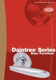
Mason River PM51 Pull Handle
<strong>chant</strong><br />
More about <strong>chant</strong><br />
<strong>chant</strong> is a manufacturer of exclusive hardware for residential,<br />
commercial and marine applications.<br />
Custom designs, finishes and variations to existing products are<br />
also part of the <strong>chant</strong> offering, providing solutions for<br />
architects and developers where standard products do not fit<br />
on-site requirements.<br />
The manufacturing team, artisans in their own right, and the<br />
suppliers to the company, all contribute to the creation of these<br />
unique products from New Zealand.<br />
Our hardware is sought after by architects, developers and<br />
owners of exclusive residential and commercial properties and<br />
has been the preferred choice of internationally recognised<br />
hotels such as the Fairmont in Dubai, Regency Parkway in the<br />
Philippines and the Orchard Scott in Singapore.<br />
The <strong>chant</strong> products on the folllowing pages are beautifully<br />
designed, functional, precision-engineered and very much<br />
‘in touch’ with contemporary architecture and interior design.<br />
32
Bow Pull Handles<br />
Bow 501<br />
Bow 502<br />
Bow 503<br />
Bow 504<br />
180 125<br />
<strong>chant</strong> bow<br />
530 400<br />
415 300<br />
285 200<br />
30<br />
15<br />
62<br />
30<br />
12<br />
56<br />
38<br />
16<br />
68<br />
18<br />
48<br />
74<br />
Bow Lever Handle<br />
Bow 511 A3-10 Bow 511-S<br />
65<br />
65<br />
Bow 511-F or R<br />
65<br />
Bow Pull Handles are symmetrical and ‘non’-handed.<br />
They are suitable for narrow stile and standard doors.<br />
Bow Lever Handle is not handed and is reversible on roses and<br />
44mm wide plates.<br />
132<br />
145<br />
145<br />
112<br />
57<br />
57<br />
34<br />
refer <strong>chant</strong><br />
Product Finishes<br />
4 – 5<br />
refer <strong>chant</strong><br />
Escutcheons<br />
68 – 69<br />
refer Casement refer <strong>chant</strong><br />
Fasteners Technical<br />
88 – 89 104 – 113
Bow 504 Bow 511-F<br />
Bow 502 35
Sabre Pull Handles<br />
Sabre 521 Sabre 522<br />
Sabre 523<br />
Sabre 524<br />
23 20<br />
17 14<br />
150<br />
125<br />
<strong>chant</strong> sabre<br />
590<br />
550<br />
433<br />
400<br />
280<br />
43<br />
17<br />
250<br />
52<br />
30<br />
14<br />
50<br />
23<br />
60<br />
53<br />
23<br />
70<br />
55<br />
Sabre Lever Handle<br />
Sabre 531 A3-10 Sabre 531-S<br />
60<br />
60<br />
Sabre 531-F or R<br />
60<br />
Sabre Pull Handles are ‘handed’ and suitable for narrow stile<br />
and standard doors. Left hand handles shown.<br />
Sabre Lever Handle is not handed and is reversible on roses<br />
and 44mm wide plates.<br />
132<br />
145<br />
145<br />
112<br />
57<br />
57<br />
36<br />
refer <strong>chant</strong><br />
Product Finishes<br />
4 – 5<br />
refer <strong>chant</strong><br />
Escutcheons<br />
68 – 69<br />
refer Casement<br />
Fasteners<br />
88 – 89<br />
refer <strong>chant</strong><br />
Technical<br />
104 – 113
Sabre 524 Sabre 531-F<br />
Sabre 522 37
Arc Pull Handles<br />
Arc 541<br />
Arc 542<br />
Arc 543<br />
Arc 544<br />
155 125<br />
285 250<br />
<strong>chant</strong> arc<br />
590 550<br />
440 400<br />
27<br />
15<br />
53<br />
17<br />
43<br />
60<br />
20<br />
55<br />
63<br />
20<br />
70<br />
65<br />
Arc Lever Handle<br />
Arc 551 A3-10 Arc 551-S Arc 551-F or R<br />
60<br />
60<br />
60<br />
Arc Pull Handles are symmetrical and ‘non-handed’. They are<br />
suitable for narrow stile and standard doors.<br />
Arc Lever Handle is not handed and is reversible on roses and<br />
44mm wide plates.<br />
132<br />
145<br />
145<br />
112<br />
57<br />
57<br />
38<br />
refer <strong>chant</strong><br />
Product Finishes<br />
4 – 5<br />
refer <strong>chant</strong><br />
Escutcheons<br />
68 – 69<br />
refer Casement<br />
Fasteners<br />
88 – 89<br />
refer <strong>chant</strong><br />
Technical<br />
104 – 113
Arc 544 Arc 551-F<br />
Arc 542<br />
39
Luna Pull Handles<br />
Luna 561<br />
Luna 562<br />
Luna 563<br />
Luna 564<br />
88<br />
rad.<br />
125<br />
<strong>chant</strong> luna<br />
390<br />
radius<br />
500<br />
470<br />
300<br />
radius<br />
400<br />
305<br />
180<br />
radius<br />
250<br />
160<br />
38<br />
12<br />
50<br />
580<br />
15<br />
65<br />
57<br />
15<br />
95<br />
65<br />
16<br />
110<br />
68<br />
Luna Lever Handle<br />
Luna 571 A3-10 Luna 571-S Luna 571-F or R<br />
65<br />
65<br />
65<br />
Luna Pull Handles are symmetrical and ‘non-handed’. They are<br />
suitable for narrow stile and standard doors.<br />
Luna Lever Handle is not handed and is reversible on roses and<br />
44mm wide plates.<br />
132<br />
145<br />
145<br />
112<br />
57<br />
57<br />
40<br />
refer <strong>chant</strong><br />
Product Finishes<br />
4 – 5<br />
refer <strong>chant</strong><br />
Escutcheons<br />
68 – 69<br />
refer Casement<br />
Fasteners<br />
88 – 89<br />
refer <strong>chant</strong><br />
Technical<br />
104 – 113
Luna 564 Luna 571-R<br />
Luna 562<br />
41
<strong>chant</strong> Delta 631 Lever Handle
Cobra Pull Handles<br />
Cobra 600<br />
Cobra 601<br />
Cobra 602<br />
Cobra 603<br />
22<br />
16<br />
15<br />
14<br />
<strong>chant</strong> cobra<br />
565 400<br />
400 300<br />
270<br />
200<br />
40<br />
65<br />
42<br />
70<br />
1000<br />
700<br />
Cobra Pull and Lever Handles are ‘non-handed’.<br />
Cobra Lever Handle is reversible on roses and<br />
44mm wide plates.<br />
45<br />
75<br />
Example:<br />
Cobra 600<br />
on a 2400mm<br />
high door<br />
Cobra 604<br />
14<br />
Cobra 605<br />
12<br />
180<br />
125<br />
140<br />
10 0<br />
28<br />
55<br />
34<br />
60<br />
50<br />
100<br />
Note: One pair of Cobra 600 Pull Handles<br />
weigh approximately 16kg. Please ensure the<br />
door and structure are sufficently strong to<br />
support this added weight.<br />
Cobra Door Knocker<br />
Cobra 609<br />
Available in standard mounting options.<br />
180<br />
If the Cobra 600 Pull Handles are being used<br />
on glass doors, a 12mm hole is required.<br />
Mounting bolts are M8 (8mm diameter).<br />
35<br />
65<br />
Cobra Lever Handles<br />
Cobra Cabinet Handle<br />
Cobra 610-S Cobra 611-F Cobra 611-R<br />
Cobra 606<br />
65 60<br />
60<br />
100 64<br />
160<br />
140<br />
140<br />
28<br />
35<br />
57<br />
57<br />
57<br />
44<br />
Both Cobra 610 and 611 lever handles<br />
can accommodate F, R or S rose types<br />
refer <strong>chant</strong><br />
Product Finishes<br />
4 – 5<br />
refer <strong>chant</strong><br />
Escutcheons<br />
68 – 69<br />
refer Casement<br />
Fasteners<br />
88 – 89<br />
refer <strong>chant</strong><br />
Technical<br />
104 – 113
Cobra 604 Cobra 611-F<br />
Cobra 602<br />
45
Delta Pull and Cabinet Handles<br />
Delta 620<br />
Delta 621<br />
Delta 622<br />
Delta 623<br />
Delta 624<br />
Delta 625<br />
200<br />
<strong>chant</strong> delta<br />
550 400<br />
450 350<br />
400 300<br />
300 200<br />
250 175<br />
25<br />
45<br />
32<br />
50<br />
32<br />
50<br />
Delta 626<br />
Delta 627<br />
* 25<br />
38<br />
58<br />
1200<br />
800<br />
38 58<br />
*Offset pillar dimensions.<br />
25mm offset pillars<br />
available on 621, 622,<br />
623 and 624 handles<br />
200 150<br />
150 125<br />
25<br />
45<br />
25<br />
45<br />
38 57<br />
Example:<br />
Delta 620<br />
on a 2400mm<br />
high door<br />
Delta Pull Handles are ‘handed’ left and right, because of their<br />
offset asymmetrical triangular form. They are suitable for<br />
standard doors and wide stile doors with standard pillars.<br />
For narrow stile doors, specify offset pillars to provide finger<br />
clearance between the handle and door edge or frame<br />
backstop, add sufffix “OS” to the order code.<br />
Non Standard Lengths<br />
All Delta pull handles in 25mm, 32mm and 38mm<br />
section widths can be produced in the “plated finishes” and<br />
PBU to special lengths, in multiples of 100mm.<br />
Section width Maximum length<br />
38mm<br />
1200mm<br />
32mm<br />
800mm<br />
25mm<br />
600mm<br />
Left hand handles shown. All handles can be produced without<br />
the thumb recess if required.<br />
Delta Lever Handle<br />
Delta 631 A1-10<br />
Delta 631-S<br />
Delta 631-F<br />
To specify special lengths, state:<br />
A: Handle section width 25mm, 32mm or 38mm.<br />
B: Overall length.<br />
C: Mounting pillar centres.<br />
D: Distance from the top of the handle to the top of the thumb<br />
recess.<br />
E: Length of the thumb recess.(Note:Thumb recess can be<br />
deleted).<br />
F: Handing: Left-hand (LH) or Right-hand (RH).<br />
Example of specification:<br />
51<br />
51<br />
51<br />
A B C D E F<br />
142<br />
153<br />
153<br />
Delta 32mm 800mm 600mm 125mm 60mm LH<br />
/Mounting option/Finish/Quantity<br />
46<br />
112<br />
57<br />
57<br />
refer <strong>chant</strong><br />
Product Finishes<br />
4 – 5<br />
refer <strong>chant</strong><br />
Escutcheons<br />
68 – 69<br />
refer Casement<br />
Fasteners<br />
88 – 89<br />
refer <strong>chant</strong><br />
Technical<br />
104 – 113
Delta 631 on A1-10 Plate<br />
Delta 623 on standard pillars<br />
Delta 622 on offset pillars 47
Swan 651 Lever Handle<br />
The Swan Lever Handle is a variation of a classic design with<br />
simple flowing curves to complement more traditional decor.<br />
They are a ‘handed’ handle and are suitable for narrow stile<br />
and standard doors.<br />
<strong>chant</strong> swan<br />
63<br />
125<br />
Refer Groups 10 – 170 Plates on<br />
Technical pages 106 to 108.<br />
Example shown:<br />
Swan 651 A3-111<br />
220<br />
38<br />
(or 32)<br />
63<br />
125<br />
Refer Groups 210 – 310 Plates on<br />
Technical pages 106 and 109.<br />
Example shown:<br />
Swan 651 A3-211<br />
165<br />
44<br />
63<br />
125<br />
Swan 651 on Rose type 38R<br />
The following options are<br />
detailed on page 105:<br />
38F/38R/38S<br />
41F/41R/41S<br />
57<br />
48<br />
refer <strong>chant</strong><br />
Product Finishes<br />
4 – 5<br />
refer <strong>chant</strong><br />
Escutcheons<br />
68 – 69<br />
refer Casement<br />
Fasteners<br />
88 – 89<br />
refer <strong>chant</strong><br />
Technical<br />
104 – 113
Swan 651 on A3-211 plate<br />
Swan 651 on 38-R rose<br />
Swan 651 on A3-111 plate<br />
49
Cubic Pull and Cabinet Handles<br />
Cubic 661<br />
25 x 12.5mm<br />
Cubic 662<br />
25 x 25mm<br />
Cubic 662 Offset (OS)<br />
25 x 25mm<br />
Cubic 663<br />
19 x 19mm<br />
Cubic 664<br />
16 x 16mm<br />
Cubic 665<br />
12.5 x 12.5mm<br />
<strong>chant</strong> cubic<br />
centres<br />
centres<br />
centres<br />
centres<br />
16<br />
centres<br />
50<br />
12.5<br />
centres<br />
42<br />
25<br />
52<br />
25<br />
65<br />
Sizes available (centres specified in mm)<br />
Cubic 661: 300/450/600/800<br />
Cubic 662: 300/450/600/800/1000<br />
Cubic 663: 200/300/450/600<br />
25<br />
65<br />
19<br />
55<br />
Sizes available (centres specified in mm)<br />
Cubic 664: 200/300/450<br />
Cubic 665: 128#/160#/192#/224#/256#/<br />
300/450<br />
#S32 multiples<br />
The Cubic Pull Handles are available with offset (OS) pillars for<br />
Cubic 661 and 662 Handles (refer example shown above).<br />
Cubic Handles are ‘handed’ left and right when fitted with<br />
offset pillars. For narrow stile doors, specify offset pillars to<br />
provide finger clearance between the handle and door edge or<br />
frame backstop, add suffix “OS” to the order code.<br />
A design feature of the Cubic Handles is that they have a<br />
square face with a machined, chamfered form inside the handle<br />
to provide a comfortable touch.<br />
Cubic Towel Rail<br />
Cubic 663 TR (Towel Rail) 19 x 19mm, Y=70<br />
centres<br />
Sizes available (centres specified in mm)<br />
Cubic 663 TR: 450/600/750<br />
Mounting options: Surface-fixed (SF) or Back-fixed (BF)<br />
X<br />
Y<br />
Note:<br />
– Cubic 664 Pull Handles use M5 mounting studs, the larger<br />
sizes use M6 studs.<br />
– Cubic Cabinet Handle 665 is back fixed only with<br />
M4 screws.<br />
– Cubic 663 TR (Towel Rail) mounting options: surface-fixed<br />
with 10g screws, or back-fixed with M6 screws.<br />
Backplate X = 50 x 50mm<br />
– The backplates (X), 50 x 50mm or 38 x 38mm can be<br />
used on all pull handles as an added feature if required.<br />
Specify ‘BP’ and size with the handle order.<br />
– Custom Designs: Cubic Handles with their flat front face<br />
lend themselves to custom machining to create special<br />
effects and designs. Refer to page 101 for an example.<br />
Cubic Lever Handles<br />
Cubic 671-P only Cubic 672-P Cubic 672-F<br />
Contact <strong>chant</strong> with your requirements.<br />
53<br />
56<br />
56<br />
145<br />
145<br />
145<br />
57<br />
57<br />
57<br />
Cubic 671 Lever Handle: 25 x 12.5mm section<br />
Cubic 672 Lever Handle: 19 x 16mm section<br />
50<br />
Both Cubic 671 and 672 can be used with the Pyramid (P) Rose.<br />
The Cubic 672 can also be used with the Facet (F) Rose and<br />
the Square (S) Rose.<br />
Both lever handle styles can be used with any back plates.<br />
refer <strong>chant</strong><br />
Product Finishes<br />
4 – 5<br />
refer <strong>chant</strong><br />
Escutcheons<br />
68 – 69<br />
refer Casement<br />
Fasteners<br />
88 – 89<br />
refer <strong>chant</strong><br />
Technical<br />
104 – 113
Cubic 672-P<br />
Cubic 664<br />
Cubic 662<br />
51
Line Pull and Cabinet Handles<br />
Line 681<br />
Line 682 Line 683<br />
Line 684<br />
<strong>chant</strong> line<br />
centres<br />
centres<br />
centres<br />
centres<br />
12.5<br />
42<br />
75 52<br />
25<br />
52<br />
Sizes available (centres specified in mm)<br />
Line 681: 300/450/600/800<br />
Line 682: 200/300/450/600<br />
Line 683: 128/160/192/224/256/300/450<br />
Line 684: 200/300<br />
19<br />
48<br />
Line 691 on Tall Plates<br />
Tall Plates can be made to suit the lock types in<br />
Groups 20/30/40/50 and 60.<br />
*Specify spindle to cylinder barrel centreline or thumb turn<br />
dimension, eg. 41+46 – 92mm.<br />
To specify: example<br />
Handle Plate Plate Handing Lever (L) or Finish Quantity<br />
Style Style Combination Fixed (F)<br />
Line 691 Tall B1 41+46–92* LH L SCPV 2pr<br />
Line 691 on <strong>chant</strong> Tall Plates<br />
Line Lever Handles<br />
Line 691 on Group 10 Plates<br />
53<br />
112<br />
135<br />
23<br />
*The only handle plate style<br />
used with the Line Lever<br />
Handle is the B1 plate,<br />
32mm wide on pages 106<br />
and 107. They match the soft<br />
edges of the Lever Handle<br />
with a complimentary width.<br />
300<br />
100<br />
*<br />
90<br />
100<br />
X<br />
32<br />
Line 691 on Group 20/30/40 Plates<br />
Overall height X:<br />
Group 20: 216mm<br />
Group 30: 191mm<br />
Group 40: 220mm<br />
Line Door Knocker<br />
LIne Door Knocker 689<br />
170<br />
Line 691 on Group 50/60 Plates<br />
35<br />
30<br />
52<br />
X<br />
Overall height X:<br />
Group 50: 190mm<br />
Group 60: 160mm<br />
refer <strong>chant</strong><br />
Product Finishes<br />
4 – 5<br />
refer <strong>chant</strong><br />
Escutcheons<br />
68 – 69<br />
refer Casement<br />
Fasteners<br />
88 – 89<br />
refer <strong>chant</strong><br />
Technical<br />
104 – 113
Line 684<br />
Line 691<br />
on Tall Plate<br />
Line 683<br />
Line 681<br />
53
<strong>chant</strong> Line 691 Lever Handle on Tall Plate
Line Door Stop<br />
Line Wall Doorstop 3211<br />
Line Floor Doorstop 3212<br />
Line Casement 3951 Line Casement 3952<br />
<strong>chant</strong> line<br />
Line Doorstop 3213<br />
Line Sliding Doorstop 3214<br />
Line 2-Point Lock Lever 3954<br />
Line Escutcheons<br />
Oval Cylinder Escutcheon<br />
3440<br />
Emergency Turn / Indicator Escutcheon<br />
3442i<br />
Turn Escutcheon<br />
3441<br />
Profile Cylinder Escutcheon<br />
3443<br />
Emergency Turn Escutcheon<br />
3442<br />
Pull Turn<br />
3444<br />
56<br />
refer <strong>chant</strong><br />
Product Finishes<br />
4 – 5<br />
refer <strong>chant</strong><br />
Escutcheons<br />
68 – 69<br />
refer Door<br />
Stops<br />
73<br />
refer Casement<br />
Fasteners<br />
88 – 89
Line 3213 Line 3443<br />
Line 3952<br />
57
Angle Pull and Cabinet Handles<br />
Angle 701 Angle 702 Angle 703 Angle Custom<br />
Brass tube or rod is used for electroplated<br />
finishes, e.g.: satin chrome plate velvet,<br />
polished chrome, black chrome,<br />
copper etc.<br />
These handle designs are not suitable for<br />
production in bronze as the base metal.<br />
<strong>chant</strong> angle<br />
600<br />
450<br />
19<br />
300<br />
50<br />
A<br />
B C<br />
Custom Sizes<br />
When custom handles are required,<br />
specify:<br />
A = Hole centres of pillars<br />
B = Diameter of rod<br />
C = Height of handle<br />
D = Finish<br />
32<br />
70<br />
25<br />
60<br />
Angle Towel Rail<br />
Angle 718<br />
4<br />
38<br />
25<br />
80<br />
Angle Lever Handle<br />
Angle 711 on Angle/Rod C Rose Angle 711 A1- 220<br />
20.5<br />
65<br />
65<br />
160<br />
152<br />
715: 1200mm centres<br />
716: 900mm centres<br />
717: 600mm centres<br />
718: 450mm centres<br />
Angle Towel Rail is mounted to the wall with 2 x 8mm<br />
mounting screws fastened into a solid timber stud.<br />
Recommended minimum framing timber thickness to<br />
mount to is 50mm.<br />
57<br />
166<br />
The washers are required to increase the contact area<br />
against the wall and prevent the towel rail from<br />
damaging the surface.<br />
Angle Robe Hook<br />
Angle 709<br />
Angle/Rod Escutcheons<br />
3450 3451 3452<br />
70<br />
32<br />
25<br />
Angle Robe Hook is mounted to the wall with an<br />
8mm mounting screw fastened into a solid<br />
timber stud. Recommended minimum framing timber<br />
thickness to mount to is 50mm.<br />
3452i 3453 3454<br />
58<br />
refer <strong>chant</strong><br />
Product Finishes<br />
4 – 5<br />
refer <strong>chant</strong><br />
Escutcheons<br />
68 – 69<br />
refer Casement<br />
Fasteners<br />
88 – 89<br />
refer <strong>chant</strong><br />
Technical<br />
104 – 113
Angle 711 on C Rose<br />
Angle 717<br />
Angle 701<br />
59
Rod Pull and Cabinet Handles<br />
Rod 721 Rod 722 Rod 723<br />
Materials<br />
Brass rod is used for electroplated finishes, e.g.: satin chrome<br />
plate velvet, polished chrome plate, black chrome plate, etc.<br />
Bronze rod is used for bronze and “Living Finishes”<br />
(refer page 119).<br />
<strong>chant</strong> rod<br />
600<br />
500<br />
400<br />
300<br />
250<br />
22<br />
200<br />
50<br />
The rods are machined with the recess for the pillars to<br />
fasten into.<br />
The Rod Pull and Cabinet Handles can also be made from<br />
316 grade stainless steel, for polished or brushed stainless steel<br />
finishes. Specify either finish option. The handles are generally<br />
made from solid rod for up to 1000mm in length, and<br />
diameters up to 32mm.<br />
25<br />
60<br />
Tubular handles in 316 grade stainless can be produced for<br />
larger sizes. These use an internal nut to fasten the pillars to.<br />
Weight and length details need to be considered for shipping,<br />
and the practicality of plated finishes for larger handles.<br />
Consult <strong>chant</strong> with your requirements.<br />
32<br />
Rod Lever Handle<br />
Rod 731 on Rod/Angle C Rose<br />
60<br />
150<br />
60<br />
Rod 731 A1- 220<br />
16 16<br />
60<br />
A<br />
152<br />
C<br />
B<br />
E<br />
D<br />
Custom Sizes<br />
When custom handles are required, specify:<br />
A = Length<br />
B = Hole centres of pillars<br />
C = Diameter of rod<br />
D = Height of handle<br />
E = Pillar diameter<br />
Standard pillars are 15mm and 19mm diameter (parallel),<br />
and 25mm diameter tapered pillars.<br />
Other variations can be made to order.<br />
F = Number of pillars<br />
A central third pillar may be required on<br />
extra long handles to avoid the handle flexing.<br />
G = Material/Finish<br />
57<br />
166<br />
Rod / Angle Escutcheons<br />
3450 3451 3452<br />
3452i 3453 3454<br />
60<br />
refer <strong>chant</strong><br />
Product Finishes<br />
4 – 5<br />
refer <strong>chant</strong><br />
Escutcheons<br />
68 – 69<br />
refer Casement<br />
Fasteners<br />
88 – 89<br />
refer <strong>chant</strong><br />
Technical<br />
104 – 113
Rod 731 on Rose<br />
Rod 723<br />
Rod 721<br />
61
<strong>chant</strong> stop<br />
Stop 741 Door Knob<br />
Diameter 60mm<br />
Projection 66mm<br />
Stop 742 Door Knob<br />
Diameter 50mm<br />
Projection 63mm<br />
Stop Knobs<br />
A contemporary and versatile range of door and cabinet knobs<br />
suitable for use throughout a project and across a number of<br />
applications. The unique sculptured form is available in all<br />
finishes.<br />
Features<br />
– Finger-recess with a soft contour for user comfort<br />
– Internal spring mechanism ensures positive latch<br />
and knob return<br />
– Large bearing surface provides support for the solid<br />
knob machined from brass or bronze<br />
– Suitable for long back set tubular latches and<br />
mortice locks with 38 or 44mm fixing centres<br />
– Knobs are reversible to aid handing and can be<br />
turned 90 degrees on the base rose to provide<br />
vertical fixing with tubular latches, or horizontal fixing<br />
on mortice locks.<br />
– Knob fastens to the boss by a socket set-screw on the<br />
underside. Removal of the knob allows for<br />
tie-screw fixing through the door.<br />
– This range of door knobs is complemented by the ‘facet’<br />
range of escutcheons 3410 to 3414 on pages 68 and 69.<br />
Stop 745 Dummy Trim<br />
Diameter 60mm<br />
Projection 63mm<br />
Stop 746 Dummy Trim<br />
Diameter 50mm<br />
Projection 50mm<br />
Fixing Centres and Latch/<br />
Lock Types<br />
Stop 741 Door Knob<br />
Fixing Centres:<br />
39.5mm horizontal and vertical and 50.8mm @45 degrees<br />
Lock/Latch Types:<br />
– <strong>chant</strong> mortice locks<br />
– Legge 990 MF Series and Lockwood 3500 Series<br />
mortice locks<br />
– Profile cylinder mortice locks with nominal<br />
38mm centres and light return springs<br />
– Tubular latches – 60mm minimum backset<br />
Stop 742 Door Knob<br />
Fixing Centres:<br />
39.5mm horizontal and vertical<br />
Lock/Latch Types:<br />
– <strong>chant</strong> mortice locks<br />
– Legge 990 MF Series mortice locks<br />
– Profile cylinder mortice locks with nominal<br />
38mm centres and light return springs<br />
– Tubular latches – 60mm minimum backset<br />
Stop 745/746 Dummy Trim<br />
A flanged mounting collar is fastened to the door with two<br />
screws, the knob attached to the mounting collar with a socket<br />
set-screw on the underside.<br />
62
Stop 751 Cabinet Knob<br />
Diameter 35mm<br />
Projection 35mm<br />
Fixing Screw M5<br />
Specifying<br />
To specify (example)<br />
Knob Finish Quantity<br />
742 SCPV 2pr<br />
Stop 751b Cabinet Knob<br />
Diameter 35mm<br />
Projection 38mm<br />
For use with 751 Cabinet<br />
Knob on the opposite side<br />
of the door. The 751 Knob<br />
is fastened to the door with<br />
a mounting collar then the<br />
751b Knob is fastened to<br />
the collar in the correct<br />
alignment. Particularly<br />
suitable for shower doors.<br />
It is recommended that the lock type is stated when<br />
ordering knobsets.<br />
<strong>chant</strong> stop<br />
Stop 752 Cabinet Knob<br />
Diameter 28mm<br />
Projection 30mm<br />
Fixing Screw M5<br />
Stop 753 Cabinet Knob<br />
Diameter 22mm<br />
Projection 25mm<br />
Fixing Screw M5<br />
Cross section of stop knobs<br />
showing contoured finger-recess<br />
A unique detail off these knobs is that the finger recess is<br />
machined in a curved path. This softens the edge at each end<br />
providing a comfortable grip. This detail can be applied to<br />
custom made knobs of a cylindrical style with a flat or radius<br />
end. Contact <strong>chant</strong> to discuss your requirements.<br />
refer <strong>chant</strong><br />
Product Finishes<br />
4 – 5<br />
refer <strong>chant</strong><br />
Escutcheons<br />
68 – 69<br />
refer Door<br />
Stops<br />
73<br />
refer <strong>chant</strong><br />
Technical<br />
104 – 113<br />
63
<strong>chant</strong> round/royal<br />
Round 761 on Mason ‘A’ Rose<br />
Knob Diameter 70mm<br />
Rose Diameter 63mm<br />
Projection<br />
65mm<br />
Round 762 on Mason ‘A’ Rose<br />
Knob Diameter 63mm<br />
Rose Diameter 63mm<br />
Projection<br />
64mm<br />
Round/Royal Knobs<br />
Round Door Knobs and matching Escutcheons are designed for<br />
front doors and applications where a circular knob is required.<br />
This simple, elegant design can be used with a longer backset<br />
latch to become a feature of the door. The ability to separate<br />
the door knob and latch from the deadbolt and matching<br />
escutcheons allows for a variety of combinations to suit individual<br />
requirements.<br />
Features<br />
– Internal spring mechanism ensures positive latch return<br />
– Large bearing surface provides support for the solid knob<br />
– Suitable for long back set tubular latches and mortice locks<br />
– Reversible door knobs aid handing<br />
– Machined from solid brass or bronze<br />
Round 763 on Mason ‘A’ Rose<br />
Knob Diameter 55mm<br />
Rose Diameter 63mm<br />
Projection<br />
62mm<br />
Round 762/763 are available<br />
on the following <strong>chant</strong> rose<br />
types:<br />
38F/38R/38S or<br />
41F/41R/41S<br />
F=Facet/R=Radius/S=Square<br />
Round 762 on <strong>chant</strong> 38R Rose<br />
Knob Diameter 63mm<br />
Rose Diameter 57mm<br />
Projection<br />
64mm<br />
Fixing Centres and<br />
Latch/Lock Types<br />
761/762/763/767 Knobs on<br />
Mason ‘A’ Rose<br />
Fixing Centres:<br />
50.8mm @ 45 degrees, visible fixing on inside rose<br />
Lock/Latch Types:<br />
– Tubular latches, 70mm backset or longer<br />
– <strong>chant</strong> Mortice Lock, 70mm and 90mm backset<br />
With this lock, use Mason PM105, PM108 or<br />
<strong>chant</strong> escutcheons<br />
762/763/767 Knobs on<br />
<strong>chant</strong> 38F/38R/38S Roses<br />
Fixing Centres:<br />
38mm vertical and horizontal, concealed fixing both sides<br />
Lock/Latch Types:<br />
– Profile cylinder mortice locks with nominal 38mm centres,<br />
light return springs and appropriate backset<br />
– <strong>chant</strong> Mortice Lock, 70mm and 90mm backset<br />
With this lock, use <strong>chant</strong> escutcheons<br />
– Tubular latches – 70mm minimum backset recommended<br />
762/763/767 Knobs on<br />
<strong>chant</strong> 41F/41R/41S Roses<br />
Fixing Centres:<br />
41mm vertical and horizontal, concealed fixing both sides<br />
Lock/Latch Types:<br />
– <strong>chant</strong> Mortice Lock, 70mm and 90mm backset<br />
With this lock, use <strong>chant</strong> escutcheons<br />
– Tubular latches – 70mm minimum backset recommended<br />
Spindle size:<br />
– Spindle supplied: 7.6mm or 8mm<br />
– Suitable for full and split spindle applications<br />
64<br />
Round 763 on <strong>chant</strong> 38R Rose<br />
Knob Diameter 55mm<br />
Rose Diameter 57mm<br />
Projection<br />
62mm
Round 763 on 44mm Plate<br />
Diameter<br />
55mm<br />
Plate Width 44mm<br />
Projection<br />
63mm<br />
Refer <strong>chant</strong> Technical to specify<br />
plate type within the following<br />
group:<br />
Group<br />
210<br />
Example shown: A3–211 Plate<br />
Round/Royal Knobs on Plates<br />
Refer <strong>chant</strong> Technical, pages 104 – 113, for plate options<br />
and information on how to create a specification.<br />
<strong>chant</strong> round/royal<br />
Round 763 on 44mm Plate<br />
Diameter<br />
55mm<br />
Plate Width 44mm<br />
Projection<br />
63mm<br />
Refer <strong>chant</strong> Technical to specify<br />
plate type within the following<br />
groups:<br />
Groups<br />
220/230/240/250/310<br />
Example shown: A3–231 Plate<br />
Royal 767 on Mason ‘A’ Rose<br />
Door Knob<br />
Knob Diameter 55mm<br />
Rose Diameter 63mm<br />
Projection<br />
62mm<br />
Royal 767 on <strong>chant</strong><br />
38F/38R/41F/41R Rose<br />
Door Knob<br />
Knob Diameter 55mm<br />
Rose Diameter 57mm<br />
Projection<br />
62mm<br />
refer <strong>chant</strong><br />
Product Finishes<br />
4 – 5<br />
refer Mason<br />
Escutcheons<br />
26 – 27<br />
refer <strong>chant</strong><br />
Escutcheons<br />
68 – 69<br />
refer <strong>chant</strong><br />
Technical<br />
104 – 113<br />
65
<strong>chant</strong> round/royal<br />
Royal 767 on 44mm Plate<br />
Diameter<br />
55mm<br />
Plate Width 44mm<br />
Projection<br />
63mm<br />
Refer <strong>chant</strong> Technical to specify<br />
plate type within the following<br />
groups:<br />
Groups<br />
210/220/230/240/250<br />
Example shown: B4 220 Plate<br />
Royal 767 on 44mm Plate<br />
Diameter<br />
55mm<br />
Plate Width 44mm<br />
Projection<br />
63mm<br />
Example shown: C5 220 Plate<br />
Cylinder Escutcheon<br />
A<br />
Tubular Deadbolts and Latches<br />
Turn Assembly<br />
B<br />
Deadbolt 776 60–70mm<br />
C<br />
Deadbolt 777 127mm<br />
D<br />
Note<br />
Deadbolt Cylinders are 6-pin, C4 profile<br />
Deadbolt Cylinder and Turn – 70mm, 770<br />
includes:<br />
– Cylinder Escutcheon A<br />
– Turn Assembly B<br />
– 60–70mm Backset Deadbolt C<br />
Deadbolt Cylinder and Turn – 127mm, 771<br />
includes:<br />
– Cylinder Escutcheon A<br />
– Turn Assembly B<br />
– 127mm Backset Deadbolt D<br />
Deadbolt Double Cylinder – 70mm, 772<br />
includes:<br />
– 2 x Cylinder Escutcheons A<br />
– 60–70mm Backset Deadbolt C<br />
66<br />
Deadbolt Double Cylinder – 127mm, 773<br />
includes:<br />
– 2 x Cylinder Escutcheons A<br />
– 127mm Backset Deadbolt D
Rebate Packer<br />
E<br />
Rebate Deadbolt Strike<br />
F<br />
Rebate Latch Strike<br />
G<br />
Deadbolt Rebate Kit, 774<br />
includes:<br />
– Rebate Packer E<br />
– Rebate Deadbolt Strike F<br />
Tubular Latch Rebate Kit, 775<br />
includes:<br />
– Rebate Packer E<br />
– Rebate Latch Strike G<br />
Deadbolt, 776<br />
Adjustable 60-70mm backset<br />
Deadbolt, 777<br />
127mm backset<br />
Tubular Latch, 778<br />
70mm backset<br />
Tubular Latch, 779<br />
127mm backset<br />
<strong>chant</strong> round/royal<br />
Tubular Latch 778<br />
70mm Backset<br />
Product Finishes<br />
Finishes Available for Strikes:<br />
Stainless Steel<br />
SS<br />
Bronze Plate*<br />
BP<br />
Copper Plate<br />
COP<br />
*This is a brass/bronze plated finish on stainless steel as an<br />
approximate match for bronze.<br />
Tubular Latch 779<br />
127mm Backset<br />
Finishes Available for Door Knobs, Cylinder Escutcheon,<br />
Turn Assembly and Rebate Packer: refer to Product Finishes<br />
page 4 – 5<br />
refer <strong>chant</strong><br />
Product Finishes<br />
4 – 5<br />
refer Mason<br />
Escutcheons<br />
26 – 27<br />
refer <strong>chant</strong><br />
Escutcheons<br />
68 – 69<br />
refer <strong>chant</strong><br />
Technical<br />
104 – 113<br />
67
<strong>chant</strong> Escutcheons<br />
<strong>chant</strong> escutcheons<br />
Oval Cylinder Escutcheons<br />
3400/3410/3420/3430/3440/3450<br />
Use with Legge 990 MF Series, Lockwood 3500 Series,<br />
Astra mortice locks (Australasia), and Union (UK).<br />
Maximum door thickness with standard length cylinders<br />
3400/3440/3450 escutcheon 56mm<br />
3410/3420/3430 escutcheon 52mm<br />
Fastened with socket set-screw on the underside.<br />
To specify:3400/3410/3420/3430/3440/3450/Finish.<br />
Profile Cylinder Escutcheons<br />
3403/3413/3423/3433/3443/3453<br />
Use with all profile cylinder mortice locks.<br />
Maximum door thickness<br />
3403/3443/3453 escutcheon with 5 pin cylinder 46mm<br />
3403/3443/3453 escutcheon with 6 pin cylinder 54mm<br />
3413/3423/3433 escutcheon with 5 pin cylinder 42mm<br />
3413/3423/3433 escutcheon with 6 pin cylinder 50mm<br />
Fastened with socket set screw on the underside.<br />
To specify: 3403/3413/3423/3433/3443/3453/Finish<br />
Turn Escutcheons<br />
3401/3411/3421/3431/3441/3451<br />
The turn mechanism is fastened to the door with screws,<br />
then concealed by either a ‘screw-on’ round style cover or a<br />
socket set screw on the underside of the square style covers.<br />
Key bars to suit locks as detailed.<br />
A – 6mm x 2mm bar for Legge 990 MF Series and<br />
Lockwood 3500 Series mortice locks. (Australasia)<br />
B – 3/16” square spindle for Yale 4600, 8600 and 8700,<br />
and Schlage L Series mortice locks (USA)<br />
C – 4.5mm square spindle<br />
D – 7.0mm square spindle<br />
These spindles have a 2mm<br />
flat extension bar when<br />
E – 7.6mm square spindle ordered with Emergency<br />
F – 8.0mm square spindle Turns. Add suffix ET to order<br />
G – 5.0mm square spindle<br />
H – 6.0mm square spindle<br />
code eg. To specify:<br />
3401F/Finish/ET<br />
J – 3/16” square spindle on the diamond ( )<br />
for Accurate Locks (USA)<br />
K – 10mm x 3mm recess to suit <strong>chant</strong> Profile Cylinder Turn<br />
Adaptor 1241 etc.<br />
To specify: 3401/3411/3421/3431/3441/3451/<br />
A, B, etc./Finish<br />
Emergency Turn Escutcheons<br />
3402/3412/3422/3432/3442/3452<br />
The turn mechanism is fastened to the door with screws,<br />
then concealed by either a ‘screw-on’ round style cover or a<br />
socket set-screw on the underside of the square style covers.<br />
Turn operated by the key bar on 3401/3411/3421/3431/<br />
3441/3451 Turn Escutcheon above.<br />
To specify: 3402/3412/3422/3432/3442/3452/Finish<br />
Emergency Turn / Indicator Escutcheons<br />
3402i/3412i/3422i/3432i/3442i/3452i<br />
The turn mechanism is fastened to the door with screws,<br />
then concealed by either a ‘screw-on’ round style cover or a<br />
socket set-screw on the underside of the square style covers. Turn<br />
operated by key bar on 3401/3411/3421/3431<br />
Turn Escutcheon above. Red and green colour indicator behind<br />
the turn button shows the lock status.<br />
To specify: 3402i/3412i/3422i/3432i/3442i/3452i/<br />
Finish<br />
Pull Turns 3404A/3414A/3424A/3434A/3454A<br />
For Legge 990 Series mortice locks.<br />
Pull Turns 3404B/3414B/3424B/3434B/3454B<br />
For SAB profile cylinder mortice locks.<br />
Pull Turns are fitted to the inside of entrance doors to withdraw<br />
the latch bolt, when key entry is used on the outside.<br />
The turn base is securely fastened to an adaptor plate which is<br />
fixed to the side of the lock case prior to installation in the door.<br />
Depending on the lock used, specify the spindle bar type<br />
required from the chart opposite for turn escutcheons: typically<br />
A, E or F. Note: the 3444 Pull Turn can not be used with the<br />
adapter plate because of its narrow body. It is fastened instead<br />
with four woodscrews to the surface of the door. Refer to page<br />
113 for an exploded view of the fastening of the Pull Turn to<br />
the lock.<br />
To specify: 3404A or B/3414A or B/3424A or B/<br />
3434A or B/3444A or B/3454A or B/Spindle Type/Finish<br />
Escutcheon Dimensions<br />
Diameter or square<br />
Line range<br />
50mm<br />
32 x 50mm<br />
3400/3403/3440/3443/3450/3453 7mm<br />
Cylinder escutcheon projection<br />
3410/3413/3420/3423/3430/3433 9mm<br />
Cylinder escutcheon projection<br />
3401/3411/3421/3431/3441/3451 30mm<br />
Turn escutcheon projection<br />
3404/3414/3424/3434/3444/3454 48mm<br />
Pull/Turn escutcheon projection<br />
Non-standard Escutcheons<br />
Custom shaped escutcheons can be produced<br />
to order.<br />
68<br />
refer <strong>chant</strong><br />
Product Finishes<br />
XX<br />
refer <strong>chant</strong><br />
Mortice Locks<br />
90 – 97<br />
refer <strong>chant</strong><br />
Technical<br />
104 – 113<br />
refer fitting of<br />
Pull Turns<br />
113
Radius Facet Square Pyramid Line Angle/Rod<br />
3400<br />
3410<br />
3420<br />
3430<br />
3440<br />
3450<br />
3401<br />
3411<br />
3421<br />
3431<br />
3441<br />
3451<br />
3402<br />
3412<br />
3422<br />
3432<br />
3442<br />
3452<br />
3402i<br />
3412i<br />
3422i<br />
3432i<br />
3442i<br />
3452i<br />
3403<br />
3413<br />
3423<br />
3433<br />
3443<br />
3453<br />
3404<br />
3414<br />
3424 3434<br />
3444<br />
3454
Mason Rib PM42 Pull Handle
72<br />
accessories
Door Stops<br />
Wall Door Stop 3201<br />
Diameter at base 25mm<br />
Projection 75mm<br />
The mounting collar is fastened to the wall<br />
with an 8 gauge screw. The Door Stop<br />
is fastened to the collar with 2 x socket<br />
set-screws.<br />
Floor Door Stop 3202<br />
Diameter 38mm<br />
Projection 35mm<br />
Fastened to the floor with 2 x woodscrews<br />
or, 2 x 6.0 or 6.5mm countersunk masonry<br />
anchors. The rubber insert is fastened by<br />
a hex socket screw from the rear.<br />
Floor Door Stop 3203<br />
with 15mm Extension<br />
Diameter 42mm<br />
Projection 50mm<br />
Hold Backs<br />
Hold Back 3220<br />
Installed length 80mm<br />
The hook bar has an integral rubber<br />
door stop and a nylon anti-rattle catch<br />
mechanism.<br />
Pedestal Hold Back 3222<br />
Height<br />
162mm<br />
Fastened to the floor with 3 x woodscrews<br />
or, 3 x 6.0 or 6.5mm countersunk masonry<br />
anchors.<br />
door stops/<br />
hold backs<br />
accessories<br />
Fastened to the floor with<br />
2 x woodscrews or, 2 x 6.0 or 6.5mm<br />
countersunk masonry anchors. The rubber<br />
insert is fastened by a hex socket screw<br />
from the rear.<br />
Line Door Stop<br />
Wall Door Stop 3211<br />
Square<br />
22mm<br />
Projection 75mm<br />
The mounting collar is fastened to the wall<br />
with an 8 gauge screw. The Door Stop<br />
is fastened to the collar with 2 x socket<br />
set-screws.<br />
Floor Door Stop 3212<br />
Square<br />
32mm<br />
Projection 35mm<br />
Fastened to the floor with 2 x woodscrews<br />
or, 2 x 6.0 or 6.5mm countersunk<br />
masonry anchors. The rubber insert is<br />
fastened by hex socket screw from<br />
the rear.<br />
Floor Door Stop 3213<br />
Square<br />
32mm<br />
Projection 50mm<br />
Fastened to the floor with 2 x woodscrews<br />
or, 2 x 6.0 or 6.5mm countersunk<br />
masonry anchors. Rubber insert fastened<br />
by hex socket screw from the rear.<br />
Sliding Door Stop 3214<br />
Rectangular 15 x 32mm<br />
Length<br />
40mm<br />
The mounting base is fastened to the door<br />
with 4 x 8g screws. Door Stop clips onto<br />
the base.<br />
refer <strong>chant</strong><br />
Product Finishes<br />
4 – 5<br />
refer<br />
<strong>chant</strong> Line<br />
52 – 57<br />
refer<br />
<strong>chant</strong> Stop<br />
62 – 63<br />
73
Push Plates<br />
accessories push plates<br />
A1 A2 A3 A4 A5<br />
This range of plates can be used with <strong>chant</strong> door hardware<br />
to complement lever handle back plate styles.<br />
Standard plates measure 75mm x 250mm x 3mm thick.<br />
The thickness allows radiused and chamfered edges from<br />
groups B and C, page 106, to be provided.<br />
Style Option and Code Number<br />
1 2 3 4 5<br />
75 x 250 “A” 3501 3502 3503 3504 3505<br />
75 x 250 “B” 3511 3512 3513 3514 3515<br />
75 x 250 “C” 3521 3522 3523 3524 3525<br />
Fixing Options:<br />
X Glue fix<br />
Y Countersunk screw<br />
Z As a back plate behind a pull handle.<br />
The pull handle style, hole centres and hole size<br />
need to be specified.<br />
B1 B2 B3 B4 B5<br />
To order specify: (example)<br />
Code Number Fixing Option Finish Quantity<br />
A1 Y PBZ 2<br />
Custom Sizes<br />
Please note that special sizes of backplates can be made to<br />
order, please contact <strong>chant</strong>.<br />
C1 C2 C3 C4 C5<br />
74<br />
refer <strong>chant</strong> refer Mason<br />
Product Finishes Lever Handles<br />
4 – 5 28 – 29<br />
refer <strong>chant</strong><br />
Technical<br />
104 – 113
Pull Handle Back Plate<br />
3600, Example A<br />
Pull Handle Back Plates<br />
Pull Handle Back Plates and Strengthening<br />
Plates.<br />
This product is custom designed for applications where back to<br />
back fixing is required, and the ability to provide strengthening<br />
on a narrow stile timber door when a mortice lock is fitted.<br />
These plates are made from 6.4mm thick brass bar. The outside<br />
plate has threaded studs on its back side, with tie-screws<br />
coming through from the inside plate to clamp them onto the<br />
door.<br />
Edge detail as per push plate and lever handle backplate<br />
options. If pull handles are being fitted, the handle style, hole<br />
centres and hole size need to be specified.<br />
accessories push<br />
pull handle<br />
plates<br />
back plates<br />
Special sizes of plates to suit particular mortice locks may be<br />
required to allow space for the lock to fit between the tie-screws<br />
on the top or the bottom half of the plate.<br />
Pull Handle Back Plate<br />
Example B<br />
Plates can be made with pull handles on one or both sides,<br />
and options of double cylinder, cylinder and turn, or <strong>chant</strong><br />
Cylinder/Turn Adapter (refer to page 100)<br />
Custom sizes of plates tailoring individual requirements are<br />
generally widths from 50mm to 75mm and lengths to 300mm.<br />
Specify:<br />
– plate size<br />
– lock type<br />
– handle style and size<br />
– fixing centres<br />
– fixing bolt size of the pull handle<br />
– sketch or drawing of the proposed assembly<br />
75
accessories flush pulls<br />
Style 1 Style 2 Style 3<br />
(example: 1441) (1442) (1443)<br />
Style 4 Style 5<br />
Mounting blocks<br />
for concealed<br />
fixing<br />
Flush Pulls<br />
These Flush Pulls are designed with full machine radiused,<br />
internal edges for a soft touch, and with styles to compliment<br />
other <strong>chant</strong> products. The various sizes and styles allow the<br />
pulls to be used in many design concepts and situations.<br />
Features:<br />
– Machine radiused edges with an enlarged internal recess<br />
for a soft touch, and a 2mm face flange for minimal<br />
projection off the door surface.<br />
– Manufactured from brass for polished brass and<br />
electro plated finishes, bronze for polished bronze and<br />
aged bronze finishes<br />
– Two piece construction allows for fully machined and<br />
finished surfaces.<br />
– Internal finger depth 12.5mm<br />
– Concealed-fixing options as below.<br />
Fixing Options:<br />
A. Concealed-fixing for aluminium doors:<br />
The stile requires a machined opening to insert the Flush Pull<br />
into. Then insert the Flush Pull into the aluminium extrusion, and<br />
fasten the socket set-screw to lock the Flush Pull in place.<br />
B. Concealed-fixing for wooden doors:<br />
The door requires a routed recess to accept mounting blocks,<br />
top and bottom, screwed into place. Insert the Flush Pull and<br />
fasten the socket set-screw to lock the Flush Pull in place.<br />
(1444) (1445)<br />
Style Options:<br />
1 2 3 4 5<br />
Installation:<br />
Precise machining of the recess in aluminium and wooden doors<br />
for option A and B is required. For best results, it is<br />
recommended that a <strong>chant</strong> Routing Jig is used, with<br />
appropriate template guide, or a custom made routing template.<br />
Flush Pulls with fixing option A are also suitable for glue fixing.<br />
Flush Pull Sizes and Code Numbers:<br />
Overall Finger Style Option and Code Number<br />
Size Recess 1 2 3 4 5<br />
38 x 100 20 x 60 1401 1402 1403 1404 1405<br />
38 x 150 20 x 110 1411 1412 1413 1414 1415<br />
38 x 200 20 x 160 1421 1422 1423 1424 1425<br />
38 x 250 20 x 210 1431 1432 1433 1434 1435<br />
50 x 150 30 x 110 1441 1442 1443 1444 1445<br />
50 x 175 30 x 135 1451 1452 1453 1454 1455<br />
50 x 200 30 x 160 1461 1462 1463 1464 1465<br />
50 x 250 30 x 210 1471 1472 1473 1474 1475<br />
To order specify: (example)<br />
Code Number Fixing Option Finish<br />
76<br />
To assist with installation, refer Routing Jig 6043, page 117<br />
1431 A SCPV
Recessed Pull<br />
1500<br />
Recessed Pull<br />
1501<br />
Recessed Pull<br />
1502<br />
Recessed Pulls<br />
Recessed Pull<br />
1503<br />
Recessed Pull<br />
1504<br />
Recessed Pull<br />
1505<br />
Designed to be fitted to the edge of sliding doors or to the<br />
face of swinging doors. 1500 – 1505 have a body 25 x<br />
85mm and are conceal-fixed with 3 styles available. The 1506<br />
– 1508 are 25 x 110mm and are visible-fixed.<br />
Recessed Pull 1500<br />
4.75 mm radiused corners – flush fitted. Prepare recess with a<br />
9.5 mm (3/8) diameter router cutter using a pilot guide and<br />
<strong>chant</strong> Routing Jig; refer to page 117.<br />
Recessed Pull 1501<br />
Square corners – flush fitted. Machine recess as for 1500<br />
above with 9.5mm router cutter, then chisel the corners square.<br />
Use this style when being fitted with <strong>chant</strong> Sliding Door<br />
Privacy Flush Pull (the lock has a square cornered face plate to<br />
match).<br />
accessories recessed pulls<br />
Recessed Pull 1502<br />
12.5mm radiused ends. Installation as for 1500 above.<br />
Recessed Pull<br />
1506<br />
Recessed Pull<br />
1507<br />
Recessed Pull<br />
1508<br />
Recessed Pull 1503/1504/1505<br />
2mm face flange. Radius corners/square corners/radiused<br />
end with rebate. These Recessed Pulls have a rebated body<br />
and 2mm thick face flange. Allows for more tolerance with the<br />
preparation of the recess in the door to accept the<br />
Recessed Pull.<br />
Recessed Pull 1506/1507/1508<br />
Radiused corners/square corners/radiused end with 3mm face<br />
flange and visible-fixing for fastening into aluminium door stiles.<br />
Sliding Door Hand Pull 1510<br />
This is designed to be morticed into the edge of heavy sliding<br />
doors when a full hand grip is required. The handle ejects from<br />
the flush position with spring pressure, by being pushed in to<br />
release the catch mechanism holding it in. To store the handle,<br />
push it in to catch when flush.<br />
Sliding Door Hand Pull<br />
1510<br />
70<br />
105<br />
25<br />
210<br />
180<br />
115<br />
To assist with installation<br />
of Recessed Pulls, refer to<br />
Routing Jig 6045,<br />
page 117<br />
For Sliding Hand Pull, refer<br />
to Lock Morticing Machine<br />
6005 and Faceplate<br />
Routing Jig 6010,<br />
pages 115 – 116<br />
77
Style 1<br />
Style 2 Style 3<br />
Privacy Flush Pulls<br />
privacy flush<br />
pulls<br />
accessories<br />
(example 1601)<br />
Style 4<br />
(1602) (1603)<br />
Style 5<br />
Designed to fit back to back on sliding doors of minimum<br />
thickness 35mm. The lock is sandwiched between the Pulls<br />
while the Pulls are fastened back to back with visible-fixing<br />
on the inside Pull.<br />
The backset of the Flush Pull centerline is 50mm.<br />
Door thickness must be specified so that the correct length<br />
screws and spindle can be provided.<br />
The P ulls are available in the following configurations:<br />
– Turn and Emergency TE<br />
– Turn and Turn TT<br />
Style Options:<br />
1 2 3 4 5<br />
Privacy Flush Pulls and Code Numbers<br />
(1604)<br />
Privacy Flush Pull 1601TE<br />
(1605)<br />
Overall Finger Style Option and Code Number<br />
Size Recess 1 2 3 4 5<br />
50 x 150 30 x 110 1601 1602 1603 1604 1605<br />
50 x 175 30 x 135 1611 1612 1613 1614 1615<br />
50 x 200 30 x 160 1621 1622 1623 1624 1625<br />
50 x 250 30 x 210 1631 1632 1633 1634 1635<br />
To order specify: (example)<br />
Code Number Turn Option Finish Door Thickness<br />
1611 TE SCPV 40mm<br />
78<br />
To assist with installation,<br />
refer Routing Jig 6043 and 6045, page 117
Locking Flush Pull 1711, with Strike, 50mm backset<br />
Locking Flush Pulls<br />
Designed to fit back to back on sliding doors of minimum<br />
thickness 38mm. The flange thickness is 2mm making an overall<br />
thickness of 42mm.<br />
The backset of the Flush Pull centrelines are 50mm or 35mm.<br />
Door thickness must be specified so that the correct length<br />
screws and spindle can be provided.<br />
The lock is a 3-Pin Profile Cylinder (C4 Key Profile) and is<br />
42mm long. This puts the cylinder flush with the surface of the<br />
Pull. On the single cylinder version, the rear of the cylinder<br />
protrudes into the Flush Pull on the opposite side on doors<br />
thinner than 42mm.<br />
accessories locking<br />
flush pulls<br />
Locking Flush Pull 1811, with Strike, 35mm backset<br />
Optional Strike<br />
1899<br />
The single thumb turn lock requires a minimum door thickness of<br />
42mm.<br />
The 35mm backset Locking Flush Pull has a case depth of<br />
50mm and is designed for aluminium sliding doors. The<br />
faceplate is 3mm thick. The Optional Strike 1899, measures<br />
124mm x 19mm, and is adjustable from 15mm to 20mm high.<br />
Locking Flush Pulls and Code Numbers<br />
- 50mm backset<br />
Overall Finger Style Option and Code Number<br />
Size Recess 1 2 3 4 5<br />
Custom Variations<br />
Custom variations of Lock and Flush Pull assemblies,<br />
particularly those requiring a thumb turn on the inside, can be<br />
produced to suit proprietary aluminium stiles.<br />
Contact <strong>chant</strong> to discuss your requirements.<br />
Style Options:<br />
1 2 3 4 5<br />
Single Cylinder<br />
50 x 175 30 x 135 1711 1712 1713 1714 1715<br />
50 x 200 30 x 160 1721 1722 1723 1724 1725<br />
50 x 250 30 x 210 1731 1732 1733 1734 1735<br />
Double Cylinder<br />
50 x 175 30 x 135 1741 1742 1743 1744 1745<br />
50 x 200 30 x 160 1751 1752 1753 1754 1755<br />
50 x 250 30 x 210 1761 1762 1763 1764 1765<br />
Thumb Turn (inside only)<br />
50 x 175 30 x 135 1771 1772 1773 1774 1775<br />
50 x 200 30 x 160 1781 1782 1783 1784 1785<br />
50 x 250 30 x 210 1791 1792 1793 1794 1795<br />
Locking Flush Pulls and Code Numbers<br />
– 35mm backset<br />
Overall Finger Style Option and Code Number<br />
Size Recess 1 2 3 4 5<br />
Single Cylinder<br />
38 x 175 30 x 135 1811 1812 1813 1814 1815<br />
38 x 200 30 x 160 1821 1822 1823 1824 1825<br />
38 x 250 30 x 210 1831 1832 1833 1834 1835<br />
To assist with installation, refer Routing Jigs 6043, 6045<br />
and Lock Morticing Machine 6005, pages 115 –117<br />
Double Cylinder<br />
38 x 175 20 x 135 1841 1842 1843 1844 1845<br />
38 x 200 20 x 160 1851 1852 1853 1854 1855<br />
38 x 250 20 x 210 1861 1862 1863 1864 1865<br />
79
accessories XXXX flush sliding bolts<br />
Flat Strike<br />
Extensions available:<br />
0mm, 100mm, 200mm,<br />
300mm. Extension rod is M8<br />
Flush Sliding Bolts/Conceal-fixed<br />
Sliding Flush Bolts<br />
This range of Sliding Flush Bolts is designed for use on<br />
conventional doors, bifold, sliding and aluminium stile doors.<br />
The design of the body has a 2mm thick face flange for minimal<br />
projection off the door surface. They can be fitted fully flush with<br />
careful recess preparation into wood doors if required.<br />
The standard Conceal-fixed Flush Bolts are fitted flush to the door<br />
edge on wood and aluminium doors. Mounting blocks are fitted<br />
into the recess on wooden doors to fasten the flush bolt to, and a<br />
machined opening in aluminium stiles will accept the Flush Bolt.<br />
Fastening is by semi-concealed socket set-screw.<br />
The body sizes are:<br />
– 50mm wide x 200 long - 20mm bolt projection;<br />
– 50mm wide x 220 long - 40mm bolt projection.<br />
The standard Flush Bolts have a 5mm x 15mm flat bolt.<br />
Recess size in wood doors: 40mm wide x 12.5mm deep with<br />
special lengths to suit the different types and lengths of bolts.<br />
Waterproof<br />
Strike<br />
Flat Strike<br />
Waterproof<br />
Strike<br />
Extended Sliding Bolts<br />
The Extended Conceal-fixed Flush Bolts are fitted into their<br />
appropriate recess, 40mm wide x 12.5mm deep, away from<br />
the door edge. The bolt size is 16mm diameter machined with<br />
flats to 12.7mm across, with extensions of 0mm, 100mm,<br />
200mm and 300mm from the door edge. Extension rod is M8.<br />
Sliding Bolt Offsets<br />
A<br />
B C D<br />
The offset of the 12.7mm bolt centreline, from the door surface on<br />
wood doors is 18mm; aluminium doors, 20mm; and aluminium<br />
doors with timber facings, 34mm. Aluminium industry, standard<br />
rod sets for extended bolts can be used. Special offsets for thick<br />
doors and custom applications can be produced to order.<br />
For wooden doors, where extended bolts are required; a drill<br />
jig is available from <strong>chant</strong> to accurately drill the extension rod<br />
hole into the stile. Particularly useful for 200mm and 300mm<br />
versions. Extension lengths are 100mm, 200mm, and 300mm<br />
from the door edge. Refer to Jig 6046, page 117.<br />
Locking Versions<br />
All bolts are lockable with a Key Insert Lock 2899. Refer page 82.<br />
10.5 5.5 Min. 20 Min. 15<br />
Style Options: Extended Bolts<br />
1 2 3 4 5<br />
Mounting Options and Offsets<br />
Options A to D cover some alternatives for sliding doors and the<br />
position of the bolt. Considerations needs to be made for the:<br />
– thickness of the door<br />
– type of guide track and its width;<br />
hence, available space for the strike and its function.<br />
Example A 10.5mm from the face of the door to the<br />
back of the 5mm bolt.<br />
Example B 5.5mm from the face of the door to the back of the<br />
5mm bolt and is for sliding doors only.<br />
Example C Extended bolt “zero”, fitted flush to the edge of the<br />
door. Used where the bolt needs to located into the<br />
middle of the door guide track.<br />
Example D Extended bolt, away from the edge of the door.<br />
Style Options: Flush with the bottom of the door<br />
1 2 3 4 5<br />
Allowance needs to be made for the offsets when the bolts are<br />
flush fitted to the surface of the doors, plus 2mm.<br />
80<br />
The above options A, C, D can be used on opening doors<br />
depending on:<br />
– the relationship between the door and the sill, or head<br />
– suitable mounting of the strike
Flush Sliding Bolt/Standard, 15 x 5mm flat bolt<br />
(2111/2121 are suitable for sliding doors only)<br />
2011 2021 2111 2121<br />
200<br />
20<br />
220<br />
Flush Sliding Bolt – 12.7mm Bolt<br />
Extended 0,100, 200, 300mm<br />
2031 2041 2131 2141<br />
200<br />
40<br />
220<br />
240<br />
240<br />
Flush Sliding Bolts/Conceal-fixed<br />
Flush Sliding Bolts – Code Numbers for<br />
20mm Throw Bolts<br />
Style Option and Code Number<br />
1 2 3 4 5<br />
Conceal-fixed, Standard<br />
50 x 200 Non Locking 2011 2012 2013 2014 2015<br />
50 x 200 Locking 2021 2022 2023 2024 2025<br />
Conceal-fixed, Extended<br />
50 x 200 Non Locking 2031 2032 2033 2034 2035<br />
50 x 200 Locking 2041 2042 2043 2044 2045<br />
Sliding Flush Bolts – Code Numbers for<br />
40mm Throw Bolts<br />
Style Option and Code Number<br />
1 2 3 4 5<br />
Conceal-fixed, Standard<br />
50 x 220 Non Locking 2111 2112 2113 2114 2115<br />
50 x 240 Locking 2121 2122 2123 2124 2125<br />
Conceal-fixed, Extended<br />
50 x 220 Non Locking 2131 2132 2133 2134 2135<br />
50 x 240 Locking 2141 2142 2143 2144 2145<br />
accessories flush sliding bolts<br />
extension<br />
length<br />
20<br />
extension<br />
length<br />
extension<br />
length<br />
40<br />
To order specify: (examples)<br />
Code Offset Extension Strike Finish<br />
Number Dimension Length Type<br />
2011 10.5mm – 2090 SCPV<br />
2111 18mm 200mm 2190 PBZ<br />
Strikes:<br />
Flat Strike<br />
3mm thick –<br />
opening door<br />
Flat/Standard Bolt<br />
2090<br />
50<br />
15<br />
Extended Bolt<br />
2190<br />
25<br />
Strikes:<br />
There are various options available to suit specific site<br />
requirements. The strikes are designed with over-length slots for<br />
opening doors, and over-width slots for sliding doors.<br />
This provides restricted movement of the bolt and door in the<br />
correct direction.<br />
Flat Strike<br />
3mm thick –<br />
sliding door<br />
2091 2191<br />
25<br />
All flat strikes are 3mm thick.<br />
Flat Strike<br />
3mm thick –<br />
sliding door<br />
open sided<br />
Waterproof<br />
Strike –<br />
opening door<br />
2092<br />
2093 2193<br />
19<br />
Waterproof<br />
Strike –<br />
sliding door<br />
2094 2194<br />
25<br />
To assist with installation, refer Flush Bolt Jig 6043, 6044,<br />
pages 117<br />
81
accessories flush sliding bolts<br />
Flush Sliding Bolt<br />
2201/2301<br />
Flush Sliding Bolts/Visible-fixed<br />
These bolts are for situations where there is restricted height for<br />
the concealed mounting versions.<br />
Offsets are as shown on page 80 – Sliding Bolt Offsets<br />
A – 10.5mm<br />
B – 5.5mm<br />
Strike options as detailed previously, page 81<br />
Sliding Flush Bolt – 20mm Throw<br />
Visible-fixed<br />
55 x 100: 2201<br />
Sliding Flush Bolt – 40mm Throw<br />
Visible-fixed<br />
55 x 140: 2301<br />
To order specify: (examples)<br />
Code Offset Strike Finish<br />
Number Dimension Type<br />
2201 5.5mm 2092 SCPV<br />
2301 5mm 2091 PBZ<br />
Please contact <strong>chant</strong> if you have a requirement for custom<br />
variations of these Flush Sliding Bolts.<br />
Key Insert Lock 2899<br />
Insert position<br />
Lock position<br />
Key Insert Lock<br />
Our Key Insert Lock is used to lock the bolts on our Flush Sliding<br />
Bolts and Square Bolts. The ‘insert’ part of the lock which is<br />
attached to the key, is inserted into the bolt to be locked, the<br />
key rotated 90˚ and then withdrawn. The bolt is then prevented<br />
from operating. To unlock, insert the key, rotate and remove the<br />
insert. This is a practical alternative to wafer locks that can be<br />
easily forced and cannot be master-keyed; or much larger locks<br />
that may be master-keyed, but interfere with the door structure.<br />
Retract key, insert remains<br />
82
Flush Pull Bolt<br />
2431<br />
Flush Pull Bolt<br />
2531<br />
Flush Pull Bolts/Conceal-fixed<br />
Designed for use on wood or aluminium sliding doors as a<br />
combination Flush Bolt and Flush Pull where the combined<br />
function minimises components on the door. The concealed<br />
fixing is the same as standard Flush Sliding Bolts.<br />
Allowance needs to be made for the offsets when the bolts are<br />
flush fitted to the surface of the doors, plus 2mm.<br />
Flush Pull/Bolt/Conceal-fixed<br />
– Code Numbers for 20mm Throw Bolts<br />
Style Option and Code Number<br />
1 2 3 4 5<br />
Conceal-fixed, Extended<br />
50 x 220 Non Locking 2431 2432 2433 2434 2435<br />
accessories flush pull bolts<br />
Flush Pull/Bolt/Conceal-fixed<br />
– Code Numbers for 40mm Throw Bolts<br />
Style Option and Code Number<br />
1 2 3 4 5<br />
Conceal-fixed, Extended<br />
50 x 260 Non Locking 2531 2532 2533 2534 2535<br />
To order specify: (example)<br />
Code Offset Extension Strike Finish<br />
Number Dimension Length Type<br />
2431 18mm 1000mm 2190 SCPV<br />
Flush Pull Bolt – 12.7mm Bolt<br />
Extended as required<br />
2431 2531<br />
When these bolts are fitted to wooden doors, the door must be<br />
custom built, as the stile requires a trench, vertically positioned<br />
to allow the bolt to operate. The position of the trench will<br />
depend on the operation of the door, opening or sliding and the<br />
construction of the door, particularly in relation to tennon joints in<br />
the corners. On a sliding door, consideration will need to be<br />
made in relation to the track, bolt position, and space for<br />
the strike.<br />
Option A: Split stile, trenched before the two sections are glued<br />
together. Alternative join line shown as dotted line.<br />
220<br />
260<br />
extension<br />
length<br />
20<br />
extension<br />
length<br />
40<br />
Option B: Trenched from the edge and back-filled with<br />
an insert.<br />
Style Options: Extended Bolts<br />
1 2 3 4 5<br />
Option C: Trenched from the front face and back filled with<br />
an insert.<br />
83
square bolts<br />
Socket Bolt 2810<br />
Socket Bolt shown in the edge of the door<br />
Also suitable for fitting into a rebated door<br />
and to the face of the door<br />
Square Bolts<br />
This unique range of bolts with clean simple lines are extremely<br />
versatile in their operating functions. The bolts can be surface or<br />
flush mounted on the face or edge of a door, or fitted into the<br />
rebate of the inactive leaf of a pair of doors.<br />
A generous and accessible finger recess makes them practical<br />
to use. The surface mounted bolts can be machined with a 2mm<br />
radius to match the Line door handles range.<br />
accessories<br />
‘Necked’ Bolt 2840 ‘Necked’ Bolt shown on the face of<br />
the door<br />
Uses:<br />
– For securing standard doors by the socket bolt at the<br />
bottom and the spring bolt at the top.<br />
– Securing the inactive leaf on a pair of doors when fitted<br />
into the rebate. Avoids the need for locking bolts on the<br />
face of the door.<br />
– Self latching at the top of a bifold door with a socket bolt<br />
at the bottom.<br />
– Positive latching at the top of a door leading to a<br />
swimming pool.<br />
Socket Bolt<br />
12.7mm diameter bolt x 20mm throw.<br />
“Necked” Bolt<br />
Although not a true necked bolt, it serves the same function.<br />
The bolt has a flat on it which allows the strike to be flush to the<br />
edge of a door sill.<br />
Spring Bolt 2850<br />
Spring Bolt shown fitted into a rebated<br />
door. Rebate preparation is shown on the<br />
operating leaf to clear the Spring Bolt<br />
Spring Bolt<br />
14mm diameter bolt with a flat face for latching into the strike.<br />
The Spring and “Necked” Bolts are reversible onsite if<br />
necessary.<br />
Mounting<br />
The bolts are secured to the door by two 12 gauge x 50mm<br />
countersunk, square drive stainless steel screws on the 150mm<br />
and 300mm bolts. The 450mm and 600mm bolts have<br />
3 screws.<br />
Locking<br />
The Socket and Necked Bolt can be locked with a Key Insert<br />
Lock 2899. Refer to page 82.<br />
Size<br />
The body of all bolts is 19mm square.<br />
Surface Strike for<br />
Socket Bolt<br />
2890<br />
Surface Strike for<br />
Spring Bolt<br />
2891<br />
Surface In-line Strike<br />
for Socket Bolt<br />
2892<br />
To order specify: (example)<br />
Code Number Strike Number Finish<br />
2810 2890 SCPV<br />
45<br />
45<br />
Flat Strike for<br />
‘Necked’ Bolt<br />
2893<br />
Flat Strike for<br />
Spring Bolt<br />
2894<br />
84<br />
19<br />
50
Clearance to<br />
prevent<br />
scratching<br />
of the door<br />
surface<br />
40<br />
Clearance to<br />
allow free<br />
movement<br />
in a recesssed<br />
installation<br />
where the slot<br />
is 19mm wide<br />
Square Bolts Code Numbers<br />
(viewed from the bolt end of the square bolt)<br />
Socket Bolts<br />
Mounting options on standard doors<br />
square bolts<br />
length<br />
Mounting options on rebated doors<br />
accessories<br />
Code numbers based on length in mm<br />
150 200 300 450 600<br />
Socket Bolt 2810 2811 2812 2813 2814<br />
Socket Bolt Locking 2820 2821 2822 2823 2824<br />
‘Necked’ Bolt<br />
Example of<br />
necked bolt<br />
Example of<br />
locking<br />
socket bolt<br />
Example of<br />
standard<br />
socket bolt<br />
direction of<br />
door closing<br />
Code numbers based on length in mm<br />
150 200 300 450 600<br />
‘Necked’ Bolt 2830 2831 2832 2833 2834<br />
‘Necked’ Bolt Locking 2840 2841 2842 2843 2844<br />
Spring Bolts<br />
2850 – 2860 – 2870 – 2880 –<br />
direction of<br />
door closing<br />
reversible on site<br />
reversible on site<br />
Code numbers based on length in mm<br />
150 200 300 450 600<br />
2850 2851 2852 2853 2854<br />
2860 2861 2862 2863 2864<br />
2870 2871 2872 2873 2874<br />
2880 2881 2882 2883 2884<br />
85
Hinge 100 x 75mm<br />
Hinge 100 x 75mm<br />
with handle<br />
Hinges<br />
This range of Hinges, made from bronze as the base metal,<br />
are designed for doors and applications where a substantial<br />
hinge is required and are finished primarily in the bronze<br />
finishes.<br />
accessories hinges<br />
Hinge 100 x 75mm<br />
with ball tips<br />
The Hinges feature a nine knuckle design, providing four load<br />
bearing faces per hinge, with a 316 stainless steel hinge pin.<br />
Screw hole patterns can be positioned to suit individual<br />
requirements.<br />
Hinge Dimensions<br />
Height<br />
100mm<br />
Leaf Thickness 5mm<br />
Overall Thickness 11mm<br />
Widths<br />
75mm/100mm/120mm/200mm<br />
Special hinge widths from 120mm to 200mm can be produced<br />
to order.<br />
Sizes and Code Numbers<br />
Plain Hinge Fixed Pin<br />
Ball Tip<br />
Hinge 100 x 100mm<br />
100 x 75mm 3701 3702 3703<br />
100 x 100mm 3711 3712 3713<br />
100 x 120mm 3721 3722 3723<br />
100 x 200mm 3731 3732 3733<br />
Finishes Available<br />
Polished Bronze<br />
Satin Bronze Aged<br />
Sand Bronze Aged<br />
Weathered Bronze<br />
PBZ<br />
SBZA<br />
SABA<br />
WBZ<br />
To order, specify: (example)<br />
Hinge 100 x 120mm<br />
Code Number<br />
Finish<br />
3701 PBZ<br />
Hinge 100 x 200mm<br />
86
Handrail Support – screw fixed<br />
3801 for flat rail/3802 for round rail<br />
76<br />
70<br />
50<br />
57<br />
Handrail Support – screw fixed<br />
3811 for flat rail/3812 for round rail<br />
Radiused (R)<br />
Rose shown<br />
Radiused (R)<br />
Rose shown<br />
Handrail Supports<br />
Handrail Support 3801, 3802, 3811 and 3812 are designed<br />
to follow the styling of the roses on our door handle ranges with<br />
matching rose covers. Available in Facet (F),<br />
Radius (R), Square (S) and Cylinder (C) styles.<br />
The rose cover clips over the base to provide a concealed<br />
fixing. The handrail bracket on the wall mounted version can be<br />
rotated on the base to allow best alignment of the four screws<br />
that fasten it to the wall studs.<br />
Handrail support 3821 and 3822 screw onto an M12 x<br />
75mm stud that is screwed into the timber wall for a secure<br />
fixing. The 38mm washer provides added protection of the wall<br />
surface when the bracket screws onto the stud.<br />
Handrail Support 3831 and 3832 are for through-bolt fixing<br />
to a glass or wooden wall with an M12 countersunk hex-drive<br />
screw. Specify the wall thickness.<br />
handrail supports<br />
accessories<br />
All support brackets are made from brass for the electroplated<br />
finishes and bronze for the bronze finishes.<br />
70<br />
To order, specify: (example)<br />
Code Number Rose Type (where applicable) Finish<br />
3801 R SCPV<br />
57<br />
Handrail Support – stud mounted<br />
3821 for flat rail/3822 for round rail<br />
70<br />
76<br />
38<br />
Glass panel mounted<br />
3831 for flat rail/3832 for round rail<br />
87
Comma 3901 Comma 3902<br />
Comma 3904<br />
Casement Fasteners<br />
accessories casement<br />
fasteners<br />
Sabre 3911<br />
Sabre 3912<br />
2 Point<br />
Lock Lever<br />
Designed for wood and aluminium windows. The lever style<br />
options complement various ranges of lever handles.<br />
Base plate styles are based on the Line range and a tapered<br />
style.<br />
The Casement Fasteners have a semi-concealed fixing for both<br />
the lever and the strike.<br />
The Mortice Strike, at right angles to the Fastener; has a nylon<br />
insert to avoid metal to metal contact with the locking pin.<br />
Handing of Casement Fasteners<br />
The Casement Fasteners shown are all Left Hand (LH). Specify<br />
Left Hand (LH) or Right hand (RH). The Wedge Strike is either<br />
flush or offset 6mm.<br />
Casement Fasteners and Code Numbers<br />
Cobra 3921<br />
Cobra 3922<br />
With Mortice With Wedge With Wedge 2 Point<br />
Strike Strike Strike Lock<br />
(flush) (6mm offset) Lever<br />
Delta 3931<br />
Delta 3932<br />
Comma 3901 3902 3903 3904<br />
Sabre 3911 3912 3913 –<br />
Cobra 3921 3922 3923 –<br />
Delta 3931 3932 3933 –<br />
Swan 3941 3942 3943 –<br />
Line 3951 3952 3953 3954<br />
Angle 3961 3962 3963 –<br />
Rod 3971 3972 3973 3974<br />
To order specify; (example)<br />
Code number Handing Base Plate Style Finish<br />
3901 LH Tapered or Line SCPV<br />
Swan 3941 Swan 3942<br />
Line 3951 Line 3952 Line 3954<br />
2 Point<br />
Lock Lever<br />
88
Angle 3961 Angle 3962<br />
Dimensions<br />
Line 3952 example shown<br />
With Wedge Strike<br />
Y1<br />
Rod 3971 Rod 3972<br />
Rod 3974<br />
2 Point<br />
Lock Lever<br />
9<br />
64<br />
X1<br />
Line 3953 example shown<br />
16<br />
21 21 21<br />
With Mortice Strike<br />
32<br />
21<br />
6<br />
accessories casement<br />
fasteners<br />
Y2<br />
Mortice Strike – Flush Mounted<br />
3995<br />
When the Casement Strike needs to be flush mounted, specify<br />
Mortice Strike 3995 above. It is visible-fixed and has a nylon<br />
insert to avoid metal to metal contact with the locking pin.<br />
41 fixing centres<br />
60<br />
X2<br />
Dimensions overall (mm)<br />
casement fastener 2 point lock lever<br />
length height length height<br />
X1 Y1 X2 Y2<br />
Comma 125 47 120 22<br />
Sabre 125 47 – –<br />
Cobra 120 47 – –<br />
Delta 120 38 – –<br />
Swan 120 47 – –<br />
Line 120 38 126 20<br />
Angle 120 38 – –<br />
Rod 120 38 114 22<br />
Telescopic/Security Stay<br />
The Telescopic/Security Stays have a semi-concealed fixing<br />
at each end. The thumb turn operates onto a clutch ring which<br />
grips the extension rod for a positive lock.<br />
Security Stay 3998<br />
The Telescopic Stay travel is 130mm. The Security Stay travel<br />
is limited to 55mm, to limit the window opening. This needs to<br />
be positioned so that at its full extension, the window opening is<br />
limited to 100mm; as required by some local body bylaws for<br />
upper storey windows.<br />
53<br />
Telescopic Stay 3999<br />
38 40<br />
closed X / open Y<br />
Security Stay 100mm extension: X = 120 / Y = 180<br />
Telescopic Stay 175mm extension: X = 195 / Y = 330<br />
89
mortice locks<br />
& latches<br />
accessories<br />
90<br />
This extensive series of locks and latches have been developed<br />
to cover many options and combinations of lock and door<br />
types, the use of small, medium, large and tall pull handles and<br />
lever handles.<br />
Features of Our Locks and Latches<br />
– Designed to marry with our extensive range of pull handles,<br />
lever handles, escutcheons and accessory components.<br />
– The lock faceplates are made from 316 stainless steel<br />
and the cases from 304 stainless steel. Internal components<br />
are from brass and stainless steel.<br />
– All strikes are made from 316 stainless steel.<br />
– Strike packers made from aluminium extrusion and are<br />
natural anodized.<br />
– All locks are operated by standard profile cylinders and<br />
turns, or our <strong>chant</strong> Profile Cylinder Turn Adaptor or<br />
Cam Adaptor.<br />
Handing of Locks and Latches (where applicable)<br />
The way we hand our locks, is to marry them with the strikes,<br />
A or B. Refer Handing of Strikes diagram with lock details,<br />
page 95. The locks and latches can be handed on site,<br />
however, many of our strikes are handed. Order carefully<br />
and/or hang doors as planned.<br />
– “A” strikes and locks, as viewed from the outside:<br />
– suit locks on the left, doors opening out<br />
– or locks on the right, doors opening in<br />
– “B” strikes and locks, as viewed from the outside:<br />
– suit locks on the right, doors opening out<br />
– or locks on the left, doors opening in<br />
Lock Functions<br />
Mortice Locks 1000 – 1004: Used with lever handles to<br />
withdraw the latch. A key can then be used on both sides or<br />
alternatively; a key on the outside with a thumb turn on the<br />
inside to lock and unlock the bolt.<br />
Mortice Night Latches 1021 – 1023: Key entry to withdraw the<br />
latch bolt, key or thumb turn to exit. When the door is shut, it is<br />
locked. Using the hold back function, the door is free to swing,<br />
or can be held shut (but not locked) with a door closer or roller<br />
latch. Use pull handles both sides and a thumb turn inside, or<br />
pull turn on the inside instead of a pull handle. Dead locking<br />
function is included in the lock.<br />
Mortice Deadbolts 1030 – 1033: Used where a latching<br />
function is not required. Fit the cylinder/thumb turn combination<br />
to suit. The door must be pushed shut, then locked with key or<br />
thumb turn.<br />
Mortice Sliding Door Locks 1040 – 1042: Fit the<br />
cylinder/thumb turn combination to suit.<br />
Mortice Roller Locks 1051 – 1054: Key on both sides, or key<br />
on the outside and thumb turn on the inside to lock and unlock.<br />
Door is held shut by the roller latch. The roller pressure<br />
adjustment can assist in securing large and heavy doors, and<br />
doors subject to wind, yet allow free access through the door<br />
while unlocked. These locks also suit swing through doors with<br />
a matching double lip strike.<br />
Mortice Single Action Lock 1072 – 1073: Key on the outside<br />
withdraws the latch bolt. Lever handle on the inside withdraws<br />
the latch bolt at all times to open the door. Dead locking<br />
function is included in the lock.<br />
Matching Locks, Handles, and Door Types<br />
General considerations:<br />
– Co-ordinate the escutcheon style to the handle style<br />
– Choose the lock type for the operating function required<br />
– The backset is the distance from the faceplate or the<br />
edge of the door to the cylinder barrel centre line, and/or<br />
lever handle spindle.<br />
– Stile: the vertical member of the edge of a door, typically:<br />
– the aluminum section of an aluminum/glass door<br />
– the vertical timber member of a timber/glass door<br />
– the vertical timber member of a timber door with a<br />
panel of horizontal or vertical tongue and groove<br />
boards. The ‘boards’ may be genuine, or created by<br />
grooves in the surface of a solid door.<br />
Examples showing typical combinations<br />
of pull handles and locks on doors:<br />
1 Long curved handle to span<br />
lock providing knuckle room.<br />
Night latch or roller lock with<br />
45 or 60mm backset of lock.<br />
2 Small curved handle above<br />
or below lock on narrow stile<br />
doors.<br />
Mounting pillars of handle in<br />
line with the lock cylinder,<br />
or handle visually centred<br />
on the centre line of cylinder.<br />
Lock backset may suit the<br />
centre line of the stile.<br />
3 Straight or shaped handle<br />
above the lock and in line<br />
with the cylinder.<br />
More suitable for medium<br />
length handles to minimize<br />
the vertical spread of the<br />
lock and handle.<br />
Use 60, 70, and 90mm<br />
backset locks.<br />
4 Solid core doors. These<br />
allow more freedom with<br />
lock backset and allow the<br />
handle to be positioned<br />
adjacent to lock.<br />
Extra-wide and over-height<br />
doors expand options to<br />
use large handles.<br />
Examples 1,2 and 3. If roller locks are<br />
used, pull handles are needed on both<br />
sides of door. An option is to use a large<br />
handle on the outside and a smaller<br />
handle on the inside. If a night latch is<br />
used, pull handles can be fitted both<br />
sides of door, or a pull turn on the inside<br />
instead of a pull handle, refer to <strong>chant</strong><br />
Escutcheons. For options in mounting pull<br />
handles, refer to <strong>chant</strong> Technical.<br />
1<br />
2<br />
3<br />
4
Mortice Locks<br />
1000/1001/1002/1003/1004<br />
Mortice Locks<br />
200<br />
140<br />
72<br />
Lock Strikes for Standard Doors<br />
1005a<br />
1005b<br />
Y<br />
X 24<br />
Lock Strike Packer<br />
1007a/b<br />
This series of mortice locks and latches have been designed for<br />
standard, narrow stile and rebated doors in a range of backsets.<br />
They also feature a ‘minimal’ lever handle rotation of only 40˚.<br />
The 72mm spindle to cylinder barrel centre line allows for a<br />
practical separation of lever handle rose and turn escutcheon<br />
without the appearance of crowding the components. It also<br />
allows for the same length back plate to be used throughout a<br />
project for entrance doors, narrow stile doors, internal doors<br />
and doors with a privacy function utilising the <strong>chant</strong> Cam<br />
Adapter 1250.<br />
All locks have 8mm spindle hubs and are reversible.<br />
When ordered they are handed to suit the handing requested<br />
with the strike.<br />
When these locks are to be used with unsprung lever handles,<br />
specify ‘HD’ after the lock code number.<br />
Mortice Lock Dimensions<br />
Model: Backset: Case depth: Horizontal<br />
X Y fixing centres:<br />
1000 35 50 Plate furniture only<br />
1001 45 65 38 – 41mm<br />
1002 60 80 38 – 41mm<br />
1003 70 90 38 – 41mm<br />
1004 90 110 38 – 41mm<br />
mortice locks<br />
& latches<br />
accessories<br />
Lock Strikes for Standard Doors 1005a/b<br />
These strikes are handed to avoid compromising the design and<br />
installation aesthetics of universal, long lip strikes.<br />
– Full length strike box<br />
– Standard strikes measure 20mm from the lock centreline<br />
to the bend of the lip.<br />
Lock Strikes for Rebated Doors<br />
1008a<br />
1008b<br />
Extended Lock Strikes 1006a/b<br />
– Extended 50mm from standard. These strikes can be cut<br />
back to suit the door frame. Specify the length required<br />
from the lock centreline to the edge of the door frame.<br />
The bent lip, 10mm wide, is additional to the width<br />
specified.<br />
Strike Packer 1007a – 10mm/1007b – 8.5mm<br />
For aluminium door frames<br />
– Aluminium 10mm or 8.5mm thick x 24mm wide<br />
– Natural anodised finish<br />
Lock Strikes for Rebated Doors 1008a/b<br />
– Lock packer included with these strikes<br />
– Standard strikes measure 20mm from the lock centreline<br />
to the bend of the lip.<br />
Extended Lock Strikes for Rebated Doors 1009a/b<br />
– Extended 50mm from standard. These strikes can be cut<br />
back to suit the door thickness. Specify the length required<br />
from the lock centreline to the edge of the door. The bent<br />
lip, 10mm wide, is additional to the width specified.<br />
91
Mortice Latch<br />
1011/1012/1013<br />
Mortice Latches<br />
mortice locks<br />
& latches<br />
accessories<br />
Latch Strike for<br />
Standard Doors<br />
(universal) 1015<br />
120<br />
60<br />
25<br />
Strike Packer<br />
1017a/b<br />
Y<br />
X 24<br />
Latch Strikes for<br />
Rebated Doors<br />
1018<br />
Mortice Latch Dimensions<br />
Model: Backset: Case depth: Horizontal fixing<br />
X Y centres:<br />
1011 45 65 38 - 41mm<br />
1012 60 80 38 - 41mm<br />
1013 70 90 38 - 41mm<br />
The latches have 8mm spindle hubs, are reversible, and can be<br />
handed on site. When these latches are to be used with unsprung<br />
lever handles, specify “HD” after the latch code number.<br />
Latch Strike for Standard Doors 1015<br />
– Standard strikes measure 20mm from the lock centreline<br />
to the bend of the lip and are of a universal design<br />
D-Strike for Standard Doors 1015a<br />
Extended Latch Strikes 1016<br />
– Extended 50mm from standard. These strikes can be cut<br />
back to suit the door frame. Specify the length required<br />
from the lock centreline to the edge of the door frame. The<br />
bent lip, 10mm wide, is additional to the width specified.<br />
D-Strike for Standard Doors<br />
(universal) 1015a – not shown<br />
Mortice Night Latch<br />
1021/1022/1023<br />
150<br />
Strike Packer 1017a – 10mm/1017b – 8.5mm<br />
For aluminium door frames<br />
– Aluminium 10mm or 8.5mm thick x 24mm wide<br />
– Natural anodised finish<br />
Latch Strike for Rebated Doors 1018<br />
– Universal design<br />
– Lock packer included with these strikes<br />
– Standard strikes measure 20mm from the lock centreline<br />
to the bend of the lip.<br />
Extended Latch Strike for Rebated Doors 1019<br />
– Extended 50mm from standard. These strikes can be cut<br />
back to suit the door thickness. Specify the length required<br />
from the lock centreline to the edge of the door. The bent<br />
lip, 10mm wide, is additional to the width specified.<br />
90<br />
Mortice Night Latches<br />
55<br />
Night Latches have both deadlock and hold-back functions.<br />
Mortice Night Latch works with Latch Strike 1015<br />
(standard doors) and Strike Packer 1017a/b above<br />
Night Latch Strikes for Rebated Doors<br />
1028a<br />
1028b<br />
Y<br />
X 24<br />
Mortice Night Latch Dimensions<br />
Model: Backset: Case depth:<br />
X Y<br />
1021 45 65<br />
1022 60 80<br />
1023 70 90<br />
Latch Strike for Standard Doors Use Strike 1015 above<br />
Extended Latch Strikes<br />
Use Extended Latch Strike 1016a/b above<br />
92<br />
Strike Packer Use Strike Packer 1017a/b above<br />
Night Latch Strikes for Rebated Doors 1028a/b<br />
– Standard strikes measure 20mm from the lock centreline<br />
to the bend of the lip. Lock packer included<br />
Extended Latch Strikes for Rebated Doors 1029a/b<br />
– Extended 50mm from standard. These strikes can be cut<br />
back to suit the door thickness. Specify the length required<br />
from the lock centreline to the edge of the door. The bent<br />
lip, 10mm wide, is additional to the width specified.
Mortice Deadbolt<br />
1030/1031/1032/1033<br />
Mortice Deadbolts<br />
Standard Strike<br />
1035<br />
150<br />
90<br />
55<br />
Deadlock Strikes for Rebated Doors<br />
1038a<br />
1038b<br />
Y<br />
X 24<br />
Mortice Deadbolt Dimensions<br />
Model: Backset: Case depth:<br />
X Y<br />
1030 35 50<br />
1031 45 65<br />
1032 60 80<br />
1033 70 90<br />
Deadbolt Strike for Standard Doors 1035<br />
Strike Packer 1037a – 10mm/1037b – 8.5mm<br />
For aluminium door frames (not shown)<br />
– Aluminium 10mm or 8.5mm thick x 24mm wide<br />
– Natural anodised finish<br />
Deadbolt Strike for Rebated Doors 1038a/1038b<br />
– Lock packer included with these strikes<br />
mortice locks<br />
& latches<br />
accessories<br />
Mortice Sliding Door Lock<br />
1040/1041/1042<br />
150<br />
90<br />
Mortice Sliding Door Locks<br />
Mortice Sliding Door Lock Dimensions<br />
Model: Backset: Case depth:<br />
X Y<br />
1040 35 50<br />
1041 45 65<br />
1042 60 80<br />
Sliding Door Lock Strike 1045<br />
55<br />
Sliding Door Strike<br />
1045<br />
Y<br />
X 24<br />
93
mortice locks<br />
& latches<br />
accessories<br />
Mortice Roller Lock<br />
1051/1052/1053/1054<br />
235<br />
175<br />
67<br />
63<br />
55<br />
30<br />
Roller<br />
projection<br />
adjusting<br />
screw<br />
Roller<br />
pressure<br />
adjusting<br />
screw<br />
Outline<br />
of Chant<br />
Cylinder<br />
Escutcheon:<br />
Ø50mm<br />
The two holes in the lock case allow for a pull handle mounting<br />
bolt to pass through the case to minimise the vertical separation<br />
of the handle and the cylinder escutcheon.<br />
Roller Lock Strikes for Standard Doors<br />
1055a<br />
1056a/b<br />
X 24<br />
Y<br />
1055b<br />
Strike Packer<br />
1057a/b<br />
Mortice Roller Locks<br />
The Mortice Roller Locks and matching Strike Plates have been<br />
designed for standard, narrow-stile, rebated and swing-through<br />
doors.<br />
Four backsets are available, 45mm, 60mm, 70mm and 90mm<br />
for matching of locks to different types of doors and handle<br />
configurations.<br />
The range of backset locks are particularly suitable for use with<br />
<strong>chant</strong> curved pull handles where the lock can be placed<br />
within the arc of the handle or adjacent to a straight handle.<br />
They also facilitate the vertical alignment of the cylinder barrel<br />
and pull handle when required, allowing the cylinder to be<br />
placed in the middle of the door stile.<br />
The locks feature adjustment from the faceplate for roller<br />
projection and pressure. The roller pressure adjustment can<br />
assist in securing large and heavy doors, and doors subject to<br />
wind, yet allow free access through the door while unlocked. A<br />
cautionary note is that increased roller pressure does make it<br />
harder to open and close the door.<br />
The pressure adjustment also allows for very light settings when<br />
appropriate.<br />
Mortice Roller Lock Dimensions<br />
Model: Backset: Case depth:<br />
X Y<br />
1051 45 60<br />
1052 60 75<br />
1053 70 85<br />
1054 90 105<br />
Roller Lock Strikes for Standard Doors 1055a/b<br />
– Ramp for roller to roll up when door closing<br />
– Downward ramp for the roller to extend into, securing the<br />
door against its backstop<br />
– Integral strike box behind the roller ramp<br />
– Separate strike box for lock bolt<br />
– Standard strikes measure 20mm from the lock centreline<br />
to the bend of the lip.<br />
Extended Roller Lock Strikes 1056a/b<br />
– Extended 50mm from standard. These strikes can be cut<br />
back to suit the door frame. Specify the length required<br />
from the lock centreline to the edge of the door frame. The<br />
bent lip, 10mm wide, is additional to the width specified.<br />
Strike Packer 1057a – 10mm/1057b – 8.5mm<br />
For aluminium door frames<br />
– Aluminium 10mm or 8.5mm thick x 24mm wide<br />
– Natural anodised finish<br />
94<br />
70
Roller Lock Strikes for Rebated Doors<br />
1058a<br />
Roller Lock Strikes for Swing-through Doors<br />
1060 (double-lip style)<br />
1058b<br />
Roller Lock Strikes for Rebated Doors 1058a/b<br />
– Ramp for the roller to roll up when the door is closing<br />
– Downward ramp for the roller to extend into, securing the<br />
door against its backstop<br />
– Integral strike box behind the roller ramp<br />
– Separate strike box for lock bolt<br />
– Lock packer included with these strikes<br />
– Standard strikes measure 20mm from the lock centreline<br />
to the bend of the lip.<br />
Extended Roller Lock Strikes for Rebated Doors<br />
1059a/b<br />
– Extended 50mm from standard. These strikes can be cut<br />
back to suit the door thickness. Specify the length required<br />
from the lock centreline to the edge of the door. The bent<br />
lip, 10mm wide, is additional to the width specified.<br />
Roller Lock Strike for Swing-through Doors 1060<br />
(double lip style)<br />
– Ramps for the roller to roll up when the door is closing<br />
– V-recess in the centre to locate the door<br />
– Separate strike box for lock bolt<br />
– Specify jamb width required when ordering,<br />
ie. 1060 – 120mm<br />
– 10mm wide lips are additional to the jamb width<br />
unless otherwise stated<br />
mortice locks<br />
& latches<br />
accessories<br />
Handing of Strikes<br />
Single Doors<br />
Doors that open OUT<br />
Inside<br />
a<br />
Doors that open IN<br />
Outside<br />
Inside<br />
b<br />
b<br />
Outside<br />
a<br />
Double Doors<br />
Doors that open OUT<br />
Inside<br />
maximum width<br />
150<br />
a<br />
Outside<br />
b<br />
Doors that open IN<br />
Inside<br />
b<br />
Outside<br />
a<br />
95
Mortice Roller Latch<br />
1061<br />
Mortice Roller Latches<br />
mortice locks<br />
& latches<br />
accessories<br />
Roller Latch Strike<br />
for Standard Doors<br />
1065<br />
155<br />
95<br />
Extended Roller<br />
Latch Strike<br />
1066<br />
60 24<br />
Roller<br />
projection<br />
adjusting<br />
screw<br />
Roller<br />
pressure<br />
adjusting<br />
screw<br />
Roller Strike<br />
Packer<br />
1067a/b<br />
Mortice Roller Latch 1061<br />
The Mortice Roller Latch is designed for standard, narrow stile,<br />
rebated and swing-through doors. It can be installed on the stile<br />
or on the head of the door. This Roller Latch is particularly<br />
suitable for swing-through doors to locate the door in the closed<br />
position, to receive an electric locking bolt.<br />
Roller Latch Strike for Standard Doors 1065<br />
– Universal<br />
– Ramp for the roller to roll up when the door is closing<br />
– Downward ramp for the roller to extend into,<br />
securing the door against its backstop<br />
– Integral strike box behind the roller ramp<br />
– Standard strike measures 20mm from the lock centreline<br />
to the bend of the lip.<br />
Extended Roller Latch Strike 1066<br />
– Extended 50mm from standard.<br />
These strikes can be cut back to suit the door frame.<br />
Specify the length required from the lock centreline<br />
to the edge of the door frame. The bent lip, 10mm wide,<br />
is additional to the width specified.<br />
Roller Latch Strike<br />
for Rebated Doors<br />
1068a<br />
70<br />
1068b<br />
Roller Strike Packer<br />
1067a – 10mm/1067b – 8.5mm<br />
For aluminium door frames<br />
– Aluminium 10mm or 8.5mm thick x 24mm wide<br />
– Natural anodised finish<br />
Roller Latch Strike for Rebated Doors 1068a/b<br />
– Ramp for roller to roll up when the door is closing<br />
– Downward ramp for the roller to extend into,<br />
securing the door against its backstop<br />
– Integral strike box behind the roller ramp<br />
– Standard strikes measure 20mm from the lock centreline<br />
to the bend of the lip.<br />
Extended Roller Latch Strikes for Rebated Doors<br />
1069a/b<br />
– Extended 50mm from standard. These strikes can be cut<br />
back to suit the door thickness. Specify the length required<br />
from the lock centreline to the edge of the door. The bent<br />
lip, 10mm wide, is additional to the width specified.<br />
Roller Latch Strike for Swing-through Doors<br />
1070<br />
Roller Latch Strike for Swing-through Doors<br />
(double lip style) 1070<br />
– Ramp for roller to roll up when the door is closing<br />
– V-recess in the centre to locate the door<br />
– Specify jamb width required when ordering,<br />
ie. 1070 – 120mm<br />
10mm wide lips are additional to the jamb width,<br />
unless otherwise specified<br />
96<br />
maximum<br />
150
Mortice Single Action Lock<br />
1072/1073<br />
170<br />
110<br />
Mortice Single Action Locks<br />
Mortice Single Action Lock 1072<br />
Key on the outside withdraws the latch bolt. Lever handle on the<br />
inside withdraws the latch bolt at all times to open the door.<br />
Dead locking function is included in the lock.<br />
Faceplate made from 316 stainless steel with brass case, and<br />
brass and stainless steel components. This lock has an 8mm<br />
spindle hub, and the latch bolt is reversible.<br />
mortice locks<br />
& latches<br />
Lock Strike for<br />
Standard Doors<br />
(universal) 1015<br />
Y<br />
X 24<br />
Single Action Lock Strikes for Rebated Doors<br />
1078a<br />
1078b<br />
The lock case is machined with elongated slots to mount the<br />
door handles. They are supplied with offset nuts that allow the<br />
fitting of lever handles on a rose with 38mm or 41mm fixing<br />
centres. This allows the handle to be securely fastened with the<br />
door sandwiched between the handle rose and the lock case.<br />
A packer is provided to centre the lock body within a 22mm<br />
mortice.<br />
Mortice Single Action Lock Dimensions<br />
Model: Backset: Case depth:<br />
X Y<br />
1072 60 85<br />
1073 70 95<br />
accessories<br />
Lock Strike for Standard Doors 1015<br />
– Universal design<br />
– Standard strikes measure 20mm from the lock centreline<br />
to the bend of the lip.<br />
Extended Lock Strikes 1016a/b<br />
– Extended 50mm from standard. These strikes can<br />
be cut back to suit the door frame. Specify the length<br />
required from the lock centre line to the edge of the<br />
door frame. The bent lip, 10mm wide, is additional to the<br />
width specified.<br />
Strike Packer<br />
1017a/b<br />
Strike Packer 1017a – 10mm/1017b – 8.5mm<br />
For aluminium door frames<br />
– Aluminium 10mm or 8.5mm thick x 24mm wide<br />
– Natural anodised finish<br />
Lock Strike for Rebated Doors 1078a/b<br />
– Lock packer included with these strikes<br />
– Standard strikes measure 20mm from the lock centreline<br />
to the bend of the lip.<br />
Finishes available for locks,<br />
latches and strikes<br />
Stainless steel<br />
SS<br />
Copper plate<br />
COP<br />
Bronze plate*<br />
BP*<br />
*This is a brass/bronze plated finish on stainless steel as<br />
an approximate match for bronze handles<br />
97
accessories twin bolts<br />
Twin Bolts<br />
This series of mortice locks and latches are designed primarily<br />
for wooden, double entrance doors. The doors can then be<br />
opened simultaneously to provide a grand entrance, opening<br />
the doors “the way the butler used to”.<br />
The doors can be rebated or square edge and must be custom<br />
built to provide a recess to allow for the internal vertical rods<br />
to operate the latch or locking bolts. This is an alternative to<br />
exposed, surface espagnollete rods.<br />
These mechanisms can be used with the following options of<br />
door hardware for the lockable versions:<br />
– Lever handles outside and inside<br />
– Lock cylinder on one, or both door leaves, or neither side of<br />
either door<br />
– Cylinder or thumb turn on the inside<br />
– Pull handles on the outside with no access; lever handle<br />
surface mounted on the inside, with lock cylinder, or turn, or<br />
neither function.<br />
This type of “door set” is custom designed because of the<br />
various options with doors and operating door hardware, as<br />
they are site specific. Consult <strong>chant</strong> with your requirements.<br />
Options:<br />
A. Two Point Latch and Bolt/Lockable 1090<br />
Used where there is no sill at the bottom of the door. The latch<br />
secures the door at the top and the bolt fits into an elongated<br />
dust socket or strike on the floor. When the lever is fully<br />
operated, both latch and bolt withdraw. The bolt ‘catches’ and<br />
stays retracted in the mortice lock, allowing the door to be<br />
opened. When the levers are released, the bolt, which is<br />
retracted, will not scrape on the floor. When the door is shut<br />
and latches at the top, the release button below the lever<br />
handle can be pushed to release the bolt and secure the door.<br />
This feature can also be used to fasten the door in the open<br />
position with the bolt secured in a second dust socket or strike.<br />
These locks can use any of our <strong>chant</strong> or Mason door handles<br />
on plates in the groups; 30, 130, 250, and 310 as detailed in<br />
<strong>chant</strong> Technical on pages 104 – 109.<br />
When the lock in option A is used, the inside lever handle plate<br />
requires the bolt release button to be fitted, specify “R” after the<br />
plate code number when ordering the handles<br />
When the locks from the options above are fitted to rebated<br />
doors, a half depth lock packer is used behind each lock to<br />
minimise the visual offset, of the lever handle from the edge of<br />
the door, on both sides of the door.<br />
On square edge doors, a brush type weather seal can be<br />
used as a draught strip to fill the gap between the doors. This<br />
requires dimensional accuracy on the installation of the doors,<br />
and allowance for the possible expansion and contraction of<br />
the doors due to temperature and humidity changes.<br />
The lever handle back set from the faceplate of the lock<br />
is 70mm, and the bolt or rod, 40mm.<br />
The construction of the door to provide the recesses for the<br />
operating rods can be as detailed in the drawings on page 83<br />
Flush Pull Bolts/Conceal-fixed.<br />
Installation<br />
Bolt release button<br />
1. The morticed lock or latch mechanism is fitted to the door in<br />
the prepared recess.<br />
2. The pull rods for the latches or bolts are cut to length to a<br />
calculation of door size and handle height.<br />
3. The pull rods are then secured into the lock bolt or tubular<br />
latch with thread locking compound<br />
4. The assembly is then inserted into the prepared rod hole<br />
and screwed into the lock or latch body, until the correct<br />
vertical adjustment is achieved.<br />
5. The faceplate of the tubular latch will drop into its prepared<br />
recess and is then fastened with two screws, or the guide<br />
plate fitted over the locking bolt. The guide plate has a<br />
slotted hole to suit the round bolt which has two flat surfaces<br />
to prevent the bolt from rotating.<br />
Dust Sockets<br />
Designed with a round ended, elongated<br />
opening so that there is tolerance for<br />
installation and any expansion or shrinkage in<br />
wooden doors.<br />
Flange diameter: 38mm<br />
Body diameter: 25mm<br />
Length: 50mm<br />
Dust Socket<br />
Screw-fixed<br />
1098<br />
Dust Socket<br />
Glue-fixed<br />
1099<br />
98
B. Two Point Latch/Lockable 1091<br />
Used where there is a sill at the bottom of the door. The lever<br />
handles when operated, withdraw both latches allowing the<br />
doors to be opened. The doors self latch when closing.<br />
Operating the lock by a double cylinder lock, or single cylinder<br />
on the outside and a thumb turn on the inside, locks and unlocks<br />
the handles.<br />
C. One or Two Point Latch 1092<br />
The cylindrical latch mechanism fits into a circular hole, either<br />
partially or fully through the door. It is secured into the recess<br />
with screws. The lever handles are then tie-screwed through the<br />
mechanism. When the levers are operated, the latches retract.<br />
The mechanism is suitable for;<br />
– a single handle on one side.<br />
This is surface fixed to the mechanism<br />
– handles both sides, tie-screwed through the mechanism<br />
and door<br />
– a single latch at the top only<br />
– horizontal fixing of the lever handle is at 38mm centres<br />
The mechanism shown below has a pair of Angle Lever<br />
Handles attached.<br />
accessories twin bolts<br />
Latch Strike 1015<br />
D-Strike 1015a, or custom strike<br />
made to suit site requirements<br />
99
accessories cylinders & turns<br />
Profile Cylinder and Turn<br />
Profile Single Cylinder<br />
Cylinder and Turn Options:<br />
Refer to following diagram to calculate overall length required,<br />
based on thickness of door added to thickness of back plate(s)<br />
and/or escutcheon(s).<br />
overall cylinder length<br />
single<br />
turn<br />
single<br />
cylinder<br />
door thickness<br />
Profile Cylinder Turn Adapter<br />
1241/1242/1243/1244<br />
Profile Double Cylinder<br />
Profile Single Turn<br />
Remember to allow for the<br />
protrusion of the cylinder or turn<br />
for the lever handle back plate,<br />
12.5mm, or escutcheons –<br />
7mm or 9mm. Refer <strong>chant</strong><br />
Escutcheons, page 68 for<br />
thickness.<br />
Cylinders and Turns<br />
Generally all key cylinders have a C4 profile.<br />
Cylinders indicated below with ‘*’ are Union and have<br />
Union Profile keys.<br />
model<br />
length<br />
Profile Cylinders and Turns<br />
1200 - 3 pin 42mm<br />
1201 - 5 pin 62mm<br />
1202 - 6 pin 70mm<br />
*1203 - 6 pin 82mm<br />
1204 - 5 pin 90mm<br />
Profile Double Cylinders<br />
1210 - 3 pin 42mm<br />
1211 - 5 pin 62mm<br />
1212 - 6 pin 70mm<br />
*1213 - 6 pin 82mm<br />
1214 - 5 pin 90mm<br />
Profile Single Cylinders<br />
1220 - 3 pin 21mm to door centreline<br />
1221 - 5 pin 31mm to door centreline<br />
1222 - 5 pin 35mm to door centreline<br />
Profile Single Turns<br />
1230 21mm to door centreline<br />
1231 31mm to door centreline<br />
1232 35mm to door centreline<br />
Profile Cylinder Turn Adapter<br />
1241/1242/1243/1244<br />
All profile cylinder locks can use a <strong>chant</strong> Profile Cylinder Turn<br />
Adapter with <strong>chant</strong> door handles and escutcheons. Cylinder<br />
plates can be used on the outside of the door with the adapter<br />
bar connecting to the slot in the back of the thumb turn on the<br />
inside plate, or standard turn escutcheon (401 etc.). Specify door<br />
thickness when ordering this product. Refer to Technical pages<br />
104 – 109, and <strong>chant</strong> Escutcheons page 68 for further details.<br />
100<br />
Cam Adapter<br />
1250<br />
length to<br />
centreline<br />
door thickness<br />
Remember to allow for the<br />
protrusion of the cylinder for the<br />
lever handle back plate –<br />
12.5mm, or escutcheons –<br />
7mm or 9mm. Specify door<br />
thickness when ordering this<br />
product. Refer <strong>chant</strong><br />
Escutcheons, page 68 for<br />
thickness.<br />
Note: The Cylinder Escutcheon<br />
on this side is concentric with<br />
the cylinder body. The Turn<br />
Escutcheon on the opposite side<br />
is above the Cylinder<br />
Escutcheon and is concentric<br />
with the cylinder barrel. Hole<br />
preparation for the cylinder<br />
through the door must be made<br />
accordingly.<br />
1241 31mm to door centreline<br />
1242 35mm to door centreline<br />
1243 40mm to door centreline<br />
1244 45mm to door centreline<br />
Cam Adapter 1250<br />
The Cam Adapter 1250 has been designed to be used with<br />
<strong>chant</strong> Mortice Locks. They provide an improved aesthetic over<br />
conventional profile emergency/turns, by allowing the use of<br />
plates with thumb and emergency turns, or using standard turn<br />
and emergency escutcheons.<br />
The Cam Adapter is operated by the 6mm x 2mm Turn Bar (A)<br />
on <strong>chant</strong> Thumb Turns – refer Technical, pages 104 – 113.<br />
Some brands of profile cylinder locks can be converted with a<br />
<strong>chant</strong> Cam Adapter and are lock specific, refer to <strong>chant</strong> to<br />
confirm suitability for your lock type.<br />
Product Finishes<br />
Satin chrome plate<br />
SCPV<br />
Polished brass – Uncoated PBU<br />
Copper plate<br />
COP<br />
Aged brass<br />
AB*<br />
*This is an approximate colour match for polished bronze<br />
and satin bronze-aged handles and escutcheons
Some examples of custom pull handles<br />
<strong>chant</strong> custom manufacture<br />
Some examples of pull handles, lever handles and a cabinet<br />
knob in polished bronze that have been requested by specifiers<br />
for special projects.<br />
accessories custom<br />
manufacture<br />
Cubic Pull handle with<br />
custom surface detail<br />
Customised Angle Lever Handle<br />
with leather hand-grip<br />
Customised fixed cabinet knob<br />
101
<strong>chant</strong> Arc 542 Pull Handle
technical<br />
94<br />
104
Handing of Handles<br />
The world generally has two practices for the handing of door<br />
handles. We adopt the following method:<br />
Handling is necessary in the following situations:<br />
– When lever handles are to have their visible-fixed side on<br />
the inside, and the concealed-fixed side on the outside.<br />
– When lever handles are asymmetrical, i.e. cannot be<br />
reversed.<br />
– When lever handle back plates have different functions on<br />
each side of the door, i.e. lock cylinder on one side, thumb<br />
turn on the other.<br />
– Pull handles that are asymmetrical.<br />
Hinges<br />
We do not consider where the hinges are, as some doors do<br />
not have hinges. Our terminology applies to doors that swing<br />
out, swing in, slide to the left or to the right.<br />
“Outside” is generally the outside of the building, or when<br />
standing in front of a door in a;<br />
– Foyer, opening to the dinning room, or lounge, or office<br />
– hall opening to a bedroom,<br />
– bedroom opening to an ensuite,<br />
– or the most commonly viewed side ,<br />
– or whichever side you choose is the “outside”.<br />
Pairs of handles back to back<br />
The outside is the side that has the concealed-fixed handle on it,<br />
or the side which is fixed by the handle fastened on the inside.<br />
Refer page 110, Mounting Options.<br />
1. To determine the handing, select the side of the door which<br />
is the ‘outside’ or the most commonly viewed side. The<br />
handle on this side of the door is the concealed fixed<br />
handle.<br />
2. If the handle is on the right, it is a RIGHT HAND pair of<br />
door handles, if on the left, it is a LEFT HAND pair of<br />
door handles.<br />
Note: Applies to doors that open IN or OUT<br />
Single Handle<br />
If the handle is on the right, it is a RIGHT HAND<br />
handle, on the left, it is a LEFT HAND handle.<br />
Single Swing Doors<br />
Inside<br />
Doors Opening In<br />
<strong>chant</strong> Lever Handles on Rose<br />
The following features are incorporated in the design<br />
of the roses:<br />
– The handles are reversible on the roses<br />
– 4 hole back to back fixing, 2 holes vertically for use with<br />
tubular latches and 2 holes horizontally for use with<br />
mortice locks<br />
– Fixing centres available: – 38mm and 41mm<br />
– Spring return on all handles<br />
– Snap on rose cover to provide concealed fixing with<br />
screw driver recess to assist removal (these are generally<br />
on the inside rose only)<br />
– Fixing plate available to lock the handle from turning<br />
– Spindles supplied, 7.6mm or 8mm<br />
– 5/32” x 3” BSW (76mm) stainless steel screws supplied<br />
– Three rose cover styles: F=Facet, R=Radius, S=Square<br />
to complement lever styles and escutcheons in the<br />
3400/3410/3420 Series<br />
– Rose cover styles: P=Pyramid and C=Cylinder are<br />
designed for the Cubic and Rod/Angle lever handle styles.<br />
These styles are complimented by the escutcheons in the<br />
3430 and 3450 series.<br />
Rose Types 38F/38R/38S/38P/38C<br />
F=Facet/R=Radius/S=Square/P=Pyramid/C=Cylinder<br />
38mm fixing centres for:<br />
– Tubular latch: 60mm backset or longer<br />
– Profile cylinder mortice locks:<br />
• AGB, CES, <strong>chant</strong>, CISA, Dorma, FSB, GSV, Häfele,<br />
JADO, KFV, Protector Series, SAB<br />
• Legge 8762, 57mm backset<br />
– Oval cylinder mortice locks:<br />
• Astra Brass and Astra S Series<br />
• Legge 990 MF<br />
• Union 2041, 127mm backset (has the lock cylinder<br />
horizontally in line with the lever handle)<br />
• Union 2241, 57mm and 82.5mm backsets<br />
– Mortice latch: Union 2677, 57mm backset<br />
Rose Types 41F/41R/41S/41P/41C<br />
F=Facet/R=Radius/S=Square/P=Pyramid/C=Cylinder<br />
41mm fixing centres for:<br />
– Tubular latches, 60mm backset or longer<br />
– Lockwood 3500 Series mortice lock (Australia)<br />
– NT Falcon mortice lock (USA)<br />
Example and specification of an order for lever or fixed handle<br />
on rose.<br />
handing/lever<br />
handles on rose<br />
<strong>chant</strong><br />
Left Hand<br />
Outside<br />
Doors Opening Out<br />
Right Hand<br />
Handle Rose Handing Lever (L) Finish Spindle Quantity<br />
Type Style Fixed (F) Size<br />
Sliding Doors<br />
Inside<br />
531 38F LH L SCPV 8mm 5pr<br />
It is recommended that the lock type is stated when ordering<br />
lever handles.<br />
Left Hand<br />
Outside<br />
Right Hand<br />
Rebated Doors<br />
Right Hand<br />
Right side of door leaf<br />
Fixed<br />
Leaf<br />
Outside<br />
Left Hand<br />
Left side of door leaf<br />
refer <strong>chant</strong><br />
Product Finishes<br />
4 – 5<br />
105
door handle<br />
plates<br />
<strong>chant</strong><br />
<strong>chant</strong> Door Handle Plates<br />
Plate styles<br />
Plates with square edges<br />
A1 A2 A3 A4<br />
Plates with soft edges<br />
B1 B2 B3 B4<br />
The combinations of <strong>chant</strong> and Mason handles on different<br />
plate styles, allow them to be used to fit a variety of design<br />
applications, from contemporary to traditional. Narrow plates for<br />
narrow stiles and French doors, wider plates on solid internal<br />
doors, and large plates for entrance doors.<br />
All <strong>chant</strong> and Mason handles can be fitted to the plates for all<br />
functions, except the Mason Swim lever handle in narrow style<br />
applications. The forward overhang of this handle style does not<br />
allow it to be used on locks with a backset of less than 55mm.<br />
Plate dimensions<br />
The 32mm and 38mm plates are designed for glazed aluminium<br />
and wooden doors where there is space for narrow backset<br />
locks only (30mm minimum backsets), and on solid doors where<br />
the narrow plate style is required. Handles are not reversible on<br />
these plates. The 44mm and 50mm wide plates are designed<br />
for latches and locks with a minimum backset of 45mm, and are<br />
reversible LH/RH when used with symmetrical handle styles. All<br />
plates are 12.5mm deep.<br />
Plates with chamfered edges<br />
C1 C2 C3 C4 C5<br />
Fixing<br />
The outside plates are concealed fixed and fastened to the door<br />
with two screws and mounting collars from the inside of the door.<br />
The inside plate slides over the mounting collars and is secured<br />
by two socket set screws on the top and bottom edge of the plate.<br />
When plates with an emergency turn are required to have a<br />
coloured indicator function showing the lock status, specify ‘i’<br />
after the plate number: eg 22i.<br />
3-point locking systems<br />
All lever handles on plates can be used with 2 or 3-point locking<br />
systems where the handle is operated upwards to set the bolts.<br />
Specify 3PL in the order code (Plate Combination),<br />
when ordering.<br />
106<br />
This style C1– C5 is available only in 38mm, 44mm and<br />
50mm wide plates<br />
Examples of handles on plates, and with turn options<br />
Sabre 531 Handle on C4-250 Plate<br />
Arc 551 Handle on B3-256 Plate<br />
with a conventional profile cylinder<br />
and turn<br />
Delta 631 Handle on A2-258 Plate<br />
with a <strong>chant</strong> Cam Adapter, or<br />
Profile Cylinder Turn Adapter<br />
To Create a Specification<br />
1. Select handle style.<br />
2. Select plate style from the chart (A1 – C5).<br />
3. – Select plate width from the following:<br />
32mm, 38mm, 44mm, 50mm<br />
– Select the group corresponding with the lock type<br />
required, eg. 30–38 group for a <strong>chant</strong> lock.<br />
– Select the plate number to match the function for both<br />
outside and inside plates (if a pair is required) eg. 31+38,<br />
or a single plate only for outside or inside, eg. 30 or 35.<br />
4. Select handing – refer to ‘Handing of Handles’ on page 105.<br />
5. Select handle function: Lever (L) or Fixed (F)<br />
6. Select handle finish. (Alternative finishes on each side of the<br />
door may be specified – order carefully!)<br />
7. Specify spindle size: 7.6mm or 8mm<br />
8. Specify quantity required<br />
Example of specifications required for an order<br />
1. 2. 3. 4. 5. 6. 7. 8.<br />
Handle Plate Plate Handing Lever (L) Finish Spindle Quantity<br />
Style Style Combination or Fixed (F) Size<br />
Sabre 531 C4 21+26* LH L SCPV 7.6mm 2pr<br />
Repeat this ordering sequence for each plate combination<br />
required for the project.<br />
*Please note that an additional specification will be required:<br />
The spindle to cylinder barrel or thumb turn centreline dimension,<br />
for group 40 and 110 plates, ie. 72, 85 or 92mm.
32mm wide Plates<br />
Outside Plates – Concealed fixing. Left hand shown, refer to<br />
‘Handing of Handles’ for handing specification, page 105<br />
Plates to suit: Tubular Latches<br />
10<br />
Cylinder<br />
Emergency<br />
Turn<br />
15<br />
80 112<br />
Plates to suit: AGB, CISA, ISEO, Millton, Protector Series 8500, SAB, Schlage 970, WELKA, etc. mortice locks – 85mm centres*<br />
20<br />
21<br />
22<br />
25<br />
26<br />
27<br />
60<br />
216 185<br />
85<br />
Cylinder<br />
Inside Plates – Semi concealed fixing<br />
*<br />
Thumb<br />
Turn<br />
door handle<br />
plates<br />
<strong>chant</strong><br />
Plates to suit: <strong>chant</strong>, Dorma, FSB, Häfele, JADO, KFV, NEMEF, etc. mortice locks – 72mm centres*<br />
30 31<br />
32<br />
33<br />
35<br />
36<br />
37<br />
46<br />
For locks<br />
with <strong>chant</strong><br />
Cam Adapter<br />
191<br />
* 72<br />
78 72160<br />
For locks<br />
with <strong>chant</strong><br />
Cam Adapter<br />
Plates to suit a variety of profile cylinder locks. After the Plate Code Number, specify the spindle to cylinder barrel or thumb turn<br />
centreline dimension*. eg. 41+46 – 92mm<br />
40 41 42<br />
45<br />
46<br />
47<br />
64<br />
220 189<br />
* *<br />
38<br />
*<br />
Plates to suit: Legge 995 MF, Lockwood 5582 – 30mm backset, Lockwood 6582 – 38mm backset narrow stile mortice locks<br />
50 51 52 53 54 55 56<br />
57<br />
190<br />
159<br />
90<br />
37<br />
Plates to suit: Legge 990 Series and Lockwood 3570 Series mortice locks – 60mm, 89mm and 127mm backset<br />
60 61 62 63 64 65 66<br />
67<br />
160<br />
129<br />
63.5<br />
32<br />
Plates to suit: Legge 8512, 8642, 8762, Yale 3100, Jackson, etc. mortice locks – 47.5mm centres*<br />
70 71<br />
72<br />
75<br />
76<br />
156<br />
40<br />
* 47.5<br />
77<br />
125<br />
Plates to suit: Imperial G7000, G8020 etc. mortice locks – 51mm centres*<br />
80<br />
81<br />
82 83 85 86<br />
87<br />
88<br />
40<br />
For locks<br />
with <strong>chant</strong><br />
156<br />
51<br />
*<br />
57 For locks<br />
with <strong>chant</strong><br />
51125<br />
*<br />
Cam Adapter<br />
Cam Adapter<br />
Plates to suit: Protector Series 735, Medio ME44 (short or deep backset) etc. mortice locks – 48.5mm centres*<br />
90<br />
91<br />
92 95 96<br />
97<br />
40<br />
156<br />
*<br />
48.5<br />
125<br />
107
38mm wide Plates<br />
door handle<br />
plates<br />
Outside Plates – Concealed fixing. Left hand shown, refer to<br />
‘Handing of Handles’ for handing specification, page 105.<br />
Plates to suit: Tubular Latches<br />
100 105<br />
80 112<br />
Inside Plates – Semi concealed fixing<br />
<strong>chant</strong><br />
Plates to suit a variety of profile cylinder locks. After the Plate Code Number, specify the spindle to cylinder barrel or thumb turn<br />
centreline dimension*. eg. 311+316 – 92mm<br />
110 111<br />
112<br />
115<br />
116<br />
64<br />
117<br />
Cylinder<br />
Emergency<br />
Turn<br />
220<br />
Cylinder<br />
*<br />
Thumb<br />
Turn<br />
189<br />
*<br />
Plates to suit: AGB, CISA, ISEO, Millton, SAB, Protector Series 8500, Schlage 970, WELKA, etc. mortice locks – 85mm centres*<br />
120 121 122<br />
125<br />
126<br />
127<br />
60<br />
216 185<br />
85<br />
*<br />
Plates to suit: <strong>chant</strong>, Dorma, FSB, Häfele, JADO, KFV, NEMEF, etc. mortice locks – 72mm centres*<br />
130 131 132 133 135<br />
136<br />
137<br />
46<br />
For locks<br />
with <strong>chant</strong><br />
Cam Adapter<br />
Plates to suit: Legge 8512, 8642 and 8762; Yale 3100, Jackson, etc. mortice locks – 47.5mm centres*<br />
140 141 142<br />
145<br />
146<br />
147<br />
40<br />
191<br />
* 72<br />
156<br />
* 47.5<br />
78<br />
125<br />
138<br />
For locks<br />
with <strong>chant</strong><br />
Cam Adapter<br />
160<br />
72<br />
*<br />
Plates to suit: Imperial G7000, G8020 etc. mortice locks – 51mm centres*<br />
150 151 152<br />
153 155<br />
156<br />
157<br />
158<br />
40<br />
For locks<br />
with <strong>chant</strong><br />
Cam Adapter<br />
156<br />
* 51<br />
57<br />
For locks<br />
with <strong>chant</strong><br />
Cam Adapter<br />
*<br />
125<br />
51<br />
Plates to suit: Protector Series 735, Medio ME44 (short or deep backset) etc. mortice locks – 48.5mm centres*<br />
160 161 162<br />
165<br />
166<br />
167<br />
40<br />
*<br />
156 48.5<br />
125<br />
Plates to suit: Legge 990 Series and Lockwood 3570 Series mortice locks – 60mm, 89mm and 127mm backset<br />
170 171 172<br />
173 174 175<br />
176<br />
177<br />
160<br />
129<br />
63.5<br />
32<br />
108<br />
Plates shown on grey suit <strong>chant</strong> Mortice Locks. Refer pages 90 – 97
44mm wide Plates Handles on these plates are reversible on-site if the handle is a symmetrical style<br />
Outside Plates – Concealed fixing. Left hand shown, refer to<br />
‘Handing of Handles’ for handing specification, page 105.<br />
Plates to suit: Legge 990 Series and Lockwood 3570 Series mortice locks – 60mm, 89mm and 127mm backset<br />
210 211 212 213 214 215 216<br />
217<br />
Cylinder<br />
Emergency<br />
Cylinder<br />
Thumb<br />
Turn<br />
166<br />
Turn<br />
Inside Plates – Semi concealed fixing<br />
135<br />
63.5<br />
37.5<br />
door handle<br />
plates<br />
Plates to suit: Legge 8512, 8642 and 8762; Yale 3100, Jackson, etc. mortice locks – 47.5mm centres*<br />
220 221<br />
222 225 226<br />
227<br />
37.5<br />
166<br />
*<br />
47.5<br />
135<br />
<strong>chant</strong><br />
Plates to suit: Imperial G7000, G8020 etc. mortice locks – 51mm centres*<br />
230 231<br />
232 233 235 236<br />
237<br />
37.5<br />
For locks<br />
with <strong>chant</strong><br />
Cam Adapter<br />
166 51<br />
Plates to suit: Protector Series 735, Medio ME44 (short or deep backset) etc. mortice locks – 48.5mm centres*<br />
240 241<br />
242 245 246<br />
247<br />
37.5<br />
*<br />
*<br />
166 48.5<br />
57<br />
For locks<br />
with <strong>chant</strong><br />
Cam Adapter<br />
135<br />
238<br />
*<br />
135<br />
51<br />
Plates to suit: <strong>chant</strong>, Dorma, FSB, Häfele, JADO, KFV, NEMEF, etc. mortice locks – 72mm centres*<br />
250 251<br />
252 253 255 256<br />
257<br />
46<br />
For locks<br />
with <strong>chant</strong><br />
Cam Adapter<br />
191<br />
*<br />
72<br />
46<br />
258<br />
78<br />
For locks<br />
with <strong>chant</strong><br />
Cam Adapter<br />
46<br />
160<br />
* 72<br />
50mm wide Plates Handles on these plates are reversible on-site if the handle is a symmetrical style<br />
Plates to suit: <strong>chant</strong>, Dorma, FSB, Häfele, JADO, KFV, NEMEF, etc. mortice locks – 72mm centres*<br />
310 311<br />
312 313 315 316<br />
317<br />
318<br />
55 55<br />
55<br />
For locks<br />
with <strong>chant</strong><br />
Cam Adapter<br />
200<br />
* 72<br />
78<br />
For locks<br />
with <strong>chant</strong><br />
Cam Adapter<br />
169<br />
72<br />
*<br />
Plates with Alternative Turn Functions<br />
Cam Adapter<br />
Profile Cylinder<br />
Turn Adapter<br />
Some profile cylinder locks can be converted with a <strong>chant</strong><br />
Cam Adapter, to allow the use of plates with thumb and<br />
emergency turns. This provides an improved aesthetic appeal<br />
over conventional profile cylinder and turns. The cam adapter is<br />
operated by the 6mm x 2mm turn bar (A) on the Thumb Turn –<br />
refer to <strong>chant</strong> Escutcheons, page 68, eg. used typically on<br />
253+258 plates above.<br />
Or, using <strong>chant</strong> Profile Cylinder Turn Adapter. Cylinder plates<br />
can be used on the outside of a door with the adapter bar<br />
connecting with the slot in the back of the thumb turn on the<br />
inside plate, eg. 311+318 plates above.<br />
Refer to <strong>chant</strong> Cylinders and Turns, page 100 for more<br />
information on both products.<br />
109
Pull Handles<br />
<strong>chant</strong> pull handles<br />
Mounting Option 1<br />
Back to Back (BTB) - Pairs of handles<br />
Outside<br />
Mounting collar<br />
➞<br />
Inside<br />
Mounting Option 2<br />
Back Fixed (BF) - One pair of handles on two<br />
adjacent doors or a single handle on one door.<br />
Socket setscrew<br />
Example and specification of an order for 2 pair Sabre 522<br />
handles to be mounted back to back on 2 adjacent doors or<br />
1 pair of Cobra 601 handles on a single door.<br />
Example/Handle Mounting Handing Finish Quantity<br />
(if applicable)<br />
A/522 BTB RH SCPV 1 pair<br />
A/522 BTB LH SCPV 1 pair<br />
B/601 BTB - COP 1 pair<br />
Example and specification of an order for 1 pair of Luna 562<br />
handles or 1 only Arc 541 handle.<br />
Example/Handle Mounting Fastening Handing Finish Quantity<br />
Option (if applicable)<br />
C/562 BF FS LH/RH PBZ 1 pair<br />
D/541 BF DS RH SBZA 1 only<br />
Example A<br />
Example B<br />
Example C<br />
Example D<br />
Right hand<br />
handle<br />
Left hand<br />
handle*<br />
*Note: This is a left handle because it is on the left side of the<br />
door leaf, when viewed from the "outside" or concealed-fixed<br />
side. Refer to <strong>chant</strong> Technical "Handling of Handles",<br />
page 105.<br />
Fastening options for back fixed handles<br />
Countersunk slotted screw -<br />
Code CS<br />
M6 x 50mm<br />
Dome Screw - For glass or wooden<br />
doors M6 x 75mm standard length<br />
supplied, OR specify door thickness.<br />
Code DS<br />
Flat Screw - For aluminium or wooden<br />
doors M6 x 75mm standard length<br />
supplied, OR specify door thickness.<br />
Code FS<br />
110
Mounting Option 3<br />
Surface Fixed (SF) - One pair of handles on two<br />
adjacent doors or a single handle on one door<br />
Wooden Doors only. Mounting collars are screwed to the door<br />
with 10g x 50mm (2’’) stainless steel screws. The handle is fixed<br />
to the collars with socket setscrews.<br />
➞<br />
Mounting Collar<br />
Mounting Option 4<br />
Combination Handles (Pairs of dissimilar handles)<br />
Used in situations where handles are necessary on both<br />
sides of a door, and a change in size is required from one side<br />
to the other. Example: Large handle on the outside of a front<br />
door with a smaller handle on the inside for the entry foyer.<br />
Top to Top, specify - TT<br />
<strong>chant</strong> pull handles<br />
Socket screwset<br />
Example and specification of an order for 1 pair of Bow 502<br />
handles or 1 only Cobra 602 handle.<br />
Example/Handle Mounting Handing Finish Quantity<br />
(if applicable)<br />
E/502 SF LH/RH SCPV 1 pair<br />
F/602 SF - PCP 1 only<br />
Bottom to Bottom, specify - BB<br />
Surface fix<br />
Surface fix<br />
Example E<br />
Example F<br />
This surface fixed option can also be used when handles are<br />
required on both sides of the door, when they must be mounted<br />
independently of each other.<br />
Note: The options of ‘Top to Top’ or ‘Bottom to Bottom’ should<br />
be considered to obtain the preferred ‘ operating height of both<br />
handles, and their position in relation to the lock.<br />
If the handles are a “handed” style, they must be ordered with<br />
the handing stated correctly for the handle on each side.<br />
Example and specification of an order for combination handles.<br />
If there is any doubt about our required specification on<br />
handing of handles when placing an order, please supply a<br />
sketch of the plan view of the door, showing the outside, the<br />
hinge position/swing of the door, position of the handle(s)<br />
and code number(s).<br />
Handle Mounting Handing Finish Quantity<br />
Combination<br />
(if applicable)<br />
522/524 TT LH SCPV 1 pair<br />
Options for Combination Handles<br />
1. Larger handle on outside of door, smaller handle on inside<br />
of door eg. 522/524.<br />
2. Both handles are typically from the same suite eg. Sabre.<br />
111
Pull Handles<br />
<strong>chant</strong> pull handles<br />
Mounting of Door handles on Glass<br />
or Sliding Doors.<br />
All <strong>chant</strong> and Mason handles can be mounted on wood,<br />
glass and aluminium stile doors. Additional accessories are<br />
as follows.<br />
Backing Washers<br />
Available for all Mason pull handles and applications.<br />
Type - BWA<br />
Used to prevent handle pillars or mounting collars crushing into<br />
‘soft’ timber surfaces, or as a general backing washer between<br />
handle pillars and the door surface on any installation.<br />
Must be used on glass doors with all pull handles.<br />
25mm washer diameter for PM01, PM10, PM11, PM12,<br />
PM21, PM31, PM32, PM41, PM42 handles.<br />
22mm washer diameter for PM02, PM13, PM22, PM23,<br />
PM33, PM36, PM43, PM46 handles.<br />
Offset Plates<br />
Offset Plates allow Mason Pull Handles to be mounted on<br />
narrow stile doors, where there is insufficient hand clearance<br />
between the handle and the edge of the door.<br />
Offset Plates are available for the following handles:<br />
PM01, PM02<br />
PM10, PM11, PM12, PM13<br />
PM21, PM22, PM23<br />
PM41, PM42, PM43<br />
Offset Plates vary in length according to the handle style, and<br />
the offset of the handle pillars to the vertical line.<br />
Nominal<br />
35<br />
Door stile<br />
22mm or 25mm<br />
Handle<br />
Type - BWB<br />
Used on ‘soft’ timber sliding doors. 16mm spigot provides<br />
greater bearing load in a lateral direction. Use with all <strong>chant</strong><br />
and Mason handles.<br />
16mm<br />
25mm<br />
Flat Screw<br />
To order with handles specify:<br />
BWA or BWB/Finish required, as a suffix to the handle order<br />
specification. The finish on the washers may be different to the<br />
handles if required.<br />
Glass Door Mounting<br />
All handles are suitable for mounting BACK TO BACK or<br />
SINGLY on glass doors.<br />
Hole positions on glass doors can be determined from the<br />
handle specification drawings. Particular care should be taken<br />
with any offset of mounting holes to obtain correct vertical<br />
alignment, e.g. PM01 Handle with 20mm offset. Ensure the<br />
offset is in the correct direction for left hand or right hand<br />
handles before making holes.<br />
M8 (8mm diameter) mounting screw for Mason PM00-1000,<br />
PM00-800, PM09, PM21-1000, PM21-750, and <strong>chant</strong><br />
Cobra 600 and Delta 620.<br />
M6 (6mm diameter) mounting screw for Mason PM01, PM10,<br />
PM11, PM12, PM21, PM31, PM32, PM41, PM42 handles<br />
and all other <strong>chant</strong> handles.<br />
PM120, for mounting a<br />
single handle<br />
PM121, for mounting a<br />
pair of handles<br />
PM120<br />
Offset Plate<br />
Pillar<br />
Handle<br />
112<br />
M5 (5mm diameter) mounting screw for Mason PM02, PM13,<br />
PM22, PM23, PM33, PM36, PM43, PM46 handles.<br />
Minimum hole size in glass is 12mm for M8 screws and 10mm<br />
for M6 and M5 screws.<br />
Glass Door Kit includes: nylon washers and sleeves, and<br />
backing washers type BWA.<br />
To specify: GDK/Finish (of BWA washers), as a suffix to the<br />
handle order specification.<br />
To specify:<br />
PM120/Handle style/Finish (one set of plates for mounting a<br />
single handle, one side only).<br />
PM121/Handle style/Finish (one set of plates for mounting a<br />
pair of handles back to back).<br />
i.e. PM121/PM02/SCPV/Quantity.
Cross section of a lever handle<br />
fastened onto the Attaching Plate<br />
and a Legge 990 Lock. The lever<br />
handle is on the inside, the lock<br />
cylinder and escutcheon is on<br />
the outside<br />
Example of the assembly of a Pull<br />
Turn mounted onto a Legge 990<br />
Lock using an Attaching Plate 495<br />
Refer to <strong>chant</strong> Pull Turns, page 68<br />
and Mason Pull Turns, page 26.<br />
Attaching Plates<br />
These Attaching Plates are used to fasten a single <strong>chant</strong> or<br />
Mason handle onto a single action mortice lock on the<br />
inside of:<br />
– an entrance door with key entry, and a lever handle to<br />
withdraw the latch bolt to exit.<br />
– an egress door where the handle withdraws the latch<br />
On an entrance door, this allows for the use of a Chant or<br />
Mason pull handle on the outside of the door with a cylinder<br />
and escutcheon for key entry, and a lever handle on the inside.<br />
This attaching plate avoids the need to use dummy roses on the<br />
outside of the door. The plate is made from 3mm or 5mm<br />
thick brass.<br />
Plate 495 is for Legge 990 Locks.<br />
The plate is attached to the lock body with one screw in the<br />
bottom corner. It brings the width of the lock case to a nominal<br />
22mm wide, the width of a standard mortice for that lock.<br />
When the lock is installed, the plate is against the inside of the<br />
mortice. When the handle is fastened to the plate, the door is<br />
sandwiched between them. The fastening screws protrude into<br />
the lock case.<br />
<strong>chant</strong> attaching plates<br />
Plate 496 is for Lockwood 3500 Series Lock and is 5mm thick.<br />
It fits into the recess on the appropriate side of the case and is<br />
retained in the recess with double sided tape. It also brings the<br />
nominal width of the case to 22mm. It is suitable for Chant lever<br />
handles on rose with 41mm fixing centres only.<br />
Attaching Plate 495<br />
for Legge 990 Series Mortice Lock<br />
Plate 497 is for SAB Locks.<br />
The plate is attached to the lock body with two screws at the<br />
top and bottom of the plate. When the handle is fastened to<br />
the plate, the door is sandwiched between them. The fastening<br />
screws protrude into the lock case.<br />
Attaching Plate 496<br />
for Lockwood 3500 Series Mortice Lock<br />
Attaching Plate 497<br />
for SAB Mortice Lock<br />
113
door morticing<br />
equipment<br />
<strong>chant</strong><br />
<strong>chant</strong> Door Morticing and<br />
Fitting Equipment<br />
This range of door machining equipment has evolved over many<br />
years to assist the installers of door hardware. It is used by:<br />
– building and interior partitioning fitout contractors<br />
– locksmiths<br />
– dedicated hardware installation contractors<br />
– joiners<br />
– door manufacturers<br />
– card access lock, suppliers and installers<br />
The additions of the Routing Jigs have proved highly valuable to<br />
the installers of <strong>chant</strong> and other proprietary hardware<br />
products, providing a professional finish to the installation.<br />
The Routing Jigs shown on page 117 are for our own product<br />
ranges. Visit our website for the latest listing of other jigs<br />
available to assist in the installation of other manufacturer’s<br />
hardware.<br />
This morticing machinery is the preferred equipment of choice in<br />
the New Zealand market for its durability and reliability.<br />
Door Machining Equipment Trolley 6000<br />
Designed for the efficient and convenient transport to, and<br />
around a site, of lock morticing machine and associated<br />
equipment.<br />
Specification<br />
• Machine trolley, manufactured from powdercoated steel tube<br />
• Pneumatic tyres for easy site movement<br />
• Well balanced with all equipment specially positioned<br />
• Complete with;<br />
– Lock morticing machine.<br />
– Face plate routing jig.<br />
– Mounting bracket and separate router for machining the<br />
face plate recess.<br />
– Vacuum cleaner with storage for accessories.<br />
– HPM Electresafe Powerboard.<br />
– 15 metre power lead.<br />
– Mounting bracket and electric drill<br />
– Coil cords fitted to all power tools for easy cable<br />
management<br />
Dimensions<br />
480mm w x 600mm l 1030mm h<br />
Weight with above equipment: 40kg<br />
114
Lock Morticing Machine 6005<br />
Designed for quick and accurate morticing of doors. It machines<br />
the pocket that the body of a mortice lock fits into. Cranking the<br />
handle in a clockwise motion, raises and lowers the motor head<br />
assembly on the vertical guide rods, simultaneously feeding the<br />
motor head and cutter into the door. When the clutch nuts on<br />
the motor head are withdrawn, the motor head can be returned<br />
to the start position.<br />
Specification<br />
• Robust construction<br />
• Standard router motor; Makita 3612C electronic speed<br />
control – allows low speed cutter operation capable of<br />
morticing fire doors with a steel cap around the central core.<br />
Minimum operating speed of 9000rpm also provides low<br />
noise level, yet still allowing sufficient speed for cutting<br />
wood. 2300watt/240 volt motor<br />
• Self centering door clamps with protective face pads.<br />
These are a generous length to avoid marking the door<br />
surface, and machined with ‘toe-in’ so that they grip at the<br />
tips first, then over their full length as the clamps tighten.<br />
• Router shaft enclosed with telescopic sleeves for safety<br />
• Simple adjustments for depth and height of mortice<br />
• Easy to grip and convenient handle to carry the machine<br />
• Shaving extraction system for operator safety, clean machine<br />
operation and work area<br />
• Clamps designed for door thicknesses: 30 to 80mm<br />
• Mortice height adjustment: 40 to 200mm<br />
• Mortice depth adjustment: 125mm<br />
• Cutter diameters available: 16mm, 19mm, 22mm, 25mm<br />
• Weight: 13.4kg<br />
door morticing<br />
equipment<br />
<strong>chant</strong><br />
115
door morticing<br />
equipment<br />
<strong>chant</strong><br />
Faceplate Routing Jig 6010<br />
Designed for quick and accurate routing for the lock faceplate<br />
and marking of spindle, cylinder, and door furniture fixing holes.<br />
Specification<br />
• Robust construction<br />
• Self centering door clamps with protective face pads<br />
• Door clamps hold the router plate square to the sides of<br />
the door<br />
• Centre block adjustment left to right to obtain perfect parallel<br />
alignment of the machined recess with the door faces<br />
• Template insert clips into the back plate. It is used to guide a<br />
router with a pilot guide on its base. Templates available to<br />
suit a variety of standard locks with a 3mm offset to suit a<br />
9.5mm cutter<br />
• Special pilot guides can be made to order<br />
• Adjustable guides to suit router bases from 110 – 168mm<br />
diameter when a template guide is not available. The router<br />
guide bars and the templates eliminate the possibility of the<br />
router cutter accidentally cutting an oversize recess<br />
• Jig attachment bars on the door clamps are used to position<br />
the marking jigs accurately<br />
• Marking jigs available to mark hole positions for; spindle,<br />
cylinder, turn and fixing holes for door furniture, for a variety<br />
of standard locks<br />
• Light weight and easy to use<br />
• Clamps designed for door thicknesses: 30 to 80mm<br />
• Cutter diameter recommended – 9.5mm<br />
• Jig accepts drill attachment for tubular latches<br />
Routing Templates for Faceplate Jig or<br />
other <strong>chant</strong> <strong>Hardware</strong> Installation Jigs<br />
that require templates.<br />
Order Template by the code number.<br />
When ordering templates for <strong>chant</strong> accessories specify the<br />
accessory part number, preceeded by “6”.<br />
i.e. Flush Pull 1401 becomes 61401.<br />
Each product may have more than one template option:<br />
Template A.<br />
Template B.<br />
Template C.<br />
To cut the standard or primary recess for the<br />
body of the accessory, ie. Flush Pull 1401:<br />
61401A.<br />
To cut the outer shape of the accessories.<br />
ie. Flush Pull 1401 (when it needs to be totally<br />
flush mounted):<br />
61401B. Cuts a recess 38 x 100mm.<br />
To cut any other functioning recess that may be<br />
required, eg. on an Extended Sliding Bolt, the<br />
recess for the attaching pin protruding from the<br />
rear for the M8 extension rod to fasten to.<br />
To order marking jigs:<br />
Specify:<br />
– Lock type<br />
– Door furniture type and lever rose or size/model of backplate<br />
To order Routing Templates:<br />
Specify:<br />
– Lock type/Face plate size, or if <strong>chant</strong> lock, specify Lock<br />
number with a prefix 6., eg. 61003.<br />
116
This series of Jigs complement the Lock Morticing Machine and<br />
the Faceplate Routing Jig. The Jigs 6040–6045 are for<br />
preparing doors for <strong>chant</strong> products.<br />
Tubular Latch Drill Jig 6020<br />
+ 24mm Augur<br />
10mm diameter<br />
x 1000mm Drill<br />
(for power cables)<br />
6030<br />
Clips into the Faceplate<br />
Routing Jig.<br />
Drill Bush for Extended Drill<br />
Size: Ø10mm 6021<br />
Ø12mm 6022<br />
Ø19mm 6023<br />
Drill bushes slide into the<br />
Tubular Latch Jig for drilling<br />
specific hole sizes.<br />
Can be used with a 10mm<br />
diameter extended drill, to<br />
drill through the door for a<br />
power cable for an electric<br />
lock.<br />
We also make an extensive range of jigs for the installation of<br />
other proprietary products. These can be found on our website:<br />
www.<strong>chant</strong>productions.com<br />
Universal Jig<br />
6043<br />
Sliding Flush Bolt Jig<br />
6044<br />
Adjustable backset.<br />
Also used for: Flush Pulls,<br />
Privacy and Locking Flush<br />
Pulls, Extended Flush<br />
Sliding Bolts, Combination<br />
Pulls/Bolts<br />
door morticing<br />
equipment<br />
<strong>chant</strong><br />
Vertical locating clamp<br />
6040<br />
Used as a rest to locate jigs<br />
that are required to machine<br />
recesses on both sides of the<br />
door, ie. Flush Pull Jig 6043<br />
Strike Plate Jig<br />
6041<br />
Jamb Extension Bar<br />
6042<br />
Recessed Edge Pull Jig<br />
6045<br />
Two clamp adjusting screws<br />
on one side and a single<br />
clamp screw on the other.<br />
This allows the Jig to be<br />
made parallel and move the<br />
the Jig to centralise it on the<br />
door.<br />
Extended Flush Bolt Drill Jig (not shown)<br />
6046<br />
For drilling the hole into the stile for the extension rod.<br />
117
<strong>chant</strong> general<br />
General<br />
Ordering<br />
All hardware must be ordered as described in the respective<br />
sections. This will assist in providing hardware that can be<br />
installed, and function as required. Order sheets are available<br />
to assist with formulating the correct specification. Fax or email<br />
your request for copies, or visit www.<strong>chant</strong>productions.com to<br />
download a <strong>PDF</strong>.<br />
Materials<br />
All door hardware is made from bronze or brass as the base<br />
metal. Handles and components are cast, forged, or machined<br />
from solid bar.<br />
Special Requirements<br />
Plate types on pages 107 to 109 can be modified to suit<br />
different lock and plate size configurations.<br />
Contact our Technical Division for assistance if standard<br />
specifications do not meet site or design requirements.<br />
Product Specifications<br />
As <strong>chant</strong> and Mason hardware ranges continue to evolve,<br />
and the requirements of the construction industry expand, we<br />
reserve the right to change our specifications without notice.<br />
While we have taken every care in the preparation of this<br />
<strong>catalogue</strong>, we can take no responsibility for errors or omissions<br />
that have occured.<br />
Maintenance of <strong>chant</strong> Products<br />
Polished Surfaces<br />
To maintain polished surfaces, use Brasso, or a similar metal<br />
polishing product.<br />
Patina Surfaces<br />
To protect patina finishes, wipe occasionally with a proprietary<br />
bee’s wax or similar product.<br />
Maintaining Your Plated <strong>Hardware</strong><br />
• Clean with a soft damp cloth with diluted detergent or a<br />
dry duster<br />
• Never use abrasive cleaners, scourers or rough cloths that<br />
may damage or scratch the plated surface<br />
• Never use chemical cleaners such as solvents or Brasso.<br />
If our products do not meet your site requirements, please<br />
forward your requests for us to evaluate customised solutions.<br />
Fire Doors<br />
Contact <strong>chant</strong> for specific information on fire ratings.<br />
Please choose carefully before ordering <strong>chant</strong> hardware.<br />
There are many options, operating functions and technical<br />
details to be considered. Contact us should you have any<br />
questions.<br />
118<br />
© Copyright: Reproduction of this <strong>catalogue</strong>, in whole or in part, without written permission from Chant Productions Limited is strictly prohibited.
Finish Options<br />
All hardware is available in Combination or Split finishes.<br />
Combination Finishes<br />
Individual components of different finishes are assembled into a<br />
lever or pull handle, ie. satin chrome plate velvet lever and rose<br />
cover and polished chrome plate rose and handle boss.<br />
Split Finishes<br />
This is where different sections of a pull or lever handle can be<br />
processed in two finishes. The blend between the finishes can<br />
be ‘crisp’ along a ridge line, or ‘soft’ over a contoured area<br />
of the handle, eg. combination of Sand Polished Chrome and<br />
Polished Chrome. Contact <strong>chant</strong> to discuss your requirements.<br />
Bronze Metal and “Living Finishes”<br />
All of our products are made of brass as the base metal and are<br />
used for the electroplated finishes, including copper. Almost all<br />
of our products are also available in bronze as the base metal.<br />
Uncoated brass, copper and bronze are used where the beauty<br />
of polished, natural, or patina finishes are required to<br />
compliment or enhance the décor.<br />
They are subject to colour change over time, depending upon;<br />
– Atmospheric conditions present, which can vary from low<br />
corrosion indoors, non coastal; to high corrosion, exterior,<br />
in coastal areas with salt laden air.<br />
– Wear patterns with use, from little used ornamental handles<br />
to high use handles. Greater use may wear the surface<br />
finishes back to the base metal and provide contrasting<br />
patina and semi polished surfaces.<br />
Combinations of the above factors, in varying degrees will<br />
provide unique and “Living Finishes”. These finishes as specified<br />
are therefore not guaranteed for colour fastness.<br />
Satin Nickle Plate is included in the “Living Finishes” group. It<br />
will oxidise to a minor degree over time, as it is a metal. Because<br />
of its colour, it is often the preferred match for hardware<br />
on natural finish timber doors and windows over other electroplated<br />
finishes like satin chrome plate. This natural ageing<br />
is deemed desirable in some markets. We do not lacquer this<br />
finish to protect it from oxidising (as often other brand products<br />
do). This is because lacquers will ultimately fail with use,<br />
through abrasion and chipping of the surface; and look inferior<br />
to a naturally ageing finish over the complete product.<br />
Products in the “Living Finishes” group can also be maintained<br />
as polished surfaces with standard proprietary metal polish<br />
cleaners.<br />
Product Warranty<br />
Warranty<br />
Chant Productions Limited (Chant) warrants that its products will<br />
be free from defects in workmanship and materials for a period<br />
of five years from the date of purchase subject to the limitations<br />
below.<br />
Limitations<br />
Chant shall have no liability under this warranty for the<br />
following:<br />
1. Failure due to incorrect installation or failure to follow fitting<br />
instructions or use of a product in a manner for which it was<br />
not designed.<br />
2. Failure due to abuse, misuse or accident, or any failure<br />
due to dismantling, alteration or repair by any person not<br />
authorised by Chant.<br />
3. Failure due to incorrect maintenance, failure to adhere to<br />
recommended maintenance procedures.<br />
4. Fair wear and tear.<br />
5. Cost of removal, reinstallation and freight.<br />
6. Electroplated finishes on the products can deteriorate or<br />
discolour over time due to climactic conditions and<br />
consequently the warranty for plated finishes is limited to<br />
24 months from the date of purchase.<br />
7. “Living Finishes” (e.g. bronze and copper) that are<br />
designed to patina or otherwise change over time are<br />
excluded from our warranty.<br />
Claims<br />
All warranty claims must be made in writing to Chant. The claim<br />
must be approved by Chant before any cost is incurred. Chant<br />
reserves the right to inspect the product in its installed state<br />
before a claim is approved. Chant shall at its sole discretion<br />
credit, repair or replace free of charge any product or part<br />
determined by Chant to be defective in breach of this warranty.<br />
Liability<br />
Chant makes no other warranty of any kind expressed or<br />
implied in respect of Chant’s products. Chant’s sole<br />
responsibility is to repair and replace a product subject to a<br />
valid warranty claim. Under no circumstance will Chant be<br />
liable for indirect, incidental or consequential costs or damages,<br />
including removal and reinstallation costs, loss of operations<br />
or profits (whether direct or indirect), to the maximum extent<br />
permitted by law. Chant accepts no liability for personal injury<br />
or property damage resulting from failure to adhere to relevant<br />
installation operation and safety procedures.<br />
Nothing in this warranty excludes, restricts or modifies any<br />
condition, warranty, right or liability implied or protected by law<br />
if to do so would render this warranty, or any part of it, invalid<br />
or ineffective.<br />
<strong>chant</strong> general<br />
119
<strong>chant</strong> notes
<strong>chant</strong> notes
<strong>chant</strong> productions limited<br />
8/136 marua rd, ellerslie<br />
auckland, new zealand<br />
tel: + 64 9 526 4048<br />
fax: + 64 9 526 4049<br />
email: sales@<strong>chant</strong>productions.com<br />
www.<strong>chant</strong>productions.com<br />
© <strong>chant</strong> productions limited 11/2006