REVIEW - Condensed Matter Theory - Imperial College London
REVIEW - Condensed Matter Theory - Imperial College London
REVIEW - Condensed Matter Theory - Imperial College London

You also want an ePaper? Increase the reach of your titles
YUMPU automatically turns print PDFs into web optimized ePapers that Google loves.
<strong>REVIEW</strong><br />
Metamaterials and Negative Refractive Index<br />
D. R. Smith, 1 J. B. Pendry, 2 M. C. K. Wiltshire 3<br />
Recently, artificially constructed metamaterials have become of considerable interest,<br />
because these materials can exhibit electromagnetic characteristics unlike those<br />
of any conventional materials. Artificial magnetism and negative refractive index are<br />
two specific types of behavior that have been demonstrated over the past few years,<br />
illustrating the new physics and new applications possible when we expand our view<br />
as to what constitutes a material. In this review, we describe recent advances in<br />
metamaterials research and discuss the potential that these materials may hold for<br />
realizing new and seemingly exotic electromagnetic phenomena.<br />
1<br />
Department of Physics, University of California, San<br />
Diego, 9500 Gilman Drive, La Jolla, CA 92093-0319,<br />
USA. E-mail: drs@physics.ucsd.edu 2 Department of<br />
Physics, <strong>Imperial</strong> <strong>College</strong> <strong>London</strong>, <strong>London</strong> SW7 2AZ,<br />
UK. E-mail: j.pendry@imperial.ac.uk 3 Imaging Sciences<br />
Department, <strong>Imperial</strong> <strong>College</strong> <strong>London</strong>, Hammersmith<br />
Hospital, Du Cane Road, <strong>London</strong> W120HS, UK. E-<br />
mail: michael.wiltshire@imperial.ac.uk<br />
Consider light passing through a plate<br />
of glass. We know that light is an<br />
electromagnetic wave, consisting of<br />
oscillating electric and magnetic fields, and<br />
characterized by a wavelength, . Because<br />
visible light has a wavelength that is hundreds<br />
of times larger than the atoms of which<br />
the glass is composed, the atomic details lose<br />
importance in describing how the glass interacts<br />
with light. In practice, we can average<br />
over the atomic scale, conceptually replacing<br />
the otherwise inhomogeneous medium by a<br />
homogeneous material characterized by just<br />
two macroscopic electromagnetic parameters:<br />
the electric permittivity, ε, and the magnetic<br />
permeability, .<br />
From the electromagnetic point of view,<br />
the wavelength, , determines whether a collection<br />
of atoms or other objects can be considered<br />
a material. The electromagnetic parameters<br />
ε and need not arise strictly from<br />
the response of atoms or molecules: Any<br />
collection of objects whose size and spacing<br />
are much smaller than can be described by<br />
an ε and . Here, the values of ε and are<br />
determined by the scattering properties of the<br />
structured objects. Although such an inhomogeneous<br />
collection may not satisfy our intuitive<br />
definition of a material, an electromagnetic<br />
wave passing through the structure<br />
cannot tell the difference. From the electromagnetic<br />
point of view, we have created an<br />
artificial material, or metamaterial.<br />
The engineered response of metamaterials<br />
has had a dramatic impact on the physics,<br />
optics, and engineering communities, because<br />
metamaterials can offer electromagnetic<br />
properties that are difficult or impossible to<br />
achieve with conventional, naturally occurring<br />
materials. The advent of metamaterials<br />
has yielded new opportunities to realize physical<br />
phenomena that were previously only<br />
theoretical exercises.<br />
Artificial Magnetism<br />
In 1999, several artificial materials were introduced,<br />
based on conducting elements designed<br />
to provide a magnetic response at<br />
microwave and lower frequencies (1). These<br />
nonmagnetic structures consisted of arrays of<br />
wire loops in which an external applied magnetic<br />
field could induce a current, thus producing<br />
an effective magnetic response.<br />
The possibility of magnetism without inherently<br />
magnetic materials turns out to be a<br />
natural match for magnetic resonance imaging<br />
(MRI), which we use as an example of a<br />
potential application area for metamaterials.<br />
In an MRI machine there are two distinct<br />
magnetic fields. Large quasi-static fields, between<br />
0.2 and 3 tesla in commercial machines,<br />
cause the nuclear spins in a patient’s<br />
body to align. The spins are resonant at the<br />
local Larmor frequency, typically between<br />
8.5 and 128 MHz, so that a second magnetic<br />
field in the form of a radio frequency (RF)<br />
pulse will excite them, causing them to precess<br />
about the main field. Images are reconstructed<br />
by observing the time-dependent signal<br />
resulting from the precession of the<br />
spins. Although the resolution of an MRI<br />
machine is obtained through the quasistatic<br />
fields, precise control of the RF field<br />
is also vital to the efficient and accurate<br />
operation of the machine.<br />
Any material destined for use in the<br />
MRI environment must not perturb the<br />
quasi-static magnetic field pattern, thus<br />
excluding the use of all conventional magnetic<br />
materials. However magnetic metamaterials<br />
that respond to time-varying<br />
fields but not to static fields can be used to<br />
alter and focus the RF fields without interfering<br />
with the quasi-static field pattern.<br />
All measurements are made on a length<br />
scale much smaller than a wavelength, which<br />
is 15 m at 20 MHz. On a subwavelength<br />
scale, the electric and magnetic components<br />
of electromagnetic radiation are essentially<br />
independent; so to manipulate a magnetic<br />
signal at RF, we need only control the permeability<br />
of the metamaterial: The dielectric<br />
properties are largely irrelevant.<br />
The metamaterial design best suited to<br />
MRI applications is the so-called Swiss roll<br />
(1) manufactured by rolling an insulated metallic<br />
sheet around a cylinder. A design with<br />
about 11 turns on a 1-cm-diameter cylinder<br />
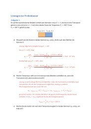
gives a resonant response at 21 MHz. Figure<br />
1A shows one such cylinder. The metamaterial<br />
is formed by stacking together many of<br />
these cylinders.<br />
In an early demonstration, it was shown that<br />
Swiss roll metamaterials could be applied in the<br />
MRI environment (2). A bundle of Swiss rolls<br />
was used to duct flux from an object to a remote<br />
detector. The metamaterial used in these experiments<br />
was lossy, and all the positional information<br />
in the image was provided by the spatial<br />
encoding system of the MRI machine. Nevertheless,<br />
it was clear from this work that such<br />
metamaterials could perform a potentially useful<br />
and unique function.<br />
Metamaterials and Resonant Response<br />
Why does a set of conductors shaped into Swiss<br />
rolls behave like a magnetic material In this<br />
structure, the coiled copper sheets have a selfcapacitance<br />
and self-inductance that create a<br />
resonance. The currents that flow when this<br />
resonance is activated couple strongly to an<br />
applied magnetic field, yielding an effective<br />
permeability that can reach quite high values.<br />
At the resonant frequency, a slab of Swiss roll<br />
composite behaves as a collection of magnetic<br />
wires: A magnetic field distribution incident on<br />
one face of the slab is transported uniformly to<br />
the other, in the same way that an electric field<br />
distribution would be transported by a bundle of<br />
electrically conducting wires. In real materials<br />
of course, there is loss, and this limits the<br />
resolution of the transfer to roughly d/Im(),<br />
where d is the thickness of the slab and Im()is<br />
the imaginary part of the permeability. This<br />
field transference was demonstrated (3) byarranging<br />
an antenna in the shape of the letter M<br />
as the source and mapping the transmitted magnetic<br />
field distribution (the fields near a current-<br />
788<br />
6 AUGUST 2004 VOL 305 SCIENCE www.sciencemag.org
carrying wire are predominantly magnetic). On<br />
resonance, the Swiss roll structure transmitted the<br />
incident field pattern across the slab (Fig. 1B), and<br />
the resolution matched that predicted by theory.<br />
The image transference was also demonstrated<br />
in an MRI machine (4). Here, the same<br />
M-shaped antenna was used both as the source<br />
of the RF excitation field and as the detector for<br />
the signal, and the metamaterial was tested<br />
twice over. First, it had to transmit the excitation<br />
field without degradation of spatial information<br />
so that the required spin pattern was<br />
excited in the sample. Second, the signal from<br />
that spin pattern had to be conveyed faithfully<br />
back to the receiver. This experiment demonstrated<br />
that a high-performance metamaterial<br />
could act as a magnetic face plate and convey<br />
information from one side to the other without<br />
loss of spatial information (Fig. 1C).<br />
Medical imaging is but one example of the<br />
potential utility of artificial magnetic materials.<br />
Although artificial magnetic metamaterials<br />
R EVIEW<br />
Fig. 1. (A) A single element of Swiss roll metamaterial. (B) An array of such<br />
elements is assembled into a slab and the RF magnetic field from an<br />
M-shaped antenna, placed below the slab, is reproduced on the upper<br />
surface. The red circles show the location of the rolls, which were 1 cm in<br />
diameter. (C) The resulting image taken in an MRI machine, showing that<br />
the field pattern is transmitted back and forth through the slab.<br />
have unique properties, at these lower frequencies<br />
magnetism is also exhibited by existing<br />
conventional materials. As we look to higher<br />
frequencies, on the other hand, conventional<br />
magnetism tails off and artificial magnetism<br />
may play an increasingly important role.<br />
A frequency range of particular interest occurs<br />
between 1 and 3 THz, a region that represents a<br />
natural breakpoint between magnetic and electric<br />
response in conventional materials. At lower frequencies,<br />
inherently magnetic materials (those<br />
whose magnetism results from unpaired electron<br />
spins) can be found that exhibit resonances. At<br />
higher frequencies, nearly all materials have electronic<br />
resonances that result from lattice vibrations<br />
or other mechanisms and give rise to electric<br />
response. The mid-THz region represents the<br />
point where electric response is dying out from the<br />
high-frequency end and magnetic response is dying<br />
out from the low-frequency end: Here, nature<br />
does not provide any strongly dielectric or magnetic<br />
materials.<br />
Metamaterials, on the other hand, can be<br />
constructed to provide this response. At higher<br />
frequencies, the split ring resonator (SRR),<br />
another conducting structure, can be conveniently<br />
used to achieve a magnetic response<br />
(1). The SRR consists of a planar set of<br />
concentric rings, each ring with a gap. Because<br />
the SRR is planar, it is easily fabricated<br />
by lithographic methods at scales appropriate<br />
for low frequencies to optical frequencies.<br />
Recently, an SRR composite designed to<br />
exhibit a magnetic resonance at THz frequencies<br />
was fabricated (5). The size of the SRRs<br />
was on the order of 30 m, 10 times smaller<br />
than the 300-m wavelength at 1 THz. Scattering<br />
experiments confirmed that the SRR<br />
medium had a magnetic resonance that could<br />
be tuned throughout the THz band by slight<br />
changes to the geometrical SRR parameters.<br />
Both the Swiss roll metamaterial and the<br />
THz SRR metamaterial illustrate the advantage<br />
of developing artificial magnetic response.<br />
But metamaterials can take us even<br />
further, to materials that have no analog in<br />
conventional materials.<br />
Negative Material Response<br />
A harmonic oscillator has a resonant frequency,<br />
at which a small driving force can produce<br />
a very large displacement. Think of a<br />
mass on a spring: Below the resonant frequency,<br />
the mass is displaced in the same<br />
direction as the applied force. However,<br />
above the resonant frequency, the mass is<br />
displaced in a direction opposite to the applied<br />
force. Because a material can be modeled<br />
as a set of harmonically bound charges,<br />
the negative resonance response translates<br />
directly to a negative material response, with<br />
the applied electric or magnetic field acting<br />
on the bound charges corresponding to the<br />
force and the responding dipole moment corresponding<br />
to the displacement. A resonance in<br />
the material response leads to negative values<br />
for ε or above the resonant frequency.<br />
Nearly all familiar materials, such as glass<br />
or water, have positive values for both ε and<br />
. It is less well recognized that materials are<br />
common for which ε is negative. Many<br />
metals—silver and gold, for example—<br />
have negative ε at wavelengths in the visible<br />
spectrum. A material having either (but<br />
not both) ε or negative is opaque to<br />
electromagnetic radiation.<br />
Light cannot get into a metal, or at least it<br />
cannot penetrate very far, but metals are not<br />
inert to light. It is possible for light to be<br />
trapped at the surface of a metal and propagate<br />
around in a state known as a surface<br />
plasmon. These surface states have intriguing<br />
properties which are just beginning to be<br />
exploited in applications (6).<br />
Whereas material response is fully characterized<br />
by the parameters ε and , the optical<br />
properties of a transparent material are often<br />
more conveniently described by a different parameter,<br />
the refractive index, n, given by n <br />
ε. A wave travels more slowly in a medium<br />
such as glass or water by a factor of n. All<br />
known transparent materials possess a positive<br />
index because ε and are both positive.<br />
Yet, the allowed range of material response<br />
does not preclude us from considering<br />
a medium for which both ε and are negative.<br />
More than 35 years ago Victor Veselago<br />
pondered the properties of just such a medium<br />
(7). Because the product ε is positive,<br />
taking the square root gives a real number for<br />
the index. We thus conclude that materials<br />
with negative ε and are transparent to light.<br />
There is a wealth of well-known phenomena<br />
associated with electromagnetic wave<br />
propagation in materials. All of these phenomena<br />
must be reexamined when ε and <br />
are simultaneously negative. For example,<br />
the Doppler shift is reversed, with a light<br />
source moving toward an observer being<br />
down-shifted in frequency. Likewise, the<br />
www.sciencemag.org SCIENCE VOL 305 6 AUGUST 2004 789
R EVIEW<br />
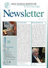
Fig. 2. Negative refraction in operation:<br />
On the left, a ray enters a negatively<br />
refracting medium and is bent the wrong<br />
way relative to the surface normal, forming<br />
a chevron at the interface. On the<br />
right, we sketch the wave vectors: Negative<br />
refraction requires that the wave vector<br />
and group velocity (the ray velocity)<br />
point in opposite directions.<br />
Cherenkov radiation from a charge passing<br />
through the material is emitted in the opposite<br />
direction to the charge’s motion rather than in<br />
the forward direction (7).<br />
The origin of this newly predicted behavior<br />
can be traced to the distinction between<br />
the group velocity, which characterizes the<br />
flow of energy, and the phase velocity, which<br />
characterizes the movement of the wave<br />
fronts. In conventional materials, the group<br />
and phase velocities are parallel. By contrast,<br />
the group and phase velocities point in opposite<br />
directions when ε 0 and 0 (Fig. 2).<br />
The reversal of phase and group velocity<br />
in a material implies a simply stated but<br />
profound consequence: The sign of the refractive<br />
index, n, must be taken as negative.<br />
After the early work of Veselago, interest<br />
in negative index materials evaporated, because<br />
no known naturally occurring material<br />
exhibits a frequency band with 0 and<br />
also possesses ε 0. The situation changed<br />
in 2000, however, when a composite structure<br />
based on SRRs was introduced and<br />
shown to have a frequency band over which ε<br />
and were both negative<br />
A<br />
(8). The negative occurred<br />
at frequencies above<br />
the resonant frequency of<br />
the SRR structure. The negative<br />
ε was introduced by<br />
interleaving the SRR lattice<br />
with a lattice of conducting<br />
wires. A lattice of wires<br />
possesses a cutoff frequency<br />
below which ε is negative<br />
(9); by choosing the parameters<br />
of the wire lattice<br />
such that the cutoff frequency<br />
was significantly above<br />
the SRR resonant frequency,<br />
the composite was made<br />
to have an overlapping region<br />
where both ε and <br />
were negative. This preliminary<br />
experiment showed that Veselago’s hypothesis<br />
could be realized in artificial structures<br />
and kicked off the rapidly growing field<br />
of negative index metamaterials.<br />
Negative Refraction and<br />
Subwavelength Resolution<br />
Experimentally, the refractive index of a<br />
material can be determined by measuring<br />
the deflection of a beam as it enters or<br />
leaves the interface to a material at an<br />
angle. The quantitative statement of refraction<br />
is embodied in Snell’s law, which relates<br />
the exit angle of a beam, 2 , as measured with<br />
respect to a line drawn perpendicular to the<br />
interface of the material, to the angle of<br />
incidence, 1 , by the formula<br />
sin( 1 ) nsin( 2 )<br />
The refractive index determines the<br />
amount by which the beam is deflected. If<br />
the index is positive, the exiting beam is<br />
deflected to the opposite side of the surface<br />
normal, whereas if the index is negative,<br />
the exiting beam is deflected the same side<br />
of the normal (Fig. 2).<br />
In 2001, a Snell’s law experiment was performed<br />
on a wedge-shaped metamaterial designed<br />
to have a negative index of refraction at<br />
microwave frequencies (10). In this experiment,<br />
a beam of microwaves was directed onto the<br />
flat portion of the wedge sample, passing<br />
through the sample undeflected, and then refracting<br />
at the second interface. The angular<br />
dependence of the refracted power was then<br />
measured around the circumference, establishing<br />
the angle of refraction.<br />
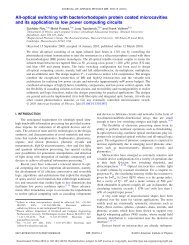
The result of the experiment (Fig. 3) indicated<br />
quite clearly that the wedge sample<br />
refracted the microwave beam in a manner<br />
consistent with Snell’s law. Figure 3B shows<br />
the detected power as a function of angle for<br />
a Teflon wedge (n 1.5, blue curve) compared<br />
to that of the NIM wedge (red curve).<br />
The location of the peak corresponding to the<br />
negative index material (NIM) wedge implies<br />
an index of –2.7.<br />
Although the experimental results appeared<br />
to confirm that the metamaterial<br />
sample possessed a negative refractive index,<br />
the theoretical foundation of negative<br />
refraction was challenged in 2002 (11). It<br />
was argued that the inherent frequencydispersive<br />
properties of negative index materials<br />
would prevent information-carrying<br />
signals from truly being negatively refracted.<br />
The theoretical issue was subsequently<br />
addressed by several authors (12–14), who<br />
concluded that, indeed, time-varying signals<br />
could also be negative refracted.<br />
Since this first demonstration of negative<br />
refraction, two more Snell’s law experiments<br />
have been reported, both using<br />
metamaterial wedge samples similar in design<br />
to that used in the first demonstration.<br />
These experiments have addressed aspects<br />
not probed in the first experiment. In one of<br />
the experiments, for example, spatial maps<br />
of the electromagnetic fields were made as<br />
a function of distance from the wedge to the<br />
detector. In addition, wedge samples were<br />
used with two different surface cuts to<br />
confirm that the angle of refraction was<br />
consistent with Snell’s law (15). In the<br />
second of these experiments, the negatively<br />
refracted beam was measured at much farther<br />
distances from the wedge sample (16).<br />
Moreover, in this latter experiment, the<br />
metamaterial sample was carefully designed<br />
such that material losses were minimized<br />
and the structure presented a better<br />
impedance match to free space; in this<br />
manner, much more energy was transmitted<br />
through the sample, making the negatively<br />
refracted beam easier to observe and much<br />
less likely to be the result of any experimental<br />
artifacts. These additional measurements<br />
have sufficed to convince most that<br />
materials with negative refractive index are<br />
indeed a reality.<br />
Fig. 3. (A) A negative index metamaterial formed by SRRs and wires deposited on opposite sides lithographically on<br />
standard circuit board. The height of the structure is 1 cm. (B) The power detected as a function of angle in a Snell’s law<br />
experiment performed on a Teflon sample (blue curve) and a negative index sample (red curve).<br />
B<br />
790<br />
6 AUGUST 2004 VOL 305 SCIENCE www.sciencemag.org
Having established the reality of negative<br />
refraction, we are now free to investigate other<br />
phenomena related to negative index materials.<br />
We quickly find that some of the most longheld<br />
notions related to waves and optics must<br />
be rethought! A key example is the case of<br />
imaging by a lens. It is an accepted convention<br />
that the resolution of an image is limited by the<br />
wavelength of light used. The wavelength limitation<br />
of optics imposes serious constraints on<br />
optical technology: Limits to the density with<br />
which DVDs can be written and the density<br />
of electronic circuitry created by lithography<br />
are manifestations of the wavelength limitation.<br />
Yet, there is no fundamental reason why<br />
an image should not be created with arbitrarily<br />
high resolution. The wavelength limitation<br />
is a result of the optical configuration of<br />
conventional imaging.<br />
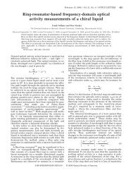
Negative refraction by a slab of material<br />
bends a ray of light back toward the axis<br />
and thus has a focusing effect at the point<br />
where the refracted rays meet the axis (Fig.<br />
4A). It was recently observed (17) that a<br />
negative index lens exhibits an entirely new<br />
type of focusing phenomenon, bringing together<br />
not just the propagating rays but also<br />
the finer details of the electromagnetic near<br />
fields that are evanescent and do not propagate<br />
(Fig. 4B). For a planar slab of negative<br />
index material under idealized conditions,<br />
an image plane exists that contains a<br />
perfect copy of an object placed on the opposite<br />
side of the slab. Although realizable materials<br />
will never meet the idealized conditions,<br />
nevertheless these new negative index concepts<br />
Fig. 4. Perfect lensing in action: A slab of<br />
negative material effectively removes an<br />
equal thickness of space for (A) the far<br />
field and (B) the near field, translating the<br />
object into a perfect image. (C) Microwave<br />
experiments by the Eleftheriades<br />
group (26) demonstrate that subwavelength<br />
focusing is possible, limited only<br />
by losses in the system. (D) Measured<br />
data are shown in red and compared to<br />
the perfect results shown in blue. Losses<br />
limit the resolution to less than perfect<br />
but better than the diffraction limit<br />
shown in green.<br />
show that subwavelength imaging is achievable,<br />
in principle; we need no longer dismiss<br />
this possibility from consideration.<br />
This trick of including the high-resolution<br />
but rapidly decaying part of the image is<br />
achieved by resonant amplification of the fields.<br />
Materials with either negative permittivity or<br />
negative permeability support a host of surface<br />
modes closely related to surface plasmons,<br />
commonly observed at metal surfaces (6), and<br />
it is these states that are resonantly excited. By<br />
amplifying the decaying fields of a source, the<br />
surface modes restore them to the correct amplitude<br />
in the image plane.<br />
The term lens is a misnomer when describing<br />
focusing by negative index materials. Recent<br />
work (18, 19) has shown that a more<br />
accurate description of a negative index material<br />
is negative space. To clarify, imagine a slab<br />
of material with thickness d for which<br />
ε –1 and –1<br />
Then, optically speaking, it is as if the slab<br />
had grabbed an equal thickness of empty<br />
space next to it and annihilated it. In effect,<br />
the new lens translates an optical object a<br />
distance 2d down the axis to form an image.<br />
The concept of the “perfect lens” at first met<br />
with considerable opposition (20, 21), but the<br />
difficulties raised have been answered by clarification<br />
of the concept and its limitations (22,<br />
23), by numerical simulation (24, 25), and in<br />
the past few months by experiments.<br />
In a recent experiment, a two-dimensional<br />
version of a negative index material has been<br />
assembled from discrete elements arranged on a<br />
R EVIEW<br />
planar circuit board (26). A detail of the experiment<br />
(Fig. 4C) shows the location of a point<br />
source and the expected location of the<br />
image. Figure 4D shows the experimental<br />
data, where the red curve is the measured<br />
result and lies well within the green curve,<br />
the calculated diffraction-limited result. A<br />
more perfect system with reduced losses<br />
would produce better focusing.<br />
The conditions for the “perfect lens” are<br />
rather severe and must be met rather accurately<br />
(23). This is a particular problem at<br />
optical frequencies where any magnetic activity<br />
is hard to find. However, there is a<br />
compromise that we can make if all the dimensions<br />
of the system are much less than<br />
the wavelength: As stated earlier, over short<br />
distances the electric and magnetic fields are<br />
independent. We may choose to concentrate<br />
entirely on the electric fields; in which case it<br />
is only necessary to tune to ε –1 and we<br />
can ignore completely. This “poor man’s”<br />
lens will focus the electrostatic fields, limited<br />
only by losses in the system. Thus, it has been<br />
proposed that a thin slab of silver a few<br />
nanometers thick can act as a lens (17). Experiments<br />
have shown amplification of light<br />
by such a system in accordance with theoretical<br />
predictions (27).<br />
Photonic Crystals and Negative<br />
Refraction<br />
Metamaterials based on conducting elements<br />
have been used to demonstrate negative refraction<br />
with great success. However, the use<br />
of conductors at higher frequencies, especially<br />
optical, can be problematic because of<br />
losses. As an alternative, many researchers<br />
have been investigating the potential of negative<br />
refraction in the periodic structures<br />
known as photonic crystals (28). These materials<br />
are typically composed of insulators<br />
and therefore can exhibit very low losses,<br />
even at optical frequencies.<br />
In photonic crystals, the size and periodicity<br />
of the scattering elements are on the<br />
order of the wavelength rather than being<br />
much smaller. Describing a photonic crystal<br />
as a homogeneous medium is inappropriate,<br />
so it is not possible to define values of ε or .<br />
Nevertheless, diffractive phenomena in photonic<br />
crystals can lead to the excitation of<br />
waves for which phase and group velocities<br />
are reversed in the same manner as in negative<br />
index metamaterials. Thus, under the<br />
right conditions, negative refraction can be<br />
observed in photonic crystals.<br />
In 2000, it was shown theoretically that<br />
several photonic crystal configurations could<br />
exhibit the same types of optical phenomena<br />
predicted for negative index materials, including<br />
negative refraction and imaging by a<br />
planar surface (23).<br />
Since then, several versions of photonic<br />
crystals have been used to demonstrate neg-<br />
www.sciencemag.org SCIENCE VOL 305 6 AUGUST 2004 791
R EVIEW<br />
ative refraction. For example, a metallic photonic<br />
crystal, formed into the shape of a<br />
wedge, was used in a Snell’s law experiment<br />
(29). In an alternative approach, the shift in<br />
the exit position of a beam incident at an<br />
angle to one face of a flat dielectric photonic<br />
crystal slab was used to confirm the effective<br />
negative refractive index (30). Although<br />
these experiments have been performed at<br />
microwave frequencies, the same negative<br />
refracting structures scaled to optical frequencies<br />
would possess far less loss than the<br />
metamaterials based on conducting elements.<br />
Photonic crystals have also been used to<br />
demonstrate focusing (31). Images as<br />
sharply defined as /5 can be obtained at<br />
microwave frequencies with the use of photonic<br />
crystal slab lenses (32). The work in<br />
photonic crystals is an example of where<br />
the identification of new material parameters<br />
has prompted the development of similar<br />
concepts in other systems.<br />
New Materials, New Physics<br />
We rely on the electromagnetic material parameters<br />
such as the index, or ε and , to<br />
replace the complex and irrelevant electromagnetic<br />
details of structures much smaller<br />
than the wavelength. This is why, for example,<br />
we can understand how a lens focuses<br />
light without concern about the motion of<br />
each of the atoms of which the lens is composed.<br />
With the complexity of the material<br />
removed from consideration, we are free to<br />
use the material properties to design applications<br />
or study other wave propagation phenomena<br />
with great flexibility.<br />
The past few years have illustrated the<br />
power of the metamaterials approach, because<br />
new material responses, some with no<br />
analog in conventional materials, are now<br />
available for exploration. The examples presented<br />
here, including artificial magnetism,<br />
negative refraction, and near-field focusing,<br />
are just the earliest of the new phenomena to<br />
emerge from the development of artificial<br />
materials. As we move forward, our ability to<br />
realize the exotic and often dramatic physics<br />
predicted for metamaterials will now depend<br />
on the quality of metamaterials.<br />
References and Notes<br />
1. J. B. Pendry, A. J. Holden, D. J. Robbins, W. J. Stewart,<br />
IEEE Trans. Microwave <strong>Theory</strong> Tech. 47, 2075 (1999).<br />
2. M. C. K. Wiltshire et al., Science 291, 849 (2001).<br />
3. M. C. K. Wiltshire, J. V. Hajnal, J. B. Pendry, D. J.<br />
Edwards, C. J. Stevens, Opt. Express 11, 709 (2003).<br />
4. M. C. K. Wiltshire et al., Proc. Int. Soc. Mag. Reson.<br />
Med. 11, 713 (2003).<br />
5. T. J. Yen et al., Science 303, 1494 (2004).<br />
6. W. L. Barnes, A. Dereux, T. W. Ebbesen, Nature 424,<br />
824 (2003).<br />
7. V. G. Veselago, Sov. Phys. Usp. 10, 509 (1968).<br />
8. D. R. Smith, W. J. Padilla, D. C. Vier, S. C. Nemat-<br />
Nasser, S. Schultz, Phys. Rev. Lett. 84, 4184 (2000).<br />
9. J. B. Pendry, A. J. Holden, W. J. Stewart, I. Youngs,<br />
Phys. Rev. Lett. 76, 4773 (1996).<br />
10. R. Shelby, D. R. Smith, S. Schultz, Science 292, 77 (2001).<br />
11. P. M. Valanju, R. M. Walser, A. P. Valanju, Phys. Rev.<br />
Lett. 88, 187401 (2002).<br />
12. D. R. Smith, D. Schurig, J. B. Pendry, Appl. Phys. Lett.<br />
81, 2713 (2002).<br />
13. J. Pacheco, T. M. Grzegorczyk, B.-I. Wu, Y. Zhang, J. A.<br />
Kong, Phys. Rev. Lett. 89, 257401 (2002).<br />
14. J. B. Pendry, D. R. Smith, Phys. Rev. Lett. 90, 029703 (2003).<br />
15. A. A. Houck, J. B. Brock, I. L. Chuang, Phys. Rev. Lett.<br />
90, 137401 (2003).<br />
16. C. G. Parazzoli, R. B. Greegor, K. Li, B. E. C. Koltenbah,<br />
M. Tanielian, Phys. Rev. Lett. 90, 107401 (2003).<br />
17. J. B. Pendry, Phys. Rev. Lett. 85, 3966 (2000).<br />
18. J. B. Pendry, S. A. Ramakrishna, J. Phys. Cond. <strong>Matter</strong><br />
15, 6345 (2003).<br />
19. A. Lakhtakia, Int. J. Infrared Millimeter Waves 23, 339<br />
(2002).<br />
20. N. Garcia, M. Nieto-Vesperinas, Phys. Rev. Lett. 88,<br />
207403 (2002).<br />
21. G. W. ‘t Hooft, Phys. Rev. Lett. 87, 249701 (2001).<br />
22. J. T. Shen, P. M. Platzman, Appl. Phys. Lett. 80, 3286<br />
(2002).<br />
23. D. R. Smith et al., Appl. Phys. Lett. 82, 1506 (2003).<br />
24. P. Kolinko, D. R. Smith, Opt. Express 11, 640<br />
(2003).<br />
25. S. A. Cummer, Appl. Phys. Lett. 82, 1503 (2003).<br />
26. A. Grbic, G. V. Eleftheriades, Phys. Rev. Lett. 92,<br />
117403 (2004).<br />
27. Z. W. Liu, N. Fang, T. J. Yen, X. Zhang, Appl. Phys. Lett.<br />
83, 5184 (2003).<br />
28. M. Notomi, Phys. Rev. B 62, 10696 (2000).<br />
29. P. V. Parimi et al., Phys. Rev. Lett. 92, 127401<br />
(2004).<br />
30. E. Cubukcu, K. Aydin, E. Ozbay, S. Foteinopoulou,<br />
C. M. Soukoulis, Nature 423, 604 (2003).<br />
31. P. V. Parimi, W. T. Lu, P. Vodo, S. Sridhar, Nature 426,<br />
404 (2003).<br />
32. E. Cubukcu, K. Aydin, E. Ozbay, S. Foteinopolou, C. M.<br />
Soukoulis, Phys. Rev. Lett. 91, 207401 (2003).<br />
33. J.B.P. thanks the European Commission (EC) under<br />
project FP6-NMP4-CT-2003-505699 for financial<br />
support. D.R.S. also acknowledges support from Defense<br />
Advanced Research Projects Agency (DARPA)<br />
(DAAD19-00-1-0525), and D.R.S. and J.B.P. received<br />
support from DARPA/Office of Naval Research Multidisciplinary<br />
Research Program of the University Research<br />
Initiative grant N00014-01-1-0803. Additionally<br />
J.B.P. acknowledges support from the Engineering<br />
and Physical Sciences Research Council, and<br />
M.C.K.W., from the EC Information Societies Technology<br />
(IST) program Development and Analysis of Left-<br />
Handed Materials (DALHM), project number IST-<br />
2001-35511.<br />
792<br />
6 AUGUST 2004 VOL 305 SCIENCE www.sciencemag.org