MSD SCI Series
MSD SCI Series
MSD SCI Series

You also want an ePaper? Increase the reach of your titles
YUMPU automatically turns print PDFs into web optimized ePapers that Google loves.
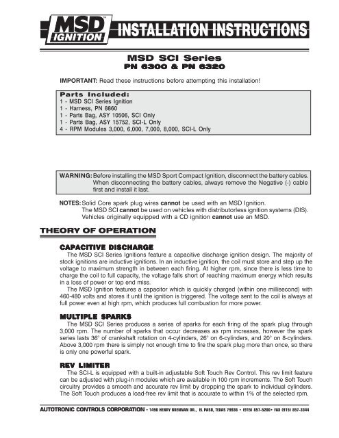
<strong>MSD</strong> <strong>SCI</strong> <strong>Series</strong><br />
PN 6300 & PN 6320<br />
IMPORTANT: Read these instructions before attempting this installation!<br />
Parts Included:<br />
1 - <strong>MSD</strong> <strong>SCI</strong> <strong>Series</strong> Ignition<br />
1 - Harness, PN 8860<br />
1 - Parts Bag, ASY 10506, <strong>SCI</strong> Only<br />
1 - Parts Bag, ASY 15752, <strong>SCI</strong>-L Only<br />
4 - RPM Modules 3,000, 6,000, 7,000, 8,000, <strong>SCI</strong>-L Only<br />
WARNING:Before installing the <strong>MSD</strong> Sport Compact Ignition, disconnect the battery cables.<br />
When disconnecting the battery cables, always remove the Negative (-) cable<br />
first and install it last.<br />
NOTES: Solid Core spark plug wires cannot be used with an <strong>MSD</strong> Ignition.<br />
The <strong>MSD</strong> <strong>SCI</strong> cannot be used on vehicles with distributorless ignition systems (DIS).<br />
Vehicles originally equipped with a CD ignition cannot use an <strong>MSD</strong>.<br />
THEORY OF OPERATION<br />
CAPACITIVE DISCHARGE<br />
The <strong>MSD</strong> <strong>SCI</strong> <strong>Series</strong> Ignitions feature a capacitive discharge ignition design. The majority of<br />
stock ignitions are inductive ignitions. In an inductive ignition, the coil must store and step up the<br />
voltage to maximum strength in between each firing. At higher rpm, since there is less time to<br />
charge the coil to full capacity, the voltage falls short of reaching maximum energy which results<br />
in a loss of power or top end miss.<br />
The <strong>MSD</strong> Ignition features a capacitor which is quickly charged (within one millisecond) with<br />
460-480 volts and stores it until the ignition is triggered. The voltage sent to the coil is always at<br />
full power even at high rpm, which produces full combustion for more power.<br />
MULTIPLE SPARKS<br />
The <strong>MSD</strong> <strong>SCI</strong> <strong>Series</strong> produces a series of sparks for each firing of the spark plug through<br />
3,000 rpm. The number of sparks that occur decreases as rpm increases, however the spark<br />
series lasts 36° of crankshaft rotation on 4-cylinders, 26° on 6-cylinders, and 20° on 8-cylinders.<br />
Above 3,000 rpm there is simply not enough time to fire the spark plug more than once, so there<br />
is only one powerful spark.<br />
REV LIMITER<br />
The <strong>SCI</strong>-L is equipped with a built-in adjustable Soft Touch Rev Control. This rev limit feature<br />
can be adjusted with plug-in modules which are available in 100 rpm increments. The Soft Touch<br />
circuitry provides a smooth and accurate rev limit by dropping the spark to individual cylinders.<br />
The Soft Touch produces a load-free rev limit that is accurate to within 1% of the selected rpm.<br />
AUTOTRONIC CONTROLS CORPORATION • 1490 HENRY BRENNAN DR., EL PASO, TEXAS 79936 • (915) 857-5200• FAX (915) 857-3344
2 INSTALLATION INSTRUCTIONS<br />
GENERAL INFORMATION<br />
BATTERY<br />
TERY<br />
An <strong>MSD</strong> <strong>SCI</strong> <strong>Series</strong> Ignition will operate on any negative ground, 12 volt electrical system with a<br />
distributor. The <strong>MSD</strong> can be used with a 16 volt battery and can withstand a momentary 24 volts<br />
in case of a jump start. The ignition will deliver full voltage with a supply of 9 - 18 volts and will<br />
operate with a supply voltage as low as 5 volts.<br />
If your application does not use an alternator, allow at least 15 amp/hour for every half hour of<br />
operation. If the engine is cranked with the same battery or other accessories such as an electric<br />
fuel pump, fan or water pump are used, the amp/hour rating must be increased.<br />
COILS<br />
The <strong>MSD</strong> Sport Compact Ignition can be used with most stock coils and aftermarket coils that<br />
are designed to replace the stock coils. There are some “race only” coils such as the <strong>MSD</strong> Pro<br />
Power Coil, PN 8201, that cannot be used with the <strong>SCI</strong> <strong>Series</strong> Ignition. For more information on<br />
recommended coils, consult the supplied Coil Application Chart or check with the manufacturer<br />
of the coil. If you have any questions concerning coils, contact our <strong>MSD</strong> Customer Service<br />
Department at (915) 855-7123.<br />
TACHOMETERS/FUEL INJECTION<br />
The <strong>MSD</strong> <strong>SCI</strong> <strong>Series</strong> Ignitions feature a Tach Output Terminal on the side of the unit. This terminal<br />
provides a trigger signal for tachometers, fuel injection, a shift light or other add-on devices that<br />
require a 12 volt square wave rpm signal with a 20% duty cycle. Some vehicles with factory<br />
tachometers may require a Tach Adapter to operate with the <strong>MSD</strong>. For more information on<br />
tachometers and <strong>MSD</strong> Tach Adapters, refer to the Tachometer Section on page 6.<br />
SPARK PLUGS AND WIRES<br />
Spark plug wires are very important to the operation of the <strong>SCI</strong> <strong>Series</strong> Ignition. A good quality,<br />
helically wound wire and proper routing are required to obtain the best performance from the<br />
<strong>SCI</strong> ignition. <strong>MSD</strong> recommends using a helically wound suppression type wire such as the <strong>MSD</strong><br />
8mm Heli-Core or 8.5mm Super Conductor Spark Plug Wire. This type of wire provides a good<br />
path for the spark to follow while keeping Electro Magnetic Interference (EMI) to a minimum.<br />
Excessive EMI, such as the amount that is produced by solid core spark plug wires, will interfere<br />
with the operation of the <strong>MSD</strong>.<br />
Note: Solid Core spark plug wires cannot be used with any <strong>MSD</strong> Ignition products.<br />
Routing: Correct routing of the plug wires is also important to performance. Wires should<br />
be routed away from sharp edges and engine heat sources. If there are two wires that are<br />
next to each other, the wires should be routed away from each other to avoid inducing a<br />
spark into the other wire. To add more heat protection to the wires, <strong>MSD</strong> offers Pro Heat Guard,<br />
PN 3411. This is a glass woven and silicone coated protective sleeve that can be slid over the<br />
plug wires. For extra protection of the spark plug boots, <strong>MSD</strong> also offers Pro-Heat Boot Guard,<br />
PN 3412.<br />
Spark Plugs: Choosing the correct spark plug design and heat range is important when trying<br />
to get the best performance possible. Since there are so many engine combinations and<br />
manufacturers, <strong>MSD</strong> does not recommend which plug or gap is exactly right for your application.<br />
<strong>MSD</strong> suggests that you follow the engine builder or manufacturer’s specification for spark plugs.<br />
With that, you can then experiment with the plug gap to obtain the best performance. The gap of<br />
the plugs can be opened in 0.005” increments, then tested until the best performance is obtained.<br />
These examples are just starting points to get you headed in the right direction. Every application<br />
is different and should be tested and tuned.<br />
AUTOTRONIC CONTROLS CORPORATION • 12120 1490 HENRY ESTHER LAMA, BRENNAN SUITE DR., 114, EL EL PASO, TEXAS 79936 ••(915) 857-5200 • FAX (915) 857-3344
INSTALLATION INSTRUCTIONS 3<br />
Sealing: Do not attempt to seal the <strong>MSD</strong>. All circuits of an <strong>MSD</strong> receive a thick conformal<br />
coating of Humi-Seal. This sealant protects the electronics from moisture. If you were to seal the<br />
unit, any moisture or water that may seep in through the wiring grommets will not be able to<br />
drain and may result in corrosion.<br />
Welding: If you plan on welding on your vehicle, to avoid possible damage to the ignition,<br />
always disconnect both the <strong>MSD</strong> Heavy Power cables from the battery. It is also recommended<br />
that the tach ground wire be disconnected.<br />
Distributor Cap and Rotor: It is recommended to install a new distributor cap and rotor when<br />
installing the Sport Compact Ignition. The cap should be clean inside and out especially the<br />
terminals and the rotor tip. On vehicles which use a small diameter cap, it is possible for the air<br />
inside the cap to become electrically charged causing crossfire which may result in misfire. This<br />
can be prevented by drilling a couple of vent holes in the cap. The holes should be placed<br />
between the terminals, at rotor height and away from any metal surfaces. If your environment<br />
demands it, place a small piece of screen over the hole to act as a filter.<br />
Initial Spark: It is normal, yet not very common, for the <strong>MSD</strong> to produce a spark when the<br />
ignition key is turned On. This is due to the capacitor being charged and the distributor pickup<br />
being in the correct position to trigger the ignition to fire. This could also occur when installing the<br />
positive battery cable.<br />
CYLINDER SELECT<br />
The Soft Touch Rev Limiter that is built into<br />
the <strong>MSD</strong> <strong>SCI</strong>-L is programmed for operation<br />
on an 8-cylinder engine. If you are installing<br />
one of these units on a 4 or 6-cylinder evenfire<br />
engine, the ignition must be modified.<br />
This is easily achieved through the cylinder<br />
select device on the side of the ignition. To<br />
program the ignition:<br />
1. Locate and remove the round black cover<br />
with a single Phillips screw.<br />
2. There are two wire loops, a Red and Blue<br />
loop. Refer to the chart in Figure 1 to<br />
determine which loop to cut for your<br />
application.<br />
3. After cutting the loop(s), turn the wire ends<br />
away from each other so they cannot come<br />
into contact. Install the cover and the screw.<br />
Figure 1 Cylinder Select Loops.<br />
MOUNTING<br />
The <strong>MSD</strong> Ignition may be mounted in any location except on the engine or near the exhaust<br />
manifold. Excessive heat at these locations may cause damage to the ignition. It can be mounted<br />
in most positions, except directly upside down (if upside down, moisture or water cannot escape).<br />
It is not recommended to mount the unit in an enclosed area such as the glovebox. When<br />
selecting a mounting location, make sure the cable harness will reach the battery and coil/<br />
distributor assembly. When a suitable location is found, hold the ignition in place and mark the<br />
location of the mounting holes. Using a 1/8” drill bit, drill a hole in each of the locations marked.<br />
Use the supplied self tapping screws to mount the ignition unit.<br />
AUTOTRONIC CONTROLS CORPORATION • 12120 1490 HENRY ESTHER BRENNAN LAMA, SUITE DR., 114, EL EL PASO, TEXAS 79936 • •(915) 857-5200 •• FAX FAX (915) 857-3344
4 INSTALLATION INSTRUCTIONS<br />
WIRING<br />
GENERAL WIRING INFORMATION<br />
Wire Length: All of the wires of the <strong>MSD</strong> Ignition may be shortened as long as quality connectors<br />
are used and crimped or soldered in place. To lengthen the wires, use one size bigger gauge<br />
wire (10 gauge for the power leads and 16 gauge for all other wires) with proper connections. All<br />
connections must be soldered and sealed.<br />
Grounds: A poor ground connection can cause many frustrating problems. When a wire is<br />
specified to go to ground, it should be connected to the battery negative terminal, engine block<br />
or chassis. The body is not a recomended ground. There should always be a ground strap<br />
between the engine and the chassis. Always securely connect the ground wire to a clean, paint<br />
free metal surface.<br />
Ballast Resistor: If your vehicle has a ballast resistor in line with the coil wiring, it is not necessary<br />
to bypass or remove it. This is because the <strong>MSD</strong> receives its main power directly from the<br />
battery.<br />
Routing Wires: The <strong>MSD</strong> wires should be routed away from direct heat such as the exhaust<br />
manifolds/headers and any sharp edges. The trigger wires should be routed separate from the<br />
other wires and spark plug wires. It is best if they are routed along a ground plane such as the<br />
block or firewall which creates an electrical shield. The magnetic pickup wires should always be<br />
routed separately and should be twisted together to help reduce extraneous interference.<br />
WIRE FUNCTIONS<br />
Power Leads<br />
Heavy Red<br />
Heavy Black<br />
These are the two heavy gauge wires (12 gauge) and are responsible for getting direct battery<br />
voltage to the ignition. The ignition has an internal fuse so no fuse is necessary.<br />
This wire connects directly to the battery positive (+) terminal or to a positive battery junction or the<br />
positive side of the starter solenoid. Note: Do not connect to the alternator.<br />
This wire connects to a good ground, either at the battery negative (-) terminal or to the engine.<br />
Red<br />
Connects to a switched 12 volt source. Such as the ignition key or switch.<br />
Orange Connects to the positive (+) terminal of the coil.<br />
Note: This is the only wire that makes electrical contact with the coil positive (+) terminal.<br />
Black<br />
Connects to the negative (-) terminal of the coil.<br />
Note: This is the only wire that makes electrical contact with the coil negative (-) terminal.<br />
Trigger Wires There are two circuits that can be used to trigger the <strong>MSD</strong> Ignition; a points circuit (White wire) and<br />
a Magnetic Pickup circuit (Violet and Green wires). The two circuits will never be used together.<br />
White<br />
This wire is used to connect to the points, electronic ignition amplifier output or to the Yellow wire of<br />
an <strong>MSD</strong> Timing Accessory. When this wire is used, the Magnetic Pickup connector is not used.<br />
Violet & Green These wires are routed together in one harness to form the Magnetic Pickup connector. The<br />
connector plugs directly into an <strong>MSD</strong> Distributor or Crank Trigger. It will also connect to factory<br />
magnetic pickups or other aftermarket pickups. The Violet wire is positive (+) and the Green is<br />
negative (-). When these wires are used, the White wire is not used. Note: Most EFI applications will<br />
use the White wire to trigger the <strong>MSD</strong>.<br />
AUTOTRONIC CONTROLS CORPORATION • 12120 1490 HENRY ESTHER LAMA, BRENNAN SUITE DR., 114, EL EL PASO, TEXAS 79936 ••(915) 857-5200 • FAX (915) 857-3344
INSTALLATION INSTRUCTIONS 5<br />
Figure 2 shows the polarity of other common<br />
magnetic pickups. If using a different<br />
magnetic pickup, use the <strong>MSD</strong> 2-Pin<br />
connector, PN 8824, for a direct plug-in<br />
installation.<br />
Common Mag Pickup Wires<br />
Distributor<br />
Colors<br />
Mag+ Mag-<br />
<strong>MSD</strong> Org/Blk Vio/Blk<br />
<strong>MSD</strong> Crank Trigger Violet Green<br />
Ford Orange Purple<br />
Accel 46/48000 <strong>Series</strong> Org/Blk Vio/Blk<br />
Accel 51/61000 <strong>Series</strong> Red Black<br />
Chrysler Org/Wht Black<br />
Mallory Org/Blk Vio/Blk<br />
Figure 2 Common Magnetic Pickups.<br />
WARNING: The <strong>MSD</strong> <strong>SCI</strong> <strong>Series</strong> Ignitions are capacitive discharge ignitions. High voltage is<br />
present at the coil primary terminals. Do not touch the coil or connect test equipment<br />
to the terminals.<br />
PRESTART CHECK LIST<br />
• The only wires connected to the coil terminals are the <strong>MSD</strong> Orange to coil positive and Black<br />
to coil negative.<br />
The small Red wire of the <strong>MSD</strong> is connected to a switched 12 volt source.<br />
If using a <strong>MSD</strong> <strong>SCI</strong>-L on a 4 or 6-cylinder engine the cylinder select must be modified.<br />
The <strong>MSD</strong> power leads are connected directly to the battery positive and negative terminals.<br />
The battery is connected and fully charged if not using an alternator.<br />
• The engine is equipped with at least one ground strap to the chassis.<br />
THEFT DETERRENT<br />
The <strong>MSD</strong> provides the opportunity to easily install a theft deterrent kill switch, Figure 3.<br />
White Wire Trigger: When using the White wire to trigger the <strong>MSD</strong>, install a single pole single<br />
throw switch (PN 8806) across the magnetic pickup Violet wire to ground. When the Violet wire<br />
is grounded, the vehicle will crank but not start.<br />
Magnetic Pickup Trigger: When using the mag pickup to trigger the <strong>MSD</strong>, install a single pole<br />
single throw switch (PN 8806) to the White wire and the other side to ground. When the White<br />
wire is grounded, the vehicle will crank but will not start.<br />
Figure 3 Connecting a Theft Deterrent Switch.<br />
AUTOTRONIC CONTROLS CORPORATION • 12120 1490 ESTHER HENRY LAMA, BRENNAN SUITE DR., 114, EL EL PASO, TEXAS 79936 ••(915) 857-5200 • FAX (915) 857-3344
6 INSTALLATION INSTRUCTIONS<br />
TROUBLESHOOTING<br />
Every Sport Compact Ignition undergoes numerous quality control checks including<br />
a four hour burn-in test. If you experience a problem with your <strong>MSD</strong>, our research has<br />
shown that the majority of problems are due to improper installation or poor<br />
connections. The Troubleshooting section has several checks and tests you can<br />
perform to ensure proper installation and operation of the <strong>MSD</strong>. If you have any<br />
questions concerning your <strong>MSD</strong>, call our Customer Service Department at (915) 855-<br />
7123, Monday - Friday, 8am to 5pm mountain time.<br />
TACH/FUEL ADAPTERS<br />
APTERS<br />
If your tachometer does not operate correctly or if you experience a no-run situation<br />
with your vehicle you probably need an <strong>MSD</strong> Tach/Fuel Adapter.<br />
Tachometers: The chart below lists the most common tachometers and if an Adapter<br />
is necessary. Before getting an Adapter, try connecting your tachometer trigger wire<br />
to the tach output terminal on the side of the <strong>MSD</strong>. This output produces a 12 volt<br />
square wave with a 20% duty cycle. If the tach still does not operate correctly, you will<br />
need a Tach Adapter. There are two Tach Adapters.<br />
PN 8920: If you are using the Magnetic Pickup connector (Green and Violet wires) to<br />
trigger the <strong>MSD</strong>, you will need the PN 8920.<br />
PN 8910: If you are using the White wire to trigger the <strong>MSD</strong> and your tachometer was<br />
triggered from the coil negative terminal (voltage triggered) you will need the PN<br />
8910.<br />
Fuel Injection: Some foreign vehicles with fuel injection systems may require an <strong>MSD</strong><br />
Tach/Fuel Injection Adapter to run properly. This is because many of these systems use the<br />
same trigger source to operate the <strong>MSD</strong>, the tachometer and the fuel injection. This results<br />
in a voltage signal that is too low to accurately trigger the fuel injection. To fix this, an <strong>MSD</strong><br />
Tach Adapter, PN 8910, will usually remedy the problem on the majority of vehicles. If the<br />
PN 8910 does not fix the problem, the PN 8910-EIS will be required.<br />
Note: Toyotas and Ford Probes will require the PN 8910-EIS Adapter.<br />
Tachometer Compatibility List<br />
AFTERMARKET TACHOMETER WHITE WIRE TRIGGER MAGNETIC TRIGGER CONNECTOR<br />
AUTOGAGE 8910 8920<br />
AUTOMETER NONE NONE<br />
FORD MOTORSPORTS NONE NONE<br />
MALLORY NONE NONE<br />
MOROSO NONE NONE<br />
STEWART 8910 8920<br />
S.W. & BI TORX NONE NONE<br />
SUN 8910 8920<br />
VDO 8910 8920<br />
CHRYSLER 8910 8920<br />
IMPORTS 8910 8920<br />
Note: On the list above, the trigger wire on tachometers that are marked NONE may be connected to the<br />
Tach Output Terminal on the <strong>MSD</strong> 6 <strong>Series</strong> Ignition Unit using the supplied Female Faston Receptacle.<br />
AUTOTRONIC CONTROLS CORPORATION • 12120 1490 HENRY ESTHER LAMA, BRENNAN SUITE DR., 114, EL EL PASO, TEXAS 79936 ••(915) 857-5200 • FAX (915) 857-3344
INSTALLATION INSTRUCTIONS 7<br />
MISSES AND INTERMITTENT PROBLEMS<br />
Generally, a miss or hesitation at higher rpm is usually not caused by the ignition. Most probable<br />
causes include a coil or plug wire failure, arcing from the cap or plug boot to ground or spark<br />
ionization inside the cap. Several areas to inspect are:<br />
• Always inspect the plug wires at the cap and at the plug for a tight connection and visually<br />
inspect for cuts, abrasions or burns.<br />
•<br />
Inspect the positive (+) and negative (-) coil terminal connections. Because the <strong>MSD</strong> is a<br />
Capacitive Discharge ignition and it receives a direct 12 volt source directly from the battery,<br />
there will not be any voltage at the coil positive (+) terminal even with the key turned On.<br />
During cranking or while the engine is running, very high voltage will be present at the coil. Do<br />
not connect any test equipment to the coil positive (+) or negative (-) terminals.<br />
WARNING: Do not touch the coil terminals during cranking or while the engine is running.<br />
• Make sure that the battery is fully charged and the connections are clean and tight. If you are<br />
not running an alternator this is an essential check. If the battery voltage falls below 10 volts<br />
during operation, the <strong>MSD</strong> output voltage will drop.<br />
Is the engine running lean Inspect the spark plugs and complete fuel system.<br />
•<br />
Inspect all wiring connections for corrosion or damage. Remember to always use proper<br />
connections followed by soldering and seal the connections completely.<br />
If everything checks out, use the following procedure to test the ignition for spark. <strong>MSD</strong> also<br />
offers an Ignition Tester, PN 8995, which can be used to check the entire ignition system,<br />
tachometers, rpm activated switches and shift lights without removing them from the vehicle.<br />
CHECKING FOR SPARK<br />
If triggering the ignition with the White wire:<br />
1. Make sure the ignition switch is in the “Off” position.<br />
2. Remove the coil wire from the distributor cap and set the terminal approximately 1/2" from<br />
ground.<br />
3. Disconnect the <strong>MSD</strong> White wire from the distributors points or ignition amplifier.<br />
4. Turn the ignition to the On position. Do not crank the engine.<br />
5. Tap the White wire to ground several times. Each time you pull the wire from ground, a spark<br />
should jump from the coil wire to ground. If spark is present, the ignition is working properly.<br />
If there is no spark skip to step 6 below.<br />
If triggering the ignition with the Magnetic Pickup connector:<br />
1. Make sure the ignition switch is in the “Off” position.<br />
2. Remove the coil wire from the distributor cap and set the terminal approximately 1/2" from<br />
ground.<br />
3. Disconnect the <strong>MSD</strong> magnetic pickup wires from the distributor.<br />
4. Turn the ignition to the On position. Do not crank the engine.<br />
5. With a small jumper wire, short the <strong>MSD</strong> Green and Violet magnetic pickup wires together.<br />
Each time you break this short, a spark should jump from the coil wire to ground. If spark is<br />
present, the ignition is working properly. If there is no spark skip to step 6 below.<br />
6. If there is no spark:<br />
A. Inspect all of the wiring.<br />
B. Substitute another coil and repeat the test. If there is now spark, the coil is at fault.<br />
C. If there is still no spark, check to make sure there is 12 volts on the small Red wire from the<br />
<strong>MSD</strong> when the key is in the On position. If 12 volts is not present, find another switched 12<br />
volt source and repeat the test.<br />
D. If, after following the test procedures and inspecting all of the wiring, there is still no spark,<br />
the <strong>MSD</strong> Ignition is in need of repair. See the Warranty and Service section for information.<br />
AUTOTRONIC CONTROLS CORPORATION • 12120 1490 ESTHER HENRY LAMA, BRENNAN SUITE DR., 114, EL EL PASO, TEXAS 79936 ••(915) 857-5200 • FAX (915) 857-3344
8 INSTALLATION INSTRUCTIONS<br />
WIRING DIAGRAMS<br />
The following wiring diagrams illustrate numerous installations on different vehicles and<br />
applications. If you experience difficulties when installing your <strong>MSD</strong> Sport Compact Ignition,<br />
contact our Customer Service Department at (915) 855-7123 Monday - Friday, 8am - 5pm<br />
mountain time or e-mail us at: msdtech@msdignition.com<br />
<strong>MSD</strong> SYSTEMS<br />
Installing to Points/Amplifier Style Ignitions<br />
NOTE: On dual point setups, it is recommended<br />
to remove the trailing set of points.<br />
<strong>MSD</strong> SYSTEMS<br />
Installing to a Magnetic Pickup Distributor<br />
NOTE: The PN 8460 distributor has been discontinued.<br />
AUTOTRONIC CONTROLS CORPORATION • 12120 1490 HENRY ESTHER LAMA, BRENNAN SUITE DR., 114, EL EL PASO, TEXAS 79936 ••(915) 857-5200 • FAX (915) 857-3344
INSTALLATION INSTRUCTIONS 9<br />
ACURA IGNITIONS<br />
Wiring a Honda/Acura w/Internal Coil<br />
Follow this procedure to install the <strong>MSD</strong> <strong>SCI</strong> <strong>Series</strong> Ignition to applications which will retain the<br />
use of the internal mounted coil. The distributor cap, rotor and dust cover must be removed<br />
during the wiring process. All wires must be routed to the locations described below, then cut<br />
to length and connected using the supplied solderless connectors.<br />
1. Disconnect the Black/Yellow wire with ring lug terminal from the positive side of the coil.<br />
Cover the ring lug terminal with electrical tape to prevent shorting.<br />
2. Disconnect the White/Blue jumper wire from the negative side of the coil.<br />
3. Connect the <strong>MSD</strong>’s Red wire to a switched 12 volt source, or splice it into the Black/Yellow<br />
wire leading into the distributor (original Coil + Wire).<br />
4. Connect the <strong>MSD</strong>’s Orange wire to the positive (+) side of the coil. No other wires should be<br />
connected to the positive side of the coil.<br />
5. Connect the <strong>MSD</strong>’s Black wire to the negative (-) side of the coil. No other wires should be<br />
connected to the negative side of the coil.<br />
6. Connect the <strong>MSD</strong>’s White wire to the White/Blue wire that used to be connected to coil (-).<br />
AUTOTRONIC CONTROLS CORPORATION • 12120 1490 ESTHER HENRY LAMA, BRENNAN SUITE DR., 114, EL EL PASO, TEXAS 79936 ••(915) 857-5200 • FAX (915) 857-3344
10 INSTALLATION INSTRUCTIONS<br />
ACURA IGNITIONS Wiring a Honda/Acura w/External Coil<br />
Modified Distributor Cap<br />
On nitrous, turbocharged or supercharged<br />
engines, it is recommended that<br />
an external coil such as an<br />
<strong>MSD</strong> Blaster be used. In<br />
order to use an external<br />
coil, a modified <strong>MSD</strong><br />
distributor cap will be<br />
required for this installation.<br />
If you would like to modify<br />
your factory distributor cap<br />
to accept an external coil,<br />
detailed instructions for this<br />
type of modification are shown<br />
on page 11.<br />
Honda Civic CRX 1.5L/1.6L 88-91<br />
Acura Integra 1.6L/1.8L 88-91<br />
Honda Civic 1.5L 1.6L w/VTEC & Hitachi Dist. 95-97<br />
Accord 2.2L w/Hitachi Dist. 93-97<br />
Honda Civic 1.5L 1.6L 92-97, Civic Del Sol 1.6L 93-97<br />
Acure Integra 1.8L 92-97<br />
Acura Integra 1.7L w/VTEC 94-97<br />
BLACK<br />
PN 8290<br />
PN 8291<br />
PN 8292<br />
PN 8293<br />
RED<br />
PN 82901<br />
N/A<br />
PN 82921<br />
N/A<br />
Follow this procedure to install the <strong>MSD</strong> <strong>SCI</strong> <strong>Series</strong> Ignition to applications which will be using<br />
the modified distributor cap with external coil. The <strong>MSD</strong> Ignition and Blaster Coil must be mounted<br />
before proceeding. The distributor cap, rotor and dust cover must be removed during the wiring<br />
process. All wires must be routed to the locations described below, then cut to length and<br />
connected using the supplied solderless connectors.<br />
1. Disconnect the Black/Yellow wire with ring lug terminal from the positive side of coil. Cover<br />
the ring lug terminal with electrical tape to prevent shorting.<br />
2. Disconnect the White/Blue jumper wire from the negative side of the coil and ignitor module.<br />
Remove the coil from the distributor housing.<br />
3. Connect the <strong>MSD</strong>’s Red wire to a switched 12 volt source, or splice it into the Black/Yellow<br />
wire leading into the distributor.<br />
4. Connect the <strong>MSD</strong>’s Orange wire to the positive (+) side of the coil. No other wires should be<br />
connected to the positive side of the coil.<br />
5. Connect the <strong>MSD</strong>’s Black wire to the negative (-) side of the coil. No other wires should be<br />
connected to the negative side of the coil.<br />
6. Connect the <strong>MSD</strong>’s White wire to terminal “C” on the igniter or to the White/Blue wire.<br />
AUTOTRONIC CONTROLS CORPORATION • 12120 1490 HENRY ESTHER LAMA, BRENNAN SUITE DR., 114, EL EL PASO, TEXAS 79936 ••(915) 857-5200 • FAX (915) 857-3344
INSTALLATION INSTRUCTIONS 11<br />
HONDA IGNITIONS<br />
Modifying the Factory Honda/Acura Distributor Cap<br />
On modified engines it is recommended that an<br />
external coil such as the <strong>MSD</strong> Blaster be used. To use<br />
an external coil, modification of the factory distributor<br />
cap is required. To complete this modification, an <strong>MSD</strong><br />
<strong>SCI</strong> Power Tower, PN 8803, must be purchased from<br />
the <strong>MSD</strong> Customer Servcie Department (915) 855-<br />
7123. Detailed below are the modifications that need<br />
to be done to the factory distributor cap.<br />
1. Remove the small aluminum insert<br />
where the factory coil tower contacts<br />
the distributor cap by drilling through<br />
the insert using a #21 - 5/32” drill bit.<br />
The insert will push out as you drill.<br />
2. Insert the supplied Power Tower screw<br />
into the hole on the inside of the cap.<br />
Place the Power Tower over the portion<br />
of the screw that is protruding out of<br />
top side of distributor cap. Secure the<br />
Power Tower to the cap using the brass<br />
contact terminal.<br />
Figure 1<br />
SCREW<br />
SHELL<br />
CONTACT<br />
TERMINAL<br />
Figure 2<br />
3. Fill the cavity surrounding the screw<br />
with silicone. Allow to dry for at least 24<br />
hours.<br />
Silicone<br />
Figure 3<br />
AUTOTRONIC CONTROLS CORPORATION • 12120 1490 ESTHER HENRY LAMA, BRENNAN SUITE DR., 114, EL EL PASO, TEXAS 79936 ••(915) 857-5200 • FAX (915) 857-3344
GENERAL IMPORT WIRING<br />
NOTE: Remove the coil<br />
terminal wires. The negative<br />
(-) wire connects to the <strong>MSD</strong><br />
White. The positive (+) wire<br />
connects to the <strong>MSD</strong> Red.<br />
The <strong>MSD</strong> Orange connects<br />
to the coil positive (+)<br />
terminal and the <strong>MSD</strong> Black<br />
connects to the coil<br />
negative (-) terminal.<br />
Service<br />
In case of malfunction, this <strong>MSD</strong> component will be repaired free of charge according to the terms<br />
of the warranty. When returning <strong>MSD</strong> components for service, Proof of Purchase must be supplied for<br />
warranty verification. After the warranty period has expired, repair service is charged based on a minimum<br />
and maximum charge.<br />
Send the unit prepaid with proof of purchase to the attention of: Customer Service Department,<br />
Autotronic Controls Corporation, 12120 Esther Lama, Suite 114, El Paso, Texas 79936.<br />
When returning the unit for repair, leave all wires at the length in which you have them installed. Be<br />
sure to include a detailed account of any problems experienced, and what components and accessories<br />
are installed on the vehicle.<br />
The repaired unit will be returned as soon as possible after receipt, COD for any charges. (Ground<br />
Shipping is covered by warranty). All units are returned regular UPS unless otherwise noted. For more<br />
information, call the <strong>MSD</strong> Customer Service Line (915) 857-5200. <strong>MSD</strong> technicians are available from 8:00<br />
a.m. to 5:00 p.m. Monday - Friday (mountain time).<br />
Limited Warranty<br />
Autotronic Controls Corporation warrants <strong>MSD</strong> Ignition products to be free from defects in material<br />
and workmanship under normal use and if properly installed for a period of one year from date of<br />
purchase. If found to be defective as mentioned above, it will be replaced or repaired if returned prepaid<br />
along with proof of date of purchase. This shall constitute the sole remedy of the purchaser and the sole<br />
liability of Autotronic Controls Corporation. To the extent permitted by law, the foregoing is exclusive<br />
and in lieu of all other warranties or representations whether expressed or implied, including any implied<br />
warranty of merchantability or fitness. In no event shall Autotronic Controls Corporation be liable for<br />
special or consequential damages.<br />
AUTOTRONIC CONTROLS CORPORATION • 1490 HENRY BRENNAN DR., EL PASO, TEXAS 79936 • (915) 857-5200 • FAX (915) 857-3344<br />
FRM24382 Revised 03/03 Printed In U.S.A.