Slinky Lab Handout - Teach Engineering
Slinky Lab Handout - Teach Engineering
Slinky Lab Handout - Teach Engineering

You also want an ePaper? Increase the reach of your titles
YUMPU automatically turns print PDFs into web optimized ePapers that Google loves.
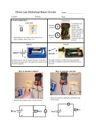
V<br />
mV<br />
Name:________________________<br />
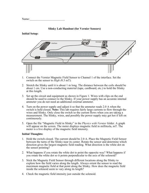
Initial Setup:<br />
<strong>Slinky</strong> <strong>Lab</strong> <strong>Handout</strong> (for Vernier Sensors)<br />
Interface<br />
Power supply<br />
Ammeter<br />
Switch<br />
1. Connect the Vernier Magnetic Field Sensor to Channel 1 of the interface. Set the<br />
switch on the sensor to High (0.3 mT).<br />
2. Stretch the <strong>Slinky</strong> until it is about 1 m long. The distance between the coils should be<br />
about 1 cm. Use a non-conducting material (tape, cardboard, etc.) to hold the <strong>Slinky</strong><br />
at this length.<br />
3. Set up the circuit and equipment as shown in Figure 1. Wires with clips on the end<br />
should be used to connect to the <strong>Slinky</strong>. If your power supply has an accurate internal<br />
ammeter you do not need an additional external ammeter.<br />
4. Turn on the power supply and adjust it so that the ammeter reads 2.0 A when the<br />
switch is held closed. Note: This lab requires fairly large currents to flow through the<br />
wires and <strong>Slinky</strong>. Only close the switch so the current flows when you are taking a<br />
measurement. The <strong>Slinky</strong>, wires, and possibly the power supply may get hot if left on<br />
continuously.<br />
5. Open the file “Magnetic Field in <strong>Slinky</strong>” in the Physics with Vernier folder. A graph<br />
will appear on the screen. The meter displays magnetic field in millitesla, mT. The<br />
meter is a live display of the magnetic field intensity.<br />
Initial Thoughts:<br />
1. Hold the switch closed. The current should be 2.0 A. Place the Magnetic Field Sensor<br />
between the turns of the <strong>Slinky</strong> near its center. Rotate the sensor and determine which<br />
direction gives the largest magnetic field reading. What direction is the white dot on<br />
the sensor pointing<br />
2. What happens if you rotate the white dot to point the opposite way What happens if<br />
you rotate the white dot so it points perpendicular to the axis of the solenoid<br />
3. Stick the Magnetic Field Sensor through different locations along the <strong>Slinky</strong> to<br />
explore how the field varies along the length. Always orient the sensor to read the<br />
maximum magnetic field at that point along the <strong>Slinky</strong>. How does the magnetic field<br />
inside the solenoid seem to vary along its length<br />
4. Check the magnetic field intensity just outside the solenoid.
Hall Probe and Solenoid Usage:<br />
1. Adjust the power supply so that the current will be 1.5 A when the switch is closed.<br />
2. With the Magnetic Field Sensor in position, but no current flowing, click<br />
to<br />
zero the sensor and remove readings due to the Earth’s magnetic field and any<br />
magnetism in the metal of the <strong>Slinky</strong>. Since the <strong>Slinky</strong> is made of an iron alloy, it can<br />
be magnetized itself. Moving the <strong>Slinky</strong> around can cause a change in the field, even<br />
if no current is flowing. This means you will need to zero the reading each time you<br />
move or adjust the <strong>Slinky</strong>.<br />
3. Click to begin data collection. Close and hold the switch for about 10 seconds<br />
during the data collection. As before, leave the switch closed only during actual data<br />
collection.<br />
4. View the field vs. time graph and determine where the current was flowing in the<br />
wire. Select this region on the graph by dragging over it. Find the average field while<br />
the current was on by clicking on the Statistics button, . Count the number of turns<br />
of the <strong>Slinky</strong> and measure its length. If you have any unstretched part of the <strong>Slinky</strong> at<br />
the ends, do not count it for either the turns or the length. Record the length of the<br />
<strong>Slinky</strong> and the average field in the data table.<br />
5. Repeat Steps 1 – 4 after changing the length of the <strong>Slinky</strong> various different lengths.<br />
Each time, zero the Magnetic Field Sensor with the current off. Make sure that the<br />
current remains at 1.5 A each time you turn it on.<br />
Your Job:<br />
Your lab group must design and execute an experiment to answer the following<br />
questions. Your experiment should record the field produced by the current for various<br />
lengths of the slinky. You should be careful to remember to use your knowledge of error<br />
analysis and reporting.<br />
1. What is the shape of the graph relating turns per unit length of the solenoid (slinky) to<br />
the magnetic field produced by the current Find an equation that fits the data for this<br />
graph. Should the equation produce a curve that passes through the origin Explain.<br />
2. What is the physical meaning of the coefficient(s) in your model Do they make<br />
sense Why<br />
3. What is the value of µ<br />
0<br />
(the permeability of free space) according to your<br />
experiment<br />
4. Does the current through the slinky have anything to do with the slope of your graph<br />
For example, if you increased the current to 3 Amps, how would your expect the new<br />
data to compare to your original graph<br />
5. How is this related to an MRI machine<br />
6. What have you learned during this experiment about creating a safe environment<br />
around an MRI machine<br />
The Report:<br />
Your report should begin with a clearly stated procedure. A reader should be able to<br />
recreate your experiment by following the steps listed. You do not need to spell out how<br />
to use the computer or hall probe. Turn in all your graphs and data by pasting directly<br />
from Excel into Word. Be sure to answer all of the questions in paragraph form.