Download - YT Industries
Download - YT Industries
Download - YT Industries

Create successful ePaper yourself
Turn your PDF publications into a flip-book with our unique Google optimized e-Paper software.
10<br />
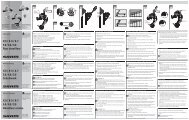
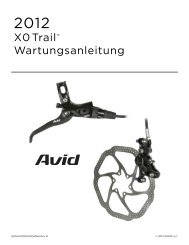
3.4.5 Wheel installation on a fork with QR 15 quick release<br />
axle (models Corsa, 44 and 33)<br />
CORSA 44 33<br />
Corsa, 44 and 33 models can be equipped with the QR15 wheel<br />
axle system.<br />
TheQR15 wheel axle system allows assembling and disassembling<br />
the front wheel in the fork in an extremely quick way and without<br />
the use of tools.<br />
The wheel locking procedure is as simple as the QR for standard<br />
wheels with a 9mm axle.<br />
For optimum fork performance, please follow the instructions below<br />
when installing the wheel:<br />
3.5 Fender installation<br />
• Place the wheel in between each fork.<br />
• Align the centre of the wheel between the two wheel axle clamps<br />
(see 6A of Picture 6).<br />
• Introduce the axle through the right wheel axle clamp.<br />
• Pass through the hole in the centre of the hub until it stops<br />
against the tightening nut of the axle that is installed in the left<br />
wheel axle clamp.<br />
6±1 Nm<br />
• By keeping the locking lever in parallel direction to the axis, screw<br />
7A 7B<br />
8 mm<br />
the axle in the nut or the nut in the axle (see 6B of Picture 6)<br />
without distinction. During the screwing operation, do not use the<br />
axle locking lever to increase the tightening torque.<br />
• By means of the check lever installed in the end of the axle, Picture 7 - Fender installation<br />
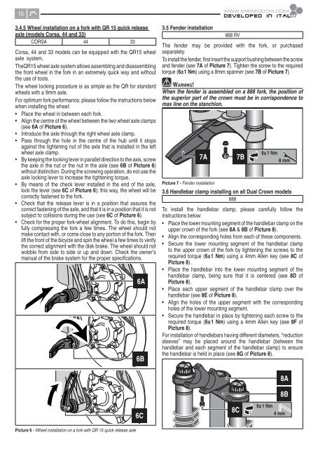
lock the lever (see 6C of Picture 6); this way, the wheel will be 3.6 Handlebar clamp installing on all Dual Crown models<br />
correctly fastened to the fork.<br />
888<br />
• Check that the release lever is in a position that assures the<br />
correct fastening of the axle, and that it is in a position that it is not To install the handlebar clamp, please carefully follow the<br />
subject to collisions during the use (see 6C of Picture 6). instructions below:<br />
• Check for the proper fork-wheel alignment. To do this, begin by • Place the lower mounting segment of the handlebar clamp on the<br />
fully compressing the fork a few times. The wheel should not upper crown of the fork (see 8A & 8B of Picture 8).<br />
make contact with, or come close to any portion of the fork. Then<br />
• Align the corresponding holes from each of these components.<br />
lift the front of the bicycle and spin the wheel a few times to verify<br />
the correct alignment with the disk brake. The wheel should not<br />
• Secure the lower mounting segment of the handlebar clamp<br />
wobble from side to side or up and down. Check the owner’s to the upper crown of the fork by tightening the screws to the<br />
manual of the brake system for the proper specifi cations. required torque (6±1 Nm) using a 4mm Allen key (see 8C of<br />
Picture 8).<br />
• Place the handlebar into the lower mounting segment of the<br />
handlebar clamp, being sure that it is centered (see 8D of<br />
6A Picture 8).<br />
• Place each upper segment of the handlebar clamp over the<br />
handlebar (see 8E of Picture 8).<br />
• Align the holes of the upper segment with the corresponding<br />
holes of the lower mounting segment.<br />
• Secure the handlebar in place by tightening each screw to the<br />
required torque (6±1 Nm) using a 4mm Allen key (see 8F of<br />
Picture 8).<br />
For installation of handlebars having different diameters, “reduction<br />
sleeves” may be placed around the handlebar (between the<br />
handlebar and each segment of the handlebar clamp) to ensure<br />
the handlebar is held in place (see 8G of Picture 8).<br />
6B<br />
888 RV<br />
The fender may be provided with the fork, or purchased<br />
separately.<br />
To install the fender, fi rst insert the support bushing between the screw<br />
and fender (see 7A of Picture 7). Tighten the screw to the required<br />
torque (6±1 Nm) using a 8mm spanner (see 7B of Picture 7).<br />
WARNING!<br />
When the fender is assembled on a 888 fork, the position of<br />
the superior part of the crown must be in corrispondence to<br />
max line on the stanchion.<br />
8A<br />
8B<br />
6C<br />
8C<br />
6±1 Nm<br />
4 mm<br />
Picture 6 - Wheel installation on a fork with QR 15 quick release axle