Installation and Operating Instructions - Crompton Instruments
Installation and Operating Instructions - Crompton Instruments
Installation and Operating Instructions - Crompton Instruments

You also want an ePaper? Increase the reach of your titles
YUMPU automatically turns print PDFs into web optimized ePapers that Google loves.
Summary of the new relay settings<br />
You should now have set the product as follows:<br />
Relay 1<br />
Trip Over Volts 59<br />
Caption 59<br />
Logged<br />
N<br />
Latched<br />
N<br />
Alarm<br />
Y<br />
Failsafe<br />
Y<br />
TripPoint 120.0<br />
Diff<br />
3.0 V<br />
TimeDelay<br />
1.0 Sec<br />
Testing Relay 1<br />
Now you are ready to test the relay Alarm function.<br />
With no measuring signal input, the relay should not be tripped. Confirm that Relay 1 contact is<br />
energised (Failsafe)<br />
Apply a variable AC voltage source to the input, <strong>and</strong> slowly increase the voltage.<br />
Note that the SPR is checking each phase for a voltage greater than 120 V.<br />
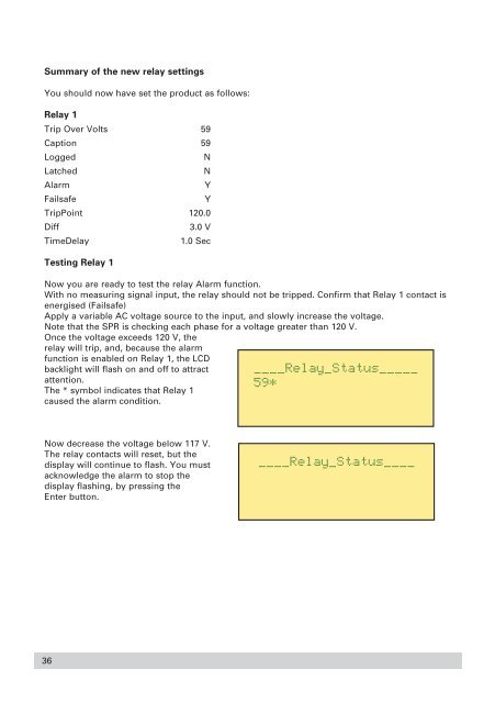
Once the voltage exceeds 120 V, the<br />
relay will trip, <strong>and</strong>, because the alarm<br />
function is enabled on Relay 1, the LCD<br />
backlight will flash on <strong>and</strong> off to attract<br />
attention.<br />
The * symbol indicates that Relay 1<br />
caused the alarm condition.<br />
Now decrease the voltage below 117 V.<br />
The relay contacts will reset, but the<br />
display will continue to flash. You must<br />
acknowledge the alarm to stop the<br />
display flashing, by pressing the<br />
Enter button.<br />
36