AD7843 Touch Screen Digitizer Data Sheet (REV. B) - mct.net
AD7843 Touch Screen Digitizer Data Sheet (REV. B) - mct.net
AD7843 Touch Screen Digitizer Data Sheet (REV. B) - mct.net

You also want an ePaper? Increase the reach of your titles
YUMPU automatically turns print PDFs into web optimized ePapers that Google loves.
FEATURES<br />
4-wire touch screen interface<br />
Specified throughput rate of 125 kSPS<br />
Low power consumption:<br />
1.37 mW max at 125 kSPS with VCC = 3.6 V<br />
Single supply, VCC of 2.2 V to 5.25 V<br />
Ratiometric conversion<br />
High speed serial interface<br />
Programmable 8-bit or 12-bit resolution<br />
2 auxiliary analog inputs<br />
Shutdown mode: 1 µA max<br />
16-lead QSOP and TSSOP packages<br />
APPLICATIONS<br />
Personal digital assistants<br />
Smart hand-held devices<br />
<strong>Touch</strong> screen monitors<br />
Point-of-sales terminals<br />
Pagers<br />
GENERAL DESCRIPTION<br />
The <strong>AD7843</strong> is a 12-bit successive approximation ADC with a<br />
synchronous serial interface and low on resistance switches for<br />
driving touch screens. The part operates from a single 2.2 V to<br />
5.25 V power supply and features throughput rates greater than<br />
125 kSPS.<br />
The external reference applied to the <strong>AD7843</strong> can be varied<br />
from 1 V to +VCC, while the analog input range is from 0 V to<br />
VREF. The device includes a shutdown mode that reduces the<br />
current consumption to less than 1 µA.<br />
The <strong>AD7843</strong> features on-board switches. This, coupled with low<br />
power and high speed operation, make this device ideal for<br />
battery-powered systems such as personal digital assistants with<br />
resistive touch screens, and other portable equipment. The part<br />
is available in a 16-lead 0.15" quarter size outline package<br />
(QSOP) and a 16-lead thin shrink small outline package<br />
(TSSOP).<br />
Rev. B<br />
Information furnished by Analog Devices is believed to be accurate and reliable.<br />
However, no responsibility is assumed by Analog Devices for its use, nor for any<br />
infringements of patents or other rights of third parties that may result from its use.<br />
Specifications subject to change without notice. No license is granted by implication<br />
or otherwise under any patent or patent rights of Analog Devices. Trademarks and<br />
registered trademarks are the property of their respective owners.<br />
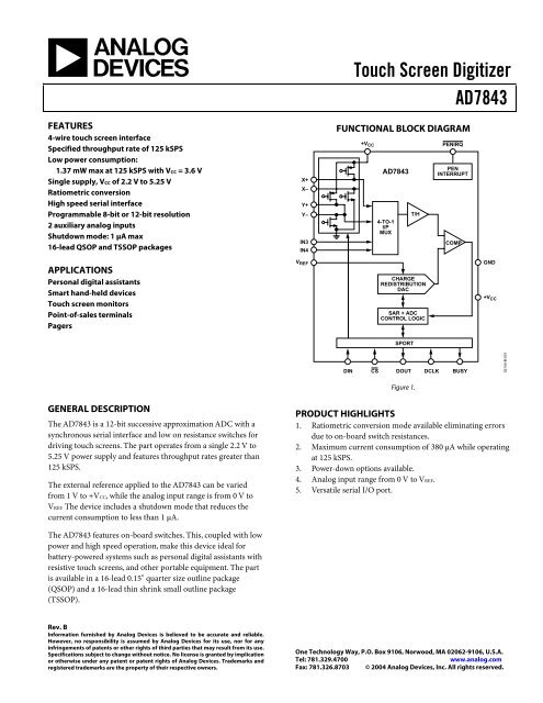
X+<br />
X–<br />
Y+<br />
Y–<br />
IN3<br />
IN4<br />
V REF<br />
<strong>Touch</strong> <strong>Screen</strong> <strong>Digitizer</strong><br />
<strong>AD7843</strong><br />
FUNCTIONAL BLOCK DIAGRAM<br />
+V CC<br />
<strong>AD7843</strong><br />
4-TO-1<br />
I/P<br />
MUX<br />
CHARGE<br />
REDISTRIBUTION<br />
DAC<br />
SAR + ADC<br />
CONTROL LOGIC<br />
SPORT<br />
PENIRQ<br />
PEN<br />
INTERRUPT<br />
DIN CS DOUT DCLK BUSY<br />
Figure 1.<br />
+V CC<br />
One Technology Way, P.O. Box 9106, Norwood, MA 02062-9106, U.S.A.<br />
Tel: 781.329.4700 www.analog.com<br />
Fax: 781.326.8703 © 2004 Analog Devices, Inc. All rights reserved.<br />
T/H<br />
COMP<br />
GND<br />
PRODUCT HIGHLIGHTS<br />
1. Ratiometric conversion mode available eliminating errors<br />
due to on-board switch resistances.<br />
2. Maximum current consumption of 380 µA while operating<br />
at 125 kSPS.<br />
3. Power-down options available.<br />
4. Analog input range from 0 V to VREF.<br />
5. Versatile serial I/O port.<br />
02144-B-001
<strong>AD7843</strong><br />
TABLE OF CONTENTS<br />
Specifications..................................................................................... 3<br />
Timing Specifications .................................................................. 4<br />
Absolute Maximum Ratings............................................................ 5<br />
ESD Caution.................................................................................. 5<br />
Pin Configuration and Function Descriptions............................. 6<br />
Terminology ...................................................................................... 7<br />
Typical Performance Characteristics ............................................. 8<br />
Circuit Information........................................................................ 11<br />
ADC Transfer Function............................................................. 11<br />
Typical Connection Diagram ................................................... 11<br />
<strong>REV</strong>ISION HISTORY<br />
3/04—<strong>Data</strong> <strong>Sheet</strong> Changed from Rev. A to Rev. B<br />
Updated Format..................................................................Universal<br />
Changes to Absolute Maximum Ratings ....................................... 5<br />
Addition to the PD0 and PD1 Section......................................... 14<br />
Additions to Ordering Guide........................................................ 20<br />
3/03—<strong>Data</strong> <strong>Sheet</strong> Changed from Rev. 0 to Rev. A<br />
Updated Outline Dimensions ....................................................... 16<br />
Rev. B | Page 2 of 20<br />
Analog Input ............................................................................... 12<br />
Control Register ......................................................................... 14<br />
Power vs. Throughput Rate....................................................... 15<br />
Serial Interface ............................................................................ 16<br />
Detailed Serial Interface Timing .............................................. 17<br />
Pen Interrupt Request................................................................ 19<br />
Grounding and Layout .............................................................. 19<br />
Outline Dimensions ....................................................................... 20<br />
Ordering Guide .......................................................................... 20
SPECIFICATIONS<br />
VCC = 2.7 V to 3.6 V, VREF = 2.5 V, fSCLK = 2 MHz, TA = −40°C to +85°C, unless otherwise noted.<br />
Table 1.<br />
Parameter <strong>AD7843</strong>A1 DC ACCURACY<br />
Unit Test Conditions/Comments<br />
Resolution 12 Bits<br />
No Missing Codes 11 Bits min<br />
Integral Nonlinearity2 ±2 LSB max<br />
Offset Error2 ±6 LSB max VCC = 2.7 V<br />
Offset Error Match3 1 LSB max<br />
0.1 LSB typ<br />
Gain Error2 ±4 LSB max<br />
Gain Error Match3 1 LSB max<br />
0.1 LSB typ<br />
Power Supply Rejection<br />
SWITCH DRIVERS<br />
On-Resistance<br />
70 dB typ<br />
2<br />
Y+, X+ 5 Ω typ<br />
Y−, X−<br />
ANALOG INPUT<br />
6 Ω typ<br />
Input Voltage Ranges 0 to VREF V<br />
DC Leakage Current ±0.1 µA typ<br />
Input Capacitance<br />
REFERENCE INPUT<br />
37 pF typ<br />
VREF Input Voltage Range 1.0/+VCC V min/max<br />
DC Leakage Current ±1 µA max<br />
VREF Input Impedance 5 GΩ typ CS = GND or +VCC<br />
VREF Input Current 3 20 µA max 8 µA typ<br />
1 µA typ fSAMPLE = 12.5 kHz<br />
1 µA max CS = +VCC; 0.001 µA typ<br />
LOGIC INPUTS<br />
Input High Voltage, VINH 2.4 V min<br />
Input Low Voltage, VINL 0.4 V max<br />
Input Current, IIN ±1 µA max Typically 10 nA, VIN = 0 V or +VCC<br />
Input Capacitance, CIN 4 10 pF max<br />
LOGIC OUTPUTS<br />
Output High Voltage, VOH VCC − 0.2 V min ISOURCE = 250 µA; VCC = 2.2 V to 5.25 V<br />
Output Low Voltage, VOL 0.4 V max ISINK = 250 µA<br />
PENIRQ Output Low Voltage, VOL 0.4 V max ISINK = 250 µA; 100 kW pull-up<br />
Floating-State Leakage Current ±10 µA max<br />
Floating-State Output Capacitance 4 10 pF max<br />
Output Coding Straight (Natural) Binary<br />
CONVERSION RATE<br />
Conversion Time 12 DCLK Cycles max<br />
Track-and-Hold Acquisition Time 3 DCLK Cycles min<br />
Throughput Rate 125 kSPS max<br />
Footnotes on next page.<br />
Rev. B | Page 3 of 20<br />
<strong>AD7843</strong>
<strong>AD7843</strong><br />
Parameter <strong>AD7843</strong>A 1 Unit Test Conditions/Comments<br />
POWER REQUIREMENTS<br />
VCC (Specified Performance) 2.7/3.6 V min/max Functional from 2.2 V to 5.25 V<br />
ICC 5 Digital I/Ps = 0 V or VCC<br />
Normal Mode (fSAMPLE = 125 kSPS) 380 µA max VCC = 3.6 V, 240 µA typ<br />
Normal Mode (fSAMPLE = 12.5 kSPS) 170 µA typ VCC = 2.7 V, fDCLK = 200 kHz<br />
Normal Mode (Static) 150 µA typ VCC = 3.6 V<br />
Shutdown Mode (Static) 1 µA max<br />
Power Dissipation 5<br />
Normal Mode (fSAMPLE = 125 kSPS) 1.368 mW max VCC = 3.6 V<br />
Shutdown 3.6 µW max VCC = 3.6 V<br />
1 Temperature range as follows: A Version: −40°C to +85°C.<br />
2 See the Terminology section.<br />
3 Guaranteed by design.<br />
4 Sample tested @ 25°C to ensure compliance.<br />
5 See the Power vs. Throughput Rate section.<br />
TIMING SPECIFICATIONS<br />
TA = TMIN to TMAX, unless otherwise noted; VCC = 2.7 V to 3.6 V, VREF = 2.5 V.<br />
Table 2. Timing Specifications1 Parameter Limit at TMIN, TMAX Unit Description<br />
fDCLK 2 10 kHz min<br />
2 MHz max<br />
tACQ 1.5 µs min Acquisition time<br />
t1 10 ns min CS falling edge to First DCLK rising edge<br />
t2 60 ns max CS falling edge to BUSY three-state disabled<br />
t3 60 ns max CS falling edge to DOUT three-state disabled<br />
t4 200 ns min DCLK high pulse width<br />
t5 200 ns min DCLK low pulse width<br />
t6 60 ns max DCLK falling edge to BUSY rising edge<br />
t7 10 ns min <strong>Data</strong> setup time prior to DCLK rising edge<br />
t8 10 ns min <strong>Data</strong> valid to DCLK hold time<br />
t9 3 200 ns max <strong>Data</strong> access time after DCLK falling edge<br />
t10 0 ns min CS rising edge to DCLK ignored<br />
t11 200 ns max CS rising edge to BUSY high impedance<br />
t12 4 200 ns max CS rising edge to DOUT high impedance<br />
1 Sample tested at 25°C to ensure compliance. All input signals are specified with tr = tf = 5 ns (10% to 90% of VCC) and are timed from a voltage level of 1.6 V.<br />
2 Mark/space ratio for the SCLK input is 40/60 to 60/40.<br />
3 Measured with the load circuit in Figure 2 and defined as the time required for the output to cross 0.4 V or 2.0 V.<br />
4 t12 is derived from the measured time taken by the data outputs to change 0.5 V when loaded with the circuit in Figure 2. The measured number is then extrapolated<br />
back to remove the effects of charging or discharging the 50 pF capacitor. This means that the time, t12, quoted in the timing characteristics is the true bus relinquish<br />
time of the part and is independent of the bus loading.<br />
TO<br />
OUTPUT<br />
PIN C L<br />
50pF<br />
200µA<br />
200µA<br />
I OL<br />
I OH<br />
Rev. B | Page 4 of 20<br />
1.6V<br />
Figure 2. Load Circuit for Digital Output Timing Specifications<br />
02144-B-002
ABSOLUTE MAXIMUM RATINGS<br />
TA = 25°C, unless otherwise noted.<br />
Table 3.<br />
Parameter Rating<br />
+VCC to GND −0.3 V to +7 V<br />
Analog Input Voltage to GND −0.3 V to VCC + 0.3 V<br />
Digital Input Voltage to GND −0.3 V to VCC + 0.3 V<br />
Digital Output Voltage to GND −0.3 V to VCC + 0.3 V<br />
VREF to GND −0.3 V to VCC + 0.3 V<br />
Input Current to Any Pin Except Supplies1 ±10 mA<br />
Operating Temperature Range<br />
Commercial −40°C to +85°C<br />
Storage Temperature Range −65°C to +150°C<br />
Junction Temperature 150°C<br />
QSOP, TSSOP Package, Power Dissipation 450 mW<br />
θJA Thermal Impedance 149.97°C/W (QSOP)<br />
150.4°C/W (TSSOP)<br />
θJC Thermal Impedance 38.8°C/W (QSOP)<br />
27.6°C/W (TSSOP)<br />
IR Reflow Soldering<br />
Peak Temperture<br />
Time-to-Peak Temperture<br />
Ramp-Down Rate<br />
Pb-free parts only<br />
Peak Temperture 250°C<br />
Time-to-Peak Temperture<br />
Ramp-Up Rate<br />
Ramp-Down Rate<br />
220°C (±5°C)<br />
10 sec to 30 sec<br />
6°C/sec max<br />
20 sec to 40 sec<br />
3°C/sec max<br />
6°C/sec max<br />
________________<br />
1 Transient currents of up to 100 mA do not cause SCR latch-up.<br />
Rev. B | Page 5 of 20<br />
<strong>AD7843</strong><br />
Stresses above those listed under Absolute Maximum Rating<br />
may cause permanent damage to the device. This is a stress<br />
rating only; functional operation of the device at these or any<br />
other conditions above those listed in the operational sections<br />
of this specification is not implied. Exposure to absolute<br />
maximum rating conditions for extended periods may affect<br />
device reliability.<br />
ESD CAUTION<br />
ESD (electrostatic discharge) sensitive device. Electrostatic charges as high as 4000 V readily accumulate on<br />
the human body and test equipment and can discharge without detection. Although this product features<br />
proprietary ESD protection circuitry, permanent damage may occur on devices subjected to high energy<br />
electrostatic discharges. Therefore, proper ESD precautions are recommended to avoid performance<br />
degradation or loss of functionality.
<strong>AD7843</strong><br />
PIN CONFIGURATION AND FUNCTION DESCRIPTIONS<br />
+VCC 1<br />
16 DCLK<br />
X+ 2<br />
15 CS<br />
Y+ 3<br />
14 DIN<br />
X– 4 <strong>AD7843</strong> 13 BUSY<br />
TOP VIEW<br />
Y– 5<br />
(Not to Scale) 12 DOUT<br />
GND 6<br />
11 PENIRQ<br />
IN3 7 10 +VCC IN4 8 9 VREF Figure 3. Pin Configuration QSOP/TSSOP<br />
Table 4. Pin Function Descriptions<br />
Pin No. Mnemonic Function<br />
1, 10 +VCC Power Supply Input. The +VCC range for the <strong>AD7843</strong> is from 2.2 V to 5.25 V. Both +VCC pins should be connected<br />
directly together.<br />
2 X+ X+ Position Input. ADC Input Channel 1.<br />
3 Y+ Y+ Position Input. ADC Input Channel 2.<br />
4 X− X− Position Input.<br />
5 Y− Y− Position Input.<br />
6 GND Analog Ground. Ground reference point for all circuitry on the <strong>AD7843</strong>. All analog input signals and any external<br />
reference signal should be referred to this GND voltage.<br />
7 IN3 Auxiliary Input 1. ADC Input Channel 3.<br />
8 IN4 Auxiliary Input 2. ADC Input Channel 4.<br />
9 VREF Reference Input for the <strong>AD7843</strong>. An external reference must be applied to this input. The voltage range for the<br />
external reference is 1.0 V to +VCC. For specified performance, it is 2.5 V.<br />
11 PENIRQ Pen Interrupt. CMOS logic open-drain output (requires 10 kΩ to 100 kΩ pull-up register externally).<br />
12 DOUT <strong>Data</strong> Out. Logic Output. The conversion result from the <strong>AD7843</strong> is provided on this output as a serial data stream.<br />
The bits are clocked out on the falling edge of the DCLK input. This output is high impedance when CS is high.<br />
13 BUSY BUSY Output. Logic Output. This output is high impedance when CS is high.<br />
14 DIN <strong>Data</strong> In. Logic input. <strong>Data</strong> to be written to the <strong>AD7843</strong> control register is provided on this input and is clocked into<br />
the register on the rising edge of DCLK (see the Control Register section).<br />
15 CS Chip Select Input. Active Low Logic Input. This input provides the dual function of initiating conversions on the<br />
<strong>AD7843</strong> and also enables the serial input/output register.<br />
16 DCLK External Clock Input. Logic Input. DCLK provides the serial clock for accessing data from the part. This clock input<br />
is also used as the clock source for the <strong>AD7843</strong> conversion process.<br />
Rev. B | Page 6 of 20<br />
02144-B-003
TERMINOLOGY<br />
Integral Nonlinearity<br />
This is the maximum deviation from a straight line passing<br />
through the endpoints of the ADC transfer function. The<br />
endpoints of the transfer function are zero scale, a point 1 LSB<br />
below the first code transition, and full scale, a point 1 LSB<br />
above the last code transition.<br />
Differential Nonlinearity<br />
This is the difference between the measured and the ideal 1 LSB<br />
change between any two adjacent codes in the ADC.<br />
Offset Error<br />
This is the deviation of the first code transition (00…000) to<br />
(00…001) from the ideal, that is, AGND + 1 LSB.<br />
Gain Error<br />
This is the deviation of the last code transition (111…110) to<br />
(111…111) from the ideal (VREF − 1 LSB) after the offset error<br />
has been adjusted out.<br />
Rev. B | Page 7 of 20<br />
<strong>AD7843</strong><br />
Track-and-Hold Acquisition Time<br />
The track-and-hold amplifier enters the acquisition phase on<br />
the fifth falling edge of DCLK after the START bit has been<br />
detected. Three DCLK cycles are allowed for the track-and-hold<br />
acquisition time. The input signal is fully acquired to the 12-bit<br />
level within this time even with the maximum specified DCLK<br />
frequency. See the Analog Input section for more details.<br />
On Resistance<br />
This is a measure of the ohmic resistance between the drain and<br />
source of the switch drivers.
<strong>AD7843</strong><br />
TYPICAL PERFORMANCE CHARACTERISTICS<br />
SUPPLY CURRENT (µA)<br />
SUPPLY CURRENT (µA)<br />
DELTA FROM +25°C (LSB)<br />
207<br />
206<br />
205<br />
204<br />
203<br />
202<br />
201<br />
200<br />
199<br />
198<br />
–40 –20 0 20 40 60 80 100<br />
TEMPERATURE (°C)<br />
230<br />
220<br />
210<br />
200<br />
190<br />
180<br />
170<br />
160<br />
Figure 4. Supply Current vs. Temperature<br />
f SAMPLE = 12.5kHz<br />
V REF = +V CC<br />
150<br />
2.2 2.6 3.0 3.4 3.8 4.2 4.6 5.0<br />
+VCC (V)<br />
0.20<br />
0.15<br />
0.10<br />
0.05<br />
0<br />
–0.05<br />
–0.10<br />
–0.15<br />
Figure 5. Supply Current vs. +VCC<br />
–0.20<br />
–40 –20 0 20 40 60 80 100<br />
TEMPERATURE (°C)<br />
Figure 6. Change in Gain vs. Temperature<br />
02144-B-004<br />
02144-B-005<br />
02144-B-006<br />
SUPPLY CURRENT (nA)<br />
SAMPLE RATE (kSPS)<br />
DELTA FROM +25°C (LSB)<br />
Rev. B | Page 8 of 20<br />
141<br />
140<br />
139<br />
138<br />
137<br />
136<br />
135<br />
134<br />
–40 –20 0 20 40 60 80 100<br />
TEMPERATURE (°C)<br />
1000<br />
Figure 7. Power-Down Supply Current vs. Temperature<br />
V REF = +V CC<br />
100<br />
2.2 2.7 3.2 3.7 4.2 4.7 5.2<br />
+VCC (V) 02144-B-008<br />
0.6<br />
0.4<br />
0.2<br />
0<br />
–0.2<br />
–0.4<br />
Figure 8. Maximum Sample Rate vs. +VCC<br />
–0.6<br />
–40 –20 0 20 40 60 80 100<br />
TEMPERATURE (°C)<br />
Figure 9. Change in Offset vs. Temperature<br />
02144-B-007<br />
02144-B-009
REFERENCE CURRENT (µA)<br />
R ON (Ω)<br />
ERROR (LSB)<br />
7.5<br />
6.5<br />
5.5<br />
4.5<br />
3.5<br />
2.5<br />
1.5<br />
0.5<br />
10 25 40 55 70 85 100 115 130<br />
SAMPLE RATE (kHz) 02144-B-010<br />
10<br />
9<br />
8<br />
7<br />
6<br />
5<br />
Y+<br />
Figure 10. Reference Current vs. Sample Rate<br />
X+<br />
X–<br />
Y–<br />
4<br />
2.0 2.5 3.0 3.5 4.0 4.5 5.0 5.5<br />
+VCC (V)<br />
2.0<br />
1.8<br />
1.6<br />
1.4<br />
1.2<br />
1.0<br />
0.8<br />
0.6<br />
0.4<br />
0.2<br />
Figure 11. Switch-On Resistance vs. +VCC<br />
(X+, Y+: +VCC to Pin; X−, Y−: Pin to GND)<br />
INL: R = 500Ω<br />
DNL: R = 2kΩ<br />
DNL: R = 500Ω<br />
INL: R = 2kΩ<br />
0<br />
15 35 55 75 95 115 135 155 175 195<br />
SAMPLING RATE (kSPS) 02144-B-012<br />
Figure 12. Maximum Sampling Rate vs. RIN<br />
02144-B-011<br />
REFERENCE CURRENT (µA)<br />
R ON (Ω)<br />
SNR (dB)<br />
Rev. B | Page 9 of 20<br />
<strong>AD7843</strong><br />
02144-B-013<br />
14<br />
13<br />
12<br />
11<br />
10<br />
9<br />
8<br />
7<br />
6<br />
5<br />
4<br />
3<br />
2<br />
–40 –20 0 20 40 60 80<br />
TEMPERATURE (°C)<br />
9<br />
8<br />
7<br />
6<br />
5<br />
4<br />
Figure 13. Reference Current vs. Temperature<br />
Y–<br />
3<br />
–40 –20 0 20 40 60 80 100<br />
TEMPERATURE (°C)<br />
0<br />
20<br />
40<br />
60<br />
80<br />
100<br />
Y+<br />
Figure 14. Switch-On Resistance vs. Temperature<br />
(X+, Y+:+VCC to Pin; X−, Y−: Pin to GND)<br />
120<br />
0 7.5 15.0 22.5 30.0 37.5 45.0 52.5 60.0<br />
FREQUENCY (kHz) 02144-B-015<br />
X–<br />
X+<br />
f SAMPLE = 125kHz<br />
f IN = 15kHz<br />
SNR = 68.34dB<br />
Figure 15. Auxiliary Channel Dynamic Performance<br />
(fSAMPLE =125 kHz, fINPUT = 15 kHz)<br />
02144-B-014
<strong>AD7843</strong><br />
PSRR (dB)<br />
0<br />
–20<br />
–40<br />
–60<br />
–80<br />
–100<br />
–120<br />
V CC = 3V, V REF = 2.5V<br />
100mV p-p SINEWAVE ON +V CC<br />
f SAMPLE = 125kHz, f IN = 20kHz<br />
0 10 20 30 40 50 60 70 80 90 100<br />
VCC RIPPLE FREQUENCY (kHz) 02144-B-016<br />
Figure 16. AC PSRR vs. Supply Ripple Frequency<br />
Rev. B | Page 10 of 20<br />
Figure 16 shows the power supply rejection ratio versus VCC<br />
supply frequency for the <strong>AD7843</strong>. The power supply rejection<br />
ratio is defined as the ratio of the power in the ADC output at<br />
full-scale frequency fS to the power of a 100 mV sine wave<br />
applied to the ADC VCC supply of frequency fS:<br />
where:<br />
PSRR (dB) = 10 log (Pf/Pfs)<br />
Pf is the power at frequency f in ADC output.<br />
Pfs is the power at frequency fS coupled onto the ADC VCC<br />
supply.<br />
Here a 100 mV p-p sine wave is coupled onto the VCC supply.<br />
Decoupling capacitors of 10 µF and 0.1 µF were used on the<br />
supply.
CIRCUIT INFORMATION<br />
The <strong>AD7843</strong> is a fast, low-power, 12-bit, single-supply, A/D<br />
converter. The <strong>AD7843</strong> can be operated from a 2.2 V to 5.25 V<br />
supply. When operated from either a 5 V supply or a 3 V supply,<br />
the <strong>AD7843</strong> is capable of throughput rates of 125 kSPS when<br />
provided with a 2 MHz clock.<br />
The <strong>AD7843</strong> provides the user with an on-chip track-and-hold,<br />
multiplexer, ADC, and serial interface housed in tiny 16-lead<br />
QSOP or TSSOP packages, which offer the user considerable<br />
space-saving advantages over alternative solutions. The serial<br />
clock input (DCLK) accesses data from the part and also provides<br />
the clock source for the successive approximation ADC. The<br />
analog input range is 0 V to VREF (where the externally-applied<br />
VREF can be between 1 V and VCC).<br />
The analog input to the ADC is provided via an on-chip<br />
multiplexer. This analog input can be any one of the X and Y<br />
panel coordinates. The multiplexer is configured with low<br />
resistance switches that allow an unselected ADC input channel<br />
to provide power and an accompanying pin to provide ground<br />
for an external device. For some measurements, the on resistance<br />
of the switches could present a source of error. However, with a<br />
differential input to the converter and a differential reference<br />
architecture, this error can be negated.<br />
ADC TRANSFER FUNCTION<br />
The output coding of the <strong>AD7843</strong> is straight binary. The<br />
designed code transitions occur at successive integer LSB values<br />
(that is, 1 LSB, 2 LSBs, and so forth.). The LSB size equals<br />
VREF/4096. The ideal transfer characteristic for the <strong>AD7843</strong> is<br />
shown in Figure 17.<br />
TOUCH<br />
SCREEN<br />
1µF TO 10µF<br />
(OPTIONAL)<br />
AUXILIARY INPUTS<br />
2.2V TO 5V<br />
0.1µF<br />
ADC CODE<br />
Rev. B | Page 11 of 20<br />
111...111<br />
111...110<br />
111...000<br />
011...111<br />
1 +VCC DCLK 16<br />
2 X+<br />
<strong>AD7843</strong><br />
CS 15<br />
3 Y+<br />
DIN 14<br />
4 X– BUSY 13<br />
5 Y– DOUT 12<br />
6 GND PENIRQ 11<br />
7 IN3 +VCC 10<br />
8 IN4 VREF 9<br />
000...010<br />
000...001<br />
000...000<br />
1LSB<br />
0V<br />
Figure 18. Typical Application Circuit<br />
1LSB = V REF /4096<br />
+VREF –1LSB<br />
ANALOG INPUT<br />
Figure 17. <strong>AD7843</strong> Transfer Characteristic<br />
02144-B-017<br />
<strong>AD7843</strong><br />
TYPICAL CONNECTION DIAGRAM<br />
Figure 18 shows a typical connection diagram for the <strong>AD7843</strong><br />
in a touch screen control application. The <strong>AD7843</strong> requires an<br />
external reference and an external clock. The external reference<br />
can be any voltage between 1 V and VCC. The value of the<br />
reference voltage sets the input range of the converter. The<br />
conversion result is output MSB first, followed by the remaining<br />
11 bits and three trailing zeroes, depending on the number of<br />
clocks used per conversion. (See the Serial Interface section.)<br />
For applications where power consumption is a concern, the<br />
power management option should be used to improve power<br />
performance. See Table 7 for the available power management<br />
options.<br />
0.1µF<br />
SERIAL/CONVERSION CLOCK<br />
CHIP SELECT<br />
SERIAL DATA IN<br />
CONVERTER STATUS<br />
SERIAL DATA OUT<br />
PEN INTERRUPT<br />
100kΩ<br />
(OPTIONAL)<br />
02144-B-018
<strong>AD7843</strong><br />
ANALOG INPUT<br />
Figure 19 shows an equivalent circuit of the analog input<br />
structure of the <strong>AD7843</strong>, which contains a block diagram of the<br />
input multiplexer, the differential input of the ADC, and the<br />
differential reference.<br />
Table 5 shows the multiplexer address corresponding to each<br />
analog input, both for the SER/DFR bit in the control register<br />
set high and low. The control bits are provided serially to the<br />
device via the DIN pin. For more information on the control<br />
register, see the Control Register section.<br />
When the converter enters hold mode, the voltage difference<br />
between the +IN and −IN inputs (see Figure 19) is captured on<br />
the internal capacitor array. The input current on the analog<br />
inputs depends on the conversion rate of the device. During the<br />
sample period, the source must charge the internal sampling<br />
capacitor (typically 37 pF). Once the capacitor is fully charged,<br />
there is no further input current. The rate of charge transfer<br />
from the analog source to the converter is a function of<br />
conversion rate.<br />
X+<br />
Y+<br />
IN3<br />
IN4<br />
V CC<br />
ON-CHIP SWITCHES<br />
4-TO-1<br />
MUX<br />
X+<br />
X–<br />
Y+<br />
Y–<br />
IN+<br />
IN+<br />
X+ Y+<br />
Rev. B | Page 12 of 20<br />
Acquisition Time<br />
The track-and-hold amplifier enters tracking mode on the<br />
falling edge of the fifth DCLK after the START bit us detected<br />
(see Figure 24). The time required for the track-and-hold<br />
amplifier to acquire an input signal depends on how quickly the<br />
37 pF input capacitance is charged. With zero source impedance<br />
on the analog input, three DCLK cycles are always sufficient to<br />
acquire the signal to the 12-bit level. With a source impedance<br />
RIN on the analog input, the actual acquisition time required is<br />
calculated using the formula:<br />
t<br />
ACQ<br />
( R + 100 Ω)<br />
37 pF<br />
= 8 . 4 × IN ×<br />
where RIN is the source impedance of the input signal and 100 Ω<br />
and 37 pF is the input RC value. Depending on the frequency of<br />
DCLK used, three DCLK cycles may or may not be sufficient to<br />
acquire the analog input signal with various source impedance<br />
values.<br />
3-TO-1<br />
MUX<br />
3-TO-1<br />
MUX<br />
REF<br />
EXT<br />
REF+<br />
ADC CORE DATA OUT<br />
IN– REF–<br />
X– Y– GND<br />
Figure 19. Equivalent Analog Input Circuit<br />
Table 5. Analog Input, Reference, and <strong>Touch</strong> <strong>Screen</strong> Control<br />
A21 A11 A01 SER/DFR Analog Input X Switches Y Switches +REF2 –REF2 0 0 1 1 X+ OFF ON VREF GND<br />
0 1 0 1 IN3 OFF OFF VREF GND<br />
1 0 1 1 Y+ ON OFF VREF GND<br />
1 1 0 1 IN4 OFF OFF VREF GND<br />
0 0 1 0 X+ OFF ON Y+ Y−<br />
1 0 1 0 Y+ ON OFF X+ X−<br />
1 1 0 0 Outputs Identity Code, 1000 0000 0000<br />
1 All remaining configurations are invalid addresses.<br />
2 Internal node − not directly accessible by the user.<br />
02144-B-019
<strong>Touch</strong> <strong>Screen</strong> Settling<br />
In some applications, external capacitors could be required<br />
across the touch screen to filter noise associated with it, for<br />
example, noise generated by the LCD panel or backlight<br />
circuitry. The value of these capacitors causes a settling time<br />
requirement when the panel is touched. The settling time<br />
typically appears as a gain error. There are several methods for<br />
minimizing or eliminating this issue. The problem could be that<br />
the input signal, reference, or both have not settled to their final<br />
value before the sampling instant of the ADC. Additionally, the<br />
reference voltage could still be changing during the conversion<br />
cycle. One option is to stop, or slow down the DCLK for the<br />
required touch screen settling time. This allows the input and<br />
reference to stabilize for the acquisition time, which resolves the<br />
issue for both single-ended and differential modes.<br />
The other option is to operate the <strong>AD7843</strong> in differential mode<br />
only for the touch screen and to program the <strong>AD7843</strong> to keep<br />
the touch screen drivers on and not go into power-down (PD0<br />
= PD1 = 1). Several conversions might be required, depending<br />
on the settling time required and the <strong>AD7843</strong> data rate. Once<br />
the required number of conversions are made, the <strong>AD7843</strong> can<br />
then be placed into a power-down state on the last<br />
measurement. The last method is to use the 15 DCLK cycle<br />
mode, which maintains the touch screen drivers on until it is<br />
commanded to stop by the processor.<br />
Reference Input<br />
The voltage difference between +REF and −REF (see Figure 19)<br />
sets the analog input range. The <strong>AD7843</strong> operates with a reference<br />
input in the range of 1 V to VCC. The voltage into the VREF<br />
input is not buffered and directly drives the capacitor DAC<br />
portion of the <strong>AD7843</strong>. Figure 20 shows the reference input<br />
circuitry. Typically, the input current is 8 µA with VREF = 2.5 V<br />
and fSAMPLE = 125 kHz. This value varies by a few microamps,<br />
depending on the result of the conversion. The reference current<br />
diminishes directly with both conversion rate and reference<br />
voltage. As the current from the reference is drawn on each bit<br />
decision, clocking the converter more quickly during a given<br />
conversion period does not reduce the overall current drain<br />
from the reference.<br />
V REF<br />
X+<br />
Y+<br />
3-TO-1<br />
MUX<br />
ADC<br />
Figure 20. Reference Input Circuitry<br />
When making touch screen measurements, conversions can be<br />
made in the differential (ratiometric) mode or the single-ended<br />
mode. If the SER/DFR bit is set to 1 in the control register, a<br />
single-ended conversion is performed. Figure 21 shows the<br />
configuration for a single-ended Y-coordinate measurement.<br />
The X+ input is connected to the analog to digital converter, the<br />
Y+ and Y− drivers are turned on, and the voltage on X+ is<br />
digitized. The conversion is performed with the ADC referenced<br />
from GND to VREF. The advantage of this mode is that the<br />
02144-B-020<br />
Rev. B | Page 13 of 20<br />
<strong>AD7843</strong><br />
switches that supply the external touch screen can be turned off<br />
once the acquisition is complete, resulting in a power saving.<br />
However, the on resistance of the Y drivers affects the input<br />
voltage that can be acquired. The full touch screen resistance<br />
may be in the order of 200 Ω to 900 Ω, depending on the manufacturer.<br />
Therefore if the on resistance of the switches is<br />
approximately 6 Ω, true full-scale and zero-scale voltages cannot<br />
be acquired regardless of where the pen/stylus is on the touch<br />
screen. Note that the minimum touch screen resistance<br />
recommended for use with the <strong>AD7843</strong> is approximately 70 Ω.<br />
GND<br />
Y+<br />
Y–<br />
+V CC<br />
X+ IN+<br />
V REF<br />
REF+<br />
IN+ ADC CORE<br />
IN– REF–<br />
Figure 21. Single-Ended Reference Mode (SER/DFR = 1)<br />
In this mode of operation, therefore, some voltage is likely to be<br />
lost across the internal switches and, in addition to this, it is<br />
unlikely that the internal switch resistance will track the resistance<br />
of the touch screen over temperature and supply, providing<br />
an additional source of error.<br />
The alternative to this situation is to set the SER/DFR bit low. If<br />
one again considers making a Y-coordinate measurement, but<br />
now the +REF and −REF nodes of the ADC are connected<br />
directly to the Y+ and Y− pins, this means the analog-to-digital<br />
conversion is ratiometric. The result of the conversion is always<br />
a percentage of the external resistance, independent of how it<br />
could change with respect to the on resistance of the internal<br />
switches. Figure 22 shows the configuration for a ratiometric Ycoordinate<br />
measurement. It should be noted that the differential<br />
reference mode can be used only with +VCC since the source of<br />
the +REF voltage and cannot be used with VREF.<br />
The disadvantage of this mode of operation is that during both<br />
the acquisition phase and conversion process, the external touch<br />
screen must remain powered. This results in additional supply<br />
current for the duration of the conversion.<br />
GND<br />
Y+<br />
Y–<br />
+V CC<br />
X+ IN+<br />
REF+<br />
IN+ ADC CORE<br />
IN– REF–<br />
Figure 22. Differential Reference Mode (SER/DFR = 0)<br />
02144-B-022<br />
02144-B-021
<strong>AD7843</strong><br />
CONTROL REGISTER<br />
The control word provided to the ADC via the DIN pin is<br />
shown in Table 6. This provides the conversion start, channel<br />
addressing, ADC conversion resolution, configuration, and<br />
power-down of the <strong>AD7843</strong>.<br />
Table 6 provides detailed information on the order and<br />
description of these control bits within the control word.<br />
Initiate START<br />
The first bit, the S bit, must always be set to 1 to initiate the start<br />
of the control word. The <strong>AD7843</strong> ignores any inputs on the DIN<br />
line until the START bit is detected.<br />
Channel Addressing<br />
The next three bits in the control register, A2, A1, and A0, select<br />
the active input channel(s) of the input multiplexer (see Table 5<br />
and Figure 19), touch screen drivers, and the reference inputs.<br />
MODE<br />
The MODE bit sets the resolution of the analog to digital<br />
converter. With 0 in this bit, the following conversion has 12 bits<br />
of resolution. With 1 in this bit, the following conversion has 8<br />
bits of resolution.<br />
SER/DFR<br />
The SER/DFR bit controls the reference mode, which can be<br />
either single-ended or differential if 1 or 0 is written to this bit,<br />
respectively. The differential mode is also referred to as the<br />
ratiometric conversion mode. This mode is optimum for<br />
X-position and Y-position measurements. The reference is<br />
Rev. B | Page 14 of 20<br />
derived from the voltage at the switch drivers, which is almost<br />
the same as the voltage to the touch screen. In this case, a<br />
separate reference voltage is not needed because the reference<br />
voltage to the ADC is the voltage across the touch screen. In<br />
single-ended mode, the reference voltage to the converter is<br />
always the difference between the VREF and GND pins. See<br />
Table 5 and Figure 19 through Figure 22 for further<br />
information.<br />
Because the supply current required by the device is so low, a<br />
precision reference can be used as the supply source to the<br />
<strong>AD7843</strong>. It may also be necessary to power the touch screen<br />
from the reference, which could require 5 mA to 10 mA. A<br />
REF19x voltage reference can source up to 30 mA and, as such,<br />
could supply both the ADC and the touch screen. Care must be<br />
taken, however, to ensure that the input voltage applied to the<br />
ADC does not exceed the reference voltage and therefore the<br />
supply voltage. See the Absolute Maximum Ratings section.<br />
Note that the differential mode can only be used for X-position<br />
and Y-Position measurements. All other measurements require<br />
single-ended mode.<br />
PD0 and PD1<br />
The power management options are selected by programming<br />
the power management bits, PD0 and PD1, in the control<br />
register. Table 7 summarizes the available options. On power-up,<br />
PD0 defaults to 0, while PD1 defaults to 1..<br />
Table 6. Control Register Bit Function Description<br />
MSB LSB<br />
S A2 A1 A0 MODE SER/DFR PD1 PD0<br />
Bit Mnemonic Comment<br />
7 S Start Bit. The control word starts with the first high bit on DIN. A new control word can start every 15th DCLK cycle<br />
when in the 12-bit conversion mode, or every 11th DCLK cycle when in 8-bit conversion mode.<br />
6–4 A2–A0 Channel Select Bits. These three address bits, along with the SER/DFR bit, control the setting of the multiplexer input,<br />
switches, and reference inputs, as described in Table 5.<br />
3 MODE 12-Bit/8-Bit Conversion Select Bit. This bit controls the resolution of the following conversion. With 0 in this bit, the<br />
conversion has a 12-bit resolution, or with 1 in this bit, the conversion has a 8-bit resolution.<br />
2 SER/DFR Single-Ended/Differential Reference Select Bit. Along with Bits A2–A0, this bit controls the setting of the multiplexer<br />
input, switches, and reference inputs, as described in Table 5.<br />
1, 0 PD1, PD0 Power Management Bits. These two bits decode the power-down mode of the <strong>AD7843</strong>, as shown in Table 7.
POWER VS. THROUGHPUT RATE<br />
By using the power-down options on the <strong>AD7843</strong> when not<br />
converting, the average power consumption of the device<br />
decreases at lower throughput rates. Figure 23 shows how, as the<br />
throughput rate is reduced while maintaining the DCLK<br />
frequency at 2 MHz, the device remains in its power-down state<br />
longer and the average current consumption over time drops<br />
accordingly.<br />
For example, if the <strong>AD7843</strong> is operated in a 24 DCLK<br />
continuous sampling mode, with a throughput rate of 10 kSPS<br />
and a SCLK of 2 MHz, and the device is placed in the powerdown<br />
mode between conversions, (PD0, PD1 = 0, 0), the current<br />
consumption is calculated as follows. The power dissipation<br />
during normal operation is typically 210 µA (VCC = 2.7 V). The<br />
power-up time of the ADC is instantaneous, so when the part is<br />
converting, it consumes 210 µA. In this mode of operation, the<br />
part powers up on the fourth falling edge of DCLK after the<br />
start bit is recognized. It goes back into power-down at the end<br />
of conversion on the 20th falling edge of DCLK. This means the<br />
part consumes 210 µA for 16 DCLK cycles only, 8 µs, during<br />
each conversion cycle. With a throughput rate of 10 kSPS, the<br />
cycle time is 100 µs and the average power dissipated during<br />
each cycle is (8/100) × (210 µA) = 16.8 µA.<br />
Table 7. Power Management Options<br />
PD1 PD0 PENIRQ Description<br />
SUPPLY CURRENT (µA)<br />
Rev. B | Page 15 of 20<br />
1000<br />
100<br />
10<br />
f DCLK = 16 × f SAMPLE<br />
f DCLK = 2MHz<br />
V CC = 2.7V<br />
T A = –40°C TO +95°C<br />
<strong>AD7843</strong><br />
1<br />
0 20 40 60 80 100 120<br />
THROUGHPUT (kSPS) 02144-B-023<br />
Figure 23. Supply Current vs. Throughput (µA)<br />
0 0 Enabled This configuration results in power-down of the device between conversions. The <strong>AD7843</strong> only powers down<br />
between conversions. Once PD1 and PD0 are set to 0, 0, the conversion is performed first, and the <strong>AD7843</strong><br />
powers down upon completion of that conversion. At the start of the next conversion, the ADC instantly powers<br />
up to full power. This means there is no need for additional delays to ensure full operation, and the very first<br />
conversion is valid. The Y− switch is on while in power-down.<br />
0 1 Disabled This configuration results in the same behavior as when PD1 and PD0 have been programmed with 0, 0, except<br />
that PENIRQ is disabled. The Y− switch is off while in power-down.<br />
1 0 Enabled This configuration results in keeping the <strong>AD7843</strong> permanently powered up with PENIRQ enabled.<br />
1 1 Disabled This configuration results in keeping the <strong>AD7843</strong> always powered up with PENIRQ disabled.
<strong>AD7843</strong><br />
SERIAL INTERFACE<br />
Figure 24 shows the typical operation of the serial interface of<br />
the <strong>AD7843</strong>. The serial clock provides the conversion clock and<br />
also controls the transfer of information to and from the<br />
<strong>AD7843</strong>. One complete conversion can be achieved with 24<br />
DCLK cycles.<br />
The CS signal initiates the data transfer and conversion process.<br />
The falling edge of CS takes the BUSY output and the serial bus<br />
out of three-state. The first eight DCLK cycles are used to write<br />
to the control register via the DIN pin. The control register is<br />
updated in stages as each bit is clocked in. Once the converter<br />
has enough information about the following conversion to set<br />
the input multiplexer and switches appropriately, the converter<br />
enters acquisition mode and, if required, the internal switches<br />
are turned on. During the acquisition mode, the reference input<br />
data is updated. After the three DCLK cycles of acquisition, the<br />
CS<br />
DCLK<br />
DIN<br />
BUSY<br />
DOUT<br />
X/Y SWITCHES 1<br />
(SER/DFR HIGH)<br />
X/Y SWITCHES 1,2<br />
(SER/DFR LOW)<br />
OFF ON<br />
OFF<br />
Rev. B | Page 16 of 20<br />
control word is complete (the power management bits are now<br />
updated) and the converter enters conversion mode. At this<br />
point, track-and-hold goes into hold mode, the input signal is<br />
sampled, and the BUSY output goes high (BUSY returns low on<br />
the next falling edge of DCLK). The internal switches may also<br />
turn off at this point if in single-ended mode.<br />
The next 12 DCLK cycles are used to perform the conversion<br />
and to clock out the conversion result. If the conversion is<br />
ratiometric (SER/DFR set low), the internal switches are on<br />
during the conversion. A 13th DCLK cycle is needed to allow<br />
the DSP/microcontroller to clock in the LSB. Three more DCLK<br />
cycles clock out the three trailing zeroes and complete the 24<br />
DCLK transfer. The 24 DCLK cycles can be provided from a<br />
DSP or via three bursts of 8 clock cycles from a microcontroller.<br />
S A2 A1 A0 MODE PD1 PD0<br />
(START) IDLE<br />
ACQUIRE CONVERSION IDLE<br />
THREE-STATE<br />
THREE-STATE<br />
SER/<br />
DFR<br />
THREE-STATE<br />
t ACQ<br />
1 8 1<br />
8 1<br />
8<br />
11 10 9 8 7 6 5 4 3 2 1 0<br />
THREE-STATE<br />
ZERO FILLED<br />
(MSB) (LSB)<br />
OFF ON<br />
OFF<br />
NOTES<br />
1 Y DRIVERS ARE ON WHEN X+ IS SELECTED INPUT CHANNEL (A2–A0 = 001); X DRIVERS ARE ON WHEN Y+ IS SELECTED INPUT CHANNEL (A2–A0 = 101).<br />
1 WHEN PD1, PD0 = 10 OR 00, Y– WILL TURN ON AT THE END OF THE CONVERSION.<br />
2DRIVERS WILL REMAIN ON IF POWER-DOWN MODE IS 11 (NO POWER-DOWN) UNTIL SELECTED INPUT CHANNEL, REFERENCE MODE,<br />
1 OR POWER-DOWN MODE IS CHANGED.<br />
Figure 24. Conversion Timing, 24 DCLKS per Conversion Cycle, 8-Bit Bus Interface. No DCLK delay required with dedicated serial port.<br />
02144-B-024
DETAILED SERIAL INTERFACE TIMING<br />
Figure 25 shows the detailed timing diagram for serial<br />
interfacing to the <strong>AD7843</strong>. Writing information to the control<br />
register takes place on the first eight rising edges of DCLK in a<br />
data transfer. The control register is written to only if a START<br />
bit is detected (see the Control Register section) on DIN. The<br />
initiation of the following conversion also depends on the<br />
presence of the START bit. Throughout the eight DCLK cycles<br />
when data is being written to the part, the DOUT line is driven<br />
low. The MSB of the conversion result is clocked out on the<br />
falling edge of the ninth DCLK cycle and is valid on the rising<br />
edge of the tenth DCLK cycle; therefore, nine leading zeros can<br />
be clocked out prior to the MSB. This means the data seen on<br />
the DOUT line in the 24 DCLK conversion cycle is presented in<br />
the form of nine leading zeros, twelve bits of data, and three<br />
trailing zeros.<br />
The rising edge of CS puts the bus and the BUSY output back<br />
into three-state, the DIN line is ignored, and, if a conversion is<br />
in progress at the time, this is also aborted. However, if CS is not<br />
brought high after the completion of the conversion cycle, then<br />
CS<br />
DCLK<br />
DIN<br />
BUSY<br />
t 1<br />
t 3<br />
t 2<br />
t 7<br />
t 4<br />
t 8<br />
t 5<br />
PD0<br />
DOUT DB11<br />
Rev. B | Page 17 of 20<br />
<strong>AD7843</strong><br />
the part waits for the next START bit to initiate the next<br />
conversion. This means that each conversion does not<br />
necessarily need to be framed by CS, because once CS goes low,<br />
the part detects each START bit and clocks in the control word<br />
after it on DIN. When the <strong>AD7843</strong> is in the 12-bit conversion<br />
mode, a second START bit is not detected until seven DCLK<br />
pulses have elapsed after a control word is clocked in on DIN,<br />
that is, another START bit can be clocked in on the eighth<br />
DCLK rising edge after a control word is written to the device<br />
(see the Fifteen Clocks per Cycle section). If the device is in the<br />
8-bit conversion mode, a second START bit is not recognized<br />
until three DCLK pulses elapse after the control word is clocked<br />
in, that is, another START bit can be clocked in on the fourth<br />
DCLK rising edge after a control word is written to the device.<br />
Because a START bit can be recognized during a conversion, the<br />
control word for the next conversion can be clocked in during<br />
the current conversion, enabling the <strong>AD7843</strong> to complete a<br />
conversion cycle in less than 24 DCLKs.<br />
t 6 t 6 t 9 t 10<br />
DB10<br />
Figure 25. Detailed Timing Diagram<br />
t 11<br />
t 12<br />
02144-B-025
<strong>AD7843</strong><br />
Sixteen Clocks per Cycle<br />
The control bits for the next conversion can be overlapped with<br />
the current conversion to allow for a conversion every 16 DCLK<br />
cycles, as shown in Figure 26. This timing diagram also allows<br />
for the possibility of communication with other serial peripherals<br />
between each (eight DCLK) byte transfer between the processor<br />
and the converter. However, the conversion must be completed<br />
within a short enough time frame to avoid capacitive droop<br />
effects that could distort the conversion result. It should also be<br />
noted that the <strong>AD7843</strong> is fully powered while other serial<br />
communications are taking place between byte transfers.<br />
Fifteen Clocks per Cycle<br />
Figure 27 shows the fastest way to clock the <strong>AD7843</strong>. This<br />
scheme does not work with most microcontrollers or DSPs<br />
because, in general, they are not capable of generating a<br />
15-clock-cycle-per-serial transfer. However, some DSPs allow<br />
the number of clocks per cycle to be programmed; this method<br />
could also be used with FPGAs (field programmable gate<br />
arrays) or ASICs (application specific integrated circuits). As in<br />
the 16-clocks-per-cycle case, the control bits for the next<br />
conversion are overlapped with the current conversion to allow<br />
a conversion every 15 DCLK cycles, using 12 DCLKs to<br />
perform the conversion and three DCLKs to acquire the analog<br />
input. This effectively increases the throughput rate of the<br />
<strong>AD7843</strong> beyond that used for the specifications that are tested<br />
using 16 DCLKs per cycle, and DCLK = 2 MHz.<br />
CS<br />
DCLK<br />
DIN<br />
BUSY<br />
DOUT<br />
CS<br />
DCLK<br />
DIN<br />
BUSY<br />
DOUT<br />
1<br />
1<br />
S S<br />
Rev. B | Page 18 of 20<br />
8-Bit Conversion<br />
By setting the MODE bit to 1 in the control register, the<br />
<strong>AD7843</strong> can operate in 8-bit rather than 12-bit mode. This<br />
mode allows a faster throughput rate to be achieved, assuming<br />
8-bit resolution is sufficient. When using the 8-bit mode, a<br />
conversion is complete four clock cycles earlier than in the<br />
12-bit mode. This could be used with serial interfaces that<br />
provide 12 clock transfers, or two conversions could be<br />
completed with three 8-clock transfers. The throughput rate<br />
increases by 25% as a result of the shorter conversion cycle, but<br />
the conversion itself can occur at a faster clock rate because the<br />
internal settling time of the <strong>AD7843</strong> is not as critical because<br />
settling to 8 bits is all that is required. The clock rate can be as<br />
much as 50% faster. The faster clock rate and fewer clock cycles<br />
combine to provide double the conversion rate.<br />
8 1 8 1 8 1<br />
CONTROL BITS CONTROL BITS<br />
11 10 9 8 7 6 5 4 3 2 1 0 11 10 9<br />
Figure 26. Conversion Timing, 16 DCLKS per Cycle, 8-Bit Bus Interface. No DCLK delay required with dedicated serial port.<br />
S A2 A1 A0 MODE PD1 PD0<br />
SER/<br />
DFR<br />
15 1 15 1<br />
MODE SER/<br />
S A2 A1 A0<br />
PD1 PD0<br />
S A2<br />
DFR<br />
11 10 9 8 7 6 5 4 3 2 1 0 11 10 9 8 7 6 5 4<br />
Figure 27. Conversion Timing, 15 DCLKS per Cycle, Maximum Throughput Rate<br />
02144-B-026<br />
02144-B-027
PEN INTERRUPT REQUEST<br />
The pen interrupt equivalent output circuitry is outlined in<br />
Figure 28. By connecting a pull-up resistor (10 kΩ to 100 kΩ)<br />
between VCC and this CMOS logic open-drain output, the<br />
PENIRQ output remains high normally. If PENIRQ is enabled<br />
(see Table 7), when the touch screen connected to the <strong>AD7843</strong><br />
is touched via a pen or finger, the PENIRQ output goes low,<br />
initiating an interrupt to a microprocessor that can then instruct<br />
a control word to be written to the <strong>AD7843</strong> to initiate a conversion.<br />
This output can also be enabled between conversions<br />
during power-down (see Table 7 ), allowing power-up to be<br />
initiated only when the screen is touched. The result of the first<br />
touch screen coordinate conversion after power-up is valid,<br />
assuming any external reference is settled to the 12- or 8-bit<br />
level as required.<br />
Y+<br />
X+<br />
TOUCH<br />
SCREEN<br />
Y–<br />
PENIRQ<br />
ENABLE<br />
ON<br />
+V CC<br />
100kΩ<br />
+V CC<br />
EXTERNAL<br />
PULL-UP<br />
PENIRQ<br />
Figure 28. PENIRQ Functional Block Diagram<br />
Figure 29 assumes that the PENIRQ function is enabled in the<br />
last write or that the part has just been powered up, so PENIRQ<br />
is enabled by default. Once the screen is touched, the PENIRQ<br />
output goes low a time tPEN later. This delay is approximately<br />
5 µs, assuming a 10 nF touch screen capacitance, and varies with<br />
the touch screen resistance actually used.<br />
SCREEN<br />
TOUCHED<br />
HERE<br />
PENIRQ<br />
CS<br />
DCLK<br />
DIN<br />
t PEN<br />
INTERRUPT<br />
PROCESSOR<br />
02144-B-028<br />
S A2 A1 A0 MODE 1 0<br />
SER/<br />
(START)<br />
DFR<br />
Rev. B | Page 19 of 20<br />
<strong>AD7843</strong><br />
Once the START bit is detected, the pen interrupt function is<br />
disabled and the PENIRQ cannot respond to screen touches.<br />
The PENIRQ output remains low until the fourth falling edge<br />
of DCLK after the START bit has been clocked in, at which<br />
point it returns high as soon as possible, regardless of the touch<br />
screen capacitance. This does not mean that the pen interrupt<br />
function is now enabled again because the power-down bits<br />
have not yet been loaded to the control register. Regardless of<br />
whether PENIRQ is to be enabled again or not, the PENIRQ<br />
output normally always idles high. Assuming that the PENIRQ<br />
is enabled again as shown in Figure 29, once the conversion is<br />
complete, the PENIRQ output responds to a screen touch again.<br />
The fact that PENIRQ returns high almost immediately after<br />
the fourth falling edge of DCLK means the user avoids any<br />
spurious interrupts on the microprocessor or DSP, which could<br />
occur if the interrupt request line on the microprocessor/DSP<br />
was unmasked during or toward the end of conversion with the<br />
PENIRQ pin still low. Once the next START bit is detected by<br />
the <strong>AD7843</strong>, the PENIRQ function is disabled again.<br />
If the control register write operation overlaps with the data<br />
read, a START bit is always detected prior to the end of<br />
conversion. This means that even if the PENIRQ function has<br />
been enabled in the control register, it is disabled by the START<br />
bit again before the end of the conversion is reached; therefore<br />
the PENIRQ function effectively cannot be used in this mode.<br />
However, as conversions are occurring continuously, the<br />
PENIRQ function is not necessary and, therefore, redundant.<br />
GROUNDING AND LAYOUT<br />
For information on grounding and layout considerations for the<br />
<strong>AD7843</strong>, refer to Application Note AN-577, Layout and<br />
Grounding Recommendations for <strong>Touch</strong> <strong>Screen</strong> <strong>Digitizer</strong>s.<br />
NO RESPONSE TO TOUCH<br />
1 8 1 13 16<br />
Figure 29. PENIRQ Timing Diagram<br />
PD1 = 1, PD0 = 0, PENIRQ<br />
ENABLED AGAIN<br />
02144-B-029
<strong>AD7843</strong><br />
OUTLINE DIMENSIONS<br />
0.065<br />
0.049<br />
16 9<br />
1<br />
0.010<br />
0.004<br />
COPLANARITY<br />
0.004<br />
PIN 1<br />
0.193<br />
BSC<br />
8<br />
0.154<br />
BSC<br />
0.069<br />
0.053<br />
0.236<br />
BSC<br />
0.025 0.012<br />
BSC SEATING 0.010<br />
0.008 PLANE 0.006<br />
COMPLIANT TO JEDEC STANDARDS MO-137AB<br />
8°<br />
0°<br />
Figure 30. 16-Lead Shrink Small Outline Package [QSOP]<br />
(RQ-16)<br />
Dimensions shown in inches<br />
0.050<br />
0.016<br />
0.15<br />
0.05<br />
Rev. B | Page 20 of 20<br />
4.50<br />
4.40<br />
4.30<br />
PIN 1<br />
0.65<br />
BSC<br />
16 9<br />
1<br />
5.10<br />
5.00<br />
4.90<br />
8<br />
0.30<br />
0.19<br />
COPLANARITY<br />
0.10<br />
1.20<br />
MAX<br />
6.40<br />
BSC<br />
SEATING<br />
PLANE<br />
0.20<br />
0.09<br />
8°<br />
0°<br />
COMPLIANT TO JEDEC STANDARDS MO-153AB<br />
Figure 31. 16-Lead Thin Shrink Small Outline Package [TSSOP]<br />
(RU-16)<br />
Dimensions shown in millimeters<br />
ORDERING GUIDE<br />
Model Temperature Range Linearity Error (LSB) 1 Package Description Package Option<br />
<strong>AD7843</strong>ARQ −40°C to +85°C ±2 QSOP RQ-16<br />
<strong>AD7843</strong>ARQ-REEL −40°C to +85°C ±2 QSOP RQ-16<br />
<strong>AD7843</strong>ARQ-REEL7 −40°C to +85°C ±2 QSOP RQ-16<br />
<strong>AD7843</strong>ARQZ 2 −40°C to +85°C ±2 QSOP RQ-16<br />
<strong>AD7843</strong>ARQZ-REEL 2 −40°C to +85°C ±2 QSOP RQ-16<br />
<strong>AD7843</strong>ARQZ-REEL7 2 −40°C to +85°C ±2 QSOP RQ-16<br />
<strong>AD7843</strong>ARU −40°C to +85°C ±2 TSSOP RU-16<br />
<strong>AD7843</strong>ARU-REEL −40°C to +85°C ±2 TSSOP RU-16<br />
<strong>AD7843</strong>ARU-REEL7 −40°C to +85°C ±2 TSSOP RU-16<br />
EVAL-<strong>AD7843</strong>CB 3 Evaluation Board<br />
EVAL-CONTROL BRD2 4 Controller Board<br />
1 Linearity error here refers to integral linearity error.<br />
2 Z = Pb-free part. Pb-free parts are branded with a # before the date code.<br />
3 This can be used as a stand-alone evaluation board, or in conjunction with the Evaluation Board Controller for evaluation/demonstration purposes.<br />
4 This Evaluation Board Controller is a complete unit allowing a PC to control and communicate with all Analog Devices evaluation boards ending in the CB designator.<br />
© 2004 Analog Devices, Inc. All rights reserved. Trademarks and<br />
registered trademarks are the property of their respective owners.<br />
C02144–0–3/04(B)<br />
0.75<br />
0.60<br />
0.45