position / speed mode - Harmonic Drive LLC
position / speed mode - Harmonic Drive LLC
position / speed mode - Harmonic Drive LLC

Create successful ePaper yourself
Turn your PDF publications into a flip-book with our unique Google optimized e-Paper software.
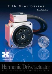
H A - 6 5 5<br />
Total Motion Control<br />
<strong>Harmonic</strong> <strong>Drive</strong> servo<br />
P r e c i s i o n G e a r i n g a n d M o t i o n C o n t r o l
WARNING<br />
<br />
SAFETY GUIDE<br />
For actuators, motors, control units and drivers<br />
manufactured by <strong>Harmonic</strong> <strong>Drive</strong> <strong>LLC</strong><br />
Read this manual thoroughly before designing the application, installation, maintenance or inspection of the actuator.<br />
Indicates a potentially hazardous situation,<br />
which, if not avoided, could result in death<br />
or serious personal injury.<br />
CAUTION<br />
Indicates a potentially hazardous situation, which, if<br />
not avoided, may result in minor or <strong>mode</strong>rate personal<br />
injury and/or damage to the equipment.<br />
LIMITATION OF APPLICATIONS:<br />
The equipment listed in this document may not be used for the applications listed below:<br />
¬ Space equipment ¬ Automobile, automotive parts<br />
¬ Aircraft, aeronautic equipment ¬ Amusement equipment, sport equipment, game machines<br />
¬ Nuclear equipment ¬ Machine or devices acting directly on the human body<br />
¬ Household apparatus ¬ Instruments or devices to transport or carry people<br />
¬ Vacuum equipment ¬ Apparatus or devices used in special environments<br />
If the above list includes your intending application for our products, please consult us.<br />
Safety measures are essential to prevent accidents resulting in death, injury or damage of the equipment due to<br />
malfunction or faulty operation.<br />
CAUTIONS FOR ACTUATORS AT APPLICATION DESIGNING<br />
Always use under followings conditions:<br />
-Ambient temperature: 0 to 40<br />
-Ambient humidity: 20% to 80%RH (Non-condensation)<br />
-Vibration: Max 24.5 m/S 2<br />
CAUTION -No contamination by water, oil<br />
CAUTION<br />
-No corrosive or explosive gas<br />
Follow exactly the instructions in the relating<br />
manuals to install the actuator in the equipment.<br />
-Ensure exact alignment of motor shaft center and<br />
corresponding center in the application.<br />
Failure to observe this caution may lead to vibration,<br />
resulting in damage of output elements.<br />
CAUTION FOR ACTUATORS IN OPERATIONS<br />
Keep limited torques of the actuator.<br />
-Keep limited torques of the actuator.<br />
-Be aware, that if arms attached to output element hits<br />
by accident an solid, the output element may be<br />
CAUTION uncontrollable.<br />
CAUTION<br />
Do not apply impacts and shocks<br />
-Do not use a hammer during installation<br />
-Failure to observe this caution could damage the<br />
encoder and may cause uncontrollable operation.<br />
CAUTION<br />
CAUTION<br />
Never connect cables directly to a power supply<br />
socket.<br />
-Each actuator must be operated with a proper driver.<br />
-Failure to observe this caution may lead to injury, fire or<br />
damage of the actuator.<br />
Avoid handling of actuators by cables.<br />
-Failure to observe this caution may damage the wiring,<br />
causing uncontrollable or faulty operation.<br />
CAUTIONS FOR DRIVERS AT APPLICATION DESIGNING<br />
Always use drivers under followings conditions:<br />
-Mount in a vertical <strong>position</strong> keeping sufficient distance<br />
to other devices to let heat generated by the driver<br />
radiate freely.<br />
-Ambient temperature: 0 to 50<br />
CAUTION<br />
-Ambient humidity: less than 95% RH (Non<br />
CAUTION<br />
condensation)<br />
-No contamination by water, oil or foreign matters<br />
-No corrosive, inflammable or explosive gas<br />
Pay attention to negative torque by inverse load.<br />
–Inverse load may cause damages of drivers.<br />
-Please consult our sales office, if you intent to apply<br />
CAUTION products for inverse load.<br />
CAUTION<br />
CAUTION FOR DRIVERS IN OPERATIONS<br />
Never change wiring while power is active.<br />
-Make sure of power non-active before servicing the<br />
products.<br />
-Failure to observe this caution may result in electric<br />
WARNING shock or personal injury.<br />
CAUTION<br />
Do not make a voltage resistance test.<br />
-Failure to observe this caution may result in damage of<br />
the control unit.<br />
-Please consult our sales office, if you intent to make a<br />
voltage resistance test.<br />
WARNING<br />
CAUTION<br />
Use sufficient noise suppressing means and safe<br />
grounding.<br />
-Keep signal and power leads separated.<br />
-Keep leads as short as possible.<br />
-Ground actuator and driver at one single point, minimum<br />
ground resistance class: D (less than 100 ohms)<br />
-Do not use a power line filter in the motor circuit.<br />
Use a fast-response type ground-fault detector<br />
designed for PWM inverters.<br />
-Do not use a time-delay -type ground-fault detector.<br />
Do not touch terminals or inspect products at least<br />
5 minutes after turning OFF power.<br />
-Otherwise residual electric charges may result in<br />
electric shock.<br />
-Make installation of products not easy to touch their<br />
inner electric components.<br />
Do not operate control units by means of power<br />
ON/OFF switching.<br />
-Start/stop operation should be performed via input<br />
signals.<br />
Failure to observe this caution may result in deterioration<br />
of electronic parts.<br />
DISPOSAL OF AN ACTUATOR, A MOTOR, A CONTROL UNIT AND/OR THEIR PARTS<br />
CAUTION<br />
All products or parts have to be disposed of as industrial waste.<br />
-Since the case or the box of drivers have a material indication, classify parts and dispose them separately.<br />
1
HA655 series servo driver manual<br />
Contents<br />
Chapter 1<br />
Outlines of the HA-655 driver <br />
1<br />
1-1 Main features <br />
1<br />
1-2 Ordering information <br />
2<br />
1-3 Combinations with actuators <br />
2<br />
1-4 Specifications of HA-655 drivers <br />
3<br />
1-5 External drawing of the HA-655drivers <br />
4<br />
1-6 Front panel <br />
5<br />
1-7 Outlines of I/O ports <br />
6<br />
1-8 Operating display panel <br />
8<br />
1-8-1 Outlines of operation <strong>mode</strong>s <br />
8<br />
1-8-2 Selecting a <strong>mode</strong><br />
8<br />
1-8-3 Functions in <strong>mode</strong>s <br />
9<br />
1-9 Outlines of protective functions <br />
10<br />
Chapter 2<br />
1-9-1 Alarms <br />
10<br />
1-9-2 Protective functions <br />
11<br />
Functions <br />
13<br />
2-1 Control system of the HA-655 driver <br />
13<br />
2-2 Position <strong>mode</strong> <br />
14<br />
2-2-1 Command configuration in <strong>position</strong> <strong>mode</strong> <br />
14<br />
2-2-2 Command transmitting system<br />
16<br />
2-2-3 Outputting encoder signal<br />
16<br />
2-2-4 Absolute encoder signals <br />
17<br />
2-2-5 Tuning servo gains <br />
24<br />
2-2-6 FWD inhibit and REV inhibit <br />
26<br />
2-2-7 In-<strong>position</strong> <br />
26<br />
2-3 Speed <strong>mode</strong><br />
27<br />
2-3-1 Speed conversion factor <br />
27<br />
2-3-2 Voltage of <strong>speed</strong> command <br />
27<br />
2-3-3 Tuning servo gains <br />
28<br />
2-3-4 Command change <br />
29<br />
2-3-5 Acceleration / deceleration time constants <br />
29<br />
2-3-6 Zero clamp<br />
29<br />
2-4 Other functions <br />
30<br />
2-4-1 Indication of pulse counts <br />
30<br />
2-4-2 Manual JOG operation <br />
30<br />
2-4-3 Monitoring inputs and operating outputs <br />
30<br />
- Contents 1 -
HA655 series servo driver manual<br />
Chapter 3<br />
I/O ports <br />
31<br />
3-1 Position <strong>mode</strong> <br />
31<br />
3-1-1 I/O port layout <br />
31<br />
3-1-2 Models of I/O port connector CN2 <br />
32<br />
3-1-3 I/O port connections in the <strong>position</strong> <strong>mode</strong> <br />
33<br />
3-1-4 I/O port functions in the <strong>position</strong> <strong>mode</strong> <br />
34<br />
3-1-5 Connection examples in the <strong>position</strong> <strong>mode</strong> <br />
41<br />
3-2 Speed <strong>mode</strong><br />
45<br />
Chapter 4<br />
3-2-1 I/O port layout <br />
45<br />
3-2-2 Models of I/O port connector CN2 <br />
46<br />
3-2-3 I/O port connections in the <strong>speed</strong> <strong>mode</strong> <br />
47<br />
3-2-4 I/O port functions in the <strong>speed</strong> <strong>mode</strong><br />
48<br />
3-2-5 Connection examples in the <strong>speed</strong> <strong>mode</strong><br />
55<br />
Installing the HA-655 driver <br />
57<br />
4-1 Receiving Inspection <br />
57<br />
4-2 Notices on handling<br />
58<br />
4-3 Location and installation <br />
59<br />
4-3-1 Environment of location <br />
59<br />
4-3-2 Notices on installation<br />
59<br />
4-3-3 Installing <br />
60<br />
4-4 Suppressing noise<br />
60<br />
4-4-1 Devices for grounding<br />
60<br />
4-4-2 Installing noise filters <br />
61<br />
4-4-3 Instructions for cabling <br />
62<br />
4-5 Connecting power cables <br />
63<br />
4-5-1 Instructions for power supply <br />
63<br />
4-5-2 Power cable and ground cable<br />
63<br />
4-5-3 Connecting power cables <br />
64<br />
4-5-4 Isolation transformer <br />
64<br />
4-5-5 Protecting power lines<br />
65<br />
4-6 Connecting a ground wire<br />
65<br />
4-7 Connecting motor and regeneration resistor cables <br />
65<br />
4-8 Connecting cables for the encoder and the I/O <br />
66<br />
4-8-1 Preparing the encoder cable and the I/O cable <br />
66<br />
4-8-2 Pin layouts of encoder connector (CN1) <br />
66<br />
4-8-3 Pin layouts of the I/O signal connector (CN2)<br />
67<br />
4-8-4 Connecting cables for the encoder and I/O signals <br />
67<br />
4-9 Power ON and OFF sequences <br />
68<br />
- Contents 2 -
HA655 series servo driver manual<br />
Chapter 5<br />
Operations <br />
70<br />
5-1 Test run<br />
70<br />
5-1-1 Driving an actuator without load<br />
70<br />
5-1-2 Setting parameters <br />
74<br />
5-1-3 Tuning servo parameters <br />
76<br />
5-1-4 End of test run <br />
77<br />
5-2 Usual operation <br />
78<br />
Chapter 6<br />
5-2-1 Notices for daily operations <br />
78<br />
5-2-2 Daily maintenance<br />
78<br />
Operation of the display panel <br />
79<br />
6-1 Summary of <strong>mode</strong>s <br />
79<br />
6-2 Selecting a <strong>mode</strong><br />
79<br />
6-3 Functions of <strong>mode</strong>s <br />
80<br />
6-4 Monitor <strong>mode</strong><br />
81<br />
6-4-1 Operating in the monitor <strong>mode</strong><br />
81<br />
6-4-2 Functions of the monitor <strong>mode</strong><br />
82<br />
6-5 Tune <strong>mode</strong> <br />
92<br />
6-5-1 Operating in the tune <strong>mode</strong> <br />
92<br />
6-5-2 Functions of the tune <strong>mode</strong> <br />
94<br />
6-6 Parameter <strong>mode</strong> <br />
102<br />
6-6-1 Operating in the parameter <strong>mode</strong> <br />
102<br />
6-6-2 Functions of the parameter <strong>mode</strong> <br />
104<br />
6-7 Test <strong>mode</strong> <br />
113<br />
6-7-1 Operating in the test <strong>mode</strong> <br />
113<br />
6-7-2 Functions of the test <strong>mode</strong> <br />
115<br />
6-8 Defaults of parameters <br />
121<br />
Chapter 7<br />
Troubleshooting <br />
122<br />
7-1 Alarms and diagnostic tips <br />
122<br />
7-2 Troubleshooting for improper actuator motions <br />
133<br />
Chapter 8<br />
Index<br />
7-2-1 Improper motions in <strong>position</strong> <strong>mode</strong> <br />
133<br />
7-2-2 Improper motions in <strong>speed</strong> <strong>mode</strong> <br />
137<br />
Options <br />
141<br />
8-1 Extension cables <br />
141<br />
8-2 Connectors<br />
141<br />
8-3 Software for setting up parameters <br />
142<br />
8-4 Backup battery for absolute encoders <br />
142<br />
8-5 Isolation transformer <br />
143<br />
<br />
Index 1<br />
- Contents 3 -
1-2Ordering information<br />
u<br />
HA-655 driver:<br />
HA-655-2A-200<br />
Chapter 1Outlines of the HA-655 driver<br />
AC servo driver HA series<br />
655 series<br />
Nominal current<br />
2 2.4A<br />
4 4.0A<br />
Encoder<br />
No code Incremental encoder<br />
A Absolute encoder<br />
Input voltage<br />
200 200V<br />
u<br />
Extension cables (optional):<br />
for a motor:<br />
EWC - MB * * -M08 - TN<br />
for an incremental encoder: EWC - E * * -B04 - 3M14<br />
for an absolute encoder: EWC - S * * -B08 - 3M14<br />
u Connectors (optional): CNK-HA65-S1<br />
u Software for setting up parameters (optional): PSF-650<br />
u<br />
u<br />
Backup battery for absolute encoder (optional): HAB-ER17/33<br />
Isolation transformer (optional):<br />
PT1 - 200 04 - 200<br />
Cable length 03 3m<br />
05 5m<br />
10 10m<br />
Ins. transformer: PT1 series<br />
2nd volt.<br />
2nd cur.<br />
200 AC 200V<br />
04 4A<br />
08 8A<br />
Prim. Volt. 100 AC100V<br />
115 AC115V<br />
200 AC200V<br />
220 AC220V<br />
1-3Combinations with actuators<br />
Two HA-655 <strong>mode</strong>ls are available for use with FHA-C actuators dealing with their nominal current.<br />
The correct combinations are as follows:<br />
<strong>Drive</strong>r <strong>mode</strong>l<br />
Actuator <strong>mode</strong>l<br />
HA-655-2-200<br />
FHA -17C<br />
FHA -25C<br />
HA-655-4-200<br />
FHA-32C<br />
FHA -40C<br />
Note: Above combinations are valid for 200V power supply only.<br />
- 2 -
Chapter 1Outlines of the HA-655 driver<br />
1-4Specifications of HA-655 drivers<br />
Model<br />
Item HA-655-2-200 HA-655-4-200<br />
Applicable actuator FHA -17C / FHA -25C FHA -32C / FHA -40C<br />
<strong>Drive</strong>r’s nominal current 2.4 A 4.0 A<br />
<strong>Drive</strong>r’s maximum current 7.3 A 18.0 A<br />
Power voltage Main circuit AC200 to 240V(1 / 3-phase) 10 to 15% 50/60Hz<br />
Control circuit AC 100 to 115V(1-phase) or AC200 to 240V(1-phase) 10 to 15% 50/60Hz<br />
Power Control Method<br />
Sinusoidal PWM control<br />
Allowed Environment<br />
Operating temperature: 0 to 50Storage temperature:-20 to 85<br />
Operating/storage humidity: below 95%RH (No condensation)<br />
Vibration resistance: 4.9 m/s 2 10 to 55Hz Impact resistance: 98m/s 2<br />
Ventilation<br />
Self cooling<br />
Installation<br />
Base mount (Wall mount)<br />
Applicable feedback encoder<br />
Incremental or absolute encoder<br />
Encoder interface<br />
Serial transmissionline driver input type<br />
Control <strong>mode</strong><br />
Position <strong>mode</strong>, <strong>speed</strong> <strong>mode</strong><br />
Command voltage<br />
DC10V / maximum <strong>speed</strong><br />
Input impedance: approx. 68kΩ<br />
Input signal<br />
Servo-ON, Alarm clear, FWD-enable, REV-enable, Command alternation,<br />
*Absolute date request, *Absolute multi-turn data clear (Insulated by opt-isolators)<br />
Output signal<br />
Attained <strong>speed</strong>, Alarm, Alarm code (4-bit)<br />
(Insulated by opt-isolators)<br />
Speed control range<br />
1:1000 or more<br />
Speed regulation By load Below 0.05% at nominal <strong>speed</strong><br />
by load change from zero to maximum torque<br />
By voltage Below 0.05% at nominal <strong>speed</strong><br />
by voltage change in its allowance<br />
By temperature Below 0.2% at nominal <strong>speed</strong><br />
by temperature change from 0 to 50<br />
Command pulse interface Line driver(compliant with EIA422A standard), open collector<br />
Command configuration<br />
1-pulse train (step and direction), 2-pulse train (FWD/REV pulses),<br />
2-phase pulse (A-B phase pulses with 90 degree difference)<br />
Command frequency Line driver: 500kpps(max)<br />
Open collector: 200kpps(max) , limited by actuator’s maximum <strong>speed</strong><br />
Input signal<br />
Servo-ON, Error counteralarm clear, FWD inhibit, REV inhibit,<br />
*Absolute date request, *Absolute multi-turn data clear (Insulated by opt-isolators)<br />
Output signal<br />
In-<strong>position</strong>, alarm, ready, alarm code (4-bit)<br />
(Insulated by opt-isolators)<br />
Position signal output<br />
Phase-A, -B, -Z; line driver output;<br />
Phase-Z: Photo-coupler output<br />
Analog monitor<br />
2ch:motor <strong>speed</strong>, current command<br />
Configuration<br />
Display: 7-segment LED 6 digits (red)<br />
Operation key: keys<br />
Monitor function Motor <strong>speed</strong> (r/min), torque (%), over load rate (%)<br />
Input signal monitor, output signal monitor, alarm history (up to 8 alarms )<br />
Parameters System parameters Tune parameters<br />
Protection function<br />
Over current, overload, error counter overflow, over <strong>speed</strong>, abnormal regeneration,<br />
Encoder failure, communication error, CPU failure, memory failure,<br />
*multi-turn data error, *encoder system failure, *encoder overflow, *battery low<br />
voltage, *absolute data transmitting rule error<br />
Regeneration Built-in regeneration resistor: absorbable power: 40W (maximum)<br />
External regeneration resistor is acceptable.<br />
Functions<br />
Monitoring, self diagnosis, electronic gear, JOG operation, trapezoidal <strong>speed</strong><br />
profile, and etc. *backup battery for multi-turn data<br />
Rush current suppressing circuit Built-in<br />
Operation <strong>mode</strong> Monitor <strong>mode</strong> (usual operations), test <strong>mode</strong>, tune <strong>mode</strong>,<br />
Parameter <strong>mode</strong><br />
Mass 1.5 kg 1.7 kg<br />
Note: the specifications marked with (*) are valid for absolute encoders only.<br />
Speed <strong>mode</strong><br />
Position <strong>mode</strong><br />
Front panel<br />
- 3 -
Chapter 1Outlines of the HA-655 driver<br />
1-5External drawing of the HA-655 drivers<br />
The external drawing is shown as follows:<br />
<br />
Unitmm(Third angle projection method)<br />
Heat sink<br />
Ventilation holes<br />
Dimensions for mounting<br />
Label<br />
Terminal cover<br />
Note 1: When HA-655 drivers are installed in a cabinet, leave enough ventilation space for cooling as<br />
shown below.<br />
- 4 -
Chapter 1Outlines of the HA-655 driver<br />
1-6Front panel<br />
DOWN key<br />
UP key<br />
LED display<br />
ADJ key<br />
SET key<br />
Power supply terminal<br />
For control power: r,s<br />
For main power: R,S,T<br />
HA-655-2<br />
CN3 serial port connector<br />
(compliant with RS-232C)<br />
CN2: I/O connector<br />
For regeneration resistor: R1,R2<br />
For actuator: U,V,W<br />
Ground terminals<br />
CN1: Encoder connector<br />
Functions<br />
LED display<br />
Indicates operating states of the HA-655 driver, parameters, alarms, by a 6-digit 7segment-LED.<br />
Keys labeled [UP], [DOWN], [ADJ], and [SET]<br />
Are used for changing indications, setting and tuning functional parameters, and operating an actuator<br />
manually in a JOG <strong>mode</strong>.<br />
CN1: encoder connector<br />
Accepts a connector of an encoder cable form an actuator.<br />
CN2: I/O connector<br />
Accepts I/O signals to/from a host device.<br />
CN3: Serial port connector (compliant with RS-232C)<br />
Is connected to a PC with a dedicated cable. You can monitor, set, and tune parameters on the PC’s<br />
display. (Notice: Optional software is available.)<br />
Power supply terminals: r, s, R, S, T<br />
Are provided for connecting the power supply. Control power is supplied to the [r, s] terminals, and main<br />
power is supplied to the [R,S,T] terminals. (single Phase: R,S; or three phase: R,S,T).<br />
External regeneration resistor terminals: R1, R2<br />
If the built-in regeneration resistor is insufficient in its capacity to handle frequent start/stop operations of<br />
an actuator, an external resistor can be connected to these terminals.<br />
Actuator terminals: U, V, W<br />
Accept an actuator cable. Connect each motor wire to the driver’s terminal marked with a same symbol.<br />
If you confuse the symbols, the driver and the actuator may be in failure.<br />
Ground terminals (Protective earth)<br />
Connect grounds here to prevent electrical shock.<br />
- 5 -
Chapter 1Outlines of the HA-655 driver<br />
1-7Outlines of I/O ports<br />
The CN2 connector provides input and output signals to and from a host device. The 50 pins of the<br />
connector are assigned to the following signals in each of the [<strong>position</strong> <strong>mode</strong>] and the [<strong>speed</strong> <strong>mode</strong>].<br />
(Notice: Do not connect signals to pins marked “-“.)<br />
<br />
Position <strong>mode</strong><br />
Speed <strong>mode</strong><br />
Pin Signal Symbol I/O Pin Signal Symbol I/O<br />
Input signal common IN-COM Input Input signal common IN-COM Input<br />
Clear CLEAR Input Clear CLEAR Input<br />
Servo-ON S-ON Input Servo-ON S-ON Input<br />
FWD inhibit FWD-IH Input FWD enable FWD-EN Input<br />
REV inhibit REV- IH Input REV enable REV-EN Input<br />
Command change CMD-CHG Input<br />
<br />
Input signal common IN-COM Input Input signal common IN-COM Input<br />
<br />
<br />
<br />
<br />
<br />
<br />
<br />
<br />
<br />
<br />
<br />
<br />
<br />
<br />
Speed monitor SPD-MON Output Speed monitor SPD-MON Output<br />
Current monitor CUR-MON Output Current monitor CUR-MON Output<br />
Monitor ground GND Output Monitor ground GND Output<br />
+24V +24V Input <br />
FWD pulse FWD+ Input <br />
FWD pulse FWD- Input <br />
REV pulse REV+ Input <br />
REV pulse REV- Input <br />
Speed command SPD-CMD Input<br />
Speed command ground SG-GND Input<br />
In-<strong>position</strong> IN-POS Output Attained <strong>speed</strong> HI-SPD Output<br />
Alarm ALARM Output Alarm ALARM Output<br />
<br />
<br />
Ready READY Output Ready READY Output<br />
Alarm-A+ ALM-A Output Alarm-A ALM-A Output<br />
Alarm-B ALM-B Output Alarm-B ALM-B Output<br />
Alarm-C ALM-C Output Alarm-C ALM-C Output<br />
Alarm-D ALM-D Output Alarm-D ALM-D Output<br />
Phase-Z (OC) Z Output Phase-Z (OC) Z Output<br />
Output common OUT-COM Output Output common OUT-COM Output<br />
Phase-A(LD) A+ Output Phase-A(LD) A+ Output<br />
Phase-A(LD) A- Output Phase-A(LD) A- Output<br />
Phase-B(LD) B+ Output Phase-B(LD) B+ Output<br />
Phase-B(LD) B- Output Phase-B(LD) B- Output<br />
Phase-Z(LD) Z+ Output Phase-Z(LD) Z+ Output<br />
Phase-Z(LD) Z- Output Phase-Z(LD) Z- Output<br />
Frame ground FG Output Frame ground FG Output<br />
Note: OC: open collector port, LD: line driver port<br />
- 6 -
Chapter 1Outlines of the HA-655 driver<br />
<br />
Position <strong>mode</strong><br />
Speed <strong>mode</strong><br />
Pin Signal Symbol I/O Pin Signal Symbol I/O<br />
Input signal common IN-COM Input Input signal common INPUT-COM Input<br />
Clear CLEAR Input Clear CLEAR Input<br />
Servo-ON S-ON Input Servo-ON S-ON Input<br />
FWD inhibit FWD-IH Input FWD enable FWD-EN Input<br />
REV inhibit REV- IH Input REV enable REV-EN Input<br />
Command change CMD-CHG Input<br />
<br />
Input signal common IN-COM Input Input signal common IN-COM Input<br />
<br />
Absolute data request ABS-REQ Input Absolute data request ABS-REQ Input<br />
Abs(multi-turn)data clear ABS-CLEAR Input Abs(multi-turn)data clear ABS-CLEAR Input<br />
<br />
<br />
<br />
<br />
<br />
<br />
<br />
<br />
<br />
<br />
<br />
Speed monitor SPD-MON Output Speed monitor SPD-MON Output<br />
Current monitor CUR-MON Output Current monitor CUR-MON Output<br />
Monitor ground GND Output Monitor ground GND Output<br />
+24V +24V Input <br />
FWD pulse FWD+ Input <br />
FWD pulse FWD- Input <br />
REV pulse REV+ Input <br />
REV pulse REV- Input <br />
Speed command SPD-CMD Input<br />
Speed command ground SG-GND Input<br />
In-<strong>position</strong> IN-POS Output Attained <strong>speed</strong> HI-SPD Output<br />
Alarm ALARM Output Alarm ALARM Output<br />
<br />
<br />
Ready READY Output Ready READY Output<br />
Alarm-A+ ALM-A Output Alarm-A ALM-A Output<br />
Alarm-B ALM-B Output Alarm-B ALM-B Output<br />
Alarm-C ALM-C Output Alarm-C ALM-C Output<br />
Alarm-D ALM-D Output Alarm-D ALM-D Output<br />
Phase-Z (OC) Z Output Phase-Z (OC) Z Output<br />
Output common OUT-COM Output Output common OUT-COM Output<br />
Phase-A(LD) A+ Output Phase-A(LD) A+ Output<br />
Phase-A(LD) A- Output Phase-A(LD) A- Output<br />
Phase-B(LD) B+ Output Phase-B(LD) B+ Output<br />
Phase-B(LD) B- Output Phase-B(LD) B- Output<br />
Phase-Z(LD) Z+ Output Phase-Z(LD) Z+ Output<br />
Phase-Z(LD) Z- Output Phase-Z(LD) Z- Output<br />
Frame ground FG Output Frame ground FG Output<br />
Note: OC: open collector port, LD: line driver port<br />
- 7 -
Chapter 1Outlines of the HA-655 driver<br />
1-8Operating display panel<br />
The HA-655 driver provides a 6-digit LED display and four operation keys on the front panel. The panel<br />
executes monitoring, tuning, setting, and JOG operation.<br />
1-8-1Outlines of operation <strong>mode</strong>s<br />
The HA-655 driver provides the following four <strong>mode</strong>s: monitoring, tuning, setting, and operations.<br />
Monitor <strong>mode</strong><br />
The HA-655 driver displays <strong>position</strong> and <strong>speed</strong> commands, a current <strong>position</strong> from a motor-encoder, a<br />
pulse count in an error counter, states of input and output signals, load conditions, alarm histories, and a<br />
code number for the actuator for which the driver is set. The <strong>mode</strong> can be used for diagnosing an<br />
abnormal driver.<br />
After power supply, the monitor <strong>mode</strong> starts up and works as the hub of other three <strong>mode</strong>s for operation.<br />
Tune <strong>mode</strong><br />
The tuning <strong>mode</strong> includes various parameters to control the actuator motion. Setting the most suitable<br />
value for each parameter obtains the optimum performance of the actuator.<br />
Parameter <strong>mode</strong><br />
The parameter <strong>mode</strong> sets various parameter values relating to the fundamental operational functions<br />
such as: specifications of the <strong>position</strong> <strong>mode</strong> or the <strong>speed</strong> <strong>mode</strong>, configurations of input signals, an<br />
electronic gear function, limiting values of <strong>speed</strong> and torque, and parameters to communicate with a<br />
host.<br />
Test <strong>mode</strong><br />
The test <strong>mode</strong> includes required functions for system tests; such as JOG operation functions, operations<br />
of pseudo output signals, I/O signal monitors, and so on.<br />
1-8-2 Selecting a <strong>mode</strong><br />
After powering the driver, the monitor <strong>mode</strong> starts up automatically. The [ADJ] and [SET] keys select a<br />
<strong>mode</strong>.<br />
Powering<br />
Monitor <strong>mode</strong><br />
ADJ<br />
ADJ SET SET<br />
3 sec. 3 sec.<br />
3 sec.<br />
Tune <strong>mode</strong><br />
Parameter <strong>mode</strong><br />
Test <strong>mode</strong><br />
SET<br />
- 8 -
1-8-3 Functions in <strong>mode</strong>s<br />
Chapter 1Outlines of the HA-655 driver<br />
Each <strong>mode</strong> individually provides the following functions of the <strong>position</strong> <strong>mode</strong> and the <strong>speed</strong> <strong>mode</strong>.<br />
Mode Code Position <strong>mode</strong> Setting Code Speed <strong>mode</strong> Setting<br />
0 Error counter state 0 Error counter state<br />
1 Motor revolutions 1 Motor revolutions<br />
2 2 Speed command voltage<br />
3 Error pulse count (Low) 3 Error pulse count (Low)<br />
4 Error pulse count (High) 4 Error pulse count (High)<br />
5 Torque monitor 5 Torque monitor<br />
6 Overload rate 6 Overload rate<br />
7 Feedback pulse (Low) 7 Feedback pulse (Low)<br />
8 Feedback pulse (High)<br />
Impossible<br />
8 Feedback pulse (High)<br />
Impossible<br />
9 Command pule (Low) 9 <br />
A Command pulse (High) A <br />
b Command pulse frequency b <br />
c I/O monitor c I/O monitor<br />
d Alarm history d Alarm history<br />
E Actuator code E Actuator code<br />
F<br />
<br />
F<br />
<br />
Monitor <strong>mode</strong><br />
Tune <strong>mode</strong><br />
Parameter <strong>mode</strong><br />
Test <strong>mode</strong><br />
0 Speed loop gain 0 Speed loop gain<br />
1 S-loop integral compensation 1 S-loop integral compensation Possible<br />
2 Position loop gain Possible 2 Position loop gain<br />
3 Feed-forward gain 3 <br />
4 In-<strong>position</strong> range<br />
4 <br />
5 5 Attained <strong>speed</strong><br />
6 6 Internal <strong>speed</strong> command<br />
7 7 Acceleration time constant Possible<br />
8 8 Deceleration time constant<br />
9 9 Speed command offset<br />
0 Control <strong>mode</strong> 0 Control <strong>mode</strong> Possible<br />
1 Command configuration 1 <br />
2 Multiplication of 2-phase pulse 2 <br />
3 Electronic gear - denominator Possible 3 <br />
4 Electronic gear - numerator 4 <br />
5 Error count cleared by S-ON 5 <br />
6 Position error allowance<br />
6 <br />
7 7 Zero clamp<br />
8 Rotary direction 8 Rotary direction<br />
9 Speed conversion factor 9 Speed conversion factor<br />
A Speed limit Possible A Speed limit<br />
Possible<br />
b Torque limit b Torque limit<br />
c Alarm logic<br />
c Alarm logic<br />
d d <br />
E E <br />
f ABS multi-turn data clear Impossible f ABS multi-turn data clear Impossible<br />
Jo JOG operation Possible Jo JOG operation Possible<br />
SP JOG <strong>speed</strong><br />
SP JOG <strong>speed</strong><br />
Possible<br />
Ac JOG acceleration<br />
Ac JOG acceleration<br />
Possible<br />
InP Output port operation Possible InP Output port operation Possible<br />
c I/O monitor Impossible c I/O monitor Impossible<br />
An Analog monitor manual output Possible An Analog monitor manual output Possible<br />
So Speed command auto-offset Possible So Speed command auto-offset Possible<br />
- 9 -
Chapter 1Outlines of the HA-655 driver<br />
1-9Outlines of protective functions<br />
1-9-1Alarms<br />
HA-655 drivers provide various functions to protect actuators and drivers from the occurrence of<br />
abnormalities. When a function detect faults, the actuator enters a free rotation state, a two-digit alarm<br />
code is indicated on the display, and a set of 4-bit alarm signals is transmitted to the host.<br />
Alarm<br />
4-bit ALM ALM ALM ALM<br />
Alarm description<br />
code<br />
code -D -C -B -A<br />
Releasing<br />
10 Over <strong>speed</strong> 1011 ON OFF ON ON Impossible<br />
20 Over load 0001 OFF OFF OFF ON Possible<br />
21 Overheat 1000 ON OFF OFF OFF Impossible<br />
30 Over current 1001 ON OFF OFF ON Impossible<br />
41 Abnormal regeneration 1010 ON OFF ON OFF Impossible<br />
50 Encoder failure 1101 ON ON OFF ON Impossible<br />
51 Abnormal encoder signal 1101 ON ON OFF ON Impossible<br />
52 UVW failure 1101 ON ON OFF ON Impossible<br />
53 *ABS system failure 1101 ON ON OFF ON Impossible<br />
54 *ABS MTD over flow 1101 ON ON OFF ON Impossible<br />
55 *ABS multi-turn data error 1101 ON ON OFF ON Impossible<br />
56 *ABS low battery voltage 1101 ON ON OFF ON Impossible<br />
57 *ABS send data rule error 1101 ON ON OFF ON Impossible<br />
60 Error counter overflow 0010 OFF OFF ON OFF Possible<br />
70 Memory failure (RAM) 0101 OFF ON OFF ON Impossible<br />
71 Memory failure (EEPROM) 0101 OFF ON OFF ON Impossible<br />
76 CPU failure 0100 OFF ON OFF OFF Impossible<br />
Note: the alarm codes 53 through 57 are valid for absolute encoders only.<br />
- 10 -
Chapter 1Outlines of the HA-655 driver<br />
1-9-2Protective functions<br />
The HA-655 driver provides the following alarms to protect the servo system, and presents an alarm<br />
code on the preceding paragraph.<br />
Over <strong>speed</strong> (10)<br />
If a motor exceeds its maximum <strong>speed</strong> or if motor rotates abnormally, the alarm occurs. To clear the<br />
alarm, shut off the control power once and turn it on again.<br />
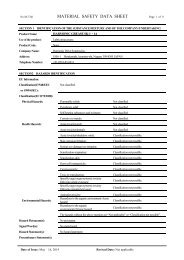
Over load (20)<br />
The driver always monitors the motor current, and if the current exceeds the curve in the figure below,<br />
the overload alarm occurs.<br />
1.2 times of<br />
For example:<br />
nominal current<br />
(1) The alarm occurs if the current<br />
1000<br />
slightly exceeds 1.2 times of<br />
nominal current for a long<br />
duration.<br />
Over load range<br />
(2) The alarm occurs if the current of<br />
three times of the nominal current<br />
flows for 20 seconds.<br />
It is possible to clear the alarm by<br />
inputting signal to [CN2-2 clear:<br />
CLEAR].<br />
Delay (s)<br />
100<br />
10<br />
1 2 3<br />
Nominal<br />
Max. current<br />
current<br />
Actuator current<br />
Overheat (21)<br />
The alarm occurs by activating the thermal switch of an IPM element in the HA-655 driver. To clear the<br />
alarm after troubleshooting, shut off the control power once and turn it on again.<br />
Over current (30)<br />
The alarm occurs when the servo control element of the driver detects excessive current. To clear the<br />
alarm after troubleshooting, shut off the control power once and turn it on again.<br />
Abnormal regeneration (41)<br />
The alarm occurs by activating the thermal switch of the regeneration resistor in the HA-655 driver at<br />
100. To clear the alarm after troubleshooting, shut off the control power once and turn it on again.<br />
Encoder failure (50)<br />
The alarm occurs when the encoder signal ceases. To clear the alarm after troubleshooting, shut off the<br />
control power once and turn it on again.<br />
The alarm also occurs when a built-in battery of the HA-655 driver for the absolute encoder is taken off in<br />
spite of normal conditions. To clear the alarm, shut off the control power once and turn it on again.<br />
- 11 -
Chapter 1Outlines of the HA-655 driver<br />
Abnormal encoder signal (51)<br />
The alarm occurs when the driver has failed to receive two sequential signals. To clear the alarm after<br />
troubleshooting, shut off the control power once and turn it on again.<br />
UVW failure (52)<br />
The alarm occurs when the encoder UVW signals are abnormal. To clear the alarm after troubleshooting,<br />
shut off the control power once and turn it on again.<br />
ABS system failure (53)<br />
For the absolute encoder, the alarm occurs when all power supplies (power supply, built-in condenser,<br />
and battery) for the encoder are failure. For example, it occurs at the first power supply after purchasing,<br />
and at power supply after disconnecting the cable between the driver and the encoder for a long duration.<br />
To recover the alarm, input the multi-turn data clear signal at least 4 seconds, and shut off the control<br />
power once and turn it on again.<br />
ABS MTD overflow (54)<br />
For the absolute encoder, the alarm occurs when the count for multi-turn data (MTD) goes beyond the<br />
range of +4095 to - 4096 turns (motor axis). To recover the alarm, input the multi-turn data clear signal at<br />
least 4 seconds, and shut off the control power once and turn it on again.<br />
ABS multi-turn data error (55)<br />
For the absolute encoder, during an energy-saving <strong>mode</strong>, where no power by power supply but the<br />
encoder circuit is active only by the power of a built-in condenser and a built-in battery, the alarm occurs<br />
when the encoder rotates too fast at the acceleration rate and <strong>speed</strong> exceeding the recording ability of<br />
the multi-turn counter on the <strong>mode</strong>. To recover the alarm, input the multi-turn data clear signal at least 4<br />
seconds, and shut off the control power once and turn it on again.<br />
ABS low battery voltage (56)<br />
For the absolute encoder, when voltage of the built-in battery is low. To recover the alarm, change the<br />
battery for a new one, and shut off the control power once and turn it on again.<br />
ABS send data rule error (57)<br />
The absolute encoder rotates more than 127 resolvable pulses by external torque during transmitting<br />
absolute data. To recover the alarm, shut off the control power once and turn it on again.<br />
Error counter overflow (60)<br />
The alarm occurs when an error count exceeds the set value in [parameter <strong>mode</strong>][6: <strong>position</strong> error<br />
allowance]. It is possible to clear the alarm by inputting a signal to [CN2-2clear: CLEAR]. The error<br />
count is cleared at the same time.<br />
Memory failure (RAM) (70)<br />
The alarm occurs when the driver’s RAM memory fails. It is impossible to clear the alarm.<br />
Memory failure (EEPROM) (71)<br />
The alarm occurs when the driver’s EEROM memory fails. It is impossible to clear the alarm.<br />
CPU failure (76)<br />
The alarm occurs when the driver’s CPU fails. It is impossible to clear the alarm.<br />
- 12 -
Chapter 2Functions<br />
Chapter 2Functions<br />
2-1Control system of the HA-655 driver<br />
It is said that [plan, do, see] is essential to perform perfect<br />
jobs. In other words, the [plan, do, see] is the repeating<br />
Perfect job cycle<br />
cycle of commandactionresult feedbackmodified<br />
command action feedback . Plan Do See<br />
Driving machines precisely requires the same control as<br />
the above job cycle, that is [Motion commandrun<br />
feedbackmodified command].<br />
Feedback<br />
For example, assume the required motion is rotation to a<br />
target angle and stopping there. To perform the motion,<br />
the motor must be equipped with an angular sensor to<br />
detect a current <strong>position</strong>, and the <strong>position</strong> data must be<br />
compared with the command. If the <strong>position</strong> data is<br />
different than the command, the motor rotates until the<br />
<strong>position</strong> data becomes equal to the command. This is an<br />
example of a <strong>position</strong> servo system.<br />
The <strong>speed</strong> control system is the same. The motor is<br />
equipped with a <strong>speed</strong> sensor and the <strong>speed</strong> is compared<br />
with the <strong>speed</strong> command. If the <strong>speed</strong> is different from the<br />
command, the motor accelerates or decelerates until the<br />
motor <strong>speed</strong> becomes equal to the command. This is an<br />
example of the <strong>speed</strong> servo system.<br />
Precise motion control<br />
Com. Run Result<br />
Feedback<br />
The HA -655 driver realizes above both controls of <strong>position</strong> and <strong>speed</strong> with the same unit.<br />
The fundamental configuration of servo system of the HA-655 driver is as follows:<br />
Speed<br />
command<br />
HA-655 driver<br />
<strong>Drive</strong>n machine<br />
Position<br />
command<br />
Position<br />
control block<br />
Speed<br />
control block<br />
Power<br />
amplifier<br />
Actuator<br />
Speed feedback<br />
Position feedback<br />
Encoder<br />
The HA-655 driver function is consists of three parts: the <strong>position</strong> control block, the <strong>speed</strong> control block,<br />
and the power amplifier.<br />
In the <strong>position</strong> <strong>mode</strong>, a command <strong>position</strong> from a host is compared to a feedback <strong>position</strong>. If there is a<br />
difference between them, the <strong>position</strong> control block commands the power amplifier through the <strong>speed</strong><br />
control block to flow current to the actuator until there is no difference.<br />
In the <strong>speed</strong> <strong>mode</strong>, a <strong>speed</strong> command is directly inputted to the <strong>speed</strong> control block. The <strong>speed</strong> block<br />
compares the command and current feedback <strong>speed</strong>. If there is a difference between them, the <strong>speed</strong><br />
control block commands to the power amplifier flow the current to the actuator until there is no<br />
difference.<br />
The HA-655 driver allows two types of encoder as a functional member of the feedback system,<br />
optionally: an incremental encoder or an absolute encoder.<br />
- 13 -
2-2Position <strong>mode</strong><br />
Chapter 2Functions<br />
The HA -655 driver makes use of either the <strong>position</strong> control or the <strong>speed</strong> control. This section describes<br />
the <strong>position</strong> <strong>mode</strong>. ( The default setting is the [<strong>position</strong> <strong>mode</strong>].)<br />
Before driving, set the control <strong>mode</strong> by [parameter <strong>mode</strong>] [0: control <strong>mode</strong>].<br />
2-2-1Command configuration in <strong>position</strong> <strong>mode</strong><br />
In the <strong>position</strong> <strong>mode</strong>, the command is transmitted from a host in the form of a digital pulse signal train.<br />
The HA-655 driver provides two pair of two ports (CN2-27&28, CN2-29&30) for the command pulses.<br />
Signals of three type of configurations are available for the ports.<br />
Setting a command configuration<br />
[Parameter <strong>mode</strong>][1: command configuration]<br />
Relating I/O pins<br />
Input pins: CN2-26 to 30<br />
(1)2-pulse train (FWD and REV pulse train)<br />
Two pairs of two terminals are provided, and each of FWD and REV pulse trains is assigned a pair<br />
independently. FWD commands and REV commands are inputted in the pair of FWD ports and REV<br />
ports respectively, as shown in the figure below. When signals are inputted to a pair of terminals, the<br />
signal to the other should keep [OFF] state.<br />
FWD command<br />
REV command<br />
Opt-isolator: OFF<br />
FWD+<br />
FWD-<br />
<br />
<br />
<br />
<br />
Opt-isolator: OFF<br />
REV+<br />
REV-<br />
<br />
<br />
<br />
<br />
(2)1-pulse train (polarity + pulse train)<br />
One pair of terminals is assigned dedicatedly for command pulse train, and the other is assigned to a<br />
sign for rotary direction. Position commands are inputted in the FWD port pair only and the REV port pair<br />
accepts the sign of rotary direction, as shown in the figure below. [OFF] or [Low level] state is for the<br />
FWD command and [ON] or [High] level is for the REV command.<br />
FWD command<br />
REV command<br />
FWD+<br />
FWD-<br />
<br />
<br />
<br />
<br />
Opt-isolator: OFF<br />
Opt-isolator: ON<br />
REV+<br />
REV-<br />
<br />
<br />
<br />
<br />
- 14 -
Chapter 2Functions<br />
(3)2-phase pulse train (A-B phase pulses with 90 degree difference)<br />
Both port pairs receive the command pulse trains that have a 90 electric degree difference relative to<br />
each other as shown in the figure below. For the FWD command, the pulse train to the FWD ports<br />
advances 90 degrees from the REV port train. For the REV command, the REV port train advances from<br />
the FWD port train.<br />
The encoder pulse trains to the driver have this 2-phase pulse configuration.<br />
FWD command<br />
90<br />
differ<br />
REV command<br />
90<br />
differ<br />
FWD+<br />
FWD-<br />
REV+<br />
REV-<br />
<br />
<br />
<br />
<br />
<br />
<br />
<br />
<br />
Multiplication of command<br />
When the command configuration is a<br />
[2-phase pulse] type, it is possible to multiply<br />
the command pulse train by 2 or 4 for the<br />
command pulse train to an actuator.<br />
The encoder feedback pulse train is<br />
quadrupled.<br />
FWD<br />
REV<br />
Input<br />
1<br />
2 3 4<br />
Setting<br />
Double<br />
1<br />
2 3 4 5 6 7 8<br />
[Parameter <strong>mode</strong>] [2: multiplication of<br />
2-phase pulse]<br />
Quadruplicated<br />
1<br />
2 3 4 5 6 7 8 9 10 11 12 13 14 15 16<br />
Electronic gear<br />
The electronic gear function can be set make a given<br />
displacement of the driven mechanism for one<br />
command pulse, an integer, or a convenient number.<br />
For example, it is convenient to set the displacement of<br />
0.1 micrometer for one pulse as shown in figure to the<br />
right.<br />
The function multiples the command pulse count by the<br />
coefficient (fraction).<br />
The relation of [denominator / numerator] of the coefficient<br />
is obtained as follows:<br />
Rotary motion:<br />
1 P<br />
FHA<br />
-C<br />
0.1m<br />
W<br />
Electronic gear - denominator<br />
Electronicgear - numerator<br />
Angle per pulse<br />
=<br />
× Actuator resolution×<br />
Reductionratio of load<br />
4<br />
360<br />
Linear motion:<br />
Electronic gear - denominator<br />
Electronic gear - numerator<br />
Displacementperpulse<br />
=<br />
× Actuator resolution×<br />
4<br />
Feedpitch of driven mechanism<br />
With above formulas, each denominator and numerator should be set an integer between 1 and 50.<br />
Setting<br />
[Parameter <strong>mode</strong>][3: electronic gear -denominator], and [4:electronic gear-numerator]<br />
- 15 -
Chapter 2Functions<br />
2-2-2 Command transmitting system<br />
Two systems are provided for transmitting command pulses: [open collector] and [line driver].<br />
Open collector system<br />
This system employs a transistor whose emitter is<br />
common and whose collector is open. Since the<br />
output signal is voltage type, this system is<br />
unsuitable for long distance transmission due to line<br />
voltage drop.<br />
Collector<br />
Emitter<br />
Output<br />
Transmission<br />
line<br />
Use twist<br />
pair cable.<br />
Input<br />
Line driver system<br />
The line driver system conforms to (EIA) RS-422<br />
standard providing line drivers for transmitting<br />
signal pulses. Since the output signal is current type,<br />
this system is suitable for long distance<br />
transmissions without attenuation of signals.<br />
Line driver<br />
Transmission<br />
line<br />
Furthermore, the line driver system transmits data<br />
faster than the open collector system.<br />
Output<br />
Use twist<br />
pair cable.<br />
Input<br />
2-2-3 Outputting encoder signals<br />
Two kinds of encoder are selectable for the FHA-C<br />
series actuator: incremental or absolute. The<br />
incremental encoder feeds back two pulse-trains<br />
into the HA-655 driver as shown in the figure to the<br />
right. The pulse trains are called [phase-A] and<br />
[phase-B]. For the encoder resolution, refer to<br />
actuator’s technical manual.<br />
Phase-A<br />
Phase-B<br />
Phase-Z<br />
On the other hand, the absolute encoder feeds back<br />
a combination of absolute signals and two<br />
pulse-train signals.<br />
In addition to the 2-phase pulse trains, both<br />
encoders output a [phase-Z] pulse signal once per<br />
motor rotation for use as an origin. The pulse signal<br />
is sometimes called [phase-C] or [index].<br />
The HA-655 driver outputs encoder signals using a<br />
line driver system. The signals can be received by a<br />
line receiver: AM26LS32 (EIA -422A) or equivalent.<br />
Phase-Z signal is also available (open collector<br />
output {CN-42 pin}).<br />
Phase-A<br />
Phase-B<br />
Phase-Z<br />
Forward<br />
Reverse<br />
The phase-Z signal is asynchronous.<br />
Three encoder signals mentioned above are<br />
available for a host.<br />
Relating I/O pins<br />
Output pins: CN2-42 to 49<br />
- 16 -
Chapter 2Functions<br />
2-2-4 Absolute encoder signals<br />
u<br />
General descriptions and functions of absolute encoders<br />
The absolute encoder housed in a FHA-C series actuator provides an absolute sensor to generate an<br />
absolute pulse train for a resolvable <strong>position</strong> (the sensor is herein after referred to as “single-turn<br />
encoder”.), and an electronic counter to generate an absolute pulse train for a revolution of the motor<br />
(the counter is hereinafter referred to as “multi-turn counter”.).<br />
An absolute <strong>position</strong> of the encoder is kept in the memory, which is always energized by a combination<br />
of the built-in condenser in the actuator and the backup battery housed in the HA-655 driver.<br />
Please interpret that “single-turn” and “multi-turn” in the manual mean one and plural revolutions of the<br />
encoder (the motor) in an actuator, respectively. Therefore, the actual actuator resolvable <strong>position</strong> of<br />
either “single-turn” or “multi-turn” can be obtained by multiplying an absolute pulse train of the single-turn<br />
encoder and the multi-turn counter by a reduction ratio of the actuator.<br />
u<br />
Single-turn absolute encoder<br />
The single-turn encoder is composed of an encoder disk, an LED light source, and a photo-detector. The<br />
single-turn absolute encoder system outputs a current absolute pulse train combined with an absolute<br />
pulse train of the multi-turn counter in response to the [ABS data request] signal. The resolution of the<br />
encoder is 8192 <strong>position</strong>s per turn (13 bits). To obtain actual resolvable <strong>position</strong> of the actuator, the<br />
absolute pulse train should be multiplied by the reduction ratio of the actuator.<br />
u<br />
Multi-turn counter<br />
The multi-turn counter outputs a current absolute pulse train combined with an absolute pulse train of<br />
the single-turn absolute encoder system in response to the [ABS data request] signal. The allowed<br />
range of the counter is from +4095 to –4096. To obtain an actual resolvable <strong>position</strong> of the actuator, the<br />
absolute pulse train should be multiplied by the reduction ratio of the actuator.<br />
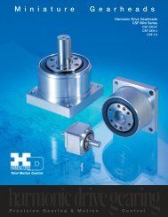
u Energy-saving <strong>mode</strong><br />
In the energy-saving <strong>mode</strong>, even during no power supply for the HA-655 driver, the multi-turn counter<br />
keeps a count in its memory only by the power of a built-in condenser and a built-in battery.<br />
u<br />
Allowable encoder (motor) <strong>speed</strong> in energy-saving <strong>mode</strong><br />
The limit of an encoder (a motor) <strong>speed</strong> is 5,000r/min. The [alarm 55: ABS multi-turn data error] occurs if<br />
the encoder rotates at more than the limited <strong>speed</strong>, and a correct absolute pulse train of the multi-turn<br />
counter may not obtained. Moreover, there are additional limits during motor acceleration duration as<br />
shown the figure below.<br />
Error undetectable range<br />
(abnormal data)<br />
Error detectable range (abnormal data)<br />
Encoder <strong>speed</strong>(r/min)<br />
Allowable <strong>speed</strong> range<br />
16000rad/s 2<br />
5000rad/s 2<br />
- 17 -<br />
Response<br />
(ms)<br />
time
Chapter 2Functions<br />
u<br />
Notice at power on<br />
If power is turned on while the motor rotates at 2800r/min or more, the [Alarm 55] may occur. In spite of<br />
the alarm, the multi-turn counter works normal.<br />
u<br />
ABS (multi -turn) data clear signal (CN2-11: ABS-CLEAR)<br />
The ABS (multi-turn) data clear signal should be inputted at:<br />
(a) the initial power supply, and;<br />
(b) wasting about 30 minutes or more for exchanging the built-in battery.<br />
At either case, the multi-turn counter does not keep any data. To recover from the problem, move the<br />
actuator to a proper origin and input the [ABS (multi-turn) data clear signal] at least four seconds to clear<br />
the multi-turn counter to zero. However, the single-turn encoder keeps its resolvable <strong>position</strong> during<br />
above-mentioned operation firmly.<br />
During exchanging the battery, the built-in condenser helps the multi-turn counter to keep its count at<br />
least about 30 minutes with charged energy in the condenser. Therefore, the operation of inputting [ABS<br />
(multi-turn) data clear signal] is not required before discharging the energy.<br />
Though the [alarm 50: encoder failure] may occur at power ON operation after exchanging the battery,<br />
the encoder system is normal. To recover the problem, shut off the power once and turn it on again.<br />
u<br />
Acquisition of absolute pulse trains generated by absolute encoder system<br />
The HA -655 driver provides two selectable acquisition methods of absolute pulse trains generated by<br />
the absolute encoder system; from I/O ports and from CN3 port (RS-232C).<br />
(a) Acquisition from I/O ports (CN2-44, -45 and CN2-46, -47)<br />
Acquiring an absolute pulse train<br />
An absolute pulse train of an absolute encoder system is a combination of an absolute code (13 bits) of<br />
the multi-turn counter expressing an encoder’s revolution number from its origin, and an absolute code<br />
(13 bits) of the single-turn encoder expressing a resolvable <strong>position</strong> of the encoder (the motor).<br />
Incremental signal trains following to the absolute pulse train of an absolute encoder system may be used<br />
for monitoring signals of operating condition of the motor.<br />
As a rule, acquiring an absolute pulse train is possible only one time during power ON procedure<br />
illustrated below. If acquiring an absolute pulse train is required at another timing, use the CN3 port for<br />
acquiring while the motor is stopping.<br />
Control power OFF to ON<br />
Main power OFF to ON<br />
0ms(min.)<br />
4s(max.)<br />
Ready OUT<br />
Alarm OUT<br />
Absolute data request IN<br />
0ms(min.)<br />
3ms(max.)<br />
10ms(max.)<br />
90ms(max.)<br />
Phase-Z OUT<br />
840µs<br />
84µs<br />
Phase-A, -B OUT<br />
Note<br />
Multi-turn word<br />
Single-turn word Note2 Incremental signal train<br />
Note<br />
90ms(max.)<br />
Servo-ON IN<br />
Note<br />
Servo-ON<br />
available<br />
- 18 -
Chapter 2Functions<br />
Note 1: Both output signals of phase-A and phase-B are settled at LOW-level. To settle at LOW-level, at<br />
least three pulses are outputted. Make a sequence for the host device ignoring outputted pulses while the<br />
phase-Z is LOW-level before generating an absolute pulse train, and during other LOW-level duration of<br />
the phase-Z signal.<br />
Note 2: An absolute pulse train for single-turn encoder is outputted after around 1 ms of outputting<br />
phase-Z signal.<br />
Note 3: The servo-ON signal is unaccepted until completing the transmission of a set of absolute pulse<br />
trains by the [absolute data request] signal.<br />
Note 4: The [alarm 57] occurs if the single-turn encoder rotates more than 127 resolvable <strong>position</strong> while<br />
the multi-turn counter is transmitting an absolute pulse train.<br />
Acquiring multi-turn count<br />
For FWD revolution of the encoder (motor), the phase-A signal has 90 degree phase shift against<br />
phase-B signal, and for REV revolution the phase-A signal has 90 degree phase delay against phase-B<br />
signal as shown below.<br />
Increasing or decreasing the multi-turn counter of the host device should be discriminated by the phase<br />
shift or delay of phase-A against phase-B. Acquire the signal at rising edge of the signal.<br />
FWD revolution<br />
REV revolution<br />
Phase-A<br />
Phase-B<br />
Count<br />
0 +1 +2 +3 0 123<br />
Acquiring single-turn encoder and incremental pulse trains<br />
For FWD revolution of the encoder (motor), the phase-A signal has 90 degree phase shift against<br />
phase-B signal, and for REV revolution the phase-A signal has 90 degree phase delay against phase-B<br />
signal as shown below.<br />
Increasing or decreasing the single-turn encoder counter of the host device should be discriminated by<br />
the phase shift or delay of phase-A against phase-B. Acquire the signal at rising and falling edge of the<br />
signal.<br />
FWD revolution<br />
REV revolution<br />
Phase-A<br />
Phase-B<br />
Count 0 +1<br />
z<br />
+2<br />
z<br />
+3<br />
z<br />
+4<br />
z<br />
0 -1 -2 -3 -4<br />
- 19 -
Chapter 2Functions<br />
An example of signal transmission<br />
The following is an example of the multi-turn count: 8, single-turn encoder count: 25 and an incremental<br />
pulse train at a usual operation.<br />
The actual resolvable <strong>position</strong> of the encoder (motor) can obtained by the calculation of:<br />
multi-turn count x 8192 + single turn encoder count<br />
Phase-Z<br />
Phase-A<br />
Phase-B<br />
Multi-turn count: +8 Single-turn count: +25 Incremental<br />
90 ms (max.) 90 ms (max.)<br />
pulse train<br />
(b) Acquiring from CN3 port (RS -232C)<br />
Connecter specifications<br />
Connect an RS-232C cable having following specifications between the CN3 port of the HA-655 driver<br />
and a RS-232C port of a host device.<br />
Connecters: D-sub connecter having 9 female pins<br />
Pin assignments:<br />
Communication format (RS-232C port setting)<br />
Communication protocol<br />
<strong>Drive</strong>r side<br />
1<br />
RXD 2<br />
TXD 3<br />
DTR 4<br />
GND 5<br />
DSR 6<br />
NC 7<br />
NC 8<br />
9<br />
Baud rate: 19200 bps<br />
Data bits: 8 bit<br />
Stop bits: 1 bit<br />
Parity: None<br />
Sending a command to HA-655 driver<br />
Host side<br />
1<br />
2<br />
3<br />
4<br />
5<br />
6<br />
7<br />
8<br />
9<br />
(host HA-655)<br />
The command should be 10 characters in length including a delimiter as illustrated below. The<br />
HA-655 driver waits until receiving 10 characters without any processing. Make sure that the<br />
message has 10 characters including a delimiter.<br />
XXX+ YYYYY Cr(delimiter: 0Dh)<br />
Note: “0” means zero.<br />
Motion command (4 characters)<br />
Additional data (5 characters with a sign)<br />
Attach on the last of command (1 character)<br />
- 20 -
Chapter 2Functions<br />
Receiving a message from HA-655 driver<br />
In case of requiring for data:<br />
then ;<br />
Data & 0Dh<br />
q 0Dh<br />
In case of not requiring for any data:<br />
q 0Dh<br />
(HA-655 host)<br />
When processing for a command from the host is finished and the HA-655 driver can accept a next<br />
command, the HA-655 driver responds to the host with “q 0dh” as described above. Then the HA-655<br />
driver can accept the next command.<br />
In spite of this, the HA-655 responds other codes as follows:<br />
Note: “0” means zero.<br />
Note: “0” means zero.<br />
Note: “0” means zero.<br />
- servo ON condition (the motor is energized): no processing and acknowledgement is “s 0Dh”;<br />
- abnormal command form the host: acknowledgement is “x 0Dh”.<br />
Absolute Data request<br />
Command from the host:<br />
Response from HA-655:<br />
DGR+ 00000 0Dh<br />
XX<br />
0Dh<br />
q 0Dh<br />
The absolute resolvable <strong>position</strong> is the data calculated by the formula of:<br />
Multi-turn count x 8192 + single turn count<br />
(Note: XX<br />
means a numerical data.)<br />
If the <strong>position</strong> is negative (from an origin), the sign “-” is attached at the first <strong>position</strong> of the data, if it is<br />
positive, no sign is attached. The data is expressed in the ASCII decimal codes.<br />
The host device can acknowledge data termination with the code “q 0Dh”.<br />
Note: The servo-ON signal is unaccepted until completing the transmission of a set of absolute pulse<br />
trains by the [absolute data request] signal.<br />
Multi-turn data clear<br />
Command from the host:<br />
OWW+ 00000 0Dh<br />
Response from HA-655: q 0Dh for normal data clearing<br />
x 0Dh<br />
for abnormal data clearing<br />
If the data clearing process completes normally, the code “q 0Dh” may be acknowledged to the host after<br />
about 5 seconds from commanding.<br />
If the process terminates abnormally, HA-655 driver acknowledges the code “x 0Dh” to the host, and quits<br />
the multi-turn data clearing process.<br />
The abnormal termination may occur at cases as follows:<br />
- servo ON condition (the motor is energized);<br />
- the actuator equips an incremental encoder;<br />
Note: “0” means zero.<br />
Note: “0” means zero.<br />
Note: “0” means zero.<br />
- the second multi-data commanding before receiving the acknowledgement for the first command<br />
(duplicated commands).<br />
By the multi-turn data clearing, a discrepancy between the resolvable <strong>position</strong> count in the memory of<br />
HA-655 driver and the actual resolvable <strong>position</strong> count of the encoder comes into existence. To<br />
synchronize them, shut off the control power once and turn it on again, or send a reset command<br />
described below.<br />
- 21 -
Chapter 2Functions<br />
The reset command should be sent after 300 milliseconds or more from receiving the code “q 0Dh”,<br />
otherwise the [alarm 51: Abnormal encoder signal] may occur.<br />
Reset<br />
u<br />
Command from the host:<br />
ORW+ 00000 0Dh<br />
Response from HA-655: q 0Dh for normal resetting<br />
Back-up system for absolute data<br />
x 0Dh<br />
for abnormal resetting<br />
For protecting the absolute memory against volatilizing while control power is OFF, the absolute encoder<br />
system housed in the FHA-C actuator equips a condenser, and the HA-655 driver provides a battery.<br />
Condenser:<br />
Valid duration:<br />
Battery:<br />
Lifetime:<br />
Specifications:<br />
Exchanging procedures:<br />
about half hour after control power OFF<br />
(conditions: charged at least 3 hours, at ambient temperature: 25 degree C, no rotation)<br />
about one year after control power OFF<br />
(conditions: at ambient temperature: 25 degree C, no rotation)<br />
actual lifetime depends on servicing conditions.<br />
lithium battery<br />
<strong>mode</strong>l: ER17/33 (3.6V 1600mAh) manufactured by Hitachi Maxell co., Ltd.<br />
<strong>Harmonic</strong> <strong>Drive</strong> Systems Inc. is possible to supply the batteries on request.<br />
When [alarm 56: battery low voltage] occurs, exchange to new battery by the following<br />
procedure:<br />
(1) Shat off all power supply for the HA-655 driver.<br />
Note: “0” means zero.<br />
(2) Detach a cover of battery case on the front panel of the HA -655 driver.<br />
(3) Pull out the battery from the case by pulling both end of a ribbon.<br />
- 22 -
Chapter 2Functions<br />
(4) Disconnect the leads of the battery from the junction connecter.<br />
(5) Connect the leads of the new battery to the junction connecter.<br />
(6) Cram the battery with the leads and the connecter into the case.<br />
(7) Attach a cover of battery case on the front panel of the HA -655 driver.<br />
(8) If [alarm 50: encoder failure] occurs at power ON operation after exchanging the<br />
battery, the encoder system is normal. To recover the problem, shut off the power<br />
once and turn it on again.<br />
(9) If [alarm 53: ABS system failure] occurs, the multi-turn counter does not keep any<br />
data. To recover from the problem, move the actuator to a proper origin and input<br />
the [ABS (multi-turn) data clear signal] for four seconds or more to clear the<br />
multi-turn counter to zero. However, the single-turn encoder keeps the absolute<br />
pulse train output during above-mentioned operation firmly.<br />
Note: During exchanging the battery, the built-in condenser helps the multi-turn<br />
counter to keep its data for about 30 minutes or more with charged power in the<br />
condenser. Therefore, the operation of inputting [ABS (multi-turn) data clear signal] is<br />
not required in the case.<br />
- 23 -
Chapter 2Functions<br />
2-2-4Tuning Servo gains<br />
The HA -655 driver is fed back <strong>position</strong> and <strong>speed</strong> signals in the <strong>position</strong> <strong>mode</strong> as follows:<br />
HA-655 driver<br />
<strong>Drive</strong>n<br />
mechanism<br />
Position<br />
command<br />
Position<br />
control block<br />
Speed<br />
control block<br />
Power<br />
amplifier<br />
Actuator<br />
Speed loop<br />
Position loop<br />
Speed feedback<br />
Position feedback<br />
Encoder<br />
In the figure, the closed loop of [<strong>speed</strong> control block][power amplifier] [actuator] [encoder] [<strong>speed</strong><br />
control block] is called a [<strong>speed</strong> loop].<br />
In the same manner, the closed loop of [<strong>position</strong> control block][<strong>speed</strong> control block][power amplifier]<br />
[actuator] [encoder] [<strong>position</strong> control block] is called a [<strong>position</strong> loop].<br />
The details of the loops are explained as follows:<br />
[Position control block] and [<strong>position</strong> loop gain]<br />
(1)The first function of the [<strong>position</strong> control block] is the [error count] calculation by the [error counter]<br />
in the block subtracting a feedback count from a command count.<br />
(2) The second function is the block that converts the [error count] to a [<strong>speed</strong> command] multiplying a<br />
factor, and then transmits the [<strong>speed</strong> command] to the [<strong>speed</strong> control block]. The factor (Kp) is<br />
called [<strong>position</strong> loop gain].<br />
It is clear in the formula that a large [error pulse] is converted into a high [<strong>speed</strong> command] and a<br />
zero pulse into a zero <strong>speed</strong> command, in other words, a stop command.<br />
(3) If the [<strong>position</strong> loop gain (Kp)] is high, a small [error count] is converted into a higher [<strong>speed</strong><br />
command]. That is to say, higher gain provides the servo system with better response.<br />
However, very high gain commands result in high [<strong>speed</strong> commands] from very minimal [error<br />
count] which will result in overshooting. To compensate for the overshoot the [<strong>position</strong> control block]<br />
generates a high <strong>speed</strong> reverse command, then overshoots in the opposite direction * * * finally<br />
hunting motion may take place.<br />
Conversely, if the [<strong>position</strong> loop gain (Kp)] is very low, you will get very slow <strong>position</strong>ing motion<br />
(undershoot), and a poor servo response.<br />
(4)In conclusion, it is important to set the optimum value to the [<strong>position</strong> loop gain (Kp)]. The HA -655<br />
driver has been set with the most suitable value for general applications as a factory default. If the<br />
load inertia is very heavy and the default is not suitable, tune it carefully.<br />
Tuning method<br />
Kp ×Error count<br />
[Tune <strong>mode</strong>][2: <strong>position</strong> loop gain]<br />
- 24 -
Chapter 2Functions<br />
[Speed control block], [<strong>speed</strong> loop gain], and [<strong>speed</strong> loop integral compensation]<br />
(1) The first function of the [<strong>speed</strong> control block] is to subtract a feedback signal from a command<br />
signal.<br />
(2) The second function is the block converts the difference to a [current command] multiplies it by a<br />
factor, and then transmits the [current command (I)] to the [power amplifier]. The factor (Kv) is<br />
called [<strong>speed</strong> loop gain].<br />
It is clear in the formula that a significant [<strong>speed</strong> difference] is converted into a high [current<br />
command] and zero difference into zero current command, in other words, a stop command.<br />
(3) Just as with the [<strong>position</strong> loop gain], higher gain provides better response and excessive gain<br />
results in hunting. Low gain requires no hunting but raises the occurrence of undershoots.<br />
(4) The [<strong>speed</strong> loop integral compensation (Tv)] of The HA -655 driver makes less influence on load<br />
fluctuation.<br />
⎛ 1 ⎞<br />
IKv<br />
× ⎜1 +<br />
⎟ × <strong>speed</strong> difference<br />
⎝ Tv S ⎠<br />
If the [<strong>speed</strong> loop integral compensation (Tv)] is smaller, the <strong>speed</strong> response to the load fluctuation<br />
becomes better, but too small a value results in hunting. Excessive compensation requires no<br />
hunting, but will result in a poor response for load fluctuation.<br />
Tuning method<br />
[Tune <strong>mode</strong>][0.<strong>speed</strong> loop gain], and [1: <strong>speed</strong> loop integral compensation]<br />
Feed forward gain<br />
I Kv ×<strong>speed</strong>difference<br />
(1) In the <strong>position</strong> <strong>mode</strong> The HA-655 driver controls the error count, (the difference between<br />
[command pulse] and [feedback pulse]), to be [0]. At the beginning of inputting a command pulse<br />
train, the actuator starts slowly because of small error count.<br />
(2) The [feed forward] function may accelerate the actuator as much as possible, adding <strong>speed</strong> pulses<br />
converted from the command pulse frequency directly to the driver’s <strong>speed</strong> control loop.<br />
HA-655 driver<br />
Speed command = Kp x Error pulse +<strong>speed</strong> pulse x Feed forward gain<br />
Differential<br />
Feed forward<br />
Load<br />
mechanism<br />
Position<br />
command<br />
Position<br />
control block<br />
Speed<br />
control block<br />
Power<br />
amplifier<br />
Actuator<br />
Speed feedback<br />
Position feedback<br />
Encoder<br />
(3) The relation between the feed forward and actuator motion is as follows:<br />
Higher feeding allows for better following to command, but excessive feeding results in hunting and<br />
erratic motion.<br />
Low feeding requires no hunting but a poor following of the command.<br />
Tuning method<br />
[Tune <strong>mode</strong>][3:Feed forward]<br />
- 25 -
Chapter 2Functions<br />
2-2-5FWD inhibit and REV inhibit<br />
The HA -655 driver provides [FWD inhibit] and [REV inhibit] input signal ports.<br />
[FWD inhibit]: opening (OFF) the input inhibits forward rotation.<br />
[REV inhibit]: opening (OFF) the input inhibits reverse rotation.<br />
Opening (OFF) both inputs inhibits all rotation.<br />
The inputs may be used to limit the motion range between limit sensors.<br />
REV inhibit<br />
FWD inhibit<br />
Motion range<br />
Connection<br />
Refer to [CN2-1: input signal common], [CN2-4: FWD inhibit], and [CN2-5: REV common].<br />
2-2-6In-<strong>position</strong><br />
In the <strong>position</strong> <strong>mode</strong>, even though the driver controls the actuator to make the [error count 0], it is not<br />
always possible due to the influence of external forces, acceleration, and dec eleration. Establishing a<br />
<strong>position</strong>ing allowance is a good solution to the problem; that is [in-<strong>position</strong> range].<br />
[Tune <strong>mode</strong>] [4: in-<strong>position</strong> range] sets the allowance. The actuator <strong>position</strong> comes within the range<br />
calculated with the formula below, the [CN2-33: in-<strong>position</strong>] signal outputted.<br />
Actuator <strong>position</strong>≤<br />
Command<strong>position</strong>±<br />
In − <strong>position</strong>range<br />
Relating I/O signal pin<br />
Output pin: CN2-33<br />
Tuning method<br />
[Tune <strong>mode</strong>][4: -<strong>position</strong> In range]<br />
- 26 -
2-3Speed <strong>mode</strong><br />
Chapter 2Functions<br />
The HA-655 driver makes use of either the <strong>position</strong> control or the <strong>speed</strong> control. This section describes<br />
the <strong>speed</strong> <strong>mode</strong>. ( The default setting is the [<strong>position</strong> <strong>mode</strong>].<br />
Before running, set the control <strong>mode</strong> by [parameter <strong>mode</strong>] [0: control <strong>mode</strong>].<br />
2-3-1Speed conversion factor<br />
In the <strong>speed</strong> <strong>mode</strong>, the command is sent from a host with an analog voltage signal. The [<strong>speed</strong><br />
conversion factor] converts the [<strong>speed</strong> command] voltage to motor <strong>speed</strong>.<br />
The [<strong>speed</strong> conversion factor] is the motor <strong>speed</strong> when the [<strong>speed</strong> command voltage] is [10V]. The<br />
actual motor <strong>speed</strong> is obtained by the following formula:<br />
Speed conversion factor<br />
Motor <strong>speed</strong> = Command voltage ×<br />
10.0V<br />
The [<strong>speed</strong> monitor] (SPD-MON: CN2-23pin) output voltage as follows:<br />
Speed monitor<br />
Setting<br />
[Parameter <strong>mode</strong>][9: <strong>speed</strong> conversion factor]<br />
2-3-2Voltage of <strong>speed</strong> command<br />
Input the voltage converted by the [<strong>speed</strong> conversion factor] into [CN2-31: <strong>speed</strong> command] and<br />
[CN2-32: <strong>speed</strong> command common] pins. The [<strong>speed</strong> command voltage] is obtained by [parameter<br />
<strong>mode</strong>][9: <strong>speed</strong> conversion factor].<br />
FWD enable and REV enable<br />
The HA-655 driver provides [FWD enable] and [REV enable] input ports. The rotary direction of the<br />
actuator is decided by the polarity of [CN2-31: <strong>speed</strong> command SPD-CMD] and ON/OFF states of [FWD<br />
enable] and [REV enable] as shown in the table below:<br />
CN2-31 Speed cmd.: SPD-CMD Command Command<br />
CN2-4FWD enable:FWD-EN ON OFF ON OFF<br />
CN2-5 REV enable: ON Zero clamp, zero <strong>speed</strong> REV rotation Zero clamp, zero <strong>speed</strong> FWD rotation<br />
REV-EN OFF FWD rotation Zero clamp, zero <strong>speed</strong> REV rotation Zero clamp, zero <strong>speed</strong><br />
Relating input pins<br />
CN2-31: <strong>speed</strong> command, CN2-32: <strong>speed</strong> command common, CN2-4: FWD enable,CN2-5:REV enable<br />
Speed command offset<br />
In the <strong>speed</strong> <strong>mode</strong>, the motor may rotate slightly in spite of a [0V] <strong>speed</strong> command voltage. This problem<br />
may occur when the <strong>speed</strong> command voltage has an offset of a few milli-volts. This function removes the<br />
slight rotation compensating the command voltage offset.<br />
While inputting a [OV] command voltage adjust the <strong>speed</strong> command offset until the actuator stops<br />
rotating.<br />
[Speed command automatic offset] function is also provided.<br />
Setting<br />
voltage<br />
10.0V<br />
= Motor <strong>speed</strong> ×<br />
Speed conversion factor<br />
10.0V<br />
Speed command voltage Motor<br />
<strong>speed</strong> ×<br />
Speed conversion factor<br />
[Tune <strong>mode</strong>][9: <strong>speed</strong> command offset], [test <strong>mode</strong>] [So: Speed command automatic offset]<br />
- 27 -
Chapter 2Functions<br />
2-3-3 Tuning servo gains<br />
The HA -655 driver is fed back <strong>position</strong> and <strong>speed</strong> signals in the <strong>speed</strong> <strong>mode</strong> as follows:<br />
Speed<br />
command<br />
HA-655 driver<br />
<strong>Drive</strong>n<br />
mechanism<br />
Position<br />
control block<br />
Speed<br />
control block<br />
Power<br />
amplifier<br />
Actuator<br />
Speed loop<br />
Speed feedback<br />
Position feedback<br />
Encoder<br />
In the figure, the closed loop of [<strong>speed</strong> control block][power amplifier] [actuator] [encoder] [<strong>speed</strong><br />
control block] is called [<strong>speed</strong> loop].<br />
The details of the loop are described as follows:<br />
[Speed control block], [<strong>speed</strong> loop gain], and [<strong>speed</strong> loop integral compensation]<br />
(1) The first function of the [<strong>speed</strong> control block] is to subtract a feedback signal from a command<br />
signal.<br />
(2) The second function is when the block converts the difference to a [current command] multiplies it<br />
by a factor, and then transmits the [current command] to the [power amplifier]. The factor (Kv) is<br />
called [<strong>speed</strong> loop gain].<br />
It is clear in the formula that a [<strong>speed</strong> difference] is converted into a high [current command], and a<br />
zero difference into a zero current command, in other words, a stop command.<br />
(3) If the [<strong>speed</strong> loop gain (Kv)] is high, a small [<strong>speed</strong> command] is converted into a higher [current<br />
command]. That is to say, higher gain provides the servo system with a better response.<br />
However, very high gain settings can cause a very high [current command] in response to a small<br />
[<strong>speed</strong> command] which will result in overshooting. To compensate overshooting, the [<strong>speed</strong><br />
control block] generates a high <strong>speed</strong> reverse command, then <br />
finally hunting motion<br />
may take place.<br />
(4) Conversely, if the [<strong>speed</strong> loop gain (Kv)] is very low, you will get very slow <strong>position</strong>ing motion<br />
(undershoot) and poor servo response.<br />
(5) The [<strong>speed</strong> loop integral compensation (Tv)] of the HA-655 driver minimizes the influence of load<br />
fluctuation.<br />
⎛ 1 ⎞<br />
I Kv × ⎜1 +<br />
⎟ × <strong>speed</strong>difference<br />
⎝ Tv S ⎠<br />
If the [<strong>speed</strong> loop integral compensation (Tv)] is low, the <strong>speed</strong> response to the load fluctuation<br />
becomes better, but very small value can result in hunting. Excessive compensation requires no<br />
hunting but a poor response for load fluctuation.<br />
Setting<br />
I Kv ×<strong>speed</strong>difference<br />
[Tune <strong>mode</strong>][0: <strong>speed</strong> loop gain], [1: <strong>speed</strong> loop integral compensation]<br />
- 28 -
Chapter 2Functions<br />
2-3-4Command change<br />
The function can operate the actuator without command at the <strong>speed</strong> specified by [tune <strong>mode</strong>][6:<br />
internal <strong>speed</strong> command]. This is convenient for diagnosis and for test operation without hosts.<br />
The actuator will rotate at the <strong>speed</strong> set by the [internal <strong>speed</strong> command] when a signal is input to<br />
CMD-CHG (CN2-6) and stops when the signal is removed.<br />
Relating I/O pin<br />
Input pin: CN2-6<br />
2-3-5Acceleration / deceleration time constants<br />
[Acceleration time constant] is the time it takes to accelerate the motor from [0 r/min] to the <strong>speed</strong> of [A:<br />
<strong>speed</strong> limit] of [parameter <strong>mode</strong>].<br />
[Deceleration time constant] is the time it takes to decelerate the motor from the <strong>speed</strong> of [A: <strong>speed</strong> limit]<br />
of [parameter <strong>mode</strong>] to [0 r/min].<br />
The deceleration time to <strong>speed</strong> command voltage is as follows:<br />
Commandvoltage<br />
Accel / Decel . time<br />
Accel / Decel . timeconst.<br />
×<br />
×<br />
Speedlimit<br />
2-3-6Zero clamp<br />
In the <strong>speed</strong> <strong>mode</strong> when [<strong>speed</strong> command] is [0], the actuator may rotate slightly by force from the<br />
driven mechanism. The [Zero clamp] function forcefully stops the actuator when the <strong>speed</strong> command is<br />
[0].<br />
Setting<br />
[Parameter <strong>mode</strong>][7: zero clamp]<br />
Speedconversionfactor<br />
10<br />
CAUTION<br />
Take cares that the servo-lock function does not work and the<br />
actuator is free to rotate when:<br />
- main and/or control power are not supplied;.<br />
- servo-ON signal is not inputted;<br />
- an alarm occurs.<br />
- 29 -
2-4Other functions<br />
2-4-1 Indicating of pulse counts<br />
Chapter 2Functions<br />
As shown in the figure to the right, the motion<br />
command pulses are transmitted to the HA-655<br />
driver from a host. The driver drives the actuator<br />
corresponding to the motion command. When the<br />
actuator starts, the <strong>position</strong> pulses are sensed by<br />
the encoder and are fed back to the driver. The<br />
HA-655 driver continues to drive the actuator until<br />
the error count (difference between command count<br />
and feedback count) comes to zero.<br />
In the monitor <strong>mode</strong>, [command pulse], [feedback pulse], and [error pulse] can be monitored. This<br />
function may be effective for diagnosis.<br />
Indications<br />
Command<br />
pulse<br />
Error<br />
counter<br />
Feedback<br />
pulse<br />
[Tune <strong>mode</strong>][3,4: error counter status], [7,8: feedback pulse], [9,A: command pulse]<br />
Position<br />
<strong>speed</strong><br />
control block<br />
2-4-2Manual JOG operation<br />
It is possible to operate the actuator manually for test, for tuning, and for diagnosis without commands<br />
from a host. Pressing the [UP] and [DOWN] keys on the front panel rotates the actuator at pre-set <strong>speed</strong><br />
and at pre-set acceleration.<br />
Operation and setting<br />
[Test <strong>mode</strong>][Jo: JOG operation], [SP: JOG <strong>speed</strong>], [Ac: JOG acceleration]<br />
2-4-3Monitoring inputs and operating outputs<br />
It is possible to monitor input ports of [clear], [servo -ON], [FWD inhibit] and [REV inhibit] for test, for<br />
tuning, and for diagnosis.<br />
It is also possible to manually output signals of [in-<strong>position</strong>], [attained <strong>speed</strong>], [alarm] and so on without<br />
relations to the actuator state by pressing the [UP] and [DOWN] keys on the front panel outputs signals.<br />
Operation and setting<br />
[Test <strong>mode</strong>][bI/O monitor], Output [InP port operation]<br />
- 30 -
Chapter 3I/O ports<br />
Chapter 3I/O ports<br />
Through the CN2 connector (50 pins; half pitch) the HA -655 driver communicates with a host. Details of<br />
the I/O ports are described in this chapter.<br />
As the functions of the pins of the connector differ in each control <strong>mode</strong>, the functions are described<br />
separately by <strong>mode</strong>s.<br />
3-1Position <strong>mode</strong><br />
3-1-1 I/O port layout<br />
><br />
The I/O port layout is shown as follows:<br />
Do not use the pins marked “”.<br />
Pin Signal name Symbol I/O Pin Signal name Symbol I/O<br />
Input signal common IN-COM Input +24V +24V Input<br />
Clear CLEAR Input FWD pulse FWD+ Input<br />
Servo-ON S-ON Input FWD pulse FWD- Input<br />
FWD inhibit FWD-IH Input REV pulse REV+ Input<br />
REV inhibit REV- IH Input REV pulse REV- Input<br />
<br />
<br />
Input signal common IN-COM Input In-<strong>position</strong> IN-POS Output<br />
Alarm ALARM Output<br />
<br />
<br />
<br />
Alarm-A+ ALM-A Output<br />
Alarm-B ALM-B Output<br />
Alarm-C ALM-C Output<br />
Alarm-D ALM-D Output<br />
Phase-Z (OC) Z Output<br />
Output common OUT-COM Output<br />
Phase-A(LD) A+ Output<br />
Phase-A(LD) A- Output<br />
Phase-B(LD) B+ Output<br />
Phase-B(LD) B- Output<br />
Speed monitor SPD-MON Output Phase-Z(LD) Z+ Output<br />
Current monitor CUR-MON Output Phase-Z(LD) Z- Output<br />
Monitor ground GND Output Frame ground FG Output<br />
Note: OC: open collector port, LD: line driver port<br />
- 31 -
Chapter 3I/O ports<br />
><br />
The I/O port layout is shown as follows:<br />
Do not use the pins marked “”.<br />
Pin Signal name Symbol I/O Pin Signal name Symbol I/O<br />
Input signal common IN-COM Input +24V +24V Input<br />
Clear CLEAR Input FWD pulse+ FWD+ Input<br />
Servo-ON S-ON Input FWD pulse FWD- Input<br />
FWD inhibit FWD-IH Input REV pulse REV+ Input<br />
REV inhibit REV- IH Input REV pulse REV- Input<br />
<br />
<br />
Input signal common IN-COM Input In-<strong>position</strong> IN-POS Output<br />
Alarm ALARM Output<br />
Absolute data request ABS-REQ Input <br />
Abs(multi-turn)data clear ABS-CLEAR Input <br />
Ready READY Output<br />
Alarm-A+ ALM-A Output<br />
Alarm-B ALM-B Output<br />
Alarm-C ALM-C Output<br />
Alarm-D ALM-D Output<br />
Phase-Z (OC) Z Output<br />
Output common OUT-COM Output<br />
Phase-A(LD) A+ Output<br />
Phase-A(LD) A- Output<br />
Phase-B(LD) B+ Output<br />
Phase-B(LD) B- Output<br />
Speed monitor SPD-MON Output Phase-Z(LD) Z+ Output<br />
Current monitor CUR-MON Output Phase-Z(LD) Z- Output<br />
Monitor ground GND Output Frame ground FG Output<br />
Note: OC: open collector port, LD: line driver port<br />
3-1-2Models of I/O port connector CN2<br />
The <strong>mode</strong>ls of the CN2 connector is as follows:<br />
Connector: 10150-3000VE 3M<br />
Cover: 10350-52F0-008 3M<br />
- 32 -
Chapter 3I/O ports<br />
3-1-3 I/O port connections in the <strong>position</strong> <strong>mode</strong><br />
This section describes the connection between the I/O ports and a host in the <strong>position</strong> <strong>mode</strong>.<br />
Inputs:<br />
The HA -655 driver provides six ports<br />
for inputs as shown in the figure to the<br />
right.<br />
External<br />
power<br />
CLEAR<br />
Specifications<br />
Voltage: DC24V10%<br />
Current: 20mA or less<br />
(for each port)<br />
Servo-ON<br />
FWD inhibit<br />
REV inhibit<br />
An input port circuit is shown in the<br />
figure to the right. The ports marked<br />
with (*) are available for absolute<br />
encoder system only.<br />
* ABS data request<br />
* ABS (multi0turn)<br />
data clear<br />
Connection<br />
The HA -655 driver does not provide<br />
the power supply for input signals.<br />
Connect a [+24V] power supply for the<br />
signals to [CN2-1: input signal<br />
common].<br />
External<br />
power supply<br />
DC24V<br />
0V<br />
HA-655<br />
IN<br />
2.2k<br />
10k<br />
0.01F<br />
VoltageDC24V10%<br />
Current20mA or less<br />
(for each port)<br />
In-<strong>position</strong><br />
Outputs:<br />
Alarm<br />
The HA-655 driver provides eight ports<br />
for outputs as shown in the figure to<br />
the right.<br />
Ready<br />
Specifications<br />
Port: Open collector<br />
Voltage: DC24V or less<br />
Current: 40mA or less<br />
(for each port)<br />
Alarm codes<br />
Phase-Z<br />
All ports are insulated by opto-isolators.<br />
Output common<br />
An output port circuit is shown in the<br />
figure to the right.<br />
Connection<br />
Connect output signals between their<br />
respective output ports and [CN2-43:<br />
output common] port.<br />
CN2-33 etc<br />
Ry<br />
CN2-43<br />
OUT-COM<br />
- 33 -
Chapter 3I/O ports<br />
3-1-4 I/O port functions in the <strong>position</strong> <strong>mode</strong><br />
This section describes I/O port functions in the <strong>position</strong> <strong>mode</strong>.<br />
CN2-1Input signal common: IN-COM (input)<br />
Function<br />
This is the common port for inputs: [CN2-2, -3, -4, -5, -10, -11]. Supply external power for inputs to this<br />
the port.<br />
Connection<br />
Connect [+24V] external power supply for inputs here.<br />
CN2-2Clear: CLEAR (input)<br />
Function<br />
(1) If alarm exists:<br />
This clears the alarm state, returns to operable state, and clears the error count to [0]. For alarms<br />
that cannot be cleared, shut off the control power once, and turn it on again.<br />
(2) If no alarm exists:<br />
This clears the error count to [0]. At the same time, this clears the command count and the feedback<br />
count.<br />
Connection<br />
Connect [NO-contact signal (a-contact)]. Refer to [CN2-1: input signal common].<br />
CN2-3Servo-ON: S-ON (input)<br />
Function<br />
This turns the servo power for the HA-655 driver ON and OFF.<br />
When the input is ON, the servo power of the HA -655 driver is ON and the actuator can be driven. When<br />
OFF, the servo power turns OFF and the motor is free to rotate.<br />
Connection<br />
Connect [NO-contact signal (a-contact)]. Refer to [CN2-1: input signal common].<br />
CN2-4FWD inhibit: FWD-IH (input)<br />
CN2-5REV inhibit: REV-IH (input)<br />
Function<br />
[FWD inhibit]: open state (OFF) of the input inhibits forward rotation.<br />
[REV inhibit]: open state (OFF) of the input inhibits reverse rotation.<br />
Open states (OFF) of both inputs inhibit rotation.<br />
The inputs may be used to limit the motion range between limit sensors.<br />
REV inhibit<br />
FWD inhibit<br />
Motion range<br />
Connection<br />
Normally, connect [NC-contact signal (b-contact)]. Refer to [CN2-1: input signal common].<br />
- 34 -
Chapter 3I/O ports<br />
CN2-8Input common: IN-COM(input)<br />
Function<br />
The same functions as CN2-1<br />
CN2-10absolute data request: ABS-REQ(input) *absolute encoder system only<br />
Function<br />
The input is used for a command to output a current resolving count of the encoder.<br />
CN2-11ABS (multi-turn) data clear: ABS-CLEAR(input) *absolute encoder system only<br />
Function<br />
The input uses for a command to clear a current resolving count of the multi-turn counter to zero.<br />
CN2-23Speed monitor: SPD-MON (output)<br />
Function<br />
The port outputs a voltage signal proportional to the motor <strong>speed</strong>. The actual motor <strong>speed</strong> is obtained by<br />
the following formula:<br />
Speed<br />
Motor <strong>speed</strong> = Command voltage ×<br />
conversion<br />
10.0V<br />
factor<br />
Specifications of output:<br />
Voltage range: -15V to +15V<br />
Output impedance: 1k<br />
Connection<br />
Connect the monitor to the ports of [CN2-23: <strong>speed</strong><br />
monitor: SPD-MON] and [CN2-25: GND].<br />
SPD-MON<br />
CN2-23<br />
CN2-25<br />
GND<br />
CN2-24Current monitor: CUR-MON (output)<br />
Function<br />
The port outputs a voltage signal proportional to the motor current. The relation between the voltage and<br />
the current is set so that the monitor voltage of [+10V] corresponds to the actuator maximum current.<br />
Monitor voltage(V) Actuator current×<br />
10<br />
Actuator maximumcurrent<br />
Specifications of output:<br />
Voltage range: -15V to +15V<br />
Output impedance: 1k<br />
Connection<br />
Connect the monitor to [CN2-24: current monitor:<br />
CUR-MON] and [CN2-25: GND].<br />
CN2-25Monitor ground: GND<br />
Function<br />
This is the common port for the monitor ports [CN2-23, -24].<br />
CUR-MON<br />
CN2-24<br />
CN2-25<br />
GND<br />
- 35 -
Chapter 3I/O ports<br />
CN2-26+24V: +24V (input)<br />
CN2-27FWD pulse+: FWD+ (input)<br />
CN2-28FWD pulse-: FWD- (input)<br />
CN2-29REV pulse+: REV+ (input)<br />
CN2-30REV pulse-: REV- (input)<br />
Function<br />
These ports receive <strong>position</strong> commands in the <strong>position</strong> <strong>mode</strong>.<br />
The both [line driver] and [open collector] can be used for the commands. For the [open collector]<br />
system, both signal voltage of [+24V] and [+5V] are acceptable. The connection to the ports is different<br />
in the selections.<br />
Note 1: The port [CN2-26 +24V] is not a power supply. The HA-655 driver does not have an internal<br />
power supply for inputs.<br />
Note 2: Three types of command configurations of [2-pulse],[1-pulse],[2 phase pulse] are available by<br />
setting [parameter <strong>mode</strong>] [1: command configuration]. This has no effect on the connection<br />
specifications.<br />
Connection<br />
The details of the input ports are shown in the figure below.<br />
Specifications of the input ports<br />
are as follows:<br />
Power supply is<br />
user’s responsibility<br />
Specifications of the input ports<br />
(1) Power voltage:<br />
In case of +24V: +24V10%<br />
In case of +5V: +5V10%<br />
(2) Current I: 16mA<br />
(less than 20mA)<br />
FWD command<br />
pulses<br />
REV command<br />
pulses<br />
Connections for Line driver command<br />
(1)Connect FWD command to [CN2-27: FWD+]<br />
and [CN2-28: FWD].<br />
(2)Connect REV command to [CN2-29: REV+]<br />
and [CN2-30: REV].<br />
(3)Open [CN2-26: +24V].<br />
Note: Use line drivers of EIA-422A<br />
standard.<br />
Always keep at least 7V(+/-3.5V) .<br />
FWD command<br />
pulses<br />
REV command<br />
pulses<br />
Am26L531 (EIA422A) or equivalent<br />
- 36 -
Chapter 3I/O ports<br />
Connection for open collector commands and +24V power supply<br />
(1) Connect FWD command to<br />
[CN2-28: FWD] and [+24V].<br />
User’s power supply<br />
(2) Connect REV command to<br />
[CN2-30: REV] and [+24V].<br />
(3) Connect [+24V] of external power<br />
supply to [CN2-26: +24V].<br />
(4) Plan the command circuit for the ports<br />
as follows:<br />
Supply voltage: +24V10%<br />
Signal current: 16mA (less than 20mA)<br />
FWD command<br />
pulses<br />
REV command<br />
pulses<br />
Connection for open collector commands and +5V power supply<br />
(1) Connect FWD command to [CN2-27: FWD+]<br />
and [CN2-28: FWD].<br />
(2) Connect REV command to [CN2-29: REV+]<br />
and [CN2-30: REV].<br />
(3) Open [CN2-26: +24V].<br />
(4) Plan the command circuit for the ports as<br />
follows:<br />
Supply voltage: +5V10%<br />
Signal current: 16mA (less than 20mA)<br />
FWD command<br />
pulses<br />
REV command<br />
pulses<br />
+5V power supply & external<br />
resistance R1, R2 are<br />
user’s responsibility.<br />
CAUTION<br />
The connections are deferent by the supply voltage.<br />
The pin numbers to be connected are deferent by the supply voltage of [+5V] or [+24V].<br />
The wrong connection may damage the driver.<br />
CN2-33In-<strong>position</strong>: IN-POS (output)<br />
Function<br />
The signal is outputted when the error count becomes less than the value of [tune <strong>mode</strong>][4: -<strong>position</strong> in<br />
range]. The output may be used to confirm proper <strong>position</strong>ing.<br />
Connection<br />
(1)The figure to the right is a connection<br />
example of [CN2-33 in-<strong>position</strong>:<br />
IN-POS] port.<br />
Ry<br />
CN2-33<br />
HA-655<br />
IN-POS<br />
TLP127<br />
(2)Plan the output circuit for the ports as<br />
follows:<br />
Supply voltage: +24V or less<br />
Signal current: 40mA or less<br />
(for each port)<br />
CN2-43<br />
OUT-COM<br />
- 37 -
Chapter 3I/O ports<br />
CN2-34Alarm: ALARM (output)<br />
Function<br />
The output turns OFF when the HA-655 driver senses an alarm.<br />
Connection<br />
(1)An example of [CN2-34alarm: ALARM] connection is shown in the figure below.<br />
(2)Plan the output circuit for the ports as follows:<br />
Supply voltage: +24V or less<br />
Signal current: 40mA or less<br />
HA-655<br />
Alarm<br />
CN2-34 ALARM<br />
Ry<br />
TLP127<br />
CN2-43<br />
OUT-COM<br />
CN2-37Ready: READY (output)<br />
Function<br />
The output turns ON when the HA-655 driver is ready to drive.<br />
Ready<br />
HA-655<br />
Ry<br />
CN2-37<br />
READY<br />
TLP127<br />
CN2-43<br />
OUT-COM<br />
- 38 -
Chapter 3I/O ports<br />
CN2-38Alarm-A: AM –A (output)<br />
CN2-39Alarm-B: AM –B (output)<br />
CN2-40Alarm-C: AM –C (output)<br />
CN2-41Alarm-D: AM –D (output)<br />
Function<br />
When The HA-655 driver senses an alarm, the 4-bit code corresponding to the alarm, shown in the table<br />
below, outputs from the ports.<br />
alarm<br />
4-bit ALM ALM ALM ALM alarm<br />
code<br />
Alarm description<br />
code -D -C -B -A clear<br />
10 Over <strong>speed</strong> 1011 ON OFF ON ON Impossible<br />
20 Over load 0001 OFF OFF OFF ON Possible<br />
21 Overheat 1000 ON OFF OFF OFF Impossible<br />
30 Over current 1001 ON OFF OFF ON Impossible<br />
41 Abnormal regeneration 1010 ON OFF ON OFF Impossible<br />
50 Encoder failure 1101 ON ON OFF ON Impossible<br />
51 Abnormal encoder signal 1101 ON ON OFF ON Impossible<br />
52 UVW failure 1101 ON ON OFF ON Impossible<br />
53 *ABS system failure 1101 ON ON OFF ON Impossible<br />
54 *ABS MTD over flow 1101 ON ON OFF ON Impossible<br />
55 *ABS multi-turn data error 1101 ON ON OFF ON Impossible<br />
56 *ABS low battery voltage 1101 ON ON OFF ON Impossible<br />
57 *ABS send data rule error 1101 ON ON OFF ON Impossible<br />
60 Error counter overflow 0010 OFF OFF ON OFF Possible<br />
70 Memory failure (RAM) 0101 OFF ON OFF ON Impossible<br />
71 Memory failure (EEPROM) 0101 OFF ON OFF ON Impossible<br />
76 CPU failure 0100 OFF ON OFF OFF Impossible<br />
Notice: the alarm codes 53 through 57 are valid for absolute encoders only.<br />
CN2-42Phase-Z (OC): Z (output)<br />
Function<br />
The port outputs phase-Z pulse signal of the encoder. The signal is outputted one pulse per every one<br />
motor rotation. The signal may be used with the mechanical origin signal as a precise origin of the driven<br />
mechanism.<br />
Connection<br />
(1) An example of [CN2-42 phase-Z: Z]<br />
connection is shown in the figure to the<br />
right.<br />
(2) The port is opto-isolated.<br />
(3) Plan the output circuit for the ports as<br />
follows:<br />
Supply voltage: DC24V or less<br />
Signal current: 40mA or less<br />
Phase-<br />
CN2-42<br />
Ry<br />
CN2-43<br />
HA-655<br />
Z<br />
OUT-COM<br />
TLP127<br />
CN2-43Output common: OUT-COM (output)<br />
Function<br />
This is the common port for the [CN2-33, 34, 38, 39, 40, 41, 42] ports.<br />
- 39 -
Chapter 3I/O ports<br />
CN2-44Phase-A(LD): A+ (output)<br />
CN2-45Phase-A(LD): A- (output)<br />
CN2-46Phase-B(LD): B+ (output)<br />
CN2-47Phase-B(LD): B- (output)<br />
CN2-48Phase-Z(LD): Z+ (output)<br />
CN2-49Phase-Z(LD): Z- (output)<br />
Function<br />
These ports transmit encoder signals of<br />
Phase-A, -B, -Z through the line driver<br />
(26LS31).<br />
Connection<br />
Receive the signals using a line receiver<br />
(AM26LS32 or equivalent).<br />
Notice: the alarm codes 53 through 57 are<br />
valid for absolute encoders only.<br />
Phase-A+<br />
Phase-A-<br />
Phase-B+<br />
Phase-B-<br />
Phase-Z+<br />
Phase-Z-<br />
<br />
<br />
<br />
<br />
<br />
<br />
<br />
CN2-50Ground: FG (output)<br />
Function<br />
Connect shield of cable.<br />
- 40 -
Chapter 3I/O ports<br />
3-1-5Connection examples in the <strong>position</strong> <strong>mode</strong><br />
><br />
The figure below shows a connection example in the <strong>position</strong> <strong>mode</strong> for [open collector] signals. The<br />
command configuration is [2-pulse] type.<br />
+5V power supply & external resistance<br />
R1, R2 are user’s responsibility.<br />
Signal current should be 16mA.<br />
FWD pulse<br />
External<br />
power<br />
REV pulse<br />
<br />
<br />
Clear<br />
Servo-ON<br />
FWD inhibit<br />
REV inhibit<br />
<br />
<br />
In-<strong>position</strong><br />
Alarm<br />
<br />
<br />
<br />
<br />
<br />
<br />
<br />
<br />
<br />
<br />
<br />
<br />
<br />
<br />
<br />
<br />
<br />
<br />
<br />
<br />
<br />
<br />
<br />
<br />
<br />
<br />
<br />
<br />
<br />
<br />
<br />
<br />
<br />
<br />
<br />
<br />
<br />
<br />
<br />
<br />
<br />
<br />
<br />
<br />
<br />
<br />
<br />
<br />
<br />
<br />
<br />
<br />
Line filter<br />
<br />
Line filter<br />
<br />
Red<br />
White<br />
Black<br />
Green/Yellow<br />
Shield<br />
<br />
Transformer<br />
<br />
AC Servo Actuator<br />
FHA-**C<br />
M<br />
Power<br />
<br />
<br />
Ready<br />
<br />
<br />
<br />
<br />
Ground always.<br />
Alarm code<br />
Phase-Z<br />
<br />
<br />
<br />
<br />
<br />
<br />
<br />
<br />
<br />
<br />
<br />
<br />
<br />
Red<br />
<br />
<br />
<br />
E<br />
Incremental Encoder<br />
Output common<br />
Phase-A+<br />
Phase-A-<br />
Phase-B+<br />
Phase-B-<br />
Phase-Z+<br />
Phase-Z-<br />
<br />
Shield<br />
<br />
<br />
<br />
<br />
<br />
<br />
<br />
<br />
<br />
<br />
Shield<br />
Connector shell<br />
Use shield pair cable.<br />
Clamp the end of shield surely to the<br />
cable-clamp of the connector.<br />
- 41 -
Chapter 3I/O ports<br />
The figure below shows a connection example in the <strong>position</strong> <strong>mode</strong> for [line driver] signals. The<br />
command configuration is [2-pulse] type.<br />
FWD pulse<br />
REV pulse<br />
External<br />
power<br />
Always keep at least 7V(+/-3.5V).<br />
Am26LS31(EIA422A)<br />
or equivalent<br />
<br />
<br />
Clear<br />
Servo-ON<br />
FWD inhibit<br />
REV inhibit<br />
In-<strong>position</strong><br />
Alarm<br />
<br />
<br />
<br />
<br />
<br />
<br />
<br />
<br />
<br />
<br />
<br />
<br />
<br />
<br />
<br />
<br />
<br />
<br />
<br />
<br />
<br />
<br />
<br />
<br />
<br />
<br />
<br />
<br />
<br />
<br />
<br />
<br />
<br />
<br />
<br />
<br />
<br />
<br />
<br />
<br />
<br />
<br />
<br />
<br />
<br />
<br />
<br />
<br />
<br />
<br />
<br />
Line filter<br />
<br />
Line filter<br />
<br />
Red<br />
White<br />
Black<br />
Green/Yellow<br />
Shield<br />
<br />
Transformer<br />
<br />
AC Servo Actuator<br />
FHA-**C<br />
M<br />
Power<br />
<br />
<br />
Ready<br />
<br />
<br />
<br />
<br />
Ground always.<br />
Alarm code<br />
Phase-Z<br />
<br />
<br />
<br />
<br />
<br />
<br />
<br />
<br />
<br />
<br />
<br />
<br />
<br />
Red<br />
<br />
E<br />
<br />
Incremental Encoder<br />
<br />
Output common<br />
Phase-A+<br />
Phase-A-<br />
Phase-B+<br />
Phase-B-<br />
Phase-Z+<br />
Phase-Z-<br />
<br />
Shield<br />
<br />
<br />
<br />
<br />
<br />
<br />
<br />
<br />
<br />
<br />
Shield<br />
Connector shell<br />
Use shield pair cable.<br />
Clamp the end of shield surely to the<br />
cable-clamp of the connector.<br />
- 42 -
Chapter 3I/O ports<br />
><br />
The figure below shows a connection example in the <strong>position</strong> <strong>mode</strong> for [open collector] signals. The<br />
command configuration is [2-pulse] type.<br />
+5V power supply & external esistance R1,<br />
R2 are user’s responsibility.<br />
Signal current should be 16mA.<br />
External<br />
power<br />
FWD pulse<br />
REV pulse<br />
<br />
<br />
Clear<br />
Servo-ON<br />
FWD inhibit<br />
REV inhibit<br />
ABS data request<br />
<br />
<br />
ABS (multi-turn)<br />
data clear<br />
In-<strong>position</strong><br />
Alarm<br />
<br />
<br />
<br />
<br />
<br />
<br />
<br />
<br />
<br />
<br />
<br />
<br />
<br />
<br />
<br />
<br />
<br />
<br />
<br />
<br />
<br />
<br />
<br />
<br />
<br />
<br />
<br />
<br />
<br />
<br />
<br />
<br />
<br />
<br />
<br />
<br />
<br />
<br />
<br />
<br />
<br />
<br />
<br />
<br />
<br />
<br />
<br />
<br />
<br />
<br />
<br />
<br />
<br />
<br />
<br />
Line filter<br />
<br />
Line filter<br />
<br />
Red<br />
White<br />
Black<br />
Green/Yellow<br />
Shield<br />
<br />
Transformer<br />
AC Servo Actuator<br />
FHA-**C<br />
M<br />
Power<br />
<br />
<br />
Ready<br />
<br />
<br />
Alarm code<br />
Phase-Z<br />
Output common<br />
Phase-A+<br />
Phase-A-<br />
Phase-B+<br />
Phase-B-<br />
Phase-Z+<br />
Phase-Z-<br />
<br />
<br />
<br />
<br />
<br />
<br />
Shield<br />
<br />
<br />
<br />
<br />
<br />
<br />
<br />
<br />
<br />
<br />
<br />
<br />
<br />
<br />
<br />
<br />
<br />
<br />
<br />
<br />
<br />
<br />
<br />
Shield<br />
Ground always.<br />
Green<br />
<br />
<br />
E<br />
<br />
Absolute encoder<br />
<br />
<br />
<br />
Connector shell<br />
Use shield pair cable<br />
Clamp the end of shield surely to<br />
the cable-clamp of the connector.<br />
- 43 -
Chapter 3I/O ports<br />
The figure below shows a connection example in the <strong>position</strong> <strong>mode</strong> for [line driver] signals. The<br />
command configuration is [2-pulse] type.<br />
External<br />
power<br />
Always keep at least 7V(+/-3.5V).<br />
FWD pulse<br />
REV pulse<br />
Am26LS31(EIA422A)<br />
or equivalent<br />
<br />
<br />
Clear<br />
Servo-ON<br />
FWD inhibit<br />
REV inhibit<br />
ABS data request<br />
ABS (multi-turn)<br />
data clear<br />
In-<strong>position</strong><br />
Alarm<br />
<br />
<br />
<br />
<br />
<br />
<br />
<br />
<br />
<br />
<br />
<br />
<br />
<br />
<br />
<br />
<br />
<br />
<br />
<br />
<br />
<br />
<br />
<br />
<br />
<br />
<br />
<br />
<br />
<br />
<br />
<br />
<br />
<br />
<br />
<br />
<br />
<br />
<br />
<br />
<br />
<br />
<br />
<br />
<br />
<br />
<br />
<br />
<br />
<br />
<br />
<br />
<br />
<br />
<br />
<br />
<br />
<br />
Line filter<br />
<br />
Line filter<br />
<br />
Red<br />
White<br />
Black<br />
Green/Yellow<br />
Shield<br />
<br />
Transformer<br />
AC Servo Actuator<br />
FHA-**C<br />
M<br />
Power<br />
<br />
<br />
Ready<br />
<br />
<br />
Alarm code<br />
Phase-Z<br />
Output common<br />
Phase-A+<br />
Phase-A-<br />
Phase-B+<br />
Phase-B-<br />
Phase-Z+<br />
Phase-Z-<br />
<br />
<br />
<br />
<br />
<br />
<br />
Shield<br />
<br />
<br />
<br />
<br />
<br />
<br />
<br />
<br />
<br />
<br />
<br />
<br />
<br />
<br />
<br />
<br />
<br />
<br />
<br />
<br />
<br />
<br />
<br />
Shield<br />
Ground always.<br />
Green<br />
<br />
<br />
E<br />
<br />
Absolute encoder<br />
<br />
<br />
<br />
Connector shell<br />
Use shield pair cable<br />
- 44 -
Chapter 3I/O ports<br />
3-2Speed <strong>mode</strong><br />
3-2-1 I/O port layout<br />
><br />
The I/O port layout is shown as follows:<br />
Do not use the pins marked “”.<br />
Pin Signal name Symbol I/O Pin Signal name Symbol I/O<br />
Input signal common IN-COM Input <br />
Clear CLEAR Input <br />
Servo-ON S-ON Input <br />
FWD enable FWD-EN Input <br />
REV enable REV-EN Input <br />
Command change CMD-CHG Input Speed command SPD-CMD Input<br />
NC Speed command ground SG-GND Input<br />
Input signal common IN-COM Input Attained <strong>speed</strong> HI-SPD Output<br />
Alarm ALARM Output<br />
Ready READY Output<br />
<br />
<br />
Alarm-A ALM-A Output<br />
Alarm-B ALM-B Output<br />
Alarm-C ALM-C Output<br />
Alarm-D ALM-D Output<br />
Phase-Z (OC) Z Output<br />
Output common OUT-COM Output<br />
Phase-A(LD) A+ Output<br />
Phase-A(LD) A- Output<br />
Phase-B(LD) B+ Output<br />
Phase-B(LD) B- Output<br />
Speed monitor SPD-MON Output Phase-Z(LD) Z+ Output<br />
Current monitor CUR-MON Output Phase-Z(LD) Z- Output<br />
Monitor ground GND Output Frame ground FG Output<br />
Note: OC: open collector, LD: line driver<br />
- 45 -
Chapter 3I/O ports<br />
><br />
The I/O port layout is shown as follows:<br />
Do not use the pins marked “”.<br />
Pin Signal name Symbol I/O Pin Signal name Symbol I/O<br />
Input signal common IN-COM Input <br />
Clear CLEAR Input <br />
Servo-ON S-ON Input <br />
FWD enable FWD-EN Input <br />
REV enable REV-EN Input <br />
Command change CMD-CHG Input Speed command SPD-CMD Input<br />
NC Speed command ground SG-GND Input<br />
Input signal common IN-COM Input Attained <strong>speed</strong> HI-SPD Output<br />
Alarm ALARM Output<br />
ABS data request ABS-REQ Input <br />
ABS (multi-turn) data clear ABS-CLEAR Input <br />
Ready READY Output<br />
Alarm-A ALM-A Output<br />
Alarm-B ALM-B Output<br />
Alarm-C ALM-C Output<br />
Alarm-D ALM-D Output<br />
Phase-Z (OC) Z Output<br />
Output common OUT-COM Output<br />
Phase-A(LD) A+ Output<br />
Phase-A(LD) A- Output<br />
Phase-B(LD) B+ Output<br />
Phase-B(LD) B- Output<br />
Speed monitor SPD-MON Output Phase-Z(LD) Z+ Output<br />
Current monitor CUR-MON Output Phase-Z(LD) Z- Output<br />
Monitor ground GND Output Frame ground FG Output<br />
Note: OC: open collector, LD: line driver<br />
3-2-2 Models of I/O port connector CN2<br />
The <strong>mode</strong>ls of the CN2 connector are as follows:<br />
Connector: 10150-3000VE 3M<br />
Cover: 10350-52F0-008 3M<br />
- 46 -
Chapter 3I/O ports<br />
3-2-3 I/O port connections in the <strong>speed</strong> <strong>mode</strong><br />
This section describes the connections between the I/O ports and the host in the <strong>speed</strong> <strong>mode</strong>.<br />
Inputs:<br />
The HA -655 driver provides six ports<br />
for inputs as shown in the figure to the<br />
right.<br />
Specifications<br />
Voltage: DC24V10%<br />
Current: 20mA or less<br />
(for each terminal)<br />
An input port circuit is shown in the<br />
figure to the right. The ports marked<br />
with (*) are available for absolute<br />
encoder system only.<br />
External<br />
power<br />
<br />
<br />
CLEAR<br />
Servo-ON<br />
FWD enable<br />
REV enable<br />
Command change<br />
* ABS data request<br />
* ABS (multi-turn)<br />
data clear<br />
<br />
<br />
<br />
<br />
<br />
<br />
<br />
<br />
<br />
<br />
<br />
<br />
<br />
<br />
<br />
<br />
<br />
<br />
<br />
<br />
<br />
<br />
<br />
Connection<br />
The HA -655 driver does not provide<br />
the power supply for input signals. A<br />
[+24V] power supply for the signals to<br />
[CN2-1: input signal common].<br />
Outputs<br />
The HA-655 driver provides eight ports<br />
for outputs as shown in the figure to<br />
the right.<br />
Specifications<br />
Port: Open collector<br />
Voltage: DC24V or less<br />
Current: 40mA or less<br />
(for each port)<br />
All ports are insulated by opto-isolators.<br />
External<br />
power supply<br />
DC24V<br />
0V<br />
Attained <strong>speed</strong><br />
Alarm<br />
Ready<br />
Alarm codes<br />
HA-655<br />
IN+<br />
IN<br />
<br />
2.2k<br />
10k<br />
0.01F<br />
TLP120<br />
VoltageDC24V10%<br />
Current20mA or less<br />
(for each terminal)<br />
An output circuit is shown in the figure<br />
to the right.<br />
Phase-Z<br />
Output common<br />
Connection<br />
Connect output signals between their<br />
respective output ports and [CN2-43:<br />
output common] port.<br />
CN2-33etc.<br />
Ry<br />
CN2-43<br />
OUT-COM<br />
74HC14<br />
- 47 -
Chapter 3I/O ports<br />
3-2-4 I/O port functions in the <strong>speed</strong> <strong>mode</strong><br />
This section describes I/O port functions in the <strong>speed</strong> <strong>mode</strong>.<br />
CN2-1Input signal common: IN-COM (input)<br />
Function<br />
This is the common port for inputs: [CN2-2, -3, -4, -5, -6, -10, -11]. Supply external power for inputs from<br />
this port.<br />
Connection<br />
Connect [+24V] external power supply for inputs here.<br />
CN2-2Clear: CLEAR (input)<br />
Function<br />
(3) If an alarm exists:<br />
This clears the alarm state, returns to operable state, and clears the error count to [0]. For alarms<br />
that cannot be cleared, shut off the control power once, and turn it on again.<br />
(4) If no alarm exists:<br />
This clears the error count to [0].<br />
Connection<br />
Connect [NO-contact signal (a-contact)].<br />
Refer to [CN2-1: input signal common].<br />
CN2-3Servo-ON: S-ON (input)<br />
Function<br />
This turns the servo power for the HA-655 driver ON and OFF.<br />
When the input is ON, the servo power of the HA -655 driver is ON and the actuator can be driven. When<br />
OFF, the servo power turns OFF and the motor is free to rotate.<br />
Connection<br />
Connect [NO-contact signal (a-contact)].<br />
Refer to [CN2-1: input signal common].<br />
- 48 -
Chapter 3I/O ports<br />
CN2-4FWD enable: FWD-EN (input)<br />
CN2-5REV enable: REV-EN (input)<br />
Function<br />
While the [FWD enable] is [ON] the actuator rotates forward when the [CN2-31<strong>speed</strong> command:<br />
SPD-CMD] is [+]. In contrast, the actuator rotates in reverse for the [CN2-31] is [-].<br />
While the [REV enable] is [ON] the actuator rotates in reverse when the [CN2-31<strong>speed</strong> command:<br />
SPD-CMD] is [+]. Conversely, the actuator rotates forward when the [CN2-31] is [-].<br />
When both signals of [FWD enable] and [REV enable] are [ON] or [OFF], the actuator is holding the<br />
<strong>position</strong> or zero <strong>speed</strong> depending on the setting of [parameter <strong>mode</strong>][7: zero clamp].<br />
CN2-31 Speed cmd.: SPD-CMD Command Command<br />
CN2-4FWD enable:FWD-EN ON OFF ON OFF<br />
CN2-5 REV enable: ON Zero clamp, zero <strong>speed</strong> REV rotation Zero clamp, zero <strong>speed</strong> FWD rotation<br />
REV-EN OFF FWD rotation Zero clamp, zero <strong>speed</strong> REV rotation Zero clamp, zero <strong>speed</strong><br />
Connection<br />
Refer to [CN2-1: input signal common].<br />
CAUTION<br />
Servo-free state occurs at alarm occurrences during no power<br />
supply for the main circuit or the control circuit, or no servo-ON<br />
signal. If large unbalanced load is applied to actuators, the<br />
servo-free state may cause physical injury.<br />
CN2-6Command change: CMD-CHG(input)<br />
Function<br />
The function can operate the actuator without a command signal at the <strong>speed</strong> specified by [tune <strong>mode</strong>]<br />
[6: internal <strong>speed</strong> command].<br />
OFF:<br />
ON:<br />
command <strong>speed</strong><br />
internal <strong>speed</strong><br />
Connection<br />
Refer to [CN2-1: input signal common].<br />
CN2-8Input common: IN-COM(input)<br />
Function<br />
The same functions as CN2-1<br />
- 49 -
Chapter 3I/O ports<br />
CN2-10absolute data request: ABS-REQ(input) *absolute encoder system only<br />
Function<br />
The input is used for a command to output a current resolving count of the encoder.<br />
CN2-11ABS (multi-turn) data clear: ABS-CLEAR(input) *absolute encoder system only<br />
Function<br />
The input uses for a command to clear a current resolving count of the multi-turn counter to zero.<br />
CN2-23Speed monitor: SPD-MON (output)<br />
Function<br />
The port outputs a voltage signal proportional to the motor <strong>speed</strong>. The actual motor <strong>speed</strong> is obtained by<br />
the following formula:<br />
Speed conversion factor<br />
Motor <strong>speed</strong> = Command voltage ×<br />
10.0V<br />
Specifications of output:<br />
Voltage range: -15V to +15V<br />
Output impedance: 1k<br />
Connection<br />
Connect the monitor to the [CN2-23: <strong>speed</strong> monitor:<br />
SPD-MON] and the [CN2-25: GND].<br />
SPD-MON<br />
CN2-23<br />
CN2-25<br />
GND<br />
CN2-24Current monitor: CUR-MON (output)<br />
Function<br />
The port outputs a voltage signal proportional to the motor current. The relation between the voltage and<br />
the current is set so that the monitor voltage of [+10V] corresponds to the actuator maximum current.<br />
Monitor voltage(V) Actuator current×<br />
10<br />
Actuator maximumcurrent<br />
Specifications of output:<br />
Voltage range: -15V to +15V<br />
Output impedance: 1k<br />
Connection<br />
Connect the monitor to the [CN2-24: current<br />
monitor: CUR-MON] and the [CN2-25: GND].<br />
CUR-MON<br />
CN2-24<br />
CN2-25<br />
GND<br />
- 50 -
Chapter 3I/O ports<br />
CN2-31Speed command: SPD-CMD(input)<br />
Function<br />
Input the <strong>speed</strong> command voltage signal which is obtained by [parameter <strong>mode</strong>][9: <strong>speed</strong> conversion<br />
factor].<br />
Speed conversion factorV<br />
Motor <strong>speed</strong> Speed<br />
command voltage ×<br />
10.0<br />
The direction of rotation is specified by the polarity (+/-) of the <strong>speed</strong> command and input signals of<br />
[CN2-4 FWD enable: FWD-EN ] and [CN2-5 REV enable: REV-EN].<br />
While the [FWD enable]: is ON the actuator rotates forward when the [CN2-31 Speed command:<br />
SPD-CMD] is [+]. In contrast, the actuator rotates in reverse for the [CN2-31] is [-].<br />
While the [REV enable]: is ON the actuator rotates in reverse the [CN2-31Speed command: SPD-CMD]<br />
is [+]. In contrast, the actuator rotates forward when the [CN2-31] is [-].<br />
When both signals [FWD enable] and [REV enable] are ON or OFF, depending on the setting of<br />
[parameter <strong>mode</strong>][7: zero clamp], the actuator is either holding the <strong>position</strong> (setting:1) or zero <strong>speed</strong><br />
(setting: 0).<br />
CN2-31 Speed cmd.: SPD-CMD Command Command<br />
CN2-4FWD enable:FWD-EN ON OFF ON OFF<br />
CN2-5 REV enable: ON Zero clamp, zero <strong>speed</strong> REV rotation Zero clamp, zero <strong>speed</strong> FWD rotation<br />
REV-EN OFF FWD rotation Zero clamp, zero <strong>speed</strong> REV rotation Zero clamp, zero <strong>speed</strong><br />
Connection<br />
Connect the voltage signal to the [CN2-31: <strong>speed</strong><br />
command: SPD-COM] and the [CN2-32: SG-GND].<br />
CN2-31<br />
CN2-32<br />
SPD-COM<br />
Plan the command circuit referring to the examples below.<br />
SG-GND<br />
By a potentiometer<br />
R: 1/2W330<br />
VR: 25HP-1; 2k by Sakae<br />
Multi-turn wire-wound<br />
potentiometer<br />
R<br />
15V<br />
VR<br />
15V<br />
R<br />
SPD-COM<br />
CN2-31<br />
CN2-32<br />
SG-GND<br />
By host command<br />
+10Vto<br />
10V<br />
CN2-31<br />
CN2-32<br />
SPD-COM<br />
SG-GND<br />
CN2-32Speed command common: SG-GND(input)<br />
Function<br />
The port is the common ground for the [CN2-31 <strong>speed</strong> command: SPD-CMD].<br />
- 51 -
Chapter 3I/O ports<br />
CN2-33Attained <strong>speed</strong>: HI-SPD (output)<br />
Function<br />
The output turns ON when the motor rotates at a <strong>speed</strong> greater than the value of [tune <strong>mode</strong>][5:<br />
attained <strong>speed</strong>].<br />
Connection<br />
(1)The figure to the right shows an example<br />
of the [CN2-33 attained <strong>speed</strong>: HI-SPD]<br />
port connection.<br />
Attained <strong>speed</strong><br />
CN2-33<br />
Ry<br />
HA-655<br />
HI-SPD<br />
TLP127<br />
(2)Plan the output circuit for the ports as follows:<br />
Supply voltage: DC24V or less<br />
Signal current: 50mA or less<br />
(for each port)<br />
CN2-43<br />
OUT-COM<br />
CN2-34Alarm: ALARM (output)<br />
Function<br />
The output turns OFF when the HA-655 driver senses an alarm.<br />
Connection<br />
(1)An example of [CN2-34alarm: ALARM] connection is shown in the figure below.<br />
(2)Plan the output circuit for the ports as follows:<br />
Supply voltage: DC24V or less<br />
Signal current: 50mA or less<br />
Alarm<br />
HA-655<br />
Ry<br />
CN2-34<br />
ALARM<br />
TLP127<br />
CN2-43<br />
OUT-COM<br />
CN2-37Ready: READY (output)<br />
Function<br />
The output turns ON when the HA-655 driver is ready to drive.<br />
Ready<br />
CN2-37<br />
Ry<br />
CN2-43<br />
HA-655<br />
READY<br />
OUT-COM<br />
TLP127<br />
- 52 -
Chapter 3I/O ports<br />
CN2-38Alarm-A: AM –A (output)<br />
CN2-39Alarm-B: AM –B (output)<br />
CN2-40Alarm-C: AM –C (output)<br />
CN2-41Alarm-D: AM –D (output)<br />
Function<br />
When the HA-655 driver senses an alarm, the 4-bit code corresponding to the alarm, shown in the table<br />
below, outputs from the ports.<br />
alarm<br />
4-bit ALM ALM ALM ALM alarm<br />
code<br />
Alarm description<br />
code -D -C -B -A clear<br />
10 Over <strong>speed</strong> 1011 ON OFF ON ON Impossible<br />
20 Over load 0001 OFF OFF OFF ON Possible<br />
21 Overheat 1000 ON OFF OFF OFF Impossible<br />
30 Over current 1001 ON OFF OFF ON Impossible<br />
41 Abnormal regeneration 1010 ON OFF ON OFF Impossible<br />
50 Encoder failure 1101 ON ON OFF ON Impossible<br />
51 Abnormal encoder signal 1101 ON ON OFF ON Impossible<br />
52 UVW failure 1101 ON ON OFF ON Impossible<br />
53 *ABS system failure 1101 ON ON OFF ON Impossible<br />
54 *ABS MTD over flow 1101 ON ON OFF ON Impossible<br />
55 *ABS multi-turn data error 1101 ON ON OFF ON Impossible<br />
56 *ABS low battery voltage 1101 ON ON OFF ON Impossible<br />
57 *ABS send data rule error 1101 ON ON OFF ON Impossible<br />
60 Error counter overflow 0010 OFF OFF ON OFF Possible<br />
70 Memory failure (RAM) 0101 OFF ON OFF ON Impossible<br />
71 Memory failure (EEPROM) 0101 OFF ON OFF ON Impossible<br />
76 CPU failure 0100 OFF ON OFF OFF Impossible<br />
Notice: the alarm codes 53 through 57 are valid for absolute encoders only.<br />
CN2-42 Phase-Z (OC): Z (output)<br />
Function<br />
The port outputs a phase-Z pulse signal of the encoder. The signal is outputted one pulse per every one<br />
motor rotation. The signal may be used with the mechanical origin signal as a precise origin of the driven<br />
mechanism.<br />
Connection<br />
(1) An example of [CN2-42 phase-Z: Z]<br />
connection is shown in the figure below.<br />
(2) The port is opto-isolated.<br />
(3) Plan the output circuit for the ports as follows:<br />
Supply voltage: DC24V or less<br />
Signal current: 50mA or less<br />
Phase-Z<br />
CN2-42<br />
Ry<br />
CN2-43<br />
HA-655<br />
Z<br />
OUT-COM<br />
TLP127<br />
CN2-43Output common: OUT-COM (output)<br />
Function<br />
This is the common port for the [CN2-33, 34, 37, 38, 39, 40, 41, 42] ports.<br />
- 53 -
Chapter 3I/O ports<br />
CN2-44Phase-A(LD): A+ (output)<br />
CN2-45Phase-A(LD): A- (output)<br />
CN2-46Phase-B(LD): B+ (output)<br />
CN2-47Phase-B(LD): B- (output)<br />
CN2-48Phase-Z(LD): Z+ (output)<br />
CN2-49Phase-Z(LD): Z- (output)<br />
Function<br />
These ports transmit encoder signals of<br />
Phase-A, -B, -Z from the line driver<br />
(26LS31).<br />
Connection<br />
Receive the signals by using line receiver<br />
(AM26LS32 or equivalent).<br />
Phase-A+<br />
Phase-A-<br />
Phase-B+<br />
Phase-B-<br />
Phase-Z+<br />
Phase-Z-<br />
<br />
<br />
<br />
<br />
<br />
<br />
<br />
CN2-50Ground: FG (output)<br />
Function<br />
Connect shield of the cable.<br />
- 54 -
Chapter 3I/O ports<br />
3-2-5 Connection examples in the <strong>speed</strong> <strong>mode</strong><br />
><br />
The figure below shows a connection example in the <strong>speed</strong> <strong>mode</strong> for an incremental encoder<br />
system.<br />
External<br />
power<br />
Speed command<br />
Spd. com. common<br />
<br />
<br />
Clear<br />
Servo-ON<br />
FWD enable<br />
REV enable<br />
Command change<br />
In-<strong>position</strong><br />
Alarm<br />
Ready<br />
<br />
<br />
<br />
<br />
<br />
<br />
<br />
<br />
<br />
<br />
<br />
<br />
<br />
<br />
<br />
<br />
<br />
<br />
<br />
<br />
<br />
<br />
<br />
<br />
<br />
<br />
<br />
<br />
<br />
<br />
<br />
<br />
<br />
<br />
<br />
<br />
<br />
<br />
<br />
<br />
<br />
<br />
<br />
<br />
<br />
<br />
<br />
<br />
<br />
<br />
<br />
<br />
Line filter<br />
<br />
Line filter<br />
<br />
Red<br />
White<br />
Black<br />
Green/Yellow<br />
Shield<br />
<br />
Transformer<br />
AC Servo Actuator<br />
FHA-**C<br />
M<br />
Power<br />
<br />
<br />
<br />
<br />
Ground always.<br />
Alarm code<br />
Phase-Z<br />
<br />
<br />
<br />
<br />
<br />
<br />
<br />
<br />
<br />
<br />
<br />
<br />
<br />
Red<br />
Black<br />
Yellow<br />
Blue<br />
E<br />
Incremental Encoder<br />
Output common<br />
Phase-A+<br />
Phase-A-<br />
Phase-B+<br />
Phase-B-<br />
Phase-Z+<br />
Phase-Z-<br />
<br />
Shield<br />
<br />
<br />
<br />
<br />
<br />
<br />
<br />
<br />
<br />
<br />
Shield<br />
Connector shell<br />
Use shield pair cable.<br />
Clamp the end of shield surely to the<br />
cable-clamp of the connector.<br />
- 55 -
Chapter 3I/O ports<br />
><br />
The figure below shows a connection example in the <strong>speed</strong> for an absolute encoder system..<br />
External<br />
power<br />
Speed command<br />
Spd. com. common<br />
<br />
<br />
Clear<br />
Servo-ON<br />
FWD enable<br />
REV enable<br />
Command change<br />
ABS data request<br />
ABS (multi-turn)<br />
data clear<br />
Attained <strong>speed</strong><br />
Alarm<br />
<br />
<br />
<br />
<br />
<br />
<br />
<br />
<br />
<br />
<br />
<br />
<br />
<br />
<br />
<br />
<br />
<br />
<br />
<br />
<br />
<br />
<br />
<br />
<br />
<br />
<br />
<br />
<br />
<br />
<br />
<br />
<br />
<br />
<br />
<br />
<br />
<br />
<br />
<br />
<br />
<br />
<br />
<br />
<br />
<br />
<br />
<br />
<br />
<br />
<br />
<br />
<br />
<br />
<br />
Line filter<br />
<br />
<br />
Red<br />
White<br />
Black<br />
Green/Yellow<br />
Shield<br />
<br />
Transformer<br />
AC Servo Actuator<br />
FHA-**C<br />
M<br />
Power<br />
<br />
<br />
Ready<br />
<br />
<br />
Alarm code<br />
Phase-Z<br />
Output common<br />
Phase-A+<br />
Phase-A-<br />
Phase-B+<br />
Phase-B-<br />
Phase-Z+<br />
Phase-Z-<br />
<br />
<br />
<br />
<br />
<br />
<br />
Shield<br />
<br />
<br />
<br />
<br />
<br />
<br />
<br />
<br />
<br />
<br />
<br />
<br />
<br />
<br />
<br />
<br />
<br />
<br />
<br />
<br />
<br />
<br />
<br />
Shield<br />
Ground always.<br />
Green<br />
White<br />
Black<br />
Yellow<br />
Blue<br />
Orang<br />
e<br />
Gray<br />
Connector shell<br />
E<br />
Absolute encoder<br />
Use shield pair cable<br />
Clamp the end of shield surely to<br />
the cable-clamp of the connector.<br />
- 56 -
Chapter 4 Installing the HA-655 driver<br />
Chapter 4Installing HA-655 driver<br />
4-1Receiving Inspection<br />
Check the followings when products are received.<br />
Inspection procedure<br />
(1) Check the shipping container and item for any damage that may have been caused during<br />
transportation. If the item is damaged, immediately contact the dealer it was purchased from.<br />
(2) The label, shown in the figure to the right, is attached on the right<br />
side of the HA-655 driver. Confirm the products you ordered by<br />
comparing with the <strong>mode</strong>l on the [POWER] line of the label. If it is<br />
different, immediately contact the dealer it was purchased from.<br />
The <strong>mode</strong>l code is interpreted as follows:<br />
HA-655-2A-200<br />
AC servo driver<br />
655 series<br />
Nominal current<br />
2 2.4A<br />
4 4.0A<br />
Available encoder void incremental encoder <strong>mode</strong>l<br />
A absolute encoder <strong>mode</strong>l<br />
Input voltage<br />
200 AC200V<br />
100 AC100V<br />
(3) Under the [ADJ.] line, the code of the FHA-C series actuator to be driven by the HA-655 driver is<br />
typed. To avoid confusion, group the actuator with its appropriate driver.<br />
Only connect the actuator specified on the driver label.<br />
CAUTION<br />
The HA-655 driver has been tuned for the actuator specified on the driver label. The<br />
wrong combination of HA-655 drivers and actuators may cause low torque problems or<br />
over current that may cause physical injury and fire.<br />
(4) The input voltage for the HA-655 driver is identified with the last code of the <strong>mode</strong>l code in the<br />
[TYPE] frame on the label.<br />
200: 3-phase or single-phase 200V<br />
100: single-phase 100V<br />
If the voltage to be supplied is different from the voltage on the label, immediately contact the dealer<br />
from who it was purchased.<br />
CAUTION<br />
Do not supply voltage other than the voltage specified on the label.<br />
The wrong power supply voltage may damage the HA -655 driver resulting physical<br />
injury and fire.<br />
- 57 -
4-2Notices on handling<br />
Chapter 4 Installing the HA-655 driver<br />
The HA -655 drivers are electronic devices. Handle them with care and take the following precautions:<br />
CAUTION<br />
(1) Because the case is made of plastic, do not apply excess<br />
force or shock.<br />
(2) The vibration resistance of the HA-655 driver is 4.9m/s 2 (10 to<br />
55Hz). Do not mount or transport the HA-655 driver in a<br />
manner where it would be subjected to high levels of<br />
vibration.<br />
(3) Do not put the HA-655 driver on the place from where it can<br />
easily fall down.<br />
(4) Do not put anything on the HA-655 driver. The case of the<br />
driver may break.<br />
(5) Do not drop screws, solder balls, wire chips, or any other<br />
foreign objects through the ventilation gaps of the HA-655<br />
driver.<br />
(6) Do not insert electric wire, steel wire, or a screwdriver<br />
through the ventilation gaps of the HA-655 driver.<br />
(7) Handle the terminal cover carefully. Do not use the HA-655<br />
driver without the terminal cover. Failure to observe this<br />
caution may result in electric shock or personal injury.<br />
(8) The allowable storage temperature is from 20to 85.<br />
Do not expose it to sunlight for long periods of time, and do<br />
not store it in areas where temperatures are likely to<br />
fluctuate greatly.<br />
(9) The allowable storage relative humidity is less than 95%. Do<br />
not store it in highly humid place or in areas where<br />
temperatures are likely to fluctuate greatly.<br />
(10) Do not store the HA-655 driver in areas where in corrosive<br />
gas or particles may be present.<br />
- 58 -
Chapter 4 Installing the HA-655 driver<br />
4-3Location and installation<br />
4-3-1Environment of location<br />
The environmental conditions of the location are as follows:<br />
Service temperature: 0 to 50<br />
Use the driver in a cabinet. The temperature in the cabinet may be higher than the<br />
atmosphere because of power loss of the housed devices and its size. Plan the cabinet<br />
size, ventilation system, and device locations so the ambient temperature of the driver,<br />
which is always less than 50.<br />
Service humidity: less than 95% relative humidity, without condensation<br />
Make sure that water condensation does not occur due to fluctuating temperatures in<br />
the storage area or because of frequent heat-and-cool (run-and-stop) operations.<br />
Vibration:<br />
Impact:<br />
less than 4.9m/sec 2 0.5G(10Hz to 55Hz)<br />
When there is a great deal of vibration near the driver, attach a shock absorber under<br />
the base to dampen the vibration.<br />
less than 98m/s 2 (10G)<br />
Make sure that dust, water condensation, metal powder, corrosive gas, water, water drops, or oil mist<br />
is not exposed to the HA -655 driver.<br />
Do not install the driver in a corrosive gas environment, because the gas may cause<br />
damage to connecting parts (connectors, etc.).<br />
Install the driver in a cabinet. Do not expose it to the sunlight.<br />
4-3-2Notices on installation<br />
Install the driver vertically and allow for wide spaces for air to flow sufficiently.<br />
Leave 30mm or more from walls, 50mm or more from floor and 100mm from ceiling, and adjacent<br />
devices as shown the figure below.<br />
When planning the ventilation system for the cabinet refer to the table below, which lists the power<br />
consumption of the HA-655 driver.<br />
<strong>Drive</strong>r HA-655-2 HA-655-4<br />
Actuator FHA-17C FHA-25C FHA-32C FHA-40C<br />
Power<br />
consumption<br />
30W 40W 50W 60W<br />
- 59 -
Chapter 4 Installing the HA-655 driver<br />
4-3-3Installing<br />
The HA-655 driver should be mounted on a<br />
wall as shown in the figure to the right.<br />
5<br />
Two mounting holes are provided on the back<br />
of the driver. The thickness of the wall should<br />
be more than 2mm.<br />
Procedure<br />
(1) Screw an M4 machine screw in the<br />
tapped hole on the wall.<br />
Wall<br />
(2) Put the lower mounting hole (cut hole)<br />
of the back of the driver on the M4<br />
screw.<br />
5<br />
(3) Screw tightly through the upper mounting hole with M4 screws.<br />
(4) Tighten the lower M4 screw.<br />
4-4 Suppressing noise<br />
The HA -655 driver employs an IPM (power module) with a PWM control for main circuit. As the IPM<br />
generates switching noise by high-<strong>speed</strong> power switching, the noise may cause incorrect motion of<br />
other equipment or radio noise interference due to poor cabling or poor grounding.<br />
In addition, it is necessary to provide proper cable management in order to suppress incorrect motion of<br />
the HA-655 driver by external noise from hosts, which contain electronic components, such as a CPU.<br />
To prevent troubles by noise emissions always install cabling and grounding as follows:<br />
4-4-1 Devices for grounding<br />
Refer to the figure below when grounding all devices of the system.<br />
Power Supply<br />
3-phases<br />
Note1<br />
Noise<br />
Filter<br />
Power<br />
Trans-<br />
former<br />
Note1<br />
Noise<br />
Filter<br />
HA-655<br />
R<br />
S<br />
T<br />
U<br />
V<br />
W<br />
HD<br />
M<br />
Noise<br />
Filter<br />
r<br />
s<br />
CN1<br />
E<br />
3.5mm 2 or thicker<br />
Note1<br />
CN2<br />
Customer’s signal<br />
generating devices as a<br />
program logic controller<br />
Servo Actuator<br />
Power<br />
Transformer<br />
Noise<br />
Filter<br />
Ground<br />
3.5mm 2 or thicker<br />
Grounding to the earth<br />
One-point-grounding is<br />
essential.<br />
3.5mm 2 or thicker<br />
Note 1: For the grounding line filters refer to [4-4-2 installing noise filter].<br />
- 60 -
Chapter 4 Installing the HA-655 driver<br />
Grounding motor frame<br />
When actuators are grounded at driven machine through the motor frame, current flows through floating<br />
capacity (Cf) of the motor from power amplifier of the driver. To avoid influence of the current, always<br />
connect the ground terminal (motor frame) of the motor to the ground terminal of the driver, and connect<br />
the ground terminal of the driver to the ground directly.<br />
Grounding ducts<br />
When the motor cables are housed in a metal conduit or a metal box, ground their metal parts. The<br />
ground should be connected to earth at a single point.<br />
4-4-2Installing noise filters<br />
Noise filters are recommended to guard against incorrect motion caused by impulse noise that may be<br />
emitted from power line and to suppress noise emissions to the line from inside of the driver.<br />
When several drivers are used, install noise filters for each driver.<br />
Select bi-directional noise filters that can suppress external and internal noise.<br />
Recommended noise filters are listed in the figure below:<br />
Main<br />
power<br />
driver Model Ratings Manufacturer<br />
HA-655-2<br />
HA-655-4<br />
SUP-P10H-EPR 250V, 10A<br />
HA-655-2 3SUP-H5H-ER-4 250V, 5A Okaya electric.<br />
Single<br />
phase<br />
Three<br />
phase HA-655-4 3SUP-H10H-ER-4 250V, 10A<br />
Control power All <strong>mode</strong>ls SUP-P5H-EPR 250V, 5A<br />
Install the noise filters and the HA-655 driver as near as possible with one another.<br />
Install the noise filters to the lines of the electric devices other than the HA-655 driver in the same way.<br />
Always install the noise filters to the source of high frequency noise, such as electric welders and<br />
electrical discharge machines.<br />
Incorrect use of noise filters can seriously reduce its effectiveness. Inspect them with the following<br />
instructions:<br />
Separate the filtered side<br />
and the unfiltered side of the<br />
power supply cables from each<br />
other. Do not bundle both<br />
together. Do not encase them<br />
within the same duct.<br />
Do not bundle the grounding<br />
cable with the filtered side of<br />
power cables or signal wires.<br />
Do not encase them within the<br />
same duct.<br />
<br />
<br />
Avoid daisy-chain wiring of<br />
ground cables. Ground them to<br />
a frame box or ground plate at<br />
a single point.<br />
<br />
<br />
<br />
<br />
Filter<br />
Filter<br />
Filter<br />
Filter<br />
E<br />
E<br />
E<br />
E<br />
Filter<br />
Filter<br />
Grounding wires<br />
near power lines is<br />
acceptable.<br />
Wire Shield<br />
Wire Shield<br />
Ground in Box in<br />
Ground in Box<br />
Ground in Box<br />
Ground in Box<br />
Ground in Box<br />
Ground in Box<br />
(a)<br />
(b)<br />
(c)<br />
- 61 -
Chapter 4 Installing HA-655 driver<br />
4-4-3Instructions for cabling<br />
In addition to the noise suppression mentioned previously, one must also follow these instructions:<br />
(1) Use twisted pair cables for I/O signals, and for encoder signals cables. When a host controls<br />
several drivers, prepare I/O signal cables for each driver individually.<br />
(2) Make the length of signal cables as short as possible.<br />
(a) I/O signal cable: 3m or less<br />
(b) Encoder signal cable (user’s responsibility): 20m or less, providing that the condition of wire<br />
conductivity is less than 0.04 ohm/m.<br />
Optional cables of 3m/5m/10m long are available.<br />
(3) Install surge protector devices to magnetic relays coils, magnetic switches, and solenoids.<br />
(4) Separate power cables (power source cables and motor cables) and I/O signal cables by more<br />
than 30cm. Do not encase both cables in one pipe or duct, and do not bundle them.<br />
(5) Do not open the end of analog signal cables such as <strong>speed</strong> signal cables.<br />
(6)As the HA-655 driver is designed for industrial use, it provides no specific radio interference<br />
provisions. Accordingly, line filters should be inserted for the power supply cables in the event that<br />
the driver:<br />
- is used in the vicinity of private residences.<br />
-causes apparent radio interference.<br />
- 62 -
Chapter 4 Installing HA-655 driver<br />
4-5Connecting power cables<br />
4-5-1Instructions for power supply<br />
CAUTION<br />
(1) Before connecting the power cable to the HA-655 driver, turn-OFF<br />
the electricity to avoid electric shock.<br />
(2) Connect the power cable to the HA-655 driver only after installing<br />
the driver on a wall.<br />
(3) Ground the HA-655 driver, to avoid electric shock, malfunctions<br />
caused by external noise, and for the suppression of radio noise<br />
emissions.<br />
4-5-2Power cable and ground cable<br />
The minimum allowable wire sizes of power cables, ground wires, and other cables are listed below. We<br />
recommend the thickest wires possible.<br />
Terminals<br />
Allowable Wire Sizes (mm 2 )<br />
and<br />
Symbol<br />
HA-655-2<br />
HA-655-4<br />
Connectors<br />
FHA-17C FHA-25C FHA-32C FHA-40C<br />
Main Power Supply R,S,T 1.25 1.25 1.25 1.25<br />
Control Power Supply r, s 1.25 1.25 1.25 1.25<br />
Motor Leads U,V,W,E 0.75 Note 3 0.75 Note 3 1.25 Note 3 1.25 Note 3<br />
Ground Ground mark 3.5 3.5 3.5 3.5<br />
Regeneration Resister R1,R2 0.75 0.75 1.25 1.25<br />
Encoder Port CN1 0.3mm 2 twist pair shielded cable Note 3.<br />
I/O Signal Port CN2 0.35mm 2 twist pair, or twist pair whole-shielded cable<br />
Note 1: When bundling wires or encasing into conduits (plastic or metal pipes), use the wire of<br />
one size thicker.<br />
Note 2: In hot environments, such as the temperature in a cabinet, use heat-resistant cable (IV<br />
or HIV).<br />
Note 3: Optional cables of 3m/5m/10m long are available as follows:<br />
for a motor:<br />
for an incremental encoder:<br />
for an absolute encoder:<br />
EWC-MB * * -M08-TN<br />
EWC-E * * -B04-3M14<br />
EWC-S * * -B08-3M14<br />
Cable length 03 3m<br />
05 5m<br />
10 10m<br />
- 63 -
Chapter 4 Installing HA-655 driver<br />
4-5-3Connecting power cables<br />
The terminal block for the power is located on the front panel of the HA -655 driver. There is no phase<br />
order in connection to three-phase power lines.<br />
7mm<br />
Shown the figure to the right, strip the end of wires of the power supply<br />
cable and the motor cable, and connect wires to each terminal firmly.<br />
Install an isolation transformer and noise filters in the power lines to<br />
avoid electric shock and to guard against malfunctions caused by<br />
external noise.<br />
3-phase power (200V)<br />
Isolation<br />
transformer<br />
NF<br />
NF<br />
Noise filter<br />
HA-655-•-200<br />
r<br />
s<br />
R<br />
S<br />
T<br />
Single phase power (200V)<br />
Isolation<br />
transformer<br />
NF<br />
NF<br />
Noise filter<br />
r<br />
s<br />
R<br />
S<br />
T<br />
Model:MVSTBR2.5/5-ST-5.08<br />
(Phoenix contact)<br />
The driver contains a surge-current-suppress-circuit of capacitor type. Although the circuit reduces line<br />
voltage fluctuation, avoid daisy-chain wiring of the power lines, and connect units with a main switch.<br />
Power<br />
Main switch<br />
Power<br />
Main switch<br />
HA-655<br />
Other<br />
device<br />
Other<br />
device<br />
HA-655<br />
Other<br />
device<br />
Other<br />
device<br />
Good connection<br />
4-5-4Isolation transformer<br />
The use of an isolation transformer is recommended to<br />
prevent problems caused by improper grounding and<br />
external noises.<br />
Optional transformers are available as follows:<br />
Actuator FHA-17C FHA-25C FHA-32C FHA-40C<br />
Unit Voltage 200V 200V 200V 200V<br />
HA-655-2 PT1-20004 -<br />
HA-655-4 - PT1-20008<br />
Refer to appendix 1 for the details of the transformers.<br />
PT1-200 04-200<br />
Bad connection<br />
Ins. transformer: PT1 series<br />
2nd volt. 200:<br />
2nd cur. 04: 4A<br />
08: 8A<br />
AC 200V<br />
Prim. volt 100: AC100V<br />
115: AC115V<br />
200: AC200V<br />
220: AC220V<br />
- 64 -
Chapter 4 Installing HA-655 driver<br />
4-5-5Protecting power lines<br />
We recommended protecting the driver by installing a circuit breaker or fuses from surge current at<br />
power-ON. Select the recommended circuit breakers or fuses using the table below.<br />
FHA-17C FHA-25C FHA-32C FHA-40C<br />
Combinations of actuator and driver<br />
HA-655-2 HA-655-2 HA-655-4 HA-655-4<br />
Interrupting current of MCB or fuse (A) 5 10 15 20<br />
Required capacity per driver (kVA) Note 1 0.1 0.3 0.5 0.7<br />
Surge current at power ON (A) Note 2 15 15 15 15<br />
Note 1: The value is for continuous duty at rated output.<br />
Note 2: The values are quoted at ambient temperature of 25 degC.<br />
Note 3: The values are quoted for actuators and drivers for 200V power supply.<br />
4-6Connecting a ground wire<br />
The minimum allowable size of ground wire is listed in the table below. Use the thickest wire possible.<br />
Terminals<br />
Allowable Wire Sizes (mm 2 )<br />
and<br />
Symbol<br />
HA-655-2<br />
HA-655-4<br />
Connectors<br />
FHA-17C FHA-25C FHA-32C FHA-40C<br />
Ground(PE) Ground mark 3.5 3.5 3.5 3.5<br />
The HA -655 driver provides two ground terminals as shown<br />
the figure to the right. Connect the ground wire from the<br />
cabinet to either terminal and connect the ground wire from<br />
the actuator to the other terminal.<br />
The leakage current is at least 3.5 mA. Therefore terminals<br />
must have a section of at least 3.5 mm 2 and be wired using<br />
ring terminals.<br />
4-7Connecting motor and regeneration resistor cables<br />
Connect the actuator cable to [U,V,W] terminals of the HA-655 driver as shown in the figure below. Refer<br />
to the phase order of the actuator cable in the actuator manual and connect the end terminal of cables to<br />
the driver terminal that have the same symbol.<br />
Shown the figure to the right, strip the end of wires of the motor cable<br />
and resistor cables, and connect wires to each terminal firmly.<br />
When a regeneration resistor is required, connect its wires to [R1, R2]<br />
terminals.<br />
HA-655-•<br />
Ground for actuator<br />
Ground for cabinet<br />
7mm<br />
Regeneration<br />
resistor<br />
Actuator<br />
R1<br />
R2<br />
U<br />
V<br />
W<br />
Model:MVSTBR2.5/6-ST-5.08<br />
(Phoenix contact)<br />
- 65 -
Chapter 4 Installing HA-655 driver<br />
4-8Connecting cables for the encoder and the I/O<br />
4-8-1Preparing the encoder cable and the I/O cable<br />
Follow these instructions for the preparation of the encoder cable and the I/O cable.<br />
(1) Use twisted pair cables for I/O signal cables and for encoder signal cables. When a host controls<br />
several drivers, install I/O signal cables for each driver individually.<br />
(2) Make the length of signal cables as short as possible.<br />
I/O signal cable: 3m or less<br />
Encoder signal cable (user ’s responsibility): 20m or less, providing that the condition of wire<br />
conductivity is less than 0.04 ohm/m.<br />
Optional cables of 3m/5m/10m long are available.<br />
(3) Separate power cables (power source cables and motor cables) and I/O signal cables more than<br />
30cm. Do not encase both cables in one pipe or duct, nor bundle them.<br />
(4) Do not open the end of analog signal cables as <strong>speed</strong> signal cables.<br />
Terminals<br />
Allowable Wire Sizes (mm 2 )<br />
and<br />
Symbol<br />
HA-655-2<br />
HA-655-4<br />
Connectors<br />
FHA-17C FHA-25C FHA-32C FHA-40C<br />
Encoder Port CN1 0.3mm 2 twist pair shielded cable<br />
I/O Signal Port CN2 0.35mm 2 twist pair, or twist pair whole-shielded cable<br />
4-8-2Pin layouts of encoder connector (CN1)<br />
The <strong>mode</strong>ls and the pin layout of the encoder connector are as follows:<br />
Plug: <strong>mode</strong>l: 10114-3000VE manufacturer: 3M<br />
Shell: <strong>mode</strong>l: 10314-52F0-008 manufacturer: 3M<br />
for incremental encoder<br />
for absolute encoder<br />
7<br />
SD<br />
14<br />
FG<br />
6<br />
NC<br />
+5V<br />
13<br />
FG<br />
5<br />
SD<br />
12<br />
NC<br />
4<br />
+5V<br />
11<br />
NC<br />
3<br />
+5V<br />
10<br />
0V<br />
2<br />
+5V<br />
9<br />
NC<br />
1<br />
+5V<br />
8<br />
0V<br />
7<br />
SD<br />
14<br />
FG<br />
6<br />
CLR<br />
+5V<br />
13<br />
NC<br />
5<br />
SD<br />
12<br />
NC<br />
4<br />
BAT-<br />
11<br />
NC<br />
3<br />
NC<br />
10<br />
NC<br />
2<br />
BAT;<br />
9<br />
NC<br />
1<br />
+5V<br />
8<br />
0V<br />
The layout shows the soldering side.<br />
The layout shows the soldering side.<br />
- 66 -
Chapter 4 Installing HA-655 driver<br />
4-8-3 Pin layouts of the I/O signal connector (CN2)<br />
The <strong>mode</strong>ls and the pin layout of the encoder connector are as follows:<br />
Plug: <strong>mode</strong>l: 10150-3000VE manufacturer: 3M<br />
Shell: <strong>mode</strong>l: 10350-52F0-008 manufacturer: 3M<br />
Position <strong>mode</strong><br />
25<br />
GND<br />
50<br />
FG<br />
24<br />
CUR<br />
-MON<br />
23<br />
SPD<br />
-MON<br />
22<br />
21<br />
49<br />
Z B<br />
47<br />
48<br />
Z+<br />
46<br />
B+<br />
20 18 16<br />
19 17 15<br />
45<br />
A OUT-<br />
43<br />
COM<br />
44<br />
A+<br />
42<br />
Z<br />
41<br />
ALM<br />
-D<br />
40<br />
ALM<br />
-C<br />
14 12 10<br />
ABS-<br />
39<br />
ALM<br />
-B<br />
13 11<br />
ABS-<br />
CLEAR<br />
37<br />
READY<br />
38<br />
ALM<br />
-A<br />
8<br />
INPUT<br />
REQ COM<br />
9 7<br />
35 33<br />
IN-<br />
36 34<br />
ALARM<br />
POS<br />
32<br />
6 4<br />
FWD-<br />
IH<br />
5<br />
REV-<br />
IH<br />
31 29<br />
REV+<br />
30<br />
REV-<br />
3<br />
S-ON<br />
2<br />
CLEAR<br />
28<br />
FWD-<br />
27<br />
FWD+<br />
1<br />
INP-<br />
COM<br />
26<br />
+24V<br />
Speed <strong>mode</strong><br />
Note 1: The layout shows the soldering side.<br />
Note2: ABS-REQ and ABS-CLEAR are available for the absolute encoder system.<br />
25<br />
GND<br />
50<br />
FG<br />
24<br />
CUR<br />
-MON<br />
23<br />
SPD<br />
-MON<br />
19 17 15<br />
4-8-4Connecting cables for the encoder and I/O signals<br />
Firmly connect both connectors of the<br />
encoder cable and the I/O signal cable to<br />
[CN1] and [CN2] sockets respectively.<br />
22<br />
21<br />
49<br />
Z B<br />
47<br />
48<br />
Z+<br />
46<br />
B+<br />
20 18 16<br />
45<br />
A OUT-<br />
43<br />
COM<br />
44<br />
A+<br />
42<br />
Z<br />
41<br />
ALM<br />
-D<br />
40<br />
ALM<br />
-C<br />
14 12 10<br />
ABS-<br />
39<br />
ALM<br />
-B<br />
8 6 4 2<br />
REQ<br />
INPUT<br />
COM<br />
CMD-<br />
CHG<br />
FWD- CLEAR<br />
EN<br />
9 7 5<br />
REV-<br />
3<br />
S-ON<br />
1<br />
INP-<br />
CLEAR<br />
EN<br />
COM<br />
35 33 31 29 27<br />
HI- SPD-<br />
SPD COM<br />
30 28 26<br />
13 11<br />
ABS-<br />
37<br />
READY<br />
38<br />
ALM<br />
-A<br />
36 34<br />
ALARM<br />
32<br />
SG-<br />
COM<br />
Note 1: The layout shows the soldering side.<br />
Note2: ABS-REQ and ABS-CLEAR are available for the absolute encoder system.<br />
CN2 socket<br />
I/O signal connector<br />
CN1 socket<br />
Encoder connector<br />
- 67 -
Chapter 4 Installing HA-655 driver<br />
4-9Power ON and OFF sequences<br />
Plan power ON and power OFF sequences with the timing shown in the figures below.<br />
Power ON sequence ><br />
Main power<br />
OFFON<br />
0ms(min)<br />
Control power OFFON<br />
4ms(max)<br />
Ready<br />
outputting<br />
3ms(max)<br />
Alarm<br />
outputting<br />
0ms(min)<br />
Servo ON<br />
inputting<br />
Servo ON is available.<br />
Commands<br />
inputting<br />
Commands are acceptable.<br />
20ms(max)<br />
><br />
Control power OFFON<br />
0ms(min)<br />
Main power<br />
OFFON<br />
4s(max)<br />
Ready<br />
outputting<br />
3ms(max)<br />
Alarm<br />
outputting<br />
ABS data request<br />
inputting<br />
0ms(min)<br />
10ms(max)<br />
90ms(max)<br />
Phase-Z<br />
outputting<br />
840µs<br />
84µs<br />
Phase-A, -B<br />
outputting<br />
Note 1<br />
Multi-turn<br />
data<br />
Note<br />
1<br />
Single turn data<br />
note 2<br />
Incremental<br />
data<br />
90ms(max)<br />
Servo ON<br />
inputting<br />
Note 4<br />
Servo ON<br />
available.<br />
Note 1: Both output signals of phase-A and phase-B are settled at LOW-level. To settle at LOW-level, at<br />
least three pulses are outputted. Make a sequence for the host device ignoring outputted pulses<br />
while the phase-Z is LOW-level before generating a unique pulse train, and during other<br />
LOW-level duration of the phase-Z signal.<br />
Note 2: An absolute pulse train for single-turn encoder is outputted after around 1 ms of outputting<br />
phase-Z signal.<br />
Note 3: The servo-ON signal is unaccepted until completing the transmission of a set of unique pulse<br />
trains by the [absolute data request] signal.<br />
Note 4: The [alarm 57] may occurs if the single-turn encoder rotates more than 127 resolvable <strong>position</strong><br />
while the multi-turn counter is transmitting a unique pulse train.<br />
- 68 -
Chapter 4 Installing HA-655 driver<br />
Power OFF sequence<br />
Power for control ONOFF<br />
ON<br />
OFF<br />
Main power<br />
ONOFF<br />
ON<br />
OFF<br />
Alarm<br />
Output<br />
Reset<br />
Alarm<br />
Servo-ON<br />
Input<br />
Servo-ON<br />
OFF<br />
Commands<br />
Output<br />
Input<br />
Not acceptable<br />
Min.0ms<br />
Min.20ms<br />
Min.0ms<br />
Max.20ms<br />
Switch for main power operation<br />
Plan the sequence circuit to operate the switch for main power individually by [alarm] signal and<br />
[emergency stop] signal.<br />
Notices for switching main power<br />
Since the HA-655 driver provides a capacitor for an input filter of a rectifier circuit, large transient current<br />
flows at every operation of main power switch. If the switching operation is too frequent, resisters for<br />
suppressing the transient current may deteriorate.<br />
The switching frequency should not exceed 5 times in an hour and 30 times in a day. Furthermore, the<br />
interval between turning OFF and ON should keep more than 30 seconds.<br />
Do not make switching operation (turning ON or OFF) at the state that the servo -ON [CN2-3:S-ON] is<br />
ON.<br />
- 69 -
Chapter 5 Operations<br />
Chapter 5Operations<br />
Follow these instructions prior to operations.<br />
CAUTION<br />
1. Inspect the cabling before turning the power ON and correct poor<br />
cabling if necessary.<br />
(1) Is the cabling correct<br />
(2) Is there any temporary cabling Are all wires connected to the<br />
terminals<br />
(3) Are there any loose terminal connections<br />
(4) Are the wires grounded properly<br />
2. Never wire the unit or make changes to the wiring while the power is<br />
ON. Turn the power OFF first.<br />
3. Clean around the equipment. Make sure there are no wire chips or<br />
tools in the equipment.<br />
4. When two or more persons are working on the equipment, make sure<br />
all are alerted and safe before power is restored to the machine.<br />
5-1Test run<br />
1. Complete the test run before actual operation.<br />
CAUTION<br />
2. <strong>Drive</strong> the actuator only during the test run; disconnect the actuator from<br />
the driven mechanism or load.<br />
5-1-1Driving an actuator without load<br />
<strong>Drive</strong> the actuator only during the test run.<br />
Reason for a test run<br />
(1)Verifying the power cable wiring<br />
(2)Verifying the actuator cable wiring (the servomotor cable and the encoder cable)<br />
(3)Verifying the I/O signal communication with the host device<br />
Procedure of test run<br />
Power-ON and verifying power circuit<br />
(1) Turn on power to the driver. Turn on power to<br />
the host.<br />
JMake sure there is not an abnormality.<br />
3rd digit<br />
2nd digit<br />
1st digit<br />
4th digit<br />
5th digit<br />
6th digit<br />
Indication (monitor <strong>mode</strong>) appears on the<br />
display of the HA-655 driver.<br />
IIf no indication appears, there may be faulty<br />
power connections. Shut off power and<br />
inspect the wiring.<br />
U P D O W N A D J S E T<br />
- 70 -
Chapter 5 Operations<br />
(2) Turn on main power via the host, and transmit [ON]<br />
signal to [CN2-3 servo-ON] from the host.<br />
Turns the servo drive circuit active, and current can<br />
flow to the actuator.<br />
U P D O W N A D J S E T<br />
Monitor <strong>mode</strong><br />
Press 3 sec.<br />
JOG operation of the actuator<br />
(3) To enter the [test <strong>mode</strong>] from the [monitor <strong>mode</strong>],<br />
press the [SET] key at least three seconds.<br />
Indicates 6th to 4th digit in the order, and enters the<br />
[test <strong>mode</strong>] when there is no indication on 4th to 6th<br />
digit.<br />
(4) Indicate [Jo] pressing the [UP] key or the [DOWN] key.<br />
(5) To enter in the [JOG operation] <strong>mode</strong>, press the [ADJ]<br />
key at least 0.1 second.<br />
The first digit [J] flashes. You can operate the<br />
actuator.<br />
(6) To operate the motor forward, press the [UP] key.<br />
The motor will rotate when the key is pressed, and<br />
will stop when the key is released.<br />
(7) To operate the motor reverse, press the [DOWN] key.<br />
The motor will rotate when the key is pressed, and<br />
will stop when the key is released.<br />
(8) To exit from the [JOG operation] <strong>mode</strong>, press the<br />
[SET] key at least 0.1 second.<br />
Flashing of the first digit [J] stops, servo turns OFF,<br />
and the [JOG operation] <strong>mode</strong> terminates.<br />
U P<br />
Test <strong>mode</strong><br />
JOG<br />
operation<br />
D O W N<br />
A D J<br />
S E T<br />
U P D O W N A D J S E T<br />
Turns on servo to<br />
operate the motor.<br />
U P D O W N A D J S E T<br />
CW<br />
forward<br />
CCW<br />
reverse<br />
U P D O W N A D J S E T<br />
Turns servo OFF.<br />
The [JOG operation]<br />
<strong>mode</strong> terminates.<br />
- 71 -
Chapter 5 Operations<br />
Verifying Input signals<br />
(9) Indicate [c: I/O monitor] by pressing the [UP] key or<br />
the [DOWN] key. The forth digit indicates output<br />
states and the sixth indicates input states.<br />
(10) Signal to [CN2-2][CN2 -6] ports from the host.<br />
JVerify the indications as shown in the figure below.<br />
U P D O W N A D J S E T<br />
Output<br />
Input<br />
Output<br />
CN2-33:<br />
In-<strong>position</strong> (pos. <strong>mode</strong>)<br />
Attained <strong>speed</strong> (spd. <strong>mode</strong>)<br />
Input<br />
CN2-2: Clear<br />
CN2-39:<br />
Alarm<br />
code B<br />
CN2-38:<br />
Alarm<br />
code A<br />
CN2-40:<br />
Alarm code C<br />
CN2-34: Alarm<br />
CN2-41:<br />
Alarm<br />
code D<br />
CN2-6:<br />
Command<br />
change<br />
(spd. <strong>mode</strong>)<br />
CN2-3: Servo-ON<br />
CN2-4:<br />
FWD inhibit(pos. <strong>mode</strong>)<br />
FWD enable(spd. <strong>mode</strong>)<br />
CN2-5:<br />
REV inhibit (pos. <strong>mode</strong>)<br />
REV enable (spd. <strong>mode</strong>)<br />
- 72 -
Chapter 5 Operations<br />
Verifying output signals<br />
(11) Indicate [Inp: output port operation] by pressing the<br />
[UP] key or [DOWN] key.<br />
(12) To operate output ports, press the [ADJ] key at least<br />
0.1second.<br />
U P D O W N A D J S E T<br />
U P D O W N A D J S E T<br />
The first digit flashes. You can operate output ports.<br />
(Re-pressing the [ADJ] key at least 0.1 second inhibits<br />
[output port operation].<br />
(13) Press the [UP] key to specify which output port is to<br />
be operated.<br />
Every pressing e thkey shifts the code number in the<br />
order of the figures to the right.<br />
(14) Press the [DOWN] key to turn ON/OFF the selected<br />
port.<br />
Every pressing e thkey turns over the port state (ON<br />
OFF ON).<br />
(15) Check the host input state reacting to the above<br />
operation.<br />
JVerify the signals are received.<br />
(16)To terminate operation of the output port, press the<br />
[SET] key at least 0.1 second.<br />
Flashing of the first digit stops and [output port<br />
operation] is inhibited.<br />
IIf abnormal, the output functions of the host or the<br />
I/O signal cable may be improperly connected.<br />
Shut off power and inspect the I/O cable wiring<br />
and host function again.<br />
ON<br />
OFF<br />
In-<strong>position</strong><br />
IN-POS: CN2-33<br />
Attained <strong>speed</strong><br />
HI-SPD: CN2-33<br />
Alarm<br />
ALARM: CN2-34<br />
Alarm-A<br />
ALARM: CN2-38<br />
Alarm-B<br />
ALARM: CN2-39<br />
Alarm-C<br />
ALARM: CN2-40<br />
Alarm-D<br />
ALARM: CN2-41<br />
(17) Indicate [END] with [UP] and [DOWN] keys. Press<br />
[SET] while [End] is indicated.<br />
The indicat ion <strong>mode</strong> then returns to the [monitor<br />
<strong>mode</strong>].<br />
(18) If there is no abnormality during the test run, all wiring<br />
is correct.<br />
Continue to the next step of setting parameters.<br />
U P D O W N A D J S E T<br />
- 73 -
Chapter 5 Operations<br />
5-1-2Setting parameters<br />
Following test run of the actuator you can set the parameters via the parameter <strong>mode</strong>.<br />
All parameters are dependant upon the driven machine system. The abstracts of the parameters in the<br />
parameter <strong>mode</strong> are described in the table below:<br />
Name Description Parameters<br />
0: Control <strong>mode</strong> Selecting [<strong>position</strong> <strong>mode</strong>] or [<strong>speed</strong> <strong>mode</strong>]<br />
[Position <strong>mode</strong>]pulse train signal<br />
[Speed <strong>mode</strong>]analog voltage signal<br />
0: <strong>position</strong> <strong>mode</strong><br />
1: <strong>speed</strong> <strong>mode</strong><br />
1: Command<br />
configuration<br />
2: Multiplication of<br />
2-phase pulse<br />
3: Electric gear -<br />
denominator<br />
Selecting a command configuration from<br />
[2-pulse type],[1-pulse type]and [2-phase pulse type]<br />
Command pulse train multiplication when command<br />
configuration is [2-phase pulse type].<br />
Denominator of electronic gear function to make simple<br />
relation between displacement of driven mechanism and<br />
command pulses.<br />
0: 2-pulse type<br />
1: 1-pulse type<br />
2: 2 phase pulse type<br />
1: Same count of command<br />
2: Double of command<br />
4: Four times of command<br />
Integer from 1 to 50<br />
4: Electric gear - Numerator of the electronic gear function Integer from 1 to 50<br />
numerator<br />
5: Error count clear<br />
by Servo-ON<br />
Clearing error count or not clearing by [servo-ON] input<br />
signal.<br />
0: No function<br />
1: Clears it<br />
6: Allowable Allowance of <strong>position</strong> error count Alarm 60 1 to 1000<br />
<strong>position</strong> error<br />
7: Zero clamp Clamp <strong>position</strong> or not in [<strong>speed</strong> <strong>mode</strong>] 0: No function<br />
1: Zero clamp<br />
8: Rotary direction Specifying the relation between command polarity and<br />
rotary direction<br />
0: FWD for positive com.<br />
1:REV for positive com.<br />
9: Speed<br />
Rotary <strong>speed</strong> to command of 10V in [<strong>speed</strong> <strong>mode</strong>] 1 to max. motor <strong>speed</strong><br />
conversion factor<br />
A: Speed limit Upper limit of motor <strong>speed</strong> 1 to max. motor <strong>speed</strong><br />
b: Torque limit Upper limit of motor torque; 100% to max. torque 1 to 100<br />
c: Alarm logic Output signal logic of the alarm 0: normal close<br />
1: normal open<br />
(19) To enter the [parameter <strong>mode</strong>] from the [monitor<br />
<strong>mode</strong>], press both the [ADJ] key and the [SET] key at<br />
the same time at least three seconds.<br />
Enters [parameter <strong>mode</strong>] when there is no indication<br />
on 4th to 6th digit.<br />
Note: While [servo-ON: S-ON (CN2-3 pin)]<br />
signal is ON, changing to parameter<br />
<strong>mode</strong> will turn OFF the signal and the<br />
system will go into the servo-OFF state.<br />
U P D O W N A D J S E T<br />
Monitor <strong>mode</strong><br />
Press 3 second.<br />
U P<br />
D O W N<br />
S E T<br />
Parameter <strong>mode</strong><br />
- 74 -
Chapter 5 Operations<br />
(20) Press [UP] or [DOWN] key to change the<br />
functional items of the parameter <strong>mode</strong>.<br />
U P<br />
D O W N<br />
A D J<br />
S E T<br />
Function selection<br />
<br />
(21) To change a value, press [ADJ] key at least 0.1<br />
second.<br />
The first digit [0] flashes. You can change the value.<br />
(22) Change the value with the [UP] key and the [DOWN]<br />
key.<br />
The [UP] key increases the value.<br />
The [DOWN] key decreases the value.<br />
(23) To define the new value, press the [SET] key at least<br />
0.1 second.<br />
The new value is stored in the memory, and<br />
becomes effective.<br />
(24) To cancel the changing operation and to make the<br />
previous value effective before defining, press the<br />
[ADJ] key at least 0.1 second.<br />
The previous value is restored.<br />
U P D O W N A D J S E T<br />
Press 0.1 sec.<br />
While the first digit<br />
code flashes, you<br />
can change the<br />
value.<br />
Changing<br />
U P D O W N A D J S E T<br />
Canceling<br />
Setting new value<br />
U P D O W N A D J S E T<br />
U P D O W N A D J S E T<br />
Press 0.1 sec.<br />
Press 0.1 sec.<br />
(25) To terminate the [parameter <strong>mode</strong>] and to return to<br />
the [monitor <strong>mode</strong>], press the [SET] key while the<br />
[End] is indicated.<br />
The indicat ion <strong>mode</strong> then returns to the [monitor<br />
<strong>mode</strong>].<br />
U P D O W N A D J S E T<br />
Monitor <strong>mode</strong><br />
- 75 -
Chapter 5 Operations<br />
5-1-3Tuning servo parameters<br />
After setting the parameters of the [parameter <strong>mode</strong>], couple the actuator with the driven machine; and<br />
you can start tuning the servo parameters.<br />
Usually it is unnecessary to tune the parameters, because these servo parameters have been set to the<br />
proper values for the actuator as standard defaults. Only if the actuator is hunting, overshooting, or<br />
undershooting should you then carefully tune the parameters.<br />
The abstracts of the parameters in [tune <strong>mode</strong>] are described in the table below:<br />
Name Description Parameters<br />
0: Speed loop gain Proportional <strong>speed</strong> loop gain to improve<br />
response to commands<br />
High: better response; too high: hunting<br />
Low: no hunting; too low: overshoot<br />
1: S-loop integral<br />
compensation<br />
Lowering the influence of load torque<br />
fluctuation<br />
High: No hunting; too high: overshoot<br />
Low: better response; too low: hunting<br />
2: Position loop gain Proportional <strong>position</strong> loop gain to improve<br />
response to commands<br />
High: better response; too high: hunting<br />
Low: no hunting; too low: overshoot<br />
3: Feed forward Improving response at acceleration High: better response; too high: hunting<br />
Low: no hunting<br />
4: In-<strong>position</strong> range Allowable error range for <strong>position</strong>ing Integer between 1 and 9999<br />
5:Attained <strong>speed</strong> Speed to turn on HI-SPD(CN2-33 pin) Integer between 1 and 9999<br />
6: Internal <strong>speed</strong><br />
command<br />
Internal <strong>speed</strong> command<br />
1 to <strong>speed</strong> limit ([parameter <strong>mode</strong>][A:<br />
<strong>speed</strong> limit])<br />
7: Acceleration Acceleration time from [o] to <strong>speed</strong> limit 0.0 to 10.0seconds<br />
constant ([parameter <strong>mode</strong>][A: <strong>speed</strong> limit])<br />
8: Deceleration Deceleration time from <strong>speed</strong> limit 0.0 to 10.0seconds<br />
constant ([parameter <strong>mode</strong>][A: <strong>speed</strong> limit]) to [0]<br />
9: Speed command<br />
offset<br />
compensating the slight rotation by<br />
command voltage offset<br />
9999<br />
(26) Shut power OFF for safety.<br />
(27) Couple the actuator with the drive machine.<br />
(28) Turn power ON.<br />
(29) To enter [tune <strong>mode</strong>] from [monitor <strong>mode</strong>], press<br />
[ADJ] key at least three second.<br />
Enters [tune <strong>mode</strong>] when there is no indication on<br />
4th to 6th digit.<br />
(30) Press [UP] or [DOWN] key to change the functional<br />
items of the [tune <strong>mode</strong>].<br />
Note: If the decimal point of the sixth digit is ON the<br />
servo is active (ON) and the actuator will respond to<br />
command signals. If the decimal point is OFF, the<br />
servo is inactive (OFF).<br />
U P D O W N A D J S E T<br />
Tune <strong>mode</strong><br />
Press 3 seconds.<br />
U P<br />
D O W N<br />
A D J<br />
S E T<br />
Tune <strong>mode</strong><br />
U P<br />
D O W N<br />
A D J<br />
S E T<br />
- 76 -
Chapter 5 Operations<br />
(31) To change a value, press the [ADJ] key at least 0.1<br />
second.<br />
The first digit [0] flashes. You can change the value.<br />
(32) Change the value with the [UP] key and the [DOWN]<br />
key.<br />
The [UP] key increases the value.<br />
The [DOWN] key decreases the value.<br />
(33) To define the new value, press the [SET] key at least<br />
0.1 second.<br />
The value is stored in the memory. From now on,<br />
the new value is effective.<br />
(34) To cancel the changing operation and to make the<br />
previous value effective before, press the [ADJ] key at<br />
least 0.1 second.<br />
The previous value is restored.<br />
U P D O W N A D J S E T<br />
Press 0.1 sec.<br />
While the first digit<br />
code flashes, it is<br />
able to change value.<br />
Changing<br />
U P D O W N A D J S E T<br />
To previous value<br />
Setting new value<br />
U P D O W N A D J S E T<br />
U P D O W N A D J S E T<br />
Press 0.1 sec.<br />
Press 0.1 sec.<br />
(35) To terminate the [tune <strong>mode</strong>] and to return to the<br />
[monitor <strong>mode</strong>], press the [SET] while the [End] is<br />
indicated.<br />
The indicat ion <strong>mode</strong> then returns to the [monitor<br />
<strong>mode</strong>].<br />
U P D O W N A D J S E T<br />
Tune <strong>mode</strong><br />
Monitor <strong>mode</strong><br />
5-1-4End of test run<br />
When above operations are finished, terminate the test<br />
run.<br />
(36) Shut the power (OFF).<br />
- 77 -
Chapter 6Setting up parameters<br />
Chapter 6Setting up parameters<br />
The display panel of the HA-655 driver is equipped with a six-digit LED display and four operation keys.<br />
Monitoring information, tuning operations, setting operations, and jog operation are done using the<br />
display panel.<br />
6-1Summary of <strong>mode</strong>s<br />
The HA -655 driver provides the following four <strong>mode</strong>s of monitor, tuning, parameter, and test:<br />
Monitor <strong>mode</strong><br />
The HA-655 driver indicates <strong>position</strong> and <strong>speed</strong> commands, current <strong>position</strong> information from a<br />
motor-encoder, pulse count in an error counter, input and output signal states, load condition, alarm<br />
history, and the code number of the actuator. These are useful to diagnose the driver if it fails or operates<br />
in an abnormal manner.<br />
After power ON sequence is complete, the [monitor <strong>mode</strong>] starts up. While the power is active, the<br />
monitor <strong>mode</strong> functions as the main screen switching from and to other <strong>mode</strong>s.<br />
Tuning <strong>mode</strong><br />
The tuning <strong>mode</strong> provides various parameters to control the actuator motion. Setting the most suitable<br />
value for each parameter obtains the optimum performances of the actuator.<br />
Parameter <strong>mode</strong><br />
The parameter <strong>mode</strong> sets various parameter values relating to the fundamental operational functions<br />
such as: specifications of the <strong>position</strong> <strong>mode</strong> or the <strong>speed</strong> <strong>mode</strong>, configurations of input signals, an<br />
electronic gear function, limiting values of <strong>speed</strong> and torque, and parameters to communicate with a<br />
host.<br />
Test <strong>mode</strong><br />
The test <strong>mode</strong> consists of required functions for system test, such as: JOG operation functions,<br />
operations of pseudo output signals, and I/O signal monitors.<br />
6-2Selecting a <strong>mode</strong><br />
After turning on the power, the [monitor <strong>mode</strong>] starts up automatically. The [ADJ] key and [SET] key<br />
select a <strong>mode</strong>.<br />
Powering<br />
Monitor <strong>mode</strong><br />
ADJ<br />
ADJ SET SET<br />
3 sec. 3 sec.<br />
3 sec.<br />
Tune <strong>mode</strong><br />
Parameter <strong>mode</strong><br />
Test <strong>mode</strong><br />
SET<br />
- 79 -
6-3Functions of <strong>mode</strong>s<br />
Chapter 6Setting up parameters<br />
Each <strong>mode</strong> provides the following functions of <strong>position</strong> <strong>mode</strong> and <strong>speed</strong> <strong>mode</strong> individually.<br />
Mode Code Position <strong>mode</strong> Setting Code Speed <strong>mode</strong> Setting<br />
0 Error counter state 0 Error counter state<br />
1 Motor revolutions 1 Motor revolutions<br />
2 2 Speed command voltage<br />
3 Error pulse count (Low) 3 Error pulse count (Low)<br />
4 Error pulse count (High) 4 Error pulse count (High)<br />
5 Torque monitor 5 Torque monitor<br />
6 Overload rate 6 Overload rate<br />
7 Feedback pulse (Low) 7 Feedback pulse (Low)<br />
Impossible<br />
8 Feedback pulse (High) 8 Feedback pulse (High)<br />
Impossible<br />
9 Command pulse (Low) 9 <br />
A Command pulse (High) A <br />
b Command pulse frequency b <br />
c I/O monitor c I/O monitor<br />
d Alarm history d Alarm history<br />
E Actuator code E Actuator code<br />
F Serial number<br />
F Serial number<br />
0 Speed loop gain 0 Speed loop gain<br />
1 S-loop integral compensation 1 S-loop integral compensation Possible<br />
2 Position loop gain Possible 2 Position loop gain<br />
3 Feed-forward gain 3 <br />
4 In-<strong>position</strong> range<br />
4 <br />
5 5 Attained <strong>speed</strong><br />
6 6 Internal <strong>speed</strong> command<br />
7 7 Acceleration time constant Possible<br />
8 8 Deceleration time constant<br />
9 9 Speed command offset<br />
Monitor <strong>mode</strong><br />
Tune <strong>mode</strong><br />
Parameter <strong>mode</strong><br />
Test <strong>mode</strong><br />
0 Control <strong>mode</strong> 0 Control <strong>mode</strong> Possible<br />
1 Command configuration 1 <br />
2 Multiplication of 2-phase pulse 2 <br />
3 Electronic gear - denominator Possible 3 <br />
4 Electronic gear - numerator 4 <br />
5 Error count cleared by S-ON 5 <br />
6 Position error allowance<br />
6 <br />
7 7 Zero clamp<br />
8 Rotary direction 8 Rotary direction<br />
9 Speed conversion factor 9 Speed conversion factor<br />
A Speed limit Possible A Speed limit<br />
Possible<br />
b Torque limit b Torque limit<br />
c Alarm logic<br />
c Alarm logic<br />
d d <br />
E E <br />
F * ABS multi-turn data clear Impossible F * ABS multi-turn data clear Impossible<br />
Jo JOG operation Possible Jo JOG operation Possible<br />
SP JOG <strong>speed</strong><br />
SP JOG <strong>speed</strong><br />
Possible<br />
Ac JOG acceleration<br />
Ac JOG acceleration<br />
Possible<br />
InP Output port operation Possible InP Output port operation Possible<br />
c I/O monitor Impossible c I/O monitor Impossible<br />
An Analog monitor manual output Possible An Analog monitor manual output Possible<br />
So Speed command auto-offset Possible So Speed command auto-offset Possible<br />
- 80 -
Chapter 6Setting up parameters<br />
6-4 Monitor <strong>mode</strong><br />
The HA-655 driver indicates <strong>position</strong> and <strong>speed</strong> commands, current <strong>position</strong> information from a<br />
motor-encoder, pulse count in an error counter, input and output signal states, load condition, alarm<br />
history, and the code number of the actuator. These are useful to diagnose the driver if it fails or operates<br />
in an abnormal manner.<br />
After powering, the [monitor <strong>mode</strong>] starts up. While the power is on, from the monitor <strong>mode</strong> as the main<br />
screen, it is possible to switch to and from other <strong>mode</strong>s.<br />
The monitor <strong>mode</strong> indicates the following items.<br />
Mode Code Position <strong>mode</strong> Setting Code Speed <strong>mode</strong> Setting<br />
0 Error counter state 0 Error counter state<br />
1 Motor revolutions 1 Motor revolutions<br />
2 2 Speed command voltage<br />
3 Error pulse count (Low) 3 Error pulse count (Low)<br />
4 Error pulse count (High) 4 Error pulse count (High)<br />
5 Torque monitor 5 Torque monitor<br />
6 Overload rate 6 Overload rate<br />
7 Feedback pulse (Low) 7 Feedback pulse (Low)<br />
8 Feedback pulse (High)<br />
Impossible<br />
8 Feedback pulse (High)<br />
Impossible<br />
9 Command pulse (Low) 9 <br />
A Command pulse (High) A <br />
b Command pulse frequency b <br />
c I/O monitor c I/O monitor<br />
d Alarm history d Alarm history<br />
E Actuator code E Actuator code<br />
F<br />
<br />
F<br />
<br />
Monitor <strong>mode</strong><br />
6-4-1 Operating in the monitor <strong>mode</strong><br />
After powering or finishing operations in other <strong>mode</strong>s, the<br />
drive automatically transfers to the [monitor <strong>mode</strong>].<br />
Therefore, there is no special code for the [monitor <strong>mode</strong>].<br />
Operation procedure<br />
(1) To transfer to the [monitor <strong>mode</strong>] from other <strong>mode</strong>s,<br />
press the [SET] key after displaying the [END].<br />
The monitor <strong>mode</strong> begins.<br />
(2) Press the [UP] key or the [DOWN] key to change the<br />
functional items of the monitor <strong>mode</strong>.<br />
Every pressing the [UP] key shifts a code of the first<br />
digit one by one from [0] to [E], and indicates a value<br />
corresponding to the code.<br />
Every pressing the [DOWN] key shifts a code of the<br />
first digit one by one from [E] to [0], and indicates a<br />
value corresponding to the code.<br />
Details of display<br />
1st digit<br />
U P D O W N A D J S E T<br />
Other <strong>mode</strong>s<br />
Monitor <strong>mode</strong><br />
6th digit<br />
U P D O W N A D J S E T<br />
1st digit: Codes in the <strong>mode</strong>.<br />
Decimal point of the sixth digit:<br />
When the point is on, the servo is active (ON) and the actuator is able to respond to a<br />
command signal. When the point is off, the servo is inactive (OFF).<br />
- 81 -
Chapter 6Setting up parameters<br />
6-4-2 Functions of the monitor <strong>mode</strong><br />
Error counter state<br />
(<strong>position</strong> / <strong>speed</strong> <strong>mode</strong>)<br />
Function<br />
The fundamental functions of servomotors are for<br />
<strong>position</strong>ing and rotation responding to command signals. A<br />
block diagram of servo motor control is shown as follows:<br />
1st digit<br />
6th digit<br />
Error counter<br />
HA-655<br />
Command pulse+<br />
Position commands in the <strong>position</strong> <strong>mode</strong> are inputted into<br />
the HA-655 driver from a host as the “command pulse<br />
count.” The HA-655 driver outputs rotation commands to<br />
the actuator proportional to the command pulses. When<br />
the actuator starts rotation, the <strong>position</strong> sensor (encoder)<br />
feeds back a current <strong>position</strong> the HA -655 driver as the<br />
"feedback pulse count.”<br />
The HA-655 driver continues outputting rotation<br />
commands to the actuator until there is no difference (error<br />
pulse count) from command pulse count to feedback pulse<br />
count.<br />
The error counter calculates this error pulse count.<br />
The error counter state indicates either <strong>speed</strong> or <strong>position</strong><br />
<strong>mode</strong>. In addition to the <strong>position</strong> <strong>mode</strong>, the current <strong>position</strong><br />
is inside or outside of the in-<strong>position</strong> range.<br />
Details of display<br />
1st digit: [0:Error counter state]<br />
2nd to 5th<br />
digit: No indication<br />
6th digit [P]: Indicates the current <strong>position</strong> is inside of the “in-<strong>position</strong> range” in the <strong>position</strong> <strong>mode</strong>.<br />
[o]: Indicates the current <strong>position</strong> is outside of the “in-<strong>position</strong> range” in the <strong>position</strong> <strong>mode</strong>.<br />
[S]: Indicates the current state in the <strong>speed</strong> <strong>mode</strong>.<br />
Related functions<br />
-<br />
Processing<br />
Feedback pulses<br />
[Command pulse]: [Monitor <strong>mode</strong>][9:Command pulse(Low)], [A: Command pulse(High)]<br />
[Feedback pulse]: [Monitor <strong>mode</strong>][7:Feedback pulse(Low)], [8:Feedback pulse(High)]<br />
[Error pulse count]: [Monitor <strong>mode</strong>][3:Error pulse count(Low)], [4:Error pulse count(High)]<br />
[In-<strong>position</strong> range]: [Tune <strong>mode</strong>][In -<strong>position</strong> range]<br />
FHA<br />
U P D O W N A D J S E T<br />
Error counter state<br />
Current <strong>position</strong> is inside the<br />
“in-<strong>position</strong> range” in the<br />
<strong>position</strong> <strong>mode</strong>.<br />
Current <strong>position</strong> is outside the<br />
“in-<strong>position</strong> range” in the<br />
<strong>position</strong> <strong>mode</strong>.<br />
Current state is in the <strong>speed</strong><br />
<strong>mode</strong>.<br />
- 82 -
Chapter 6Setting up parameters<br />
Motor <strong>speed</strong><br />
[Monitor <strong>mode</strong>]<br />
(<strong>position</strong> / <strong>speed</strong> <strong>mode</strong>)<br />
Function<br />
The “motor <strong>speed</strong>” indicates the present motor <strong>speed</strong> in<br />
r/min.<br />
The actuator <strong>speed</strong> is obtained by dividing the motor<br />
<strong>speed</strong> by the reduction ratio of the actuator gear.<br />
1st digit<br />
6th digit<br />
Details of display<br />
1st digit: [1: Motor <strong>speed</strong>]<br />
2nd digit: No indication means positive counts, and [-]<br />
indicates negative counts.<br />
3rd to 6th digit:<br />
Indicates motor <strong>speed</strong> in r/min.<br />
U P D O W N A D J S E T<br />
Motor <strong>speed</strong><br />
Motor <strong>speed</strong> indication<br />
unit: r/min<br />
(ex.)1234r/min<br />
Speed command voltage<br />
Function<br />
This indicates the present <strong>speed</strong> command voltage (unit:<br />
V) to the HA-655 driver in the <strong>speed</strong> <strong>mode</strong>.<br />
The parameter [9: <strong>speed</strong> conversion factor] of parameter<br />
<strong>mode</strong> relates the <strong>speed</strong> command voltage and the motor<br />
<strong>speed</strong>.<br />
10V/ 10V: Motor maximum <strong>speed</strong>(forward/reverse)<br />
The actuator <strong>speed</strong> is obtained by dividing motor <strong>speed</strong> by<br />
the reduction ratio of the actuator. Therefore the actuator<br />
<strong>speed</strong> is obtained by the following formula:<br />
1st digit<br />
(<strong>speed</strong> <strong>mode</strong>)<br />
U P D O W N A D J S E T<br />
Speed<br />
voltage<br />
6th digit<br />
command<br />
Motor max. <strong>speed</strong><br />
Actuator <strong>speed</strong>=<br />
×<br />
Reductionratio<br />
Details of display<br />
Speedcommandvoltage<br />
10<br />
1st digit: [2: Speed command voltage]<br />
2nd digit: No indication means positive counts, and [-]<br />
indicates negative counts.<br />
3rd digit: No indication<br />
Speed command voltage<br />
unit: V<br />
(ex.)5.1V<br />
4th to 6th digit:<br />
Indicates [Speed command voltage](unit: V)<br />
Related functions<br />
[Speed conversion factor]: [Parameter <strong>mode</strong>][9:Speed conversion factor]<br />
- 83 -
Chapter 6Setting up parameters<br />
[Monitor <strong>mode</strong>]<br />
Error pulse count (low) (<strong>position</strong> / <strong>speed</strong> <strong>mode</strong>)<br />
Function<br />
The fundamental functions of servomotors are for<br />
<strong>position</strong>ing and rotation responding to a command signals.<br />
A block diagram of servo motor control is shown as<br />
follows:<br />
Error counter HA-655<br />
1st digit<br />
6th digit<br />
Command pulse+<br />
-<br />
Processing<br />
FHA<br />
U P D O W N A D J S E T<br />
Feedback pulses<br />
Error pulse count (low)<br />
Position commands in the <strong>position</strong> <strong>mode</strong> are input into the<br />
HA-655 driver from a host as the “command pulse count.”<br />
The HA-655 driver outputs rotation commands to the<br />
actuator proportioning to the command pulses. When the<br />
actuator starts rotation, the <strong>position</strong> sensor (encoder)<br />
feeds back a current <strong>position</strong> into the HA-655 driver as the<br />
"feedback pulse count.”<br />
The HA -655 driver continues outputting rotation<br />
commands to the actuator until there is no difference (error<br />
pulse count) from "command pulse count" to "feedback<br />
pulse count.”<br />
This indicates the lower part of the current error pulse count.<br />
Details of display<br />
1st digit: [3: error pulse count (low)]<br />
2nd digit: No indication means positive counts, and [-] indicates negative counts.<br />
3rd to 6th digit: Indicates current quadrate error pulse counts in pulse unit.<br />
Related functions<br />
Current quadrate error pulse counts<br />
Unit: pulse<br />
(ex.) Quadrate error pulse = 8<br />
[Command pulse]: [Monitor <strong>mode</strong>][9: Command pulse (Low)], [A: Command pulse (High)]<br />
[Feedback pulse]: [Monitor <strong>mode</strong>][7: Feedback pulse (Low)], [8: Feedback pulse (Low)]<br />
[Error counter state]: [Monitor <strong>mode</strong>][0:Error counter state]<br />
Error pulse count (high) (<strong>position</strong> / <strong>speed</strong> <strong>mode</strong>)<br />
Function<br />
This indicates the high part of an error quadrate pulse<br />
count.<br />
Combining with the [4:error pulse count (high)], the whole<br />
quadrate error pulse count is indicated.<br />
Details of display<br />
1st digit<br />
6th digit<br />
1st digit: [4: error pulse count (high)]<br />
2nd digit: No indication means positive counts, and [-]<br />
indicates negative counts.<br />
3rd to 6th digit: Indicates current quadrate error pulse<br />
counts in pulse unit.<br />
U P D O W N A D J S E T<br />
Error pulse count (high)<br />
- 84 -
Chapter 6Setting up parameters<br />
Torque Monitor<br />
[Monitor <strong>mode</strong>]<br />
(<strong>position</strong> / <strong>speed</strong> <strong>mode</strong>)<br />
Function<br />
This indicates current output torque of the actuator in “%”<br />
where “100%” corresponds to the maximum torque.<br />
1st digit<br />
6th digit<br />
Details of display<br />
1st digit: [5: Torque monitor]<br />
2nd digit: No indication means positive counts, and [-]<br />
indicates negative counts.<br />
3rd digit: No indication<br />
4th to 6th digit: Indicates current output torque in “%”<br />
where “100%” corresponds to the<br />
maximum torque.<br />
U P D O W N A D J S E T<br />
Torque monitor<br />
Current output torque where “100%”<br />
corresponds to the maximum torque<br />
Unit: %<br />
(ex.)Torque = 20%<br />
Overload rate<br />
(<strong>position</strong> / <strong>speed</strong> <strong>mode</strong>)<br />
Function<br />
1st digit<br />
6th digit<br />
This indicates current overload rate of the actuator in “%.”<br />
The rate is determined by the overload protection<br />
characteristics of the motor.<br />
If the value reaches [100], the overload protection function<br />
shuts off the motor current, and issues an [Alarm 20].<br />
Details of display<br />
1st digit: [6: Overload rate]<br />
2nd to 3rd digit: No indication<br />
4th to 6th digit: Indicates the current [overload rate]in “%”<br />
where “100%” is equal to the [overload<br />
protection characteristics] of the motor.<br />
U P D O W N A D J S E T<br />
Overload rate<br />
The current overload rate where<br />
“100%” is equal to the [overload<br />
protection characteristics] of the<br />
motor.<br />
Unit: %<br />
(ex.)Overload rate=20%<br />
- 85 -
Chapter 6Setting up parameters<br />
[Monitor <strong>mode</strong>]<br />
Feedback pulse (Low) (<strong>position</strong> / <strong>speed</strong> <strong>mode</strong>)<br />
Function<br />
The fundamental functions of servomotors are <strong>position</strong>ing<br />
and rotation responding to a command signal. A block<br />
diagram of servo motor control is shown as follows:<br />
1st digit<br />
6th digit<br />
Error counter<br />
HA-655<br />
Command pulse+<br />
-<br />
Processing<br />
FHA<br />
U P D O W N A D J S E T<br />
Feedback pulses<br />
Feedback pulse (Low)<br />
[Feedback pulse] indicates a feedback quadrate pulse<br />
count (accumulated) that is reset to [0] <strong>position</strong> when the<br />
HA-655 driver is powered. As the count will become a<br />
large number, the count is divided in two parts: low 4th<br />
digit part and high part (up to 4th digits).<br />
[7: Feedback pulse (Low)] indicates the low part, and<br />
[8:feedback pulse (high)] indicates the high part.<br />
Details of display<br />
1st digit: [7: Feedback pulse (Low)]<br />
2nd digit: no indication: positive (forward) <strong>position</strong>, [-]: negative (reverse) <strong>position</strong><br />
3rd to 6th digit: Indicates a feedback quadrate pulse count (accumulated) that is reset to the [0] <strong>position</strong><br />
when the HA -655 driver powered.<br />
Feedback pulse (High)<br />
Low 4th digit part of feedback<br />
quadrate pulse count<br />
Unit: 4 times of feedback pulse<br />
(ex.) Low 4th digit part of feedback<br />
quadrate pulses = 8930<br />
(<strong>position</strong> / <strong>speed</strong> <strong>mode</strong>)<br />
Function<br />
This indicates the high part of a feedback quadrate pulse<br />
count (accumulated).<br />
Combining with the [6:feddback pulse (Low)], the whole<br />
pulse count is indicated.<br />
1st digit<br />
6th digit<br />
The high part of the example is “1932” and the low part<br />
“8930”, therefore the feedback quadrate count is<br />
“19328930.”<br />
Details of display<br />
Same as [7: feedback pulse (Low)]<br />
Related functions<br />
[Command pulse]: [Monitor <strong>mode</strong>] [9: Command pulse<br />
(Low)], [A: Command pulse (High)]<br />
[Error pulse count]: [Monitor <strong>mode</strong>][3:Error pulse count<br />
(Low)], [4:Error pulse count (High)]<br />
U P D O W N A D J S E T<br />
[Feedback pulse (High)]<br />
High part of feedback quadrate pulse<br />
count<br />
Unit: 4 times of feedback pulse<br />
(ex.) High part of feedback quadrate<br />
pulses = 1932<br />
- 86 -
Chapter 6Setting up parameters<br />
[Monitor <strong>mode</strong>]<br />
Command pulse (Low)<br />
Function<br />
The fundamental functions of servomotors are for<br />
<strong>position</strong>ing and rotation responding to a command signal.<br />
A block diagram of servo motor control is shown as<br />
follows:<br />
Error counter<br />
HA-655<br />
(<strong>position</strong> <strong>mode</strong>)<br />
1st digit<br />
6th digit<br />
U P D O W N A D J S E T<br />
Command pulse+<br />
-<br />
Processing<br />
FHA<br />
Command pulse (Low)<br />
Feedback pulses<br />
Position commands in the <strong>position</strong> <strong>mode</strong> are inputted into<br />
The HA-655 driver from a host as the command pulse<br />
count. The command is accumulated from the time of<br />
powering. As the count will become a large number, the<br />
count is divided in two parts: low 4th digit part and high part<br />
(up to 4th digits).<br />
[9: Command pulse (low)] indicates the low part, and [A:<br />
Command pulse (high)] indicates the high part.<br />
Low 4th digit part of command pulse<br />
count<br />
Unit: pulse (accumulated)<br />
(ex.) Low 4th digit part of command<br />
pulses = 6802<br />
Details of display<br />
1st digit: [9: Command pulse (Low)]<br />
2nd digit: no indication: positive (forward) <strong>position</strong>, [-]: negative (reverse) <strong>position</strong><br />
3rd to 6th digit: Indicates a command count (accumulated) that is reset to the [0] <strong>position</strong> when the<br />
HA-655 driver is powered.<br />
Command pulse (High)<br />
(<strong>position</strong> <strong>mode</strong>)<br />
Function<br />
This indicates the high part of the command pulse count<br />
(accumulated).<br />
Combining with the [9: command pulse (Low)], the whole<br />
pulse count is indicated.<br />
1st digit<br />
6th digit<br />
The high part of the example is “31” and the low part<br />
“6802”, therefore the feedback quadrate count is<br />
“316802.”<br />
Details of display<br />
Same as [9: command pulse (Low)]<br />
Related functions<br />
[Feedback pulse]: [Monitor <strong>mode</strong>] [7: Feedback pulse<br />
(Low)], [8: Feedback pulse (High)]<br />
[Error pulse count]: [Monitor <strong>mode</strong>][3:Error pulse count<br />
(Low)], [4:Error pulse count (High)]<br />
U P D O W N A D J S E T<br />
[Command pulse (High)<br />
High part of command pulse count<br />
Unit: pulse<br />
(ex.) High part of<br />
command pulses = 31<br />
- 87 -
Chapter 6Setting up parameters<br />
[Monitor <strong>mode</strong>]<br />
Command pulse frequency<br />
(<strong>position</strong> <strong>mode</strong>)<br />
Function<br />
1st digit<br />
6th digit<br />
The fundamental functions of the servomotors are for<br />
<strong>position</strong>ing and rotation responding to a command signal.<br />
A block diagram of servo motor control is shown as<br />
follows:<br />
U P D O W N A D J S E T<br />
Command pulse+<br />
-<br />
Error counter HA-655<br />
Processing<br />
FHA<br />
Command pulse<br />
frequency<br />
Feedback pulses<br />
Position commands in the <strong>position</strong> <strong>mode</strong> are inputted into<br />
[CN2 26-30] pin of the HA-655 driver from a host as the<br />
“command pulse count.”<br />
The monitor indicates the command pulse frequency in<br />
kp/s unit. The limit of the frequency is as follows:<br />
Line driver command:<br />
Open collector command:<br />
500 kp/s<br />
200 kp/s<br />
Note: The maximum actuator <strong>speed</strong> limits the frequency also.<br />
Command pulse frequency<br />
Unit: kp/s<br />
(ex.) Command pulse frequency<br />
= 30kp/s<br />
Details of display<br />
1st digit: [b: Command pulse frequency]<br />
2nd digit: No indication<br />
3rd to 6th digit: Command pulse frequency (unit: kp/s)<br />
Related functions<br />
[Command pulse]: [Monitor <strong>mode</strong>][9: Command pulse (Low)], [A: Command pulse (High)]<br />
- 88 -
Chapter 6Setting up parameters<br />
I/O monitor<br />
[Monitor <strong>mode</strong>]<br />
(<strong>position</strong> / <strong>speed</strong> <strong>mode</strong>)<br />
Function<br />
1st digit<br />
6th digit<br />
The display indicates input/output signal states of [CN2]<br />
connector pins as follows:<br />
Output signals:<br />
Input signals:<br />
Forth digit<br />
Sixth digit<br />
Each element of both 7-segment indicators lights up when<br />
the related signal is input or output.<br />
The indications are limited only for logical signals, not for<br />
encoder signals.<br />
U P D O W N A D J S E T<br />
I/O monitor<br />
Output<br />
Input<br />
Details of display<br />
1st digit:<br />
2nd digit:<br />
3rd to 4th digit:<br />
5th digit:<br />
6th digit:<br />
[c:I/O monitor]<br />
No indication<br />
Indicates output signal states<br />
No indication<br />
Indicates input signal states<br />
for outputs<br />
CN2-41:<br />
Alarm<br />
code D<br />
CN2-42:<br />
Phase-Z<br />
CN2-38:<br />
Alarm<br />
code A<br />
3rd digit<br />
CN2-33:<br />
In-<strong>position</strong> (pos. <strong>mode</strong>)<br />
Attained <strong>speed</strong> (spd. <strong>mode</strong>)<br />
4th digit<br />
CN2-34: Alarm<br />
CN2-39:<br />
Alarm<br />
code B<br />
CN2-37: Ready<br />
CN2-40: Alarm code C<br />
for inputs<br />
CN2-2: Cleared<br />
CN2-3: Servo-ON<br />
CN2-6:<br />
Command<br />
change<br />
(spd. <strong>mode</strong>)<br />
4th digit<br />
CN2-4:<br />
FWD inhibit(pos. <strong>mode</strong>)<br />
FWD enable(spd. <strong>mode</strong>)<br />
CN2-5:<br />
REVinhibit(pos. <strong>mode</strong>)<br />
REV enable(spd. <strong>mode</strong>)<br />
- 89 -
Chapter 6Setting up parameters<br />
Alarm history<br />
[Monitor <strong>mode</strong>]<br />
(<strong>position</strong> / <strong>speed</strong> <strong>mode</strong>)<br />
Function<br />
The “alarm history” indicates up to eight previous alarms<br />
with codes.<br />
Details of display<br />
1st digit<br />
6th digit<br />
1st digit:<br />
2nd digit:<br />
[d: alarm history]<br />
The order of the indicated alarm:<br />
[1] indicates the latest alarm, and [8]<br />
indicates the earliest one.<br />
3rd to 4th digit: No indication<br />
5th to 6th digit: Indicates an alarm code.<br />
Code Alarm description<br />
10 Over <strong>speed</strong><br />
20 Over load<br />
21 Overheat<br />
30 Over current<br />
41 Abnormal regeneration<br />
50 Encoder failure<br />
51 Abnormal encoder signal<br />
52 UVW failure<br />
53 *ABS system failure<br />
54 *ABS MTD over flow<br />
55 *ABS multi-turn data error<br />
56 *ABS low battery voltage<br />
57 *ABS send data rule error<br />
60 Error counter overflow<br />
70 Memory failure (RAM)<br />
71 Memory failure (EEPROM)<br />
76 CPU failure<br />
Notice: the alarm codes 53rdrough 57 are valid<br />
for absolute encoders only.<br />
Operations<br />
U P D O W N A D J S E T<br />
UP: to earlier alarm<br />
DOWN: to later alarm<br />
Alarm history<br />
Alarm order:<br />
ordered later alarm<br />
to earlier.<br />
[Alarm code]<br />
(1) To indicate earlier alarm codes, press the [UP] key.<br />
Every pressing the [UP] key increases the alarmorder<br />
on the second digit, and indicates the<br />
alarm code on the 5th to 6th digit corresponding to the alarm order. The alarm-order on the 2nd digit<br />
is limited to [8]. Pressing the [UP] key more is neglected.<br />
(2) To indicate later alarm codes, press the [DOWN] key.<br />
Every pressing the [DOWN] key decreases the alarmorder<br />
on the second digit, and indicates the<br />
alarm code on the 5th to 6th digit corresponding to the alarm order. The alarm-order on the 2nd digit<br />
is limited to [1]. Pressing the [DOWN] key more is ignored or disregarded.<br />
- 90 -
Chapter 6Setting up parameters<br />
Actuator code<br />
[Monitor <strong>mode</strong>]<br />
(<strong>position</strong> / <strong>speed</strong> <strong>mode</strong>)<br />
Function<br />
This indicates the code of the HA-655 driver is set for.<br />
The relation of the codes and actuators is as follows:<br />
1st digit<br />
6th digit<br />
CAUTION<br />
Do not connect an actuator that<br />
has another code than the<br />
indicated code.<br />
Wrong combinations of HA-655 drivers<br />
and actuators may cause low torque<br />
problems and over current that may cause<br />
physical injury and fire.<br />
U P D O W N A D J S E T<br />
Actuator code<br />
The actuator code of [5217] means that<br />
the actuator to be combined is<br />
FHA-17C-50 equipped an incremental<br />
encoder.<br />
Encoder Incremental encoder Absolute encoder<br />
Reduction ratio 1/50 1/100 1/160 1/50 1/100 1/160<br />
FHA-17C 5217 5237 5247 5218 5238 5248<br />
FHA-25C 5417 5437 5447 5418 5438 5448<br />
FHA-32C 5617 5637 5647 5618 5638 5648<br />
FHA-40C 5717 5737 5747 5718 5738 5748<br />
Note: The above table is available for 200V system only.<br />
Details of display<br />
1st digit: [E: Actuator code]<br />
2nd digit: No indication<br />
3rd to 6th digit: Indicates an [Actuator code]. The relation of the codes and actuators is shown above.<br />
- 91 -
Chapter 6Setting up parameters<br />
6-5Tune <strong>mode</strong><br />
The tuning <strong>mode</strong> consists of various parameters to control the actuator motion. Setting the most suitable<br />
value for each parameter will ensure the optimum performance of the actuator.<br />
The tune <strong>mode</strong> indicates and sets the following items.<br />
Mode Code Position <strong>mode</strong> Setting Code Speed <strong>mode</strong> Setting<br />
0 Speed loop gain 0 Speed loop gain<br />
1 S-loop integral compensation 1 S-loop integral compensation Possible<br />
2 Position loop gain Possible 2 Position loop gain<br />
3 Feed-forward gain 3 <br />
4 In-<strong>position</strong> range<br />
4 <br />
5 5 Attained <strong>speed</strong><br />
6 6 Internal <strong>speed</strong> command<br />
7 7 Acceleration time constant Possible<br />
8 8 Deceleration time constant<br />
9 9 Speed command offset<br />
Tune <strong>mode</strong><br />
6-5-1Operating in the tune <strong>mode</strong><br />
Selecting operations of function items<br />
(1) To transfer to the tune <strong>mode</strong> from the monitor <strong>mode</strong>,<br />
press the [ADJ] key at least three seconds.<br />
Transfers to the tune <strong>mode</strong> when there is no<br />
indication on 4th to 6th digit.<br />
(2) Press the [UP] key or the [DOWN] key to change the<br />
functional items of the tune <strong>mode</strong>.<br />
Every pressing the [UP] key shifts a code of the first<br />
digit one by one from [0] to [9], and indicates a value<br />
corresponding to the code.<br />
Every pressing the [DOWN] key shifts a code of the<br />
first digit one by one from [9] to [0], and indicates a<br />
value corresponding to the code.<br />
Function<br />
(1) Transferring to the tune <strong>mode</strong>:<br />
1st to 3rd digit: Indicates [AdJ].<br />
4th to 6th digit: Indicates [-] throughout the transfer.<br />
(2) For the tune <strong>mode</strong>:<br />
1st digit: Codes in the <strong>mode</strong>.<br />
Decimal point of the sixth digit:<br />
If the decimal point of the sixth digit is ON,<br />
the servo is active (ON) and the actuator<br />
will respond to command signals. If the<br />
decimal point is OFF, the servo is inactive<br />
(OFF).<br />
U P D O W N A D J S E T<br />
U P<br />
1st digit<br />
Monitor <strong>mode</strong><br />
Tune <strong>mode</strong><br />
D O W N<br />
6th digit<br />
Press 3 seconds<br />
A D J<br />
S E T<br />
U P<br />
D O W N<br />
A D J<br />
S E T<br />
Selecting a function<br />
- 92 -
Chapter 6Setting up parameters<br />
Operations of values<br />
(1) To change a value, press the [ADJ] key at least 0.1<br />
second.<br />
1st digit [0] flickers. You can change the value.<br />
(2) Change the value with the keys of [UP] and [DOWN].<br />
The [UP] key increases the value.<br />
The [DOWN] key decreases the value.<br />
(3) To define the new value, press the [SET] key at least<br />
0.1 second.<br />
The value is stored in the memory. From now on,<br />
the new value is effective.<br />
(4) To cancel a change in operation and to make the<br />
previous value effective before defining, press the<br />
[ADJ] key at least 0.1 second.<br />
The previous value is restored.<br />
1st digit<br />
U P D O W N A D J S E T<br />
Press 0.1 sec.<br />
6th digit<br />
While 1st digit code<br />
flashes, you can<br />
change the value.<br />
Changing<br />
U P D O W N A D J S E T<br />
Canceling<br />
Setting new value<br />
U P D O W N A D J S E T<br />
U P D O W N A D J S E T<br />
Press 0.1 sec.<br />
Press 0.1 sec.<br />
- 93 -
Chapter 6Setting up parameters<br />
6-5-2Functions of the tune <strong>mode</strong><br />
Speed loop gain<br />
(<strong>position</strong> / <strong>speed</strong> <strong>mode</strong>)<br />
Function<br />
The HA -655 drivers make actuators follow command<br />
signals precisely by triple feedback loops of <strong>position</strong>,<br />
<strong>speed</strong>, and current. The [<strong>speed</strong> loop gain] adjusts the<br />
proportional gain of the <strong>speed</strong> feedback loop. The relation<br />
between the gain and actuator motion is as follows:<br />
High gain obtains high servo stiffness and high<br />
response.<br />
Excessive gain makes the servo system<br />
unstable, hunting, and a tendency to<br />
overshoot.<br />
Low gain Inadequate gain makes the servo system<br />
subject to undershooting.<br />
1st digit<br />
U P D O W N A D J S E T<br />
Speed loop gain<br />
6th digit<br />
Speed<br />
Overshoot<br />
Best<br />
Undershoot<br />
Indicates current <strong>speed</strong> loop gain.<br />
Time<br />
Set the highest gain within the limits of no hunting, no overshooting nor undershooting by a step<br />
command.<br />
Details of display<br />
1st digit: [0: <strong>speed</strong> loop gain]<br />
2nd to 6th digit: Indicates the current [<strong>speed</strong> loop gain]. An integer from [1] to [9999] can be set.<br />
Operations<br />
(1) To change a value, press the [ADJ] key at least 0.1 second.<br />
1st digit [0] flashes. You can change the value.<br />
(2) If the actuator is hunting or takes a long time for its <strong>speed</strong> to settle after a step command, then<br />
press the [DOWN] key to set a lower level.<br />
If the actuator takes a long time for its <strong>speed</strong> after a step command, then press the [UP] key to set<br />
a higher level.<br />
(3) To define the new value, press the [SET] key at least 0.1 second.<br />
Flashing of 1st digit [0] stops and the new value is defined.<br />
(4) To cancel a change in operation, press the [ADJ] key at least 0.1 second.<br />
Flashing of 1st digit [0] stops and the previous value is restored.<br />
Related functions<br />
[Speed loop integral compensation]: [tune <strong>mode</strong>][1: Speed loop integral compensation]<br />
[Position loop gain]:<br />
[tune <strong>mode</strong>][2:<strong>position</strong> loop gain]<br />
[Feed forward gain]:<br />
[tune <strong>mode</strong>][3:Feed forward gain]<br />
- 94 -
Chapter 6Setting up parameters<br />
[Tune <strong>mode</strong>]<br />
Speed loop integral compensation<br />
(pos./spd.)<br />
Function<br />
1st digit<br />
6th digit<br />
The HA -655 driver is equipped with a [Speed loop integral<br />
compensation] function to make <strong>speed</strong> fluctuation minimal<br />
against load torque variation. The relation between the<br />
gain and actuator motion is as follows:<br />
High gain eliminateshunting and gives low response to<br />
load torque variation.<br />
Low gain high response to load torque variation,<br />
excessive gain makes the servo system<br />
hunt.<br />
Details of display<br />
1st digit: [0:Speed loop integral compensation]<br />
2nd to 6th digit: Indicates the current [Speed loop integral<br />
compensation]. A value from [1] to [9999] can<br />
be set.<br />
U P D O W N A D J S E T<br />
Speed loop integral<br />
compensation<br />
Indicates the current the [<strong>speed</strong> loop<br />
integral compensation].<br />
Operations<br />
(1) To change a value, press the [ADJ] key at least 0.1 second.<br />
1st digit [1] flashes. You can change the value.<br />
(2) When the actuator does hunting, press the [DOWN] key to set a lower value.<br />
When the response is low to load torque variation, press the [UP] key to set a higher value.<br />
(3) To define the new value, press the [SET] key at least 0.1 second.<br />
Flashing of 1st digit [1] stops and the new value is defined.<br />
(4) To cancel a change in operation, press the [ADJ] key at least 0.1 second.<br />
Flashing of 1st digit [1] stops and the previous value becomes effective.<br />
Related functions<br />
[Speed loop gain]: [tune <strong>mode</strong>][0:Speed loop gain]<br />
[Position loop gain]: [tune <strong>mode</strong>][2:<strong>position</strong> loop gain]<br />
[Feed forward gain]: [tune <strong>mode</strong>][3:Feed forward gain]<br />
- 95 -
Chapter 6Setting up parameters<br />
Position loop gain<br />
[Tune <strong>mode</strong>]<br />
(<strong>position</strong> / <strong>speed</strong> <strong>mode</strong>)<br />
Function<br />
The HA-655 driver is equipped with triple feedback loops<br />
of <strong>position</strong>, <strong>speed</strong> and current to make actuator motion<br />
follow <strong>position</strong> command precisely. The [<strong>position</strong> loop<br />
gain] adjusts proportional gain of feedback loop gain. The<br />
relation between the gain and actuator motion is as<br />
follows:<br />
High gain obtains small <strong>position</strong> and following error.<br />
Excessive gain makes the servo system<br />
unstable and causes it to hunt.<br />
Low gain Inadequate gain results in a large following<br />
error to command signal.<br />
1st digit<br />
U P D O W N A D J S E T<br />
Position loop gain<br />
6th digit<br />
Set the highest gain within the limits of no hunting, no<br />
overshooting nor undershooting by a step command.<br />
Details of display<br />
1st digit: [2: <strong>position</strong> loop gain]<br />
2nd to 6th digit: Indicates current [<strong>position</strong> loop gain]. A<br />
value from [10] to [9999] can be set.<br />
Indicates the current<br />
[<strong>position</strong> loop gain]<br />
Operations<br />
(1) To change a value, press the [ADJ] key at least 0.1 second.<br />
1st digit [2] flashes. You can change the value.<br />
(2) When the actuator does hunting, press the [DOWN] key to set a lower value.<br />
When the <strong>position</strong> following a command is poor, press the [UP] key to set a higher value.<br />
(3) To define a new value, press the [SET] key at least 0.1 second.<br />
Flashing of 1st digit [2] stops and the new value is defined.<br />
(4) To cancel a change in operation, press the [ADJ] key at least 0.1 second.<br />
Flashing of 1st digit [2] stops and the previous value becomes effective.<br />
Related functions<br />
[Speed loop gain]:<br />
[tune <strong>mode</strong>][0:Speed loop gain]<br />
[Speed loop integral compensation]: [tune <strong>mode</strong>][1:Speed loop integral compensation]<br />
[Feed forward gain]:<br />
[tune <strong>mode</strong>][3:Feed forward gain]<br />
- 96 -
Chapter 6Setting up parameters<br />
Feed forward gain<br />
[Tune <strong>mode</strong>]<br />
(<strong>position</strong> <strong>mode</strong>)<br />
Function<br />
In the <strong>position</strong> <strong>mode</strong> the HA-655 driver controls the error<br />
count, the difference between [command pulse] and<br />
[feedback pulse], to be [0]. At the beginning of inputting a<br />
command pulse train, the actuator starts slowly because<br />
of a of small error count.<br />
The [feed forward] function may accelerate the actuator as<br />
much as possible, adding the <strong>speed</strong> commands to the<br />
<strong>speed</strong> control loop. The <strong>speed</strong> commands are converted<br />
from a command pulse frequency (feed forward rate =<br />
100%). The feed forward function provides acceleration<br />
control, minimizing the <strong>position</strong> error. The effects of the<br />
feed forward are disabled when the feed forward rate<br />
equals 0%.<br />
Command<br />
Feed forward<br />
Error pulse<br />
<br />
HA-655<br />
Position<br />
control<br />
Feedback pulse<br />
FHA<br />
1st digit<br />
U P D O W N A D J S E T<br />
Feed forward<br />
Feed forward rate<br />
unit:<br />
6th digit<br />
The relation between the gain and actuator motion is as follows:<br />
Excessive gain causes mechanical shock and hunting.<br />
Details of display<br />
1st digit: [3:Feed forward gain]<br />
2nd to 3rd digit: No indication<br />
4th to 6th digit: indicates current [Feed forward gain]. A value from [0] to [100] can be set.<br />
Operations<br />
(1) To change a value, press the [ADJ] key at least 0.1 second.<br />
1st digit [3] flashes. You can change the value.<br />
(2) When the actuator does hunting or mechanical shock occurs, press the [DOWN] key and set a<br />
lower value. When the <strong>position</strong> following to command is poor, press the [UP] key to set a higher<br />
value.<br />
(3) To define the new value, press the [SET] key at least 0.1 second.<br />
Flashing of 1st digit [3] stops and the new value is defined.<br />
(4) To cancel a change in operation, press the [ADJ] key at least 0.1 second.<br />
Flashing of 1st digit [3] stops and the previous value becomes effective.<br />
Related functions<br />
[Speed loop gain]:<br />
[tune <strong>mode</strong>][0:Speed loop gain]<br />
[Speed loop integral compensation]: [tune <strong>mode</strong>][1:Speed loop integral compensation]<br />
[Position loop gain]:<br />
[tune <strong>mode</strong>][2:Position loop gain]<br />
- 97 -
Chapter 6Setting up parameters<br />
In-<strong>position</strong> range<br />
[Tune <strong>mode</strong>]<br />
(<strong>position</strong> <strong>mode</strong>)<br />
Function<br />
[In-<strong>position</strong>: INPOS(CN2-33 pin)] signal is outputted when<br />
an error count becomes less than the value of [in-<strong>position</strong><br />
range]. The error count is the difference between<br />
[command pulse count] and [feedback pulse count],<br />
Details of display<br />
1st digit: [4: in-<strong>position</strong> range]<br />
2nd digit: No indication<br />
3rd to 6th digit: indicates the current [in-<strong>position</strong> range]. A<br />
value from [0] to [9999] can be set.<br />
1st digit<br />
U P D O W N A D J S E T<br />
In-<strong>position</strong> range<br />
6th digit<br />
Operations<br />
(1) To change a value, press the [ADJ] key at least 0.1<br />
second.<br />
1st digit [4] flashes. You can change the value.<br />
(2) To make [in-<strong>position</strong> range] narrow, press the<br />
[DOWN] key to set a lower value.<br />
Indicates current [in-<strong>position</strong><br />
To make it wide, press the [UP] key to set a higher value. range. Unit: pulse<br />
(3) To define the new value, press the [SET] key at least<br />
0.1 second.<br />
Flashing of 1st digit [4] stops and the new value is defined.<br />
(4) To cancel a change in operation, press the [ADJ] key at least 0.1 second.<br />
Flashing of 1st digit [4] stops and the previous value becomes effective.<br />
Attained <strong>speed</strong><br />
(<strong>speed</strong> <strong>mode</strong>)<br />
Function<br />
[Attained <strong>speed</strong>: HISPD (CN2-33 pin)] signal is outputted<br />
when the actuator <strong>speed</strong> is more than the value of<br />
[attained <strong>speed</strong>].<br />
Details of display<br />
1st digit: [5:attained <strong>speed</strong>]<br />
2nd digit: No indication<br />
3rd to 6th digit: Indicates the current [attained <strong>speed</strong>]. A<br />
value from [0] to [9999] can be set.<br />
1st digit<br />
U P D O W N A D J S E T<br />
Attained <strong>speed</strong><br />
6th digit<br />
Operations<br />
(1) To change a value, press the [ADJ] key at least 0.1<br />
second.<br />
1st digit [5] flashes. You can change the value.<br />
(2) To make [attained <strong>speed</strong>] low, press the [DOWN] key<br />
to set a lower value.<br />
Indicates current [attained <strong>speed</strong>]<br />
To make it high, press the [UP] key to set a higher Unit: r/min<br />
value.<br />
(3) To define the new value, press the [SET] key at least<br />
0.1 second.<br />
Flashing of 1st digit [5] stops and the new value is defined.<br />
(4) To cancel a change in operation, press the [ADJ] key at least 0.1 second.<br />
Flashing of 1st digit [5] stops and the previous value becomes effective.<br />
- 98 -
Chapter 6Setting up parameters<br />
[Tune <strong>mode</strong>]<br />
Internal <strong>speed</strong> command<br />
Function<br />
The function can operate the actuator without an external<br />
command. This is convenient for test operations without<br />
hosts and for system diagnosis.<br />
Actuator motion at the interion <strong>speed</strong> starts with the input<br />
to [command change: CMD-CHG (CN2-6 pin)] and stops<br />
when input is OFF.<br />
1st digit<br />
(<strong>speed</strong> <strong>mode</strong>)<br />
6th digit<br />
U P D O W N A D J S E T<br />
Details of display<br />
1st digit: [6: Internal <strong>speed</strong> command]<br />
2nd digit: No indication<br />
3rd to 6th digit: Indicates the current [internal <strong>speed</strong><br />
command] setting. Unit is r/min, and a value<br />
from [1] to [<strong>speed</strong> limit] can be set.<br />
Operations<br />
(1) To change a value, press the [ADJ] key at least 0.1<br />
second.<br />
1st digit [6] flashes. You can change the value.<br />
(2) To make [internal <strong>speed</strong> command] lower, press the<br />
[DOWN] key to set a lower value.<br />
To make it high, press the [UP] key to set a higher<br />
value.<br />
(3) To define the new value, press the [SET] key at least 0.1 second.<br />
Flashing of 1st digit [6] stops and the new value is defined.<br />
(4) To cancel a change in operation, press the [ADJ] key at least 0.1 second.<br />
Flashing of 1st digit [6] stops and the previous value becomes effective.<br />
Internal <strong>speed</strong> command<br />
Indicates current [internal <strong>speed</strong><br />
command].<br />
Unit: r/min<br />
Range:1 to <strong>speed</strong> limit (Para.Mode A)<br />
- 99 -
Chapter 6Setting up parameters<br />
[Tune <strong>mode</strong>]<br />
Acceleration time constant<br />
(<strong>speed</strong> <strong>mode</strong>)<br />
Function<br />
[Acceleration time constant] is the time it takes to<br />
accelerate the motor from [0 r/min] to the <strong>speed</strong> of [A:<br />
<strong>speed</strong> limit] of [parameter <strong>mode</strong>].<br />
The acceleration time to <strong>speed</strong> command voltage is as<br />
follows:<br />
Cmd. voltage<br />
Accel . time<br />
Accel. timeconst.<br />
×<br />
×<br />
Speedlimit<br />
Details of display<br />
1st digit: [7: Acceleration time constant]<br />
2nd to 3rd digit: No indication<br />
4th to 6th digit: Indicates current [Acceleration time<br />
constant], unit and a value from [0] to [9999]<br />
ms can be set.<br />
Operations<br />
(1) To change a value, press the [ADJ] key at least 0.1<br />
second.<br />
1st digit [7] flashes. You can change the value.<br />
(2) To make [acceleration time constant] low, press the [DOWN] key to set a lower value.<br />
To make it higher, press the [UP] key to set a higher value.<br />
(3) To define the new value, press the [SET] key at least 0.1 second.<br />
Flashing of 1st digit [7] stops and the new value is defined.<br />
(4)To cancel a change in operation, press the [ADJ] key at least 0.1 second.<br />
Flashing of 1st digit [7] stops and the previous value becomes effective.<br />
Related functions<br />
Spd. conversionfactor<br />
10<br />
1st digit<br />
[Speed limit]:<br />
[Parameter <strong>mode</strong>][:Speed limit]<br />
[Speed conversion factor]: [Parameter <strong>mode</strong>][9:Speed conversion factor]<br />
U P D O W N A D J S E T<br />
Acceleration time<br />
constant<br />
6th digit<br />
Indicates current [acceleration time<br />
constant]. Unit: millisecond<br />
Range: 0 to 9999 ms<br />
Deceleration time constant<br />
Function<br />
[Deceleration time constant] is the time it takes to<br />
decelerate the motor from the <strong>speed</strong> of [A: <strong>speed</strong> limit] of<br />
[parameter <strong>mode</strong>] to [0 r/min]. The deceleration time to<br />
<strong>speed</strong> command voltage is as follows:<br />
Cmd. voltage<br />
Decel .time<br />
Decel . timeconst.<br />
×<br />
×<br />
Speedlimit<br />
Details of display<br />
1st digit: [8: Deceleration time constant]<br />
2nd to 3rd digit: No indication<br />
4th to 6th digit: Indicates current [Deceleration time<br />
constant], unit and a value from [0] to [9999]<br />
ms can be set.<br />
Operations<br />
Same operations as [acceleration time constant]<br />
Spd.conversionfactor<br />
10<br />
- 100 -<br />
1st digit<br />
(<strong>speed</strong> <strong>mode</strong>)<br />
U P D O W N A D J S E T<br />
Deceleration time<br />
constant<br />
6th digit<br />
Indicates current [deceleration time<br />
constant]. Unit: millisecond<br />
Range: 9999 ms
Chapter 6Setting up parameters<br />
[Tune <strong>mode</strong>]<br />
Speed command offset<br />
(<strong>speed</strong> <strong>mode</strong>)<br />
Function<br />
In the <strong>speed</strong> <strong>mode</strong>, motor may rotate slightly in spite of<br />
[0V] <strong>speed</strong> command voltage. This problem may occur<br />
when the <strong>speed</strong> command voltage has an offset of a few<br />
milli-volt. This function removes the slight rotation by the<br />
command voltage offset.<br />
Search for a proper offset value by inputting [0V] of<br />
command voltage not to rotate the motor that changes the<br />
value.<br />
Details of display<br />
1st digit: [9: Speed command offset]<br />
2nd to 3rd digit: No indication<br />
4th to 6th digit: Indicates current [Speed command offset]<br />
[-9999] to [9999] can be set.<br />
Operations<br />
(1) To change a value, press the [ADJ] key at least 0.1<br />
second.<br />
1st digit [9] flashes. You can change the value.<br />
(2) Set <strong>speed</strong> command voltage on [0V].<br />
(3) Increase or decrease the [<strong>speed</strong> command offset] until the motor stops.<br />
To increase it, press the [DOWN] key to set a lower value.<br />
To decrease it, press the [UP] key to set a higher value.<br />
(4) To define the new value, press the [SET] key at least 0.1 second.<br />
Flashing of 1st digit [9] stops and the new value is defined.<br />
(5) To cancel a change in operation, press the [ADJ] key at least 0.1 second.<br />
Flashing of 1st digit [9] stops and the previous value becomes effective.<br />
Related functions<br />
[Speed command auto. offset]: [Test <strong>mode</strong>][Speed command auto. offset]<br />
End of tune <strong>mode</strong><br />
1st digit<br />
6th digit<br />
U P D O W N A D J S E T<br />
Speed command offset<br />
Indicates current [Speed command<br />
offset]<br />
Range: [-9999] to [9999]<br />
Function<br />
This terminates the [tune <strong>mode</strong>] and returns to the<br />
[monitor <strong>mode</strong>]. Indicating [End] and pressing the [SET]<br />
key returns to the [monitor <strong>mode</strong>].<br />
Details of display<br />
1st to 3rd digit:<br />
4th to 6th digit:<br />
No indication<br />
Indicates [End]<br />
Operations<br />
(1) To terminate the [tune <strong>mode</strong>] and to return to the<br />
[monitor <strong>mode</strong>], press the [SET] with the [End]<br />
indicated.<br />
The indicat ion <strong>mode</strong> returns to the [monitor <strong>mode</strong>].<br />
1st digit<br />
U P D O W N A D J S E T<br />
Tune <strong>mode</strong><br />
Monitor <strong>mode</strong><br />
6th digit<br />
- 101 -
Chapter 6Setting up parameters<br />
6-6Parameter <strong>mode</strong><br />
The [parameter <strong>mode</strong>] sets various parameter values relating to the fundamental operational functions<br />
such as: specifications of [<strong>position</strong> <strong>mode</strong>] or [<strong>speed</strong> <strong>mode</strong>], configurations of input signals, electronic<br />
gear function, limiting values of <strong>speed</strong> and torque, and parameters to communicate with a host.<br />
The parameter <strong>mode</strong> indicates and sets the following items.<br />
Mode Code Position <strong>mode</strong> Setting Code Speed <strong>mode</strong> Setting<br />
0 Control <strong>mode</strong> 0 Control <strong>mode</strong> Possible<br />
1 Command configuration 1 <br />
2 Multiplication of 2-phase pulse 2 <br />
3 Electronic gear - denominator Possible 3 <br />
4 Electronic gear - numerator 4 <br />
5 Error count cleared by S-ON 5 <br />
6 Position error allowance<br />
6 <br />
7 7 Zero clamp<br />
8 Rotary direction 8 Rotary direction<br />
9 Speed conversion factor 9 Speed conversion factor<br />
A Speed limit Possible A Speed limit<br />
Possible<br />
b Torque limit b Torque limit<br />
c Alarm logic<br />
c Alarm logic<br />
d d <br />
E E <br />
F ABS multi-turn data clear Impossible F ABS multi-turn data clear Impossible<br />
Parameter <strong>mode</strong><br />
6-6-1Operating in the parameter <strong>mode</strong><br />
Selecting operations of function items<br />
(1) To transfer to [parameter <strong>mode</strong>] from [monitor <strong>mode</strong>],<br />
press both the [ADJ] key and the [SET] key at the same<br />
time at least three seconds.<br />
Transfers to [parameter <strong>mode</strong>] when there is no<br />
indication on 4th to 6th digit.<br />
(Note): While [servo-ON: S-ON (CN2-3 pin)]<br />
signal is ON, changing to [parameter <strong>mode</strong>]<br />
turns the signal OFF and the system goes<br />
into the servo-OFF state.<br />
(2) Press the [UP] key or the [DOWN] key to change the<br />
functional items of [parameter <strong>mode</strong>]<br />
Every pressing the [UP] key shifts a code of the first<br />
digit one by one from [0] to [b], and indicates a value<br />
corresponding to the code.<br />
Every pres sing the [DOWN] key shifts a code of the<br />
first digit one by one from [b] to [0], and indicates a<br />
value corresponding to the code.<br />
Function<br />
(1) Transferring to the parameter <strong>mode</strong>:<br />
1st to 3rd digit: indicates [SyP].<br />
4th to 6th digit: Indicates [-] throughout the transfer.<br />
(2) For the parameter <strong>mode</strong>:<br />
1st digit: Codes in the <strong>mode</strong><br />
2nd to 6th digit: A value of the code<br />
Decimal point of the second digit: indicates that the state is<br />
in the parameter <strong>mode</strong>.<br />
- 102 -<br />
U P D O W N A D J S E T<br />
Monitor <strong>mode</strong><br />
U P<br />
D O W N<br />
Parameter <strong>mode</strong><br />
U P<br />
1st digit<br />
D O W N<br />
6th digit<br />
Press both 3 sec.<br />
A D J<br />
A D J<br />
S E T<br />
S E T<br />
Selecting a function
Chapter 6Setting up parameters<br />
Operations of values<br />
(1) To change a value, press the [ADJ] key at least 0.1<br />
second.<br />
1st digit [0] flashes. You can change the value.<br />
(2) Change the value with the keys of [UP] and [DOWN].<br />
The [UP] key increases the value.<br />
The [DOWN] key decreases the value.<br />
(3) To define the new value, press the [SET] key at least<br />
0.1 second.<br />
The value is stored in the memory. From now on,<br />
the new value is effective.<br />
(4) To cancel a change in operation and to make the<br />
previous value effective before defining, press the<br />
[ADJ] key at least 0.1 second.<br />
The previous value becomes effective.<br />
1st digit<br />
U P D O W N A D J S E T<br />
Press 0.1 sec.<br />
Changing<br />
6th digit<br />
While 1st digit code<br />
flashes, it is possible<br />
to change value.<br />
U P D O W N A D J S E T<br />
Canceling<br />
Setting new value<br />
U P D O W N A D J S E T<br />
U P D O W N A D J S E T<br />
Press 0.1 sec.<br />
Press 0.1 sec.<br />
- 103 -
Chapter 6Setting up parameters<br />
6-6-2 Functions of the parameter <strong>mode</strong><br />
Control <strong>mode</strong><br />
(<strong>position</strong> / <strong>speed</strong> <strong>mode</strong>)<br />
Function<br />
The HA-655 driver can control the actuator in either the<br />
[<strong>position</strong> <strong>mode</strong>] or the [<strong>speed</strong> <strong>mode</strong>]. This function selects<br />
an operating <strong>mode</strong>.<br />
In the <strong>position</strong> <strong>mode</strong> a command signal is composed of<br />
pulse trains, while in the <strong>speed</strong> <strong>mode</strong> it is composed of an<br />
analog voltage.<br />
Details of display<br />
1st digit: [0:Control <strong>mode</strong>]<br />
2nd to 5th digit: No indication<br />
6th digit: [0]: <strong>position</strong> <strong>mode</strong> (factory default)<br />
[1]: <strong>speed</strong> <strong>mode</strong><br />
1st digit<br />
U P D O W N A D J S E T<br />
Control <strong>mode</strong><br />
6th digit<br />
Operations<br />
(1) To change a value, press the [ADJ] key at least 0.1 second.<br />
1st digit [0] flashes. You can change the value.<br />
Position<br />
Speed<br />
(2) To set [<strong>position</strong> <strong>mode</strong>], set [0] by the [DOWN] key.<br />
To set [<strong>speed</strong> <strong>mode</strong>], set [1] by the [UP] key.<br />
(3) To define the new value, press the [SET] key at least 0.1 second.<br />
Flashing of 1st digit [0] stops and the new value is defined.<br />
(4) To cancel a change in operation, press the [ADJ] key at least 0.1 second.<br />
Flashing of 1st digit [0] stops and the previous value becomes effective.<br />
- 104 -
Chapter 6Setting up parameters<br />
[Parameter <strong>mode</strong>]<br />
Command configuration<br />
(<strong>position</strong> <strong>mode</strong>)<br />
Function<br />
Three types of command signals can be inputted to the<br />
HA-655 driver as follows:<br />
Type 2-pulse train 1-pulse train 2-phase pulse<br />
Code 0 1 2<br />
Forward<br />
Forward<br />
Forward<br />
1st digit<br />
6th digit<br />
Command<br />
configuration<br />
FWD<br />
REV<br />
FWD<br />
REV<br />
Reverse<br />
FWD<br />
CN2-27,28<br />
Forward Pulse train Phase-A<br />
REV<br />
CN2-29,30 Reverse Polarity Phase-B<br />
Setting Factory default<br />
Details of display<br />
FWD<br />
REV<br />
FWD<br />
REV<br />
Reverse<br />
1st digit: [1: command configuration].<br />
2nd to 5th digit: No indication<br />
6th digit: Indicates current [command configuration] code (refer above table).<br />
Operations<br />
(1) To change a value, press the [ADJ] key at least 0.1 second.<br />
1st digit [1] flashes. You can change the value.<br />
(2) Set a code to [command configuration] with the [UP] or [DOWN] key.<br />
(3) To define the new value, press the [SET] key at least 0.1 second.<br />
Flashing of 1st digit [1] stops and the new value is defined.<br />
(4) To cancel a change in operation, press the [ADJ] key at least 0.1 second.<br />
Flashing of 1st digit [1] stops and the previous value becomes effective.<br />
FWD<br />
REV<br />
90<br />
FWD<br />
Reverse<br />
REV<br />
90<br />
U P D O W N A D J S E T<br />
Command configuration<br />
Indicates current command configuration.<br />
0: 2-pulse train<br />
1: 1-pulse train<br />
2: 2-pase pulse<br />
Multiplication of 2-phase pulse (<strong>position</strong> <strong>mode</strong>)<br />
Function<br />
When [command configuration] is set at [2-phase pulse], it<br />
is possible to make the motion command pulse count two<br />
or four times greater than the command pulse count.<br />
1: Same as the command count<br />
2: Two times the command count<br />
4: Four times the command count<br />
1st digit<br />
6th digit<br />
Details of display<br />
1st digit: [2:Multiplication of 2-phase pulse]<br />
2nd to 5th digit: No indication<br />
6th digit: Indicates the current multiplier of<br />
[multiplication of 2-phase pulse] function.<br />
[1], [2] and [4] are allowed.<br />
Operations<br />
Same operations as [command configuration] described<br />
above<br />
U P D O W N A D J S E T<br />
Multiplication of<br />
2-phase pulse<br />
Indicates current multiplier.<br />
(ex.)quadrature<br />
- 105 -
Chapter 6Setting up parameters<br />
[Parameter <strong>mode</strong>]<br />
Electronic gear-denominator<br />
(<strong>position</strong> <strong>mode</strong>)<br />
Function<br />
This is used in conjunction with [4: electronic<br />
gear-numerator] as an electronic gear function that is used<br />
when it is required to make a relationship between a<br />
displacement of the driven mechanism an integer number<br />
of command pulses.<br />
The relation of [denominator/numerator] is as follows:<br />
For rotary motion:<br />
Electeronic<br />
gear - denominator<br />
Electronicgear - numerator<br />
Angular displacement<br />
for pulse<br />
=<br />
× Actuator resolution×<br />
Reductionratio of mechanism<br />
For linear motion:<br />
Electeronic<br />
gear - denominator<br />
Electronicgear - numerator<br />
Linear displacement<br />
for pulse<br />
=<br />
× Actuator resolution<br />
Feedingpitch of mechanism<br />
1<br />
360<br />
1st digit<br />
6th digit<br />
U P D O W N A D J S E T<br />
Electronic<br />
gear-denominator<br />
Indicates current the [Electronic<br />
gear-denominator].<br />
Range: 1-50<br />
Determine integers for both the denominator and the numerator.<br />
Details of display<br />
1st digit: [3: Electronic gear-denominator]<br />
2nd to 4th digit: No indication<br />
5th to 6th digit: Indicates the current [Electronic gear-denominator]. A value from [1] to [50] can be set.<br />
Operations<br />
(1) To change a value, press the [ADJ] key at least 0.1 second.<br />
1st digit [3] flashes. You can change the value.<br />
(2) Set a value to [electronic gear-denominator] with the keys of [UP] and [DOWN].<br />
(3) To define the new value, press the [SET] key at least 0.1 second.<br />
Flas hing of 1st digit [3] stops and the new value is defined.<br />
(4) To cancel a change in operation, press the [ADJ] key at least 0.1 second.<br />
Flashing of 1st digit [3] stops and the previous value becomes effective.<br />
Electronic gear-numerator<br />
(<strong>position</strong> <strong>mode</strong>)<br />
Function<br />
This is used with [3: electronic gear-denominator] as<br />
electronic gear function.<br />
Refer [3: electronic gear-denominator] for the details.<br />
1st digit<br />
6th digit<br />
U P D O W N A D J S E T<br />
Electronic<br />
gear-numerator<br />
- 106 -
Chapter 6Setting up parameters<br />
[Parameter <strong>mode</strong>]<br />
Error count cleared by S-ON<br />
(<strong>position</strong> <strong>mode</strong>)<br />
Function<br />
Even when the servo power is OFF, the control power is<br />
still ON. If the <strong>position</strong> of the load mechanism shifts due to<br />
gravity or manual force while the servo power is OFF, the<br />
error count changes. If the servo power is turned ON, the<br />
actuator rotates rapidly to make the error count return to<br />
[0].<br />
This rapid motion may be dangerous. The S-ON function<br />
allows the error count to be reset to [0] when the servo<br />
power is turned on. Thus, the actuator will not move when<br />
the servo power is restored. However, the <strong>position</strong> error<br />
data is lost and the actuator will not return to its original<br />
<strong>position</strong>.<br />
Details of display<br />
1st digit: [5:error count cleared by S-ON]<br />
2nd to 5th digit: No indication<br />
6th digit: indicates current setting of [error count<br />
cleared by S-ON].<br />
[0]: not cleared<br />
[1]: cleared<br />
Operations<br />
(1) To change a value, press the [ADJ] key at least 0.1 second.<br />
1st digit [5] flashes. You can change the value<br />
(2) Set [0] (not cleared) by the [DOWN] key, or set [1] (cleared) by [UP] key.<br />
(3) To define the new value, press the [SET] key at least 0.1 second.<br />
Flashing of 1st digit [5] stops and the new value is defined.<br />
1st digit<br />
(4) To cancel a change in operation, press the [ADJ] key at least 0.1 second.<br />
Flashing of 1st digit [5] stops and the previous value becomes effective.<br />
6th digit<br />
U P D O W N A D J S E T<br />
Error count cleared by<br />
S-ON<br />
Indicate current setting of<br />
error count cleared by S-ON<br />
0: not cleared<br />
1: cleared<br />
- 107 -
Chapter 6Setting up parameters<br />
[Parameter <strong>mode</strong>]<br />
Position error allowance<br />
(<strong>position</strong> <strong>mode</strong>)<br />
Function<br />
The [error counter] calculates [error count] subtracting the<br />
[feedback count] from the [<strong>position</strong> command]. A large<br />
<strong>position</strong> error may result in an abnormality.<br />
When the <strong>position</strong> error exceeds the [<strong>position</strong> error<br />
allowance], an [alarm 60] occurs and the servo power<br />
shuts off.<br />
Details of display<br />
1st digit<br />
6th digit<br />
U P D O W N A D J S E T<br />
1st digit: [6: <strong>position</strong> error allowance]<br />
Position error allowance<br />
2nd digit: No indication<br />
3rd to 6th digit: Indicates the current [<strong>position</strong> error<br />
allowance]. A value from [1] to [1000] can be<br />
set.<br />
Operations<br />
(1) To change a value, press the [ADJ] key at least 0.1 Indicates [<strong>position</strong> error allowance<br />
second.<br />
Range: 1 to 1000 (x1000 pulses)<br />
1st digit [6] flashes. You can change the value.<br />
(2) To make the allowance narrow, press the [DOWN]<br />
key.<br />
To make it wide, press the [UP] key.<br />
(3) To define the new value, press the [SET] key at least 0.1 second.<br />
Flashing of 1st digit [6] stops and the new value is defined.<br />
(4) To cancel a change in operation, press the [ADJ] key at least 0.1 second.<br />
Flashing of 1st digit [6] stops and the previous value becomes effective.<br />
Zero clamp<br />
(<strong>speed</strong> <strong>mode</strong>)<br />
Function<br />
In the <strong>speed</strong> <strong>mode</strong> when the [<strong>speed</strong> command] is [0], the<br />
actuator may rotate slightly by force from the drive<br />
mechanism. The [Zero clamp] function forcefully stops<br />
actuator when the <strong>speed</strong> command is [0].<br />
Details of display<br />
1st digit: [7: Zero clamp]<br />
2nd to 5th digit: No indication<br />
6th digit: Indicates current setting of [zero clamp]<br />
function.<br />
[0]: Zero clamp OFF; [1]: Zero clamp ON<br />
Operations<br />
(1) To change a value, press the [ADJ] key at least 0.1<br />
second.<br />
1st digit [7] flashes. You can ange ch the value.<br />
1st digit<br />
(2) By the keys of [UP] and [DOWN], set [0] (no function)<br />
or [1] (zero clamp).<br />
(3) To define the new value, press the [SET] key at least 0.1 second.<br />
Flashing of 1st digit [7] stops and the new value is defined.<br />
(4)To cancel a change in operation, press the [ADJ] key at least 0.1 second.<br />
Flashing of 1st digit [7] stops and the previous value becomes effective.<br />
U P D O W N A D J S E T<br />
Zero clamp<br />
6th digit<br />
Indicates [zero clamp] setting<br />
0: Zero clamp OFF<br />
1: zero clamp ON<br />
- 108 -
Chapter 6Setting up parameters<br />
Rotary direction<br />
[Parameter <strong>mode</strong>]<br />
(<strong>position</strong> / <strong>speed</strong> <strong>mode</strong>)<br />
Function<br />
This function specifies the rotary direction of the actuator<br />
when responding to commands.<br />
The relation among them is as follows:<br />
Value FWD command REV command Setting<br />
0 FWD rotation REV rotation Default<br />
1 REV rotation FWD rotation<br />
Details of display<br />
1st digit: [8: rotary direction]<br />
Rotary direction<br />
2nd to 5th digit: No indication<br />
6th digit: Indicates current [rotary direction] setting.<br />
Operations<br />
(1) To change a value, press the [ADJ] key at least 0.1<br />
second.<br />
Indicates current [rotary<br />
1st digit [8] flashes. You can change the value.<br />
direction] setting.<br />
(2) Set [0] or [1] pressing the [UP] key or the [DOWN] key, referring above table.<br />
(3) To define the new value, press the [SET] key at least 0.1 second.<br />
Flashing of 1st digit [8] stops and the new value is defined.<br />
(4)To cancel a change in operation, press the [ADJ] key at least 0.1 second.<br />
Flashing of 1st digit [8] stops and e thprevious value becomes effective.<br />
Speed conversion factor (<strong>position</strong> / <strong>speed</strong> <strong>mode</strong>)<br />
Function<br />
This factor defines the motor <strong>speed</strong> corresponding to a<br />
[10V] of command voltage. The relation between the<br />
command voltage and the actuator <strong>speed</strong> is as follows:<br />
Motor <strong>speed</strong>=<br />
Commandvoltage ×<br />
[Speed monitor (SPD-MON: CN2-23pin)] outputs the<br />
voltage calculated by the following formula:<br />
Speedmonitor voltage<br />
Details of display<br />
Speedconversionfactor<br />
10.0V<br />
10.0V<br />
= Speed×<br />
Speed conversionfactor<br />
1st digit: [9: <strong>speed</strong> conversion factor]<br />
2nd digit: No indication<br />
3rd to 6th digit: Indicates current [<strong>speed</strong> conversion<br />
factor]. A value from [1] to [motor max. <strong>speed</strong>]<br />
can be set.<br />
Operations<br />
(1) To change a value, press the [ADJ] key at least 0.1<br />
second.<br />
1st digit [9] flashes. You can change the value.<br />
(2) Set the motor <strong>speed</strong> corresponding to command voltage of [10V] by the keys of [UP] and [DOWN].<br />
(3) To define the new value, press the [SET] key at least 0.1 second.<br />
Flashing of 1st digit [9] stops and the new value is defined.<br />
(4) To cancel a change in operation, press the [ADJ] key at least 0.1 second.<br />
Flashing of 1st digit [9] stops and the previous value becomes effective.<br />
- 109 -<br />
1st digit<br />
6th digit<br />
U P D O W N A D J S E T<br />
1st digit<br />
6th digit<br />
U P D O W N A D J S E T<br />
Speed conversion factor<br />
Indicates current [<strong>speed</strong> conversion<br />
factor]: <strong>speed</strong> corresponding to 10V.<br />
Unit: r/min<br />
Range: 1 to motor maximum <strong>speed</strong>
Chapter 6Setting up parameters<br />
Speed limit<br />
[Parameter <strong>mode</strong>]<br />
(<strong>position</strong> / <strong>speed</strong> <strong>mode</strong>)<br />
Function<br />
This function limits motor <strong>speed</strong> to protect the motor and<br />
driven mechanism.<br />
Details of display<br />
1st digit: [A: <strong>speed</strong> limit]<br />
2nd digit: No indication<br />
3rd to 6th digit: Indicates current [<strong>speed</strong> limit]. A value<br />
from [1] to [motor max. <strong>speed</strong>] can be set.<br />
Operations<br />
(1) To change a value, press the [ADJ] key at least 0.1<br />
second.<br />
1st digit [A] flashes. You can change the value.<br />
(2) Set a value to [<strong>speed</strong> limit] by the keys of [UP] and<br />
[DOWN].<br />
(3) To define the new value, press the [SET] key at least<br />
0.1 second.<br />
Flashing of 1st digit [A] stops and the new value is<br />
defined.<br />
(4) To cancel a change in operation, press the [ADJ] key at<br />
least 0.1 second.<br />
Flashing of 1st digit [A] stops and the previous<br />
value becomes effective.<br />
Torque limit<br />
Function<br />
This function limits motor torque to protect the motor and<br />
driven mechanism. The maximum motor torque<br />
corresponds to 100%.<br />
Details of display<br />
1st digit: [:torque limit]<br />
2nd to 3rd digit: No indication<br />
4th to 6th digit: Indicates current [torque limit]. A value<br />
from [1] to [100] can be set.<br />
1st digit<br />
U P D O W N A D J S E T<br />
Speed limit<br />
Indicates [<strong>speed</strong> limit].<br />
Unit: r/min<br />
Range: 1 to motor max. <strong>speed</strong><br />
(<strong>position</strong> / <strong>speed</strong> <strong>mode</strong>)<br />
1st digit<br />
6th digit<br />
U P D O W N A D J S E T<br />
Torque limit<br />
6th digit<br />
Operations<br />
(1) To change a value, press the [ADJ] key at least 0.1<br />
second.<br />
1st digit [b] flashes. You can change the value.<br />
Indicates current torque<br />
(2) Set a value to [torque limit] with the keys of [UP] and<br />
[DOWN].<br />
limit; Range: 1 to 100%<br />
(3) To define the new value, press the [SET] key at least<br />
0.1 second.<br />
Flashing of 1st digit [b] stops and the new value is defined.<br />
(4) To cancel a change in operation, press the [ADJ] key at least 0.1 second.<br />
Flashing of 1st digit [b] stops and the previous value becomes effective.<br />
- 110 -
Chapter 6Setting up parameters<br />
Alarm logic<br />
[Parameter <strong>mode</strong>]<br />
(<strong>position</strong> / <strong>speed</strong> <strong>mode</strong>)<br />
Function<br />
The alarm signal logic (normal open / normal close) is<br />
defined as follows:<br />
Value Logic Setting<br />
0 Normal close (NC) Factory default<br />
1 Normal open (NO)<br />
Details of display<br />
1st digit: [c: alarm logic]<br />
2nd to 5th digit: No indication<br />
6th digit: Indicates current [alarm logic] setting.<br />
Operations<br />
(1) To change a value, press the [ADJ] key at least 0.1<br />
second.<br />
1st digit [c] flashes. You can change the value.<br />
(2) Set [0] or [1] with the keys of [UP] and [DOWN].<br />
(3) To define the new value, press the [SET] key at least<br />
0.1 second.<br />
Flashing of 1st digit [c] sto ps and the new value is<br />
1st digit<br />
defined.<br />
(4) To cancel a change in operation, press the [ADJ] key at least 0.1 second.<br />
Flashing of 1st digit [c] stops and the previous value becomes effective.<br />
U P D O W N A D J S E T<br />
Alarm logic<br />
6th digit<br />
Indicates current [alarm logic]<br />
setting.<br />
0: Normal close<br />
1: Normal open<br />
ABS multi-turn data clear<br />
(<strong>position</strong> / <strong>speed</strong> <strong>mode</strong>)<br />
Function<br />
This function clears data in the absolute multi-turn counter<br />
manually.<br />
1st digit<br />
6th digit<br />
Details of display<br />
1st digit: [F: ABS multi-turn data clear]<br />
2nd digit: No indication<br />
3rd to 6th digit: Indicates time for absolute multi-turn<br />
data clear.<br />
Operations<br />
(1) To change a value, press the [ADJ] key at least 0.1<br />
second.<br />
1st digit [F] flashes. You can change the value.<br />
(2) Press the [SET] key, then [2500] is indicated. Keeping<br />
the pressing more the value decreases to [0]. Then<br />
[clr] will indicated.<br />
(3) Press the [SET] key at least 0.1 second following the<br />
[clr] indication.<br />
Flashing of 1st digit [F] stops and the ABS<br />
multi-turn data are cleared.<br />
U P D O W N A D J S E T<br />
ABS multi-turn data<br />
clear<br />
Indicates time for absolute<br />
multi-turn data clear.<br />
2500: default<br />
clr: cleared<br />
- 111 -
Chapter 6Setting up parameters<br />
End of parameter <strong>mode</strong><br />
Function<br />
This terminates the [parameter <strong>mode</strong>] and returns to the<br />
[monitor <strong>mode</strong>]. Indicating [End] and pressing the [SET]<br />
key returns you to the [monitor <strong>mode</strong>].<br />
Details of display<br />
1st to 3rd digit: No indication<br />
4th to 6th digit: indicates [End].<br />
Operations<br />
To terminate the [parameter <strong>mode</strong>] and to return to the<br />
[monitor <strong>mode</strong>], press the [SET] with [End] indicated.<br />
The parameter <strong>mode</strong> returns to the [monitor <strong>mode</strong>].<br />
1st digit<br />
U P D O W N A D J S E T<br />
Parameter <strong>mode</strong><br />
Monitor <strong>mode</strong><br />
6th digit<br />
- 112 -
Chapter 6Setting up parameters<br />
6-7Test <strong>mode</strong><br />
The test <strong>mode</strong> consists of required functions for system test, such as JOG operation functions,<br />
operations of pseudo output signals, and I/O signal monitors.<br />
The [test <strong>mode</strong>] indicates and operates the following items:<br />
Mode Code Position <strong>mode</strong> Setting Code Speed <strong>mode</strong> Setting<br />
Jo JOG operation Possible Jo JOG operation Possible<br />
SP JOG <strong>speed</strong><br />
SP JOG <strong>speed</strong><br />
Possible<br />
Ac JOG acceleration<br />
Ac JOG acceleration<br />
Possible<br />
InP Output port operation Possible InP Output port operation Possible<br />
c I/O monitor Impossible c I/O monitor Impossible<br />
An Analog monitor manual output Possible An Analog monitor manual output Possible<br />
So Speed command auto-offset Possible So Speed command auto-offset Possible<br />
Test <strong>mode</strong><br />
6-7-1 Operating in the test <strong>mode</strong><br />
Selecting operations of function items<br />
(1) To transfer to the [test <strong>mode</strong>] from the [monitor <strong>mode</strong>],<br />
press the [SET] key at least three seconds.<br />
Transfers to [test <strong>mode</strong>] when there is no indication<br />
on 4th to 6th digit.<br />
(2) Press the [UP] or [DOWN] key to change the functional<br />
items of the [test <strong>mode</strong>]<br />
Every pressing the [UP] key shifts a code of the first<br />
digit one by one from [Jo] to [So], and indicates a value<br />
corresponding to the code.<br />
Every pressing the [DOWN] key shifts a code of the<br />
first digit one by one from [So] to [Jo], and indicates a<br />
value corresponding to the code.<br />
Function<br />
(1) Transferring to the test <strong>mode</strong>:<br />
1st to 3rd digit: indicates [TST].<br />
4th to 6th digit: Indicates [-] throughout the transfer.<br />
U P D O W N A D J S E T<br />
U P<br />
1st digit<br />
Monitor <strong>mode</strong><br />
Test <strong>mode</strong><br />
D O W N<br />
A D J<br />
6th digit<br />
Press 3 sec.<br />
S E T<br />
(2) For the test <strong>mode</strong>:<br />
1st and 2nd digit: Codes in the <strong>mode</strong><br />
U P<br />
D O W N<br />
A D J<br />
S E T<br />
Selecting a function<br />
- 113 -
Chapter 6Setting up parameters<br />
Operations<br />
(1) To change a value, press the [ADJ] key at least 0.1<br />
second.<br />
1st digit [0] flashes. You can change the value.<br />
(2) Change the value with the keys of [UP] and [DOWN].<br />
[UP] key increases the value.<br />
[DOWN] key decreases the value.<br />
(3) To define the new value, press the [SET] key at least<br />
0.1 second.<br />
The value is stored in the memory. From now on,<br />
the new value is effective.<br />
(4) To cancel a change in operation and to make the<br />
previous value effective before defining, press the<br />
[ADJ] key at least 0.1 second.<br />
The previous value becomes effective.<br />
1st digit<br />
U P D O W N A D J S E T<br />
Press 0.1 sec.<br />
6th digit<br />
While 1st digit code<br />
flickers, it is possible<br />
to change value.<br />
Changing<br />
U P D O W N A D J S E T<br />
Canceling<br />
Setting new value<br />
U P D O W N A D J S E T<br />
U P D O W N A D J S E T<br />
Press 0.1 sec<br />
Press 0.1 sec<br />
- 114 -
Chapter 6Setting up parameters<br />
6-7-2 Functions of the test <strong>mode</strong><br />
JOG operation<br />
(<strong>position</strong> / <strong>speed</strong> <strong>mode</strong>)<br />
Function<br />
Pressing [UP] or [DOWN] key rotates the motor with the<br />
<strong>speed</strong> of [1:JOG <strong>speed</strong>].<br />
Details of display<br />
1st and 2nd digit: [Jo: JOG operation]<br />
3rd to 6th digit: No indication<br />
Operations<br />
1st digit<br />
6th digit<br />
U P D O W N A D J S E T<br />
CAUTION<br />
Before JOG operation, make<br />
sure load conditions and motor/<br />
encoder cable installations are<br />
correct.<br />
Activating JOG operation <strong>mode</strong> turns<br />
servo ON. Improper load and poor cable<br />
installation can result in accidents that<br />
may cause physical injury and fire.<br />
JOG<br />
operation<br />
Turns on servo to<br />
operate the motor.<br />
U P D O W N A D J S E T<br />
(1) To transfer to in [JOG operation] <strong>mode</strong>, Press the<br />
[ADJ] key at least 0.1 second.<br />
1st digit [J] flashes and servo turns ON.<br />
JOG operation is available.<br />
Turns servo OFF.<br />
(2) To operate the motor forward, press the [UP] key.<br />
[JOG operation] is<br />
The motor will rotate when the key is pressed, and<br />
unable.<br />
will stop when the key is left.<br />
(3) To operate the motor reverse, press the [DOWN] key.<br />
The motor will rotate when the keyis pressed, and will stop when the key is released.<br />
(4) To exit from [JOG operation] <strong>mode</strong>, press the [SET] key at least 0.1 second.<br />
Flashing of 1st digit [J] stops , servo turns OFF, and [JOG operation] <strong>mode</strong> terminates.<br />
Related functions<br />
[JOG <strong>speed</strong>]: [test <strong>mode</strong>][SP: JOG <strong>speed</strong>]<br />
[JOG acceleration]: [test <strong>mode</strong>][Ac: JOG acceleration]<br />
CW<br />
forward<br />
CCW<br />
reverse<br />
U P D O W N A D J S E T<br />
- 115 -
Chapter 6Setting up parameters<br />
JOG <strong>speed</strong><br />
[Test <strong>mode</strong>]<br />
(<strong>position</strong> / <strong>speed</strong> <strong>mode</strong>)<br />
Function<br />
The motor <strong>speed</strong> in [JOG operation] <strong>mode</strong> is set in<br />
[10r/min] increments. The unit is [r/min].<br />
Details of display<br />
1st and 2nd digit: [SP: JOG <strong>speed</strong>]<br />
3rd to 6th digit: [JOG <strong>speed</strong>]; unit: r/min<br />
Operations<br />
(1) To set [JOG <strong>speed</strong>], press the [ADJ] key at least<br />
0.1second.<br />
1st digit [S] flashes. You can change the value.<br />
(2) To set [JOG <strong>speed</strong>] press the [UP] to increase the<br />
value, or [DOWN] key for decrease it.<br />
(3) To define the new value, press the [SET] key at least<br />
0.1 second.<br />
Flashing of 1st digit [S] stops and the new value is<br />
defined.<br />
(4) To cancel a change in operation, press the [ADJ] key<br />
at least 0.1 second.<br />
1st digit<br />
Flashing of 1st digit [S] stops and the previous value becomes effective.<br />
6th digit<br />
U P D O W N A D J S E T<br />
JOG <strong>speed</strong><br />
Indicates current [JOG <strong>speed</strong>].<br />
Unit: r/min; 10r/min step<br />
Range: 100 to motor max. <strong>speed</strong><br />
JOG acceleration<br />
(<strong>position</strong> / <strong>speed</strong> <strong>mode</strong>)<br />
Function<br />
The motor acceleration and deceleration in [JOG<br />
operation] <strong>mode</strong> is set by the accelerating time from [0] to<br />
[JOG <strong>speed</strong>] in [msec] unit.<br />
1st digit<br />
6th digit<br />
Details of display<br />
1st and 2nd digit: [Ac: JOG acceleration]<br />
3rd to 6th digit: [JOG accelerating time]; unit: msec<br />
Operations<br />
(1) To set [JOG acceleration], press the [ADJ] key at<br />
least 0.1 second.<br />
1st digit [A] flashes. You can change the value.<br />
(2) To set [JOG acceleration] press the [UP] to increase<br />
the value, or [DOWN] key for decrease it.<br />
(3) To define the new value, press the [SET] key at least<br />
0.1 second.<br />
Flashing of 1st digit [A] stops and the new value is<br />
defined.<br />
(4) To cancel a change in operation, press the [ADJ] key<br />
at least 0.1 second.<br />
Flashing of 1st digit [A] stops and the previous<br />
value becomes effective.<br />
Related functions<br />
[JOG operation]:<br />
[JOG <strong>speed</strong>]:<br />
[test <strong>mode</strong>][Jo: JOG operation]<br />
[test <strong>mode</strong>][SP: JOG <strong>speed</strong>]<br />
U P D O W N A D J S E T<br />
JOG<br />
acceleration<br />
Indicates current [JOG acceleration]<br />
Unit: msec<br />
- 116 -
Chapter 6Setting up parameters<br />
[Test <strong>mode</strong>]<br />
Output port operation<br />
Function<br />
It is possible to operate turn (ON/OFF) output ports<br />
manually.<br />
Details of display<br />
1st to 3rd digit: indicates the code for the output port.<br />
4th to 6th digit: indicates current state of the port.<br />
Operations<br />
(1) To operate output ports, press the [ADJ] key at least<br />
0.1 second.<br />
(pos. / spd. <strong>mode</strong>)<br />
1st digit<br />
6th digit<br />
U P D O W N A D J S E T<br />
U P D O W N A D J S E T<br />
ON<br />
1st digit flashes. You can operate output ports.<br />
(Pressing the [ADJ] key at least 0.1 second again<br />
inhibits [output port operation].<br />
(2) Press the [UP] key to specify an output port to be<br />
operated.<br />
Every pressing the key shifts the code number in<br />
the order of the figures to the right.<br />
(3) Press the [DOWN] key to operate ON/OFF the<br />
selected.<br />
port.<br />
Every pressing the key alters the port state (ON<br />
OFFON).<br />
(4) To terminate the output port operation, press the<br />
[SET] key at least 0.1 second.<br />
Flashing of 1st digit stops and [output port<br />
operation] is inhibited.<br />
OFF<br />
In-<strong>position</strong><br />
IN-POS: CN2-33<br />
Attained <strong>speed</strong><br />
HI-SPD: CN2-33<br />
Alarm<br />
ALARM: CN2-34<br />
Alarm-A<br />
ALARM: CN2-38<br />
Alarm-B<br />
ALARM: CN2-39<br />
Alarm-C<br />
ALARM: CN2-40<br />
Alarm-D<br />
ALARM: CN2-41<br />
- 117 -
Chapter 6Setting up parameters<br />
I/O port operation<br />
[Test <strong>mode</strong>]<br />
(<strong>position</strong> / <strong>speed</strong> <strong>mode</strong>)<br />
Function<br />
The display indicates input/output signal states of [CN2]<br />
connector pins as follows:<br />
1st digit<br />
6th digit<br />
Output signals:<br />
Input signals:<br />
Fourth digit<br />
Sixth digit<br />
U P D O W N A D J S E T<br />
An element of the two 7-segment indicators light up when<br />
the related signal is input or output.<br />
This function is limited only to logic signals; it is not<br />
available for the encoder signals.<br />
I/O monitor<br />
Output<br />
Input<br />
Details of display<br />
1st digit:<br />
2nd digit:<br />
3rd to 4th digit:<br />
5th digit:<br />
6th digit:<br />
[c:I/O monitor]<br />
No indication<br />
Indicates output signal states<br />
No indication<br />
Indicates input signal states<br />
for outputs<br />
CN2-41:<br />
Alarm<br />
code D<br />
CN2-42:<br />
Phase-Z<br />
CN2-38:<br />
Alarm<br />
code A<br />
3rd digit<br />
CN2-33:<br />
In-<strong>position</strong> (pos. <strong>mode</strong>)<br />
Attained <strong>speed</strong> (spd. <strong>mode</strong>)<br />
4th digit<br />
CN2-34: Alarm<br />
CN2-39:<br />
Alarm<br />
code B<br />
CN2-37: Ready<br />
CN2-40: Alarm code C<br />
for inputs<br />
CN2-2: Cleared<br />
CN2-3: Servo-ON<br />
CN2-6:<br />
Command<br />
change<br />
(spd. <strong>mode</strong>)<br />
4th digit<br />
CN2-4:<br />
FWD inhibit(pos. <strong>mode</strong>)<br />
FWD enable(spd. <strong>mode</strong>)<br />
CN2-5:<br />
REVinhibit(pos. <strong>mode</strong>)<br />
REV enable(spd. <strong>mode</strong>)<br />
- 118 -
Chapter 6Setting up parameters<br />
[Test <strong>mode</strong>]<br />
Analog monitor manual output (<strong>speed</strong> <strong>mode</strong>)<br />
Function<br />
It is possible to output voltage signals manually through<br />
the monitor ports in the <strong>speed</strong> <strong>mode</strong>. Two analog ports are<br />
provided for monitoring.<br />
Speed monitor:<br />
SPD-MON (CN2-23pin)<br />
Current monitor: CUR-MON (CN2-24pin)<br />
Details of display<br />
1st and 2nd digit: [An: analog monitor manual output]<br />
3rd to 6th digit: indicates current output voltage.<br />
1st digit<br />
6th digit<br />
U P D O W N A D J S E T<br />
Analog monitor<br />
manual output<br />
Operations<br />
(1) To transfer to in the [analog monitor manual output]<br />
<strong>mode</strong>, press the [ADJ] key at least 0.1 second.<br />
Indicates current output voltage<br />
1st digit [A] flashesnow you can output voltage Unit: 0.1V<br />
signals.<br />
Range: -10V to +10V<br />
(Pressing the [ADJ] key at least 0.1 second again<br />
inhibits the [analog monitor manual output].<br />
(2) To output voltage from [<strong>speed</strong> monitor: SPD-MON (CN2-23pin)], press the [UP] key.<br />
While pressing, the pin continues to output varying oltage v signal.<br />
(3) To output voltage from [current monitor: CUR-MON (CN2-24pin)], press the [DOWN] key.<br />
While pressing, the pin continues to output varying voltage signal.<br />
(4) To terminate [analog monitor manual output] operation, press the [SET] key at least 0.1 second.<br />
Flashing of 1st digit stops and [analog monitor manual output] operation is inhibited.<br />
- 119 -
Chapter 6Setting up parameters<br />
[Test <strong>mode</strong>]<br />
Speed command auto-offset<br />
(<strong>speed</strong> <strong>mode</strong>)<br />
Function<br />
In the <strong>speed</strong> <strong>mode</strong>, the motor will rotate slightly in spite of<br />
a [0V] <strong>speed</strong> command voltage. This problem will happen<br />
when the <strong>speed</strong> command voltage has an offset of a few<br />
milli-volt. This function automatically removes the slight<br />
rotation compensating the command voltage offset.<br />
Details of display<br />
1st and 2nd digit: [So: <strong>speed</strong> command auto-offset]<br />
3rd to 6th digit: Indicates current [Speed command offset]<br />
Note: Though the minimum offset value is<br />
possible to set [-9999], the indication for the<br />
minimum is [-999] (lower three digits only). To<br />
confirm the offset value, indicate the [tune<br />
<strong>mode</strong>][9: <strong>speed</strong> command offset].<br />
Operations<br />
Indicates current [Speed<br />
(1) To function the [<strong>speed</strong> command auto-offset], press command offset] value<br />
the [ADJ] key at least 0.1 second.<br />
Range: -999 to 9999<br />
1st digit [S] flashes. It will now function.<br />
(Pressing [ADJ] key at least 0.1 second again inhibits the operation.<br />
(2) To function [<strong>speed</strong> command auto-offset], press the [SET] key.<br />
Automatic offset starts. When the offset completes, flashing [S] of the first digit stops.<br />
Related functions<br />
[Speed command offset]: [tune <strong>mode</strong>][9:<strong>speed</strong> command offset]<br />
1st digit<br />
6th digit<br />
U P D O W N A D J S E T<br />
Speed command<br />
auto-offset<br />
End of test <strong>mode</strong><br />
Function<br />
This terminates the [test <strong>mode</strong>] and returns to the [monitor<br />
<strong>mode</strong>]. Indicating [End] and pressing the [SET] key returns<br />
you to the [monitor <strong>mode</strong>].<br />
Details of display<br />
1st to 3rd digit: No indication<br />
4th to 6th digit: Indicates the [End]<br />
Operations<br />
To terminate the [test <strong>mode</strong>] and to return to the [monitor<br />
<strong>mode</strong>], press the [SET] with [End] indicated.<br />
The test <strong>mode</strong> returns to the [monitor <strong>mode</strong>].<br />
1st digit<br />
U P D O W N A D J S E T<br />
Test <strong>mode</strong><br />
Monitor <strong>mode</strong><br />
6th digit<br />
- 120 -
6-8 Defaults of parameters<br />
Chapter 6Setting up parameters<br />
The following table shows the defaults of the parameters:<br />
><br />
Actuator<br />
Parameter<br />
FHA -17C FHA -25C FHA -32C FHA -40C<br />
1/50 1/100 1/160 1/50 1/100 1/160 1/50 1/100 1/160 1/50 1/100 1/160<br />
0 Speed loop gain 25 25 25 50 50 50 80 80 80 120 120 120<br />
1 S-loop integral compensation 40 40 40 40 40 50 40 40 40 40 40 40<br />
2 Position loop gain 40 40 40 40 40 40 40 40 40 40 40 40<br />
3 Feed-forward gain 0 0 0 0 0 0 0 0 0 0 0 0<br />
4 In-<strong>position</strong> range 10 10 10 10 10 10 10 10 10 10 10 10<br />
5 Attained <strong>speed</strong> 2000 2000 2000 2000 2000 2000 2000 2000 2000 2000 2000 2000<br />
6 Internal <strong>speed</strong> command 0 0 0 0 0 0 0 0 0 0 0 0<br />
7 Acceleration time constant 0 0 0 0 0 0 0 0 0 0 0 0<br />
8 Deceleration time constant 0 0 0 0 0 0 0 0 0 0 0 0<br />
9 Speed command offset <br />
0 Control <strong>mode</strong> 0 0 0 0 0 0 0 0 0 0 0 0<br />
1 Command configuration 0 0 0 0 0 0 0 0 0 0 0 0<br />
2 Multiplication of 2-phase pulse 1 1 1 1 1 1 1 1 1 1 1 1<br />
3 Electronic gear - denominator 1 1 1 1 1 1 1 1 1 1 1 1<br />
4 Electronic gear - numerator 1 1 1 1 1 1 1 1 1 1 1 1<br />
5 Error count cleared by S-ON 0 0 0 0 0 0 0 0 0 0 0 0<br />
6 Position error allowance 100 100 100 100 100 100 100 100 100 100 100 100<br />
7 Zero clamp 0 0 0 0 0 0 0 0 0 0 0 0<br />
8 Rotary direction 0 0 0 0 0 0 0 0 0 0 0 0<br />
9 Speed conversion factor 4800 4800 4800 4500 4500 4500 4000 4000 4000 3500 3500 3500<br />
A Speed limit 4900 4900 5000 4600 4600 4600 4100 4100 4100 3600 3600 3600<br />
b Torque limit 100 100 100 100 100 100 100 100 100 100 100 100<br />
Alarm logic 0 0 0 0 0 0 0 0 0 0 0 0<br />
Note: the values are available for 200V systems.<br />
Mode<br />
Tune <strong>mode</strong><br />
Parameter <strong>mode</strong><br />
Mode<br />
Tune <strong>mode</strong><br />
Parameter <strong>mode</strong><br />
Code<br />
Code<br />
><br />
Actuator<br />
Parameter<br />
FHA -17C FHA -25C FHA -32C FHA -40C<br />
1/50 1/100 1/160 1/50 1/100 1/160 1/50 1/100 1/160 1/50 1/100 1/160<br />
0 Speed loop gain 25 25 25 50 50 50 80 80 80 120 120 120<br />
1 S-loop integral compensation 40 40 40 50 50 50 40 40 40 70 70 70<br />
2 Position loop gain 40 40 40 40 40 40 40 40 40 40 40 40<br />
3 Feed-forward gain 0 0 0 0 0 0 0 0 0 0 0 0<br />
4 In-<strong>position</strong> range 10 10 10 10 10 10 10 10 10 10 10 10<br />
5 Attained <strong>speed</strong> 2000 2000 2000 2000 2000 2000 2000 2000 2000 2000 2000 2000<br />
6 Internal <strong>speed</strong> command 0 0 0 0 0 0 0 0 0 0 0 0<br />
7 Acceleration time constant 0 0 0 0 0 0 0 0 0 0 0 0<br />
8 Deceleration time constant 0 0 0 0 0 0 0 0 0 0 0 0<br />
9 Speed command offset <br />
0 Control <strong>mode</strong> 0 0 0 0 0 0 0 0 0 0 0 0<br />
1 Command configuration 0 0 0 0 0 0 0 0 0 0 0 0<br />
2 Multiplication of 2-phase pulse 1 1 1 1 1 1 1 1 1 1 1 1<br />
3 Electronic gear - denominator 1 1 1 1 1 1 1 1 1 1 1 1<br />
4 Electronic gear - numerator 1 1 1 1 1 1 1 1 1 1 1 1<br />
5 Error count cleared by S-ON 0 0 0 0 0 0 0 0 0 0 0 0<br />
6 Position error allowance 100 100 100 100 100 100 100 100 100 100 100 100<br />
7 Zero clamp 0 0 0 0 0 0 0 0 0 0 0 0<br />
8 Rotary direction 0 0 0 0 0 0 0 0 0 0 0 0<br />
9 Speed conversion factor 4800 4800 4800 4500 4500 4500 4000 4000 4000 3500 3500 3500<br />
A Speed limit 5000 5000 5000 4600 4600 4600 4100 4100 4100 3600 3600 3600<br />
b Torque limit 100 100 100 100 100 100 100 100 100 100 100 100<br />
Alarm logic 0 0 0 0 0 0 0 0 0 0 0 0<br />
d <br />
E <br />
F ABS multi-turn data clear 2500 2500 2500 2500 2500 2500 2500 2500 2500 2500 2500 2500<br />
Note: the values are available for 200V systems.<br />
- 121 -
Chapter 7Trouble shooting<br />
Chapter 7Troubleshooting<br />
7-1Alarms and diagnostic tips<br />
The HA -655 drivers provide various functions to protect actuators and drivers against abnormal<br />
operating conditions. When these functions detect faults, the actuator stops (the motor enters a free<br />
rotation state.), a two-digit alarm code is indicated on the display panel, and a corresponding alarm<br />
signal is transmitted to the hosts.<br />
alarm<br />
4-bit ALM ALM ALM ALM<br />
Alarm description<br />
code<br />
code -D -C -B -A<br />
Releasing<br />
10 Over <strong>speed</strong> 1011 ON OFF ON ON Impossible<br />
20 Over load 0001 OFF OFF OFF ON Possible<br />
21 Overheat 1000 ON OFF OFF OFF Impossible<br />
30 Over current 1001 ON OFF OFF ON Impossible<br />
41 Abnormal regeneration 1010 ON OFF ON OFF Impossible<br />
50 Encoder failure 1101 ON ON OFF ON Impossible<br />
51 Abnormal encoder signal 1101 ON ON OFF ON Impossible<br />
52 UVW failure 1101 ON ON OFF ON Impossible<br />
53 *ABS system failure 1101 ON ON OFF ON Impossible<br />
54 *ABS MTD over flow 1101 ON ON OFF ON Impossible<br />
55 *ABS multi-turn data error 1101 ON ON OFF ON Impossible<br />
56 *ABS low battery voltage 1101 ON ON OFF ON Impossible<br />
57 *ABS send data rule error 1101 ON ON OFF ON Impossible<br />
60 Error counter overflow 0010 OFF OFF ON OFF Possible<br />
70 Memory failure (RAM) 0101 OFF ON OFF ON Impossible<br />
71 Memory failure (EEPROM) 0101 OFF ON OFF ON Impossible<br />
76 CPU failure 0100 OFF ON OFF OFF Impossible<br />
Note: the alarm codes 53 through 57 are valid for absolute encoders only.<br />
Causes and remedies of alarms are described as follows:<br />
Note: If after troubleshooting the alarms cannot be cleared, shut the control<br />
power off and turn the driver on again.<br />
CAUTION<br />
1. After powering the driver for troubleshooting, do not make wiring<br />
changes. Shut off the electric power source before any wiring<br />
changes are made.<br />
2. Clean around the device. Make sure there are no wire chips or tools<br />
inside the equipment.<br />
3. When two or more persons are working on the equipment, make<br />
sure all are alerted and safe before power is restored to the machine.<br />
- 122 -
Chapter 7Trouble shooting<br />
7-2 Troubleshooting for improper actuator motions<br />
Troubleshooting procedures for problems other than alarms are described separately in the <strong>position</strong><br />
<strong>mode</strong> and in the <strong>speed</strong> <strong>mode</strong>. They are also described for the following cases:<br />
No rotation<br />
Unstable rotation<br />
Poor <strong>position</strong>ing accuracy<br />
Note: In the flowcharts, [Y] means [yes], and [] means [no].<br />
7-2-1Improper motions in <strong>position</strong> <strong>mode</strong><br />
No rotation<br />
Start<br />
LED of front<br />
panel<br />
indicating<br />
Y<br />
N Main power N Are NFB, Y<br />
OK<br />
MS ON<br />
Y<br />
<strong>Drive</strong>r failure<br />
N<br />
MS open with<br />
power ON<br />
sequence<br />
N<br />
Y<br />
Power failure<br />
NFB or MS failure<br />
Wrong wiring<br />
Recover power after<br />
removing the cause.<br />
Alarm<br />
indicated<br />
Y<br />
Refer section 7-1:<br />
alarm and<br />
diagnostic tips.<br />
Turn NFB and<br />
MS ON.<br />
Note:<br />
NFB: No-fuse breaker<br />
MS: Main power switch<br />
N<br />
Can actuator<br />
be rotated by<br />
hand<br />
Y<br />
Is [b: torque<br />
limit]<br />
correct<br />
N<br />
Correct<br />
[b: torque limit].<br />
N<br />
Command<br />
coming in<br />
Y<br />
N<br />
Input command.<br />
Y<br />
Loose<br />
screws in<br />
connection,<br />
broken wire<br />
N<br />
Y<br />
Tighten screws.<br />
Replace motor<br />
cable.<br />
Is command<br />
configuration<br />
correct<br />
Y<br />
N<br />
Make same command<br />
configuration as of<br />
host.<br />
Is voltage of<br />
driver’s UVW<br />
correct<br />
Y<br />
N<br />
<strong>Drive</strong>r failure<br />
To next page.<br />
Actuator failure<br />
Y<br />
Is phase<br />
order<br />
correct<br />
N<br />
Correct them.<br />
- 133 -
Chapter 7Trouble shooting<br />
From prior page<br />
Is CN2-2<br />
CLEAR<br />
ON<br />
N<br />
Loosen<br />
screws in<br />
connection,<br />
broken wire<br />
N<br />
Is phase<br />
order<br />
correct<br />
Y<br />
No layer<br />
short,<br />
grounding<br />
in motor<br />
N<br />
Is output<br />
shaft<br />
locking<br />
N<br />
Y<br />
Y<br />
N<br />
Y<br />
Y<br />
Turn OFF CN2-2<br />
CLEAR.<br />
Verify motor cable<br />
connection.<br />
Correct them.<br />
Actuator failure<br />
Release<br />
locking.<br />
Actuator failure<br />
Unstable rotation<br />
Start<br />
Supply<br />
voltage<br />
correct<br />
Y<br />
Is voltage<br />
within its<br />
allowance<br />
Y<br />
N<br />
N<br />
Input correct<br />
voltage.<br />
Review capacity of<br />
transformer and<br />
other power device<br />
To next page.<br />
- 134 -
Chapter 7Trouble shooting<br />
From prior page<br />
Is normal<br />
temperature<br />
in cabinet<br />
Y<br />
Command<br />
pulse train<br />
correct<br />
Y<br />
Is <strong>speed</strong><br />
lower than<br />
rated one<br />
Y<br />
N<br />
N<br />
N<br />
Review heat generating devices,<br />
and cooling system.<br />
Correct signal voltage, frequency and<br />
synchronization. Check for electrical<br />
noise in signal cables.<br />
Lower the actuator<br />
<strong>speed</strong> than rated<br />
one.<br />
Is load<br />
inertia<br />
proper<br />
N<br />
Gain<br />
adjustment<br />
possible<br />
N<br />
Lower load inertia<br />
Y<br />
Adjust gains<br />
correctly.<br />
Large<br />
fluctuation in<br />
load torque<br />
N<br />
Gain<br />
adjustment<br />
possible<br />
N<br />
Lower its fluctuation.<br />
Use higher output<br />
actuator.<br />
Y<br />
Y<br />
Adjust gains<br />
correctly.<br />
Motor<br />
wiring from<br />
driver<br />
correct<br />
Y<br />
Is torque<br />
limit value<br />
too small<br />
Y<br />
Is CN2-2<br />
CLEAR ON<br />
sometimes<br />
Y<br />
N<br />
N<br />
N<br />
Verify motor cable<br />
connections.<br />
Set [b: torque limit]<br />
normal.<br />
Try to open (OFF)<br />
CN2-2 CLEAR<br />
To next page<br />
- 135 -
Chapter 7Trouble shooting<br />
From prior page<br />
Is encoder<br />
signal<br />
normal<br />
N<br />
Is noise on<br />
encoder<br />
signal<br />
Y<br />
Improve grounding<br />
and cable installation.<br />
Use shield cable.<br />
Y<br />
N<br />
Actuator failure<br />
Is there play or<br />
resonance in<br />
mechanism<br />
N<br />
Improve<br />
mechanism.<br />
Y<br />
Actuator or driver<br />
failure<br />
Poor <strong>position</strong>ing accuracy<br />
Start<br />
In host<br />
program<br />
correct<br />
Y<br />
Command<br />
pulse<br />
normal<br />
Y<br />
Command<br />
pulse timing<br />
normal<br />
Y<br />
Electronic<br />
gear<br />
correct<br />
N<br />
N<br />
N<br />
N<br />
Correct it.<br />
Correct pulse<br />
frequency.<br />
Check noise.<br />
Check command<br />
pulse in the host.<br />
Correct electronic<br />
gear parameters.<br />
To next page<br />
- 136 -
Chapter 7Trouble shooting<br />
From prior page<br />
Gain<br />
adjustment<br />
possible<br />
N<br />
Is load<br />
inertia<br />
proper<br />
N<br />
Lower load inertia<br />
Y<br />
Y<br />
Adjust gains<br />
correctly.<br />
Is play or<br />
resonance in<br />
mechanism<br />
N<br />
Improve<br />
mechanism.<br />
Y<br />
Actuator or driver<br />
failure<br />
7-2-2 Improper motions in <strong>speed</strong> <strong>mode</strong><br />
No rotation<br />
Start<br />
LED of front<br />
panel<br />
indicating<br />
Y<br />
N Main power N Are NFB, Y<br />
OK<br />
MS ON<br />
Y<br />
<strong>Drive</strong>r failure<br />
N<br />
MS open with<br />
power ON<br />
sequence<br />
N<br />
Y<br />
Power failure<br />
NFB or MS failure<br />
Wrong wiring<br />
Recover power after<br />
removing the cause.<br />
Alarm<br />
indicated<br />
Y<br />
Refer section 7-1:<br />
alarm and<br />
diagnostic tips.<br />
Turn NFB and<br />
MS ON.<br />
Note:<br />
NFB: No-fuse breaker<br />
MS: Main power switch<br />
N<br />
Can actuator<br />
rotate by<br />
hand<br />
Y<br />
Is [b: torque<br />
limit]<br />
correct<br />
N<br />
Correct<br />
[b: torque limit].<br />
N<br />
Y<br />
Speed<br />
command<br />
coming<br />
Y<br />
N<br />
Input it.<br />
Loosen<br />
screws in<br />
connection,<br />
broken wire<br />
N<br />
Y<br />
Tighten screws.<br />
Replace motor<br />
cable.<br />
To A of next page<br />
To B of next page<br />
- 137 -
Chapter 7Trouble shooting<br />
Form A of prior page<br />
From B of prior page<br />
Loose<br />
screws in<br />
connection,<br />
broken wire<br />
N<br />
Y<br />
Verify motor cable<br />
connection.<br />
Is voltage of<br />
driver’s UVW<br />
correct<br />
Y<br />
N<br />
<strong>Drive</strong>r failure<br />
Is phase<br />
order<br />
correct<br />
N<br />
Correct them.<br />
Is phase<br />
order<br />
correct<br />
N<br />
Correct them.<br />
Y<br />
No layer<br />
short,<br />
grounding<br />
in motor<br />
Y<br />
Actuator failure<br />
Y<br />
Actuator failure<br />
N<br />
Is output<br />
shaft<br />
locking<br />
Y<br />
Release<br />
locking.<br />
N<br />
Actuator failure<br />
Unstable rotation<br />
Start<br />
Supply<br />
voltage<br />
correct<br />
Y<br />
Is voltage<br />
within its<br />
allowance<br />
Y<br />
Is temperature<br />
normal in<br />
cabinet<br />
Y<br />
N<br />
N<br />
N<br />
Input correct<br />
voltage.<br />
Review transformer<br />
and other power<br />
capacities<br />
Review heat generating devices<br />
and the cooling system.<br />
To next page<br />
- 138 -
Chapter 7Trouble shooting<br />
From prior page<br />
Command<br />
voltage form<br />
correct<br />
Y<br />
Speed lower<br />
than rated<br />
<strong>speed</strong><br />
Y<br />
N<br />
N<br />
If there is a ripple on signal, stabilize it.<br />
Check for electrical noise.<br />
Adjust actuator<br />
<strong>speed</strong> lower than<br />
rated <strong>speed</strong>.<br />
Is load<br />
inertia<br />
proper<br />
N<br />
Gain<br />
adjustment<br />
possible<br />
N<br />
Lower load inertia<br />
Y<br />
Adjust gains<br />
correctly.<br />
Large<br />
fluctuation in<br />
load torque<br />
N<br />
Gain<br />
adjustment<br />
possible<br />
N<br />
Lower its fluctuation.<br />
Use higher output<br />
actuator.<br />
Y<br />
Y<br />
Adjust gains<br />
correctly.<br />
Is the Motor<br />
wiring from<br />
driver<br />
correct<br />
N<br />
Verify motor cable<br />
connections.<br />
Y<br />
Is torque<br />
limit value<br />
too small<br />
N<br />
Set [b: torque limit]<br />
normal.<br />
Y<br />
Is encoder<br />
signal<br />
normal<br />
N<br />
Is there noise<br />
in the<br />
encoder<br />
signal<br />
Y<br />
Improve grounding<br />
and cable installation.<br />
Use shield cable.<br />
Y<br />
N<br />
Actuator failure<br />
To next page<br />
- 139 -
Chapter 7Trouble shooting<br />
From prior page<br />
Is there play or<br />
resonance in<br />
mechanism<br />
Y<br />
N<br />
Improve<br />
mechanism.<br />
Actuator or driver<br />
failure<br />
- 140 -
Chapter 8 Options<br />
8-1 Extension cables<br />
Chapter 8 Options<br />
Three kinds of optional extension cables of 3m/5m/10m long are available for connecting an FHA-C<br />
actuator and an HA-655 driver: for a motor including brake wires, for an incremental encoder system,<br />
and for an absolute encoder system.<br />
Ordering <strong>mode</strong>l:<br />
for a motor:<br />
EWC-MB * * -M08-TN<br />
for an incremental encoder: EWC-E * * -B04-3M14<br />
for an absolute encoder:<br />
EWC-S * * -B08-3M14<br />
Cable length 03 3m<br />
05 5m<br />
10 10m<br />
External view of extension cable for motor<br />
External view of extension cable for motor<br />
External view of extension cable<br />
for incremental or absolute encoder<br />
Note: RS -232C communication cable is user’s responsibility. Recommended cable is RS-232C cross<br />
cable with a DSUB female 9-pin connector for HA -655 driver: KRS-L09-2K or equivalent manufactured<br />
by Sanwa Supply.<br />
8-2 Connectors<br />
Connectors for CN1 and CN2 connectors of HA -655, and terminal blocks for motor connection and<br />
power supply are optionally available as follows:<br />
Ordering <strong>mode</strong>l: CNK-HA65-S1<br />
Connector for CN1<br />
Mfg by Sumitomo 3M<br />
Connector: 10114-3000VE<br />
Case: 10314-52F0-008<br />
Connector for CN2<br />
Mfg by Sumitomo 3M<br />
Connector: 10350-3000VE<br />
Case: 10350-52F0-008<br />
Terminal block for motor<br />
Mfg by Phoenix contact<br />
Model:MVSTBR2.5/6-ST/5.08<br />
Terminal block for power supply<br />
Mfg by Phoenix contact<br />
Model: MVSTBR2.5/5-ST/5.08<br />
- 141-
Chapter 8 Options<br />
8-3 Software for setting up parameters<br />
The software helps out with setting up parameters of HA-655 driver connecting a personal computer.<br />
For the details of the software, please ask us the instructions of PSF-650 software.<br />
Ordering <strong>mode</strong>l:<br />
Operating system:<br />
Link to CN3 port of HA-655 driver:<br />
PSF-650<br />
Windows95/98/Me/NT<br />
Notice: Windows is a registered trademark of Microsoft Corporation.<br />
RS-232C cable<br />
CN3<br />
HA-<br />
RS-232C cable<br />
PSF-650 set-up software<br />
8-4 Backup battery for absolute encoders<br />
For protecting the absolute memory against volatilizing while control power is OFF, the HA-655 driver<br />
provides a battery.<br />
Ordering <strong>mode</strong>l: HAB-ER17/33<br />
Lifetime:<br />
Specifications:<br />
about one year after control power OFF<br />
(conditions: at ambient temperature: 25 degree C, no rotation)<br />
actual lifetime depends on servicing conditions.<br />
lithium battery<br />
<strong>mode</strong>l: ER17/33 (3.6V 1600mAh) manufactured by Hitachi Maxell co., Ltd.<br />
<strong>Harmonic</strong> <strong>Drive</strong> Systems Inc. is possible to supply the batteries on request.<br />
- 142-
Chapter 8 Options<br />
8-5 Isolation transformer<br />
u Models<br />
The <strong>mode</strong>l of the Isolation transformer is as<br />
follows:<br />
PT1-200 04-200<br />
Ins. transformer: PT1 series<br />
2nd volt. 200:<br />
2nd cur. 04: 4A<br />
08: 8A<br />
AC 200V<br />
Prim. volt 100: AC100V<br />
115: AC115V<br />
200: AC200V<br />
220: AC220V<br />
u Specifications<br />
The specifications of transformers are as follows:<br />
PT1-<br />
20004-XXX<br />
PT1-<br />
20008-XXX<br />
Rated 2nd voltage 200V 200V<br />
Rated 2nd current 4A 8A<br />
Rated prim. Volt. AC100/115/200/220V, 50/60Hz<br />
Rated capacity 800VA 1600VA<br />
Isolation class B-class Isolation<br />
Ins. resistance 500M ohm or more (DC 1000V)<br />
Withstand voltage AC2000V 1minute (50/60Hz)<br />
Amb. temperature 10 to +55<br />
Overheat protection Built-in thermal protector<br />
(cutoff temperature: 130)<br />
u External dimensions<br />
The external dimensions of the transformers are as follows:<br />
Third angle projection method <br />
Unit: mm<br />
Model A B C D E F<br />
PT1-20004 145 96 150 120 160 6.5<br />
PT1-20008 180 127 165 127 195 6.5<br />
Model G H J t Mass<br />
PT1-20004 4 120 140 1.6 7.5kg<br />
PT1-20008 4 150 155 2.3 14.5kg<br />
u Connections<br />
The schematic of the transformers are shown below in the figure to the left. When the primary voltage is<br />
one of 100/115/200/220V, connect terminals as shown below in the figures to the right.<br />
AC100V AC115V AC200V AC220V<br />
Power<br />
Power<br />
Power<br />
Power<br />
Primary<br />
Secondary<br />
- 143-
HA655 series servo driver manual<br />
Index<br />
+24V <br />
36 Deceleration time constant 19, 100<br />
1-pulse train <br />
14,105 Default <br />
121<br />
2-phase-pulse train <br />
15,105 EIA-422A <br />
16<br />
2-pulse-train <br />
14,105 Electronic gear<br />
15, 106<br />
A-B phase with 90difference 15 Encoder cable <br />
66,141<br />
Abnormal encoder signal <br />
127 Encoder failure <br />
126<br />
Abnormal regeneration <br />
126 Encoder signal <br />
16<br />
ABS-CLEAR <br />
35, 50 Energy saving <strong>mode</strong> <br />
17<br />
ABS low battery voltage <br />
129 Environmental condition <br />
59<br />
ABSMTD overflow<br />
128 Error counter cleared by S-ON 107<br />
ABS multi-turn data clear 18, 35, 50, 111 Error counter state<br />
82<br />
ABS multi-turn data error <br />
129 Error counter overflow<br />
130<br />
Absolute data request 21, 35, 50 Error counts <br />
24<br />
Absolute encoder 17, 32, 43, 46, 56 Error pulse counts <br />
84<br />
ABS-REQ <br />
35, 50 Exchanging procedure <br />
22<br />
ABS send data rule error <br />
130 Feedback pulse <br />
86<br />
ABS system failure <br />
128 Feed-forward <br />
25<br />
Acceleration time constant 29,100 Feed-forward gain <br />
97<br />
Actuator code<br />
91 FG<br />
40, 54<br />
ALARM <br />
38, 52 FWD-EN<br />
49<br />
Alarm <br />
39,53 FWD enable <br />
27, 49<br />
Alarm history <br />
90 FWD inhibit <br />
26, 34<br />
Alarm logic <br />
111 FWD pulse <br />
36<br />
ALM-A, -B, -C, -D <br />
39, 53 FWD/REV pulse train <br />
14<br />
Analog monitor manual output 119 Fuse <br />
65<br />
Acquisition sequence <br />
18 Gain <br />
24<br />
Attained <strong>speed</strong><br />
52, 98 Grounding <br />
60<br />
Backup system <br />
22 Grounding cable <br />
63<br />
Battery <br />
22, 142 Ground wire <br />
65<br />
Cable <br />
64, 141 HI-SPD <br />
52<br />
Circuit breaker <br />
65 Humidity <br />
59<br />
CLEAR <br />
34, 48 Hunting <br />
94, 96<br />
Clear<br />
34, 48 I/O monitor <br />
30, 89, 118<br />
CMD-CHG <br />
29, 40 I/O port connection <br />
33, 47<br />
Command change <br />
29,40,49 I/O ports <br />
31, 32, 45, 46<br />
Command configuration 14, 105 I/O signal cable <br />
66<br />
Command pulse frequency<br />
88 Impact<br />
59<br />
Command pulse <br />
87 Incremental encoder 16, 31, 41, 45, 55<br />
Command transmitting <br />
16 Index <br />
16<br />
Condenser <br />
22 IN-POS <br />
37<br />
Connector <br />
32,46,141 In-<strong>position</strong> <br />
26, 37<br />
Control <strong>mode</strong> <br />
104 In-<strong>position</strong> range <br />
98<br />
Counter<br />
17 Input <br />
33, 47<br />
CPU failure<br />
132 INPUT-COM<br />
34, 35, 48, 49<br />
CUR-MON <br />
35,50 Input common <br />
34, 35, 48, 49<br />
Current monitor <br />
35,50,119 Input port <br />
36<br />
Daily maintenance<br />
78 Input signal common <br />
34, 48<br />
Data request <br />
21 Installing <br />
60<br />
- Index 1 -
HA655 series servo driver manual<br />
Internal <strong>speed</strong> command <br />
99 Protocol <br />
20<br />
Isolation transformer <br />
64, 143 Pulse count indication<br />
30<br />
JOG acceleration<br />
116 Quadruple <br />
15, 105<br />
JOG operation <br />
30, 115 Ready <br />
38, 52<br />
JOG <strong>speed</strong> <br />
116 Regenerative resistor cable <br />
65<br />
Kp <br />
24 Reset <br />
22<br />
Line-driver <br />
16, 36 REV-EN <br />
49<br />
Manual JOG operation <br />
30 REV enable <br />
27, 49<br />
Memory failure (EEROM) <br />
132 REV inhibit <br />
26, 34<br />
Memory failure (RAM) <br />
131 REV pulse <br />
36<br />
Monitor <strong>mode</strong><br />
81 Rotary direction <br />
109<br />
Motor <strong>speed</strong> <br />
27, 51, 83 RS-232C <br />
5, 20, 141<br />
Multiplication <br />
15 Serial port connector <br />
5<br />
Multiplication of 2-phase pulse 105 Service humidity <br />
59<br />
Multi-turn counter <br />
17 Service temperature <br />
59<br />
Multi-turn data clear <br />
21 Servo gain <br />
28<br />
Noise suppression<br />
60 Servo-ON <br />
34, 48<br />
Noise filter <br />
61 SG-GND <br />
51<br />
Open collector <br />
16, 37 Single-turn absolute encoder 17<br />
OUT-COM <br />
39, 53 Single-turn count <br />
19<br />
Output port operation <br />
117 Software <br />
142<br />
Output <br />
33, 47 S-ON<br />
34, 48<br />
Output common<br />
39, 53 SPD-CMD <br />
51<br />
Over current <br />
125 SPD-MON <br />
35, 50<br />
Overheat <br />
125 Speed command common <br />
51<br />
Over <strong>speed</strong> <br />
123 Speed command <br />
27, 51<br />
Overload<br />
124 Speed command voltage <br />
27, 83<br />
Overload rate<br />
85 Speed command offset 27, 101<br />
Overshoot <br />
94, 96 Speed command auto-offset 120<br />
Parameter <strong>mode</strong> <br />
102 Speed <strong>mode</strong><br />
27, 45<br />
Phase-A output <br />
40, 54 Speed conversion factor 27, 109<br />
Phase-A pulse <br />
16 Speed limit <br />
110<br />
Phase-B output <br />
40, 54 Speed loop<br />
24<br />
Phase-B pulse <br />
16 Speed loop gain<br />
25, 28, 94<br />
Phase-C <br />
16 Speed loop integral compensation 25, 28, 95<br />
Phase-C pulse <br />
16 Speed monitor <br />
27, 50, 119<br />
Phase-Z <br />
16, 39, 53 Temperature<br />
59<br />
Pin-layout <br />
66, 67 Test <strong>mode</strong> <br />
113<br />
Polarity + pulse train <br />
14 Test run<br />
70<br />
Position error allowance <br />
108 Torque limit<br />
110<br />
Position <strong>mode</strong> <br />
14 Torque monitor<br />
85<br />
Position loop <br />
24 Tune <strong>mode</strong> <br />
92<br />
Position loop gain <br />
24, 96 Usual operation <br />
78<br />
Power cable <br />
63 UVW failure <br />
127<br />
Power consumption<br />
59 Vibration <br />
59<br />
Power supply <br />
63 Wire size <br />
63<br />
Power-OFF sequence<br />
68 Z <br />
39, 53<br />
Power-ON sequence<br />
68 Zero clamp<br />
29, 108<br />
- Index 2 -
<strong>Harmonic</strong> <strong>Drive</strong> <strong>LLC</strong><br />
Boston<br />
247 Lynnfield Street<br />
Peabody, MA 01960<br />
New York<br />
89 Cabot Court<br />
Hauppauge, NY 11788<br />
800-921-3332<br />
F: 978-532-9406<br />
www.<strong>Harmonic</strong><strong>Drive</strong>.net<br />
Worldwide Locations:<br />
<strong>Harmonic</strong> <strong>Drive</strong> Systems, Inc.<br />
Minamiohi 6-25-3, Shinagawa-ku<br />
Tokyo 140, Japan<br />
<strong>Harmonic</strong> <strong>Drive</strong> AG<br />
Hoenbergstr, 14<br />
Limburg/Lahn, D-65555 Germany<br />
<strong>Harmonic</strong> <strong>Drive</strong> is a trademark of <strong>Harmonic</strong> <strong>Drive</strong> <strong>LLC</strong>.<br />
HA-655 manual rev_09-09