Using a Digital Potentiometer with the Arduino - comPADRE
Using a Digital Potentiometer with the Arduino - comPADRE
Using a Digital Potentiometer with the Arduino - comPADRE

Create successful ePaper yourself
Turn your PDF publications into a flip-book with our unique Google optimized e-Paper software.
<strong>Using</strong> a <strong>Digital</strong> <strong>Potentiometer</strong> <strong>with</strong> <strong>the</strong> <strong>Arduino</strong> <br />
The <strong>Arduino</strong> can be used to control a digital potentiometer, using <strong>the</strong> I2C (“I-‐squared-‐C”) <br />
protocol. There are a few things you should know about <strong>the</strong> I2C protocol to use <strong>the</strong> <strong>Arduino</strong> in <br />
this way. These brief notes are intended to help get you started. <br />
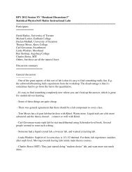
AD5171 <strong>Digital</strong> <strong>Potentiometer</strong>: <br />
A useful tutorial can be found here: http://arduino.cc/en/Tutorial/<strong>Digital</strong><strong>Potentiometer</strong> . This <br />
tutorial makes use of <strong>the</strong> AD5171 digital potentiometer, which has 64 levels of resistance (i.e., <br />
<strong>the</strong> wiper can go to 64 different positions). The pin-‐out for <strong>the</strong> AD5171 is as follows (<strong>the</strong> figure <br />
is borrowed from <strong>the</strong> tutorial): <br />
Information regarding <strong>the</strong> various pins can be found on <strong>the</strong> AD5171 datasheet: <br />
Please look at <strong>the</strong> tutorial noted above to see how <strong>the</strong> AD5171 and <strong>the</strong> <strong>Arduino</strong> should be wired <br />
up toge<strong>the</strong>r. Note that <strong>the</strong> AD0 pin is tied to ground in <strong>the</strong> tutorial. This pin is used to “address” <br />
<strong>the</strong> pot. Tying it to ground corresponds to a “zero,” while tying it to 5V corresponds to a “one.” <br />
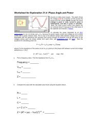
In order to “write” to <strong>the</strong> AD5171, <strong>the</strong> following bytes need to be sent (this screenshot is taken <br />
from <strong>the</strong> AD5171 datasheet): <br />
The <strong>Arduino</strong> takes care of <strong>the</strong> specifics using ones of its libraries. Here is <strong>the</strong> code used in <strong>the</strong> <br />
tutorial:
I2C <strong>Digital</strong> <strong>Potentiometer</strong> <br />
// by Nicholas Zambetti <br />
// and Shawn Bonkowski <br />
// Demonstrates use of <strong>the</strong> Wire library <br />
// Controls AD5171 digital potentiometer via I2C/TWI <br />
// Created 31 March 2006 <br />
// This example code is in <strong>the</strong> public domain. <br />
// This example code is in <strong>the</strong> public domain. <br />
#include <br />
void setup() <br />
{ <br />
Wire.begin(); // join i2c bus (address optional for master) <br />
} <br />
byte val = 0; <br />
void loop() <br />
{ <br />
Wire.beginTransmission(44); // transmit to device #44 (0x2c) <br />
// device address is specified in datasheet <br />
Wire.write(byte(0x00)); // sends instruction byte <br />
Wire.write(val); // sends potentiometer value byte <br />
Wire.endTransmission(); // stop transmitting <br />
val++; // increment value <br />
if(val == 64) // if reached 64th position (max) <br />
{ <br />
val = 0; // start over from lowest value <br />
} <br />
delay(500); <br />
} <br />
We can understand various pieces of this code by looking at Table 7, above. <br />
Wire.beginTransmission(44): This starts <strong>the</strong> transmission of data to <strong>the</strong> pot. The “44” <br />
corresponds to <strong>the</strong> “slave address byte” (i.e., <strong>the</strong> first byte) in Table 7. Sending this byte <br />
basically tells <strong>the</strong> AD5171 (as opposed to o<strong>the</strong>r devices that could be on <strong>the</strong> I2C line as well) to <br />
wake up and pay attention. The first byte in Table 7 is 010110(AD0)0. If you look in <strong>the</strong> <strong>Arduino</strong> <br />
documentation, you will see that <strong>the</strong> <strong>Arduino</strong> uses a 7-‐bit format for beginTransmission, <br />
dropping <strong>the</strong> last bit. Since we have tied AD0 to ground, it is a “0”. Thus, we use 0101100, <br />
which is 32+8+4=44. Note that we could have two AD5171 pots on <strong>the</strong> I2C line, one <strong>with</strong> AD0 at <br />
ground and one <strong>with</strong> it at 5V. In this case, we would use “44” to address one of <strong>the</strong>m and “45” <br />
to address <strong>the</strong> o<strong>the</strong>r one.
Wire.write(byte(0x00)): This corresponds to <strong>the</strong> “instruction byte” (i.e., <strong>the</strong> second byte) that is <br />
sent to <strong>the</strong> digital pot. In Table 7 this is listed as TXXXXXXX. Here T=1 would be to permanently <br />
burn <strong>the</strong> resistance setting to <strong>the</strong> pot, and X means “don’t care.” Thus, in <strong>the</strong> sample code, 0x00 <br />
is sent (in hexadecimal). <br />
Wire.write(val): Finally, <strong>the</strong> desired wiper setting is sent to <strong>the</strong> pot as a number between 0 and <br />
63. <br />
DS1803 <strong>Digital</strong> <strong>Potentiometer</strong>: <br />
The DS1803 digital potentiometers are a bit different than <strong>the</strong> AD5171s. Here is <strong>the</strong> pin-‐out, <br />
taken from <strong>the</strong> datasheet: <br />
…and here is <strong>the</strong> protocol for writing to <strong>the</strong> chip, also taken from <strong>the</strong> datasheet: <br />
In this case, <strong>the</strong> A0, A1 and A2 pins can be used to specify <strong>the</strong> specific chip to be addressed, <br />
meaning that 8 different DS1803s could be used on <strong>the</strong> same I2C line by tying <strong>the</strong>se pins to <br />
various combinations of ground and 5V. If we tie all three to ground, and strip off <strong>the</strong> last bit, <br />
we have 0101000, which is 32+8=40. Thus, transmission will be initiated <strong>with</strong>
“Wire.beginTransmission(40).” The command byte for writing to Pot-‐1 (which is <strong>the</strong> one that I <br />
had wired up) is 10101010. This is 170 in decimal or 0xaa in hexadecimal. Thus, we use <br />
“Wire.write(byte(0xaa))” to send <strong>the</strong> instruction byte. Finally, since <strong>the</strong> DS1803 is a 256-‐step <br />
pot, we can vary “val” from 0 to 255 (instead of “0 to 63,” as was <strong>the</strong> case for <strong>the</strong> AD5171). <br />
Thus, <strong>the</strong> following code should work (I also shortened <strong>the</strong> delay): <br />
#include <br />
void setup() <br />
{ <br />
Wire.begin(); // join i2c bus (address optional for master) <br />
} <br />
byte val = 0; <br />
void loop() <br />
{ <br />
Wire.beginTransmission(40); // transmit to device #40 <br />
// device address is specified in datasheet <br />
Wire.write(byte(0xaa)); // sends instruction byte <br />
Wire.write(val); // sends potentiometer value byte <br />
Wire.endTransmission(); // stop transmitting <br />
val++; // increment value <br />
if(val == 256) // if reached 256th position (max) <br />
{ <br />
val = 0; // start over from lowest value <br />
} <br />
delay(5); <br />
}