5 Rib Metal Roofing System Ordering & Installation Guide
5 Rib Metal Roofing System Ordering & Installation Guide
5 Rib Metal Roofing System Ordering & Installation Guide

You also want an ePaper? Increase the reach of your titles
YUMPU automatically turns print PDFs into web optimized ePapers that Google loves.
5 <strong>Rib</strong><br />
<strong>Metal</strong> <strong>Roofing</strong> <strong>System</strong><br />
<strong>Ordering</strong> & <strong>Installation</strong><br />
<strong>Guide</strong><br />
Specifications contained herein subject to change without notice<br />
or obligation to make changes in products previously purchased.
5 <strong>Rib</strong><br />
Table of Contents<br />
3-4 Basic Information<br />
5 Delivery, Handling and Storage<br />
5-10 Estimating and <strong>Ordering</strong><br />
11 New Roof <strong>Installation</strong><br />
12 Re-roof <strong>Installation</strong><br />
13 Fasteners<br />
15 Flashing Details Overview<br />
16 Eave Details<br />
16-18 Valley and Gable Details<br />
17 Ridge Details<br />
17 Hip Details<br />
18 Sidewall and Endwall Details<br />
19 Gambrel Details<br />
19 Pipe Flashings<br />
20-21 Skylight Details<br />
22 Chimney Details<br />
23 Key Terms<br />
2
5 RIB<br />
INSTALLATION GUIDELINES<br />
Caution: 5 <strong>Rib</strong> roofing panels must be applied on a minimum roof pitch of 2½:12 or greater.<br />
Important Notice: This guide must by read in its entirety before beginning installation.<br />
This guide is supplied by FABRAL, Inc. for use by its customers, and is intended to be a guide only. This does not replace local or<br />
state building codes.<br />
FABRAL, Inc. assumes no responsibility for any problems, which might arise as a result of improper installation or any personal<br />
injury or property damage that might occur with the products use.<br />
Under certain conditions, panels may show waviness commonly referred to as “oil canning.” This is a characteristic of<br />
roll forming. Such oil canning will not be accepted as cause for rejection.<br />
In areas of high snow or ice accumulations, snow guards, or snow blocks, may need to be added to the metal roof system<br />
to reduce or eliminate snow or ice from cascading from a higher roof and damaging lower roofs, roof valleys, gutters, or<br />
objects on the ground. Check with your installer and local building codes as to the need of snow blocks or guards in your<br />
area and design appropriately.<br />
3
MINIMUM RECOMMENDED TOOLS & EQUIPMENT<br />
Caulking Gun—Used for miscellaneous caulking and sealing to inhibit water infiltration.<br />
Chalk Line—Used to assist in the alignment of panels, flashings, etc.<br />
Electric Drill—Used to drill holes such as those required for pop rivet installation.<br />
Electric Nibblers or <strong>Metal</strong> Shears—Used for general metal cutting, such as cutting the panels in hip and valley<br />
areas.<br />
Some installers prefer using a circular saw with a metal cutting abrasive blade. This method may be faster, but it<br />
has some drawbacks:<br />
Saw cut edges are jagged and unsightly and tend to rust more quickly than sheared edges.<br />
Saw cutting produces hot metal filings that can embed in the paint and cause rust marks on the<br />
face of the panel.<br />
Saw cutting burns the paint & galvanizing at the cut edge leading to the onset of edge rust.<br />
Locking Pliers—Standard and “Duckbill” style for miscellaneous clamping and bending of parts.<br />
Marking Tools—Indelible markers, pencils, or scratching tools.<br />
Rivet Tool—Used for miscellaneous flashing and trim applications.<br />
Rubber Mallet – may be used to help snap panels together.<br />
Scratch Awl—Can be made from old screw drivers ground to a point. Used to mark the steel, open hems, and<br />
as a punch.<br />
Screw Gun—2,000 to 2,500 rpm Clutch type screw gun with a depth sensing nose piece is recommended to<br />
ensure proper installation of the screws. The following bits will be required:<br />
1/4” hex<br />
5/16” hex<br />
#2 Combination Square/Phillips bit<br />
Snips—For miscellaneous panel and flashing cutting requirements.<br />
Three pairs will be required: one for left edge, one for right edge, and one for centerline cuts.<br />
Tape Measure—25 foot minimum.<br />
Utility Knife—Used for miscellaneous cutting.<br />
4
SAFETY CONSIDERATIONS<br />
<br />
<br />
<br />
<br />
<br />
<br />
Never use unsecured or partially installed panels as a working platform. Do not walk on panels until they are in<br />
place on the roof and all of the fasteners have been installed.<br />
<strong>Metal</strong> roofing panels are slippery when wet, dusty, frosty, or oily. Do not attempt to walk on a metal roof under<br />
these conditions. Wearing soft-soled shoes will improve traction and minimize damage to the painted surface.<br />
Always be aware of your position on the roof relative to your surroundings. Take note of the locations of roof<br />
openings, roof edges, equipment, co-workers, etc.<br />
Always wear proper clothing and safety attire. Wear proper clothing when working with sheet metal in order to<br />
minimize the potential for cuts, abrasions and other injuries. Eye protection and gloves are a must when working with<br />
sheet metal products. Hearing protection should be used when power-cutting metal panels. When working on a roof,<br />
fall protection is highly recommended. Follow all OSHA Safety Requirements.<br />
Use care when operating electrical and other power equipment. Observe all manufacturers’ safety<br />
recommendations.<br />
Roof installation on windy days can be dangerous. Avoid working with sheet metal products on windy days.<br />
DELIVERY, HANDLING & STORAGE<br />
<br />
<br />
<br />
<br />
Always inspect the shipment upon delivery. Check for damage and verify material quantities against the shipping list.<br />
Note any damaged material or shortages at the time of delivery.<br />
Handle panel bundles and individual panels with care to avoid damage. Longer bundles and panels may require two<br />
or more “pick points” properly spaced to avoid damage that can result from buckling and/or bending of the panels.<br />
Store the panels and other materials in a dry, well-ventilated area, away from traffic. Elevate one end of the bundle<br />
so that any moisture that may have accumulated during shipping can run off. Be sure that air will be able to circulate<br />
freely around the bundles to avoid the build-up of moisture, if possible, separate sheets to ensure moisture is not<br />
trapped between the sheets. Never store materials in direct contact with the ground.<br />
Wear clean, non-marking, soft-soled shoes when walking on the panels to avoid shoe marks or damage to the finish.<br />
Step only in the flat area of the panels.<br />
5
ESTIMATING & ORDERING A ROOF<br />
Step 1<br />
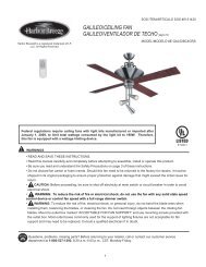
A. Sketch a birds-eye view of the roof and label each section (see example below.)<br />
F<br />
H<br />
I<br />
G<br />
E<br />
D<br />
C<br />
B<br />
A<br />
B<br />
Sketch a diagram of each roof section. Show all measurements (see example below.) It is important to measure exact<br />
center of the ridge to the eave edge. Do not allow anything for overhang.<br />
8'<br />
16'<br />
15'<br />
14'<br />
6'<br />
F<br />
40'<br />
22'<br />
H<br />
10'<br />
18' 18'<br />
I<br />
24'<br />
10'<br />
6'<br />
6'<br />
12'<br />
22'<br />
G<br />
8' 8'<br />
8'<br />
23'<br />
15'<br />
D<br />
14'<br />
30'<br />
13'<br />
30'<br />
15'<br />
18'<br />
E<br />
15'<br />
14'<br />
15'<br />
B<br />
13'<br />
10'<br />
15'<br />
C<br />
18'<br />
22'<br />
10'<br />
12'<br />
A<br />
22'<br />
Additional Information Required: Roof Pitch, Skylights (Location & Size), Chimney (Location & Size), and Size and Number of Pipe<br />
Penetrations.<br />
Additional Identification: Ridge, Hips, Valleys, Gables, Etc.<br />
6
ESTIMATING & ORDERING A ROOF (cont.)<br />
Step 2<br />
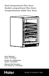
From the diagram you completed in Step 1, you are now ready to develop your roofing panel cut list. Each panel covers 36” of area<br />
so the only measurements you need are the distance from the eave to the ridge and the ridge length. You can then determine the<br />
number of panels needed by dividing the ridge length by the panel coverage. (See example Diagram A below.)<br />
DIAGRAM A<br />
25'<br />
EAVE<br />
GABLE GABLE<br />
Section A<br />
RIDGE<br />
Section B<br />
GABLE<br />
GABLE<br />
12'<br />
12'<br />
EAVE<br />
25'<br />
The length from the eave to the ridge is 12’. The length of the ridge is 25’; therefore, the number of panels to complete one side of<br />
the house is 25 ÷ 3 = 9 pcs. Your materials list should look like Sample “B”.<br />
SAMPLE B<br />
Section A—9 pcs. X 12’<br />
Now look at your roof diagram and figure out your next section of roof. Refer back to Diagram A. Section B of this sample roof is<br />
the same as Section A. Your materials list should now look like Sample C below.<br />
SAMPLE C<br />
Section A—9 pcs. X 12’<br />
Section B—9 pcs. X 12’<br />
If your home has hips or valleys, refer to Diagram 1A below.<br />
DIAGRAM 1A<br />
40'<br />
EAVE<br />
HIP<br />
VALLEY<br />
Section A<br />
30'<br />
RIDGE<br />
Section B<br />
GABLE GABLE<br />
10'<br />
10'<br />
EAVE<br />
20'<br />
EAVE<br />
RIDGE<br />
EAVE<br />
GABLE<br />
GABLE<br />
7
ESTIMATING & ORDERING A ROOF (cont.)<br />
Start with section A. The eave length is 40’ and the ridge length is 30’, with a difference of 10’. You will need 30 ÷ 3 = 10 pcs. X 10’<br />
to reach the area where the valley starts. Remember that you have 10’ remaining to cover the area. Calculate the length of each<br />
panel going into the valley by first determining the roof’s pitch. Pitch is how much rise your roof has in inches for every foot of<br />
horizontal run. Use the Hip and Valley Chart below to ensure you order the correct panel length for hips and valleys. For example,<br />
Diagram 1A is a 4/12 pitch (4/12p). According to the chart below, we know each panel will be 36 1 / 8 ” shorter. Since we are<br />
measuring from the longest point of the angle, your first piece will be the same length as the full eave to ridge measurement and<br />
each piece after will be 36 1 / 8 ” shorter. (Your list of Section A should look like Sample D below.)<br />
Hip & Valley Chart<br />
When determining the panel length needed for a hip or valley, the panel will either be shorter or longer as you go up or down the hip<br />
or valley. The chart below shows you the amount to add or subtract from each panel according to the pitch of your roof, for hips and<br />
valleys where the intersecting roof planes are at 90º to another, as in diagram 1A.<br />
1/12p = 36 1 /8” 5/12p = 39” 9/12p = 45”<br />
2/12p = 36½” 6/12p = 40¼” 10/12p = 46 7 /8”<br />
3/12p = 37” 7/12p = 41 11 /16” 11/12p = 48 13 /16”<br />
4/12p = 37 15 /16” 8/12p = 43¼” 12/12p = 50 15 /16”<br />
Note: When determining panel lengths, always round up to the next full inch.<br />
SAMPLE D<br />
Section A 11 pcs. X 10’<br />
1 pc. X 7’<br />
1 pc. X 4’<br />
1 pc. X 1’<br />
Step 3<br />
Refer to the Home Legend on page 15 for trim placement. From this diagram, you can determine the names and placement of the<br />
trim needed. All trim is produced in 10’6” sections only. Remember to allow 6” of overlap on all trims. Use the estimating section to<br />
determine trim quantities.<br />
For applications of the trim flashings, see pages 16-23.<br />
Step 3 (Cont.)<br />
8
5 <strong>Rib</strong> Estimator/Order <strong>Guide</strong><br />
Accessories<br />
Determine the total lineal feet of each condition listed below and then fill that number in on each line. Use the equations on previous<br />
pages to calculate the number of pieces for each item and circle the flashing design required.<br />
Eave ___________<br />
Gable __________<br />
Valley__________<br />
Transition _________<br />
Ridge__________<br />
Sidewall<br />
Gambrel _______<br />
Hip____________<br />
Endwall__________<br />
Skylight/Chimney width = ______<br />
Eave: ft ÷ 10 = pcs. CE-1 EAVE<br />
Ridge: ft ÷ 10= pcs AR-3 OR RR-1 RIDGE CAP<br />
Note: For vented ridge use AR3 with Profile vent (below) or AR3 with Versavent attached<br />
Gable: ft ÷ 10 = pcs RG-1 OR WG-1 GABLE TRIM<br />
Sidewall and Endwall: (____ ft. sidewall + ____ ft. endwall) ÷ 10 = _____ pcs. ASW-1 TRIM<br />
Hip: _______ ft. ÷ 10 = _______ pcs. RR-1 RIDGE CAP<br />
Valley: ft ÷ 10 = pcs RV-1 OR RV-2 W-VALLEY<br />
Slope Transition: ft ÷10 = pcs AT-1 TRANSITION TRIM<br />
Gambrel: ft ÷ 10 = pcs AT-2 GAMBREL TRIM<br />
FASTENER CALCULATIONS:<br />
Panel Screws: Quantity will vary based on spacing of fastener rows.<br />
For solid decking, use #14 x 1” MP screws.<br />
For 2 x 4 purlins, use #9 x 1” Woodfast screws<br />
Fastener Spacing Panel Screws per<br />
lineal foot of <strong>Roofing</strong><br />
12” 4.5<br />
18” 3.0<br />
24” 2.5<br />
9
ACCESSORY FASTENERS:<br />
<br />
<br />
Use #14 x 1” for Decking<br />
Use #9 x 1” for Purlins<br />
1” Fasteners<br />
(_____ ft. EAVE x 1/ft.) + (_____ ft. GABLE x 2/ft) + (_____ ft. VALLEY x 3/ft.) + (_____ ft. SKYLIGHT/CHIMNEY<br />
perimeter x 2/ft) = ________ pcs.<br />
1½” Fasteners<br />
Use #14 x 1½” for Decking<br />
Use #9 x 2” for Purlins<br />
(_____ ft. of RIDGE x 2.67/ft.) + (_____ ft. SIDEWALL x 2/ft.) + (_____ ft. ENDWALL x 1/ft) + (_____ ft. HIP x 4/ft) +<br />
(_____ ft. TRANSITION x 3/ft.) + (_____ ft. GAMBREL x 3/ft.) = ________ pcs.<br />
SEALANT CALCULATIONS:<br />
¼ X 3 / 16 X 40’ Rolls Butyl Sealant Tape<br />
(_____ ft. EAVE x 2.1’) + (_____ ft. NON-VENTED RIDGE x 4.2’) + (_____ ft. GABLE) + (_____ ft. SIDEWALL) +<br />
(_____ ft. ENDWALL x 2.1’) + (_____ ft. HIP x 4.67’) + (_____ ft. VALLEY x 4.67’) + (_____ ft. TRANSITION x 4.2’) +<br />
(_____ ft. GAMBREL x 4.2’) = ______ ft. ÷ 40’/Roll = ______ Rolls<br />
CLOSURES:<br />
1 x 1 x 19.68’ Sealer Strip<br />
(_____ ft. HIP + _____ ft. VALLEY) ÷ 9.8 = ______ pcs.<br />
OUTSIDE CLOSURE:<br />
(_____ ft. NON-VENTED RIDGE x .67 pcs./ft) + (_____ ft. ENDWALL x .33 pcs./ft.) + (_____ft. TRANSITION x .33<br />
pcs./ft.) + (_____ ft. GAMBREL x .33 pcs./ft.) + (_____ ft. SKYLIGHT/CHIMNEY x .33 pcs./ft.) = ______ pcs.<br />
INSIDE CLOSURES:<br />
(_____ ft. EAVE x .33 pcs./ft.) + (_____ ft. ENDWALL x .33 pcs./ft.) + (_____ ft. TRANSITION x .33 pcs./ft.) + (_____ ft.<br />
GAMBREL x .33 pcs./ft.) = _____ pcs.<br />
PROFILE VENT FOR VENTED RIDGE:<br />
_____ ft. of Vented Ridge ÷ 50 = ______ rolls<br />
note: available in 100’ rolls only<br />
OR<br />
USE AR3 with RX10 Versavent pre attached<br />
TOUCH-UP PAINT:<br />
______ bottles 1 oz. Touch-up paint<br />
PIPE BOOTS:<br />
GRAY EPDM<br />
Pipe Size<br />
Base Diameter Item# Min. Max.<br />
7¾” 3 ¼” 5”<br />
10¾” 5 4¼” 7½”<br />
16½” 8 7” 13”<br />
At this point, your materials list for Diagram A should look like Sample E.<br />
10
SAMPLE E<br />
Panels:<br />
Section A 9 pcs. X 12’<br />
Section B 9 pcs. X 12’<br />
Trim:<br />
6 pcs. CE-1 Eave Trim 5/12p<br />
3 pcs. RR-1 Ridge Cap 5/12p<br />
6 pcs. WG-1 Gable Trim<br />
700 pcs. #14 x 1” Panel Screws<br />
200 pcs. #14 x 1” Trim Screws<br />
100 pcs. #14 x 1.5” Trim Screws<br />
4 Rolls Butyl Sealant Tape<br />
17 pcs. Inside Closure<br />
1 Roll (100’) Profile Vent GR3/AT<br />
1 pc. #3 Pipe Boot<br />
You are now ready to order your new metal roof. If you have any questions, or need you materials list checked, please contact your<br />
local FABRAL Distributor.<br />
Panels:<br />
Color = ___________<br />
______ pcs. @ ______ ft. ______ in.<br />
______ pcs. @ ______ ft. ______ in.<br />
______ pcs. @ ______ ft. ______ in.<br />
______ pcs. @ ______ ft. ______ in.<br />
______ pcs. @ ______ ft. ______ in.<br />
______ pcs. @ ______ ft. ______ in.<br />
______ pcs. @ ______ ft. ______ in.<br />
5 <strong>Rib</strong>® Order Form<br />
Accessories:<br />
______ pcs. of Eave Flash ______ (flashing code)<br />
______ pcs. of Ridge Flash ______<br />
______ pcs. of Gable Flash ______<br />
______ pcs. of Sidewall Flash ______<br />
______ pcs. of Endwall Flash ______<br />
______ pcs. of Valley Flash ______<br />
______ pcs. of Transition Flash ______<br />
______ pcs. of Gambrel Flash ______<br />
______ pcs. of Peak Flash ______<br />
______ pcs. of J Channel ______<br />
______ pcs. of #14 x 1” or 1½” MP Painted Screws<br />
______ pcs. of Tube Caulk<br />
______ pcs. of Butyl Sealant Tape<br />
______ pcs. 1 x 1 x 13.2’ Sealer Strip<br />
11
NEW ROOFS<br />
1. Make sure there are no nails or other objects protruding from the substrate that might puncture the underlayment or damage<br />
the roof panels. Clean all debris from the deck. Check for any high or low spots in the deck, which will cause waviness in the<br />
metal panels.<br />
2. Check all details for possible roof penetrations, which must be added to the deck prior to roof panel installation (vented ridge for<br />
example).<br />
3. Cover the entire roof deck with 30-pound felt paper, Typar or equivalent (hereinafter referred to as underlayment). Begin at the<br />
eave at the gable end and roll out the underlayment horizontally (parallel to the eave). Allow each consecutive course to<br />
overlap the previous one at least 4”. Overlap the end a minimum of 6” when starting a new roll of underlayment. Areas of<br />
underlayment that have been torn or cut should be replaced or repaired prior to installation of the metal roof. (See Illustration<br />
#1 below)<br />
ILLUSTRATION #1<br />
6"<br />
UNDER<br />
LAYMENT<br />
3"<br />
4. Place an alignment line along the gable end where the first roof panel will be installed. THIS LINE SHOULD BE LOCATED 1/2”<br />
IN FROM THE GABLE EDGE OF THE ROOF DECK AND SQUARE WITH THE EAVE LINE. Various methods exist for<br />
insuring that the line is square. Call your nearest FABRAL representative if you need assistance. (See Illustration #2)<br />
ILLUSTRATION #2<br />
1/2"<br />
ALIGNMENT LINE<br />
DIRECTION OF<br />
PANEL APPLICATION<br />
LINE MUST BE<br />
SQUARE WITH EAVE<br />
12
EXISTING ROOFS<br />
In many cases, FABRAL’s Steel <strong>Roofing</strong> Panels can be installed over existing roofing without tear-off of the old roofing.<br />
Check with your local codes or building department for the specific requirements in your area.<br />
If the roof is to be stripped down to the existing decking, follow the procedures for new roofs on page 12. Be sure to check the<br />
existing roof and repair any damaged areas prior to installation of the new roof system.<br />
The following steps should be taken when installing new metal roof panels over existing roofing.<br />
1. Inspect the roof for damage and make the necessary repairs.<br />
2. Secure any warped or loose roofing.<br />
3. Make sure there are no nails or other objects protruding from the roof that might puncture the new underlayment or<br />
damage the new roof panels.<br />
4. Remove all moss and other debris from the roof.<br />
5. Cut off any overhanging roofing flush with the roof deck, and remove all hip and ridge caps.<br />
6. Install 2x4 Purlins @ 24” o.c. to attach the panels or follow the directions on page 12, #2 through #4, on roof preparation.<br />
Note: For best results, <strong>Metal</strong> <strong>Roofing</strong> requires a relatively smooth and flat substrate. Application over rough and/or<br />
uneven surfaces is not recommended.<br />
PANEL INSTALLATION<br />
Note: Prior to panel installation, determine which items need to be installed prior to panels (such as eave, valley, swept wing, etc.)<br />
1. Working off the eave edge, establish a straight line up the gable edge from which you are starting. This will insure that the<br />
first panel laid will be straight and square with the eave. (See Illustration #2 on page 12)<br />
2. Before fastening the panel to the roof deck, check to make sure that the panel is overhanging the eave by 1”.<br />
3. Once the first panel is in proper position, secure it to the roof deck with #14 fasteners per the standard fastening pattern.<br />
4. Set the gable trim into a bead of butyl tape and screw it to the fascia board (see pages 16-17). This fully secures the first<br />
panel to the roof deck.<br />
5. Position the second panel (overlap edge on top of the underlap edge of first panel) assuring that the eave edge is in<br />
position (1” overhang). Secure the second panel to the deck with #14 fasteners.<br />
6. Each consecutive panel will be installed in the same manner.<br />
13
5 RIB®<br />
FASTENERS<br />
Fasteners Description Use<br />
Note the diagram below for proper installation of gasketed fasteners.<br />
#9 x 1" Woodfast<br />
Roof Panels attached to<br />
Purlins and Trim; Siding<br />
attached to wood girts<br />
PROPER INSTALLATION OF GASKETED FASTENERS<br />
#14 x 1" Woodtite<br />
#9 x 2" Woodfast<br />
Roof Panels attached to<br />
OSB or Plywood and<br />
Trim; Siding attached to<br />
plywood<br />
Attaching ridge cap and<br />
other trim through the<br />
top of the rib with 1x or<br />
2x material<br />
#14 x 2" Woodfast Attaching ridge cap and<br />
other trim through the<br />
top of the rib with OSB<br />
or plywood<br />
correctly driven under-driven over-driven<br />
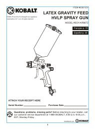
Load Span Tables for 29 ga. 5 <strong>Rib</strong><br />
ALLOWABLE LIVE LOAD (psf) for 29 ga. 80 ksi PANELS Purlin Or Nailer Spacing (ft.)<br />
Spans 1.0 1.5 2.0 2.5 3.0<br />
3 OR<br />
MORE<br />
Load<br />
(psf)<br />
450 200 112 72 50<br />
Note: Live loads are based on panel load capacity only and do not<br />
apply to load capacity of trusses, purlins, or decking.<br />
LOAD SPAN TABLE FOR 29 GA. 5 RIB<br />
ALLOWABLE WIND UPLIFT LOADS (psf)<br />
Substrate Fastener 9” 12” 15” 18” 21” 24”<br />
¾” Plywood #14 x 1” MP 275.6 206.7 165.4 137.8 118.1 103.4<br />
5/8” Plywood #14 x 1” MP 160 120 96 80 68.6 60<br />
½” Plywood #14 x 1” MP 135.9 101.9 81.5 67.9 58.2 51<br />
7/16” OSB #14 x 1” MP 61.5 46.1 36.9 30.7 26.3 23.1<br />
19/32” OSB #14 x 1” MP 100.7 75.5 60.4 50.3 43.1 37.8<br />
23/32” OSB #14 x 1” MP 115.9 86.9 69.5 57.9 49.7 43.5<br />
Solid 2x SPF #9 x 1” WF 218.7 164.0 131.2 109.3 93.7 82<br />
Solid 1x Pine #9 x 1” WF 168.4 126.3 101 84.2 72.2 63.2<br />
Screws per Sq. 190 150 120 100 90 80<br />
*Maximum 24” spacing<br />
Intermediate Roof Purlins and All Siding<br />
Eaves and Endlaps - Roof Purlins<br />
Listed above are the fasteners recommended for the proper installation of the <strong>Metal</strong> panels.<br />
14
5 RIB INSTALLATION GUIDE<br />
GABLE/RAKE<br />
VAL LEY<br />
RIDGE/P EAK<br />
PIPE PENETRATION<br />
SIDEWA LL<br />
EAVE<br />
ENDWALL<br />
GABLE/RAKE<br />
HIP<br />
MONOSLOPE RIDGE CP-1<br />
RESIDENTIAL GABLE RG-1<br />
RIDGE AR-3<br />
DENVER EAVE CE-1<br />
SIDEWALL/ENDWALL FLASH<br />
ASW-1<br />
TRANSITION FLASH AT-1<br />
RESIDENTIAL GABLE WG-1<br />
VALLEY RV-1<br />
GAMBREL AT-2<br />
VALLEY RV-2<br />
RESIDENTIAL RIDGE/HIP FLASH RR-1<br />
15
EAVE DETAIL<br />
FASTENER<br />
CE-1<br />
FASTENER<br />
@ 12" C/C<br />
BUTYL TAPE<br />
TOP & BOTTOM<br />
OF CLOSURE<br />
29 GA. AGRI PANEL<br />
ROOF STRUCTURE<br />
INSIDE<br />
CLOSURE<br />
Notes:<br />
1. <strong>Roofing</strong> underlayment not shown.<br />
2. Tack the eave flashing in place under the underlayment<br />
using roofing nails.<br />
3. Install the panels and closures as shown, allowing ½” to<br />
1” of hang at eave.<br />
29 GA. AGRI PANEL<br />
SCREWS<br />
EACH SIDE OF MAIN<br />
RIB (EAVE/ENDLAP<br />
PATTERN) AND<br />
ONE ADDITIONAL,<br />
CENTRALLY LOCATED<br />
IN THE PAN OF THE<br />
PANEL.<br />
RV-1 OR<br />
RV-2 (SHOWN)<br />
BUTYL SEALANT<br />
TOP & BOTTOM<br />
OF SEALER STRIP<br />
CUT PANEL AS<br />
NECESSARY<br />
ROOF STRUCTURE<br />
PLYWOOD OR<br />
SOLID SUPPORT<br />
4" MINIMUM<br />
VALLEY DETAIL<br />
SEALER STRIP,<br />
1"x1"x13'<br />
BLOCK CLOSURE<br />
FILLS RIB VOIDS<br />
ROOF FELT AND<br />
ICE & WATER SHIELD<br />
Notes:<br />
1. <strong>Roofing</strong> underlayment not shown.<br />
2. Place a second layer of 36” roofing underlayment in the<br />
centerline of the valley with 18” of underlayment on each<br />
side of the valley.<br />
3. When valley flashing is overlapped, 6” of lap is<br />
recommended with sealant applied under the lap.<br />
4. Install sealant and 1 x 1 x 19’ sealer strip as shown.<br />
5. Field cut the roofing panels holding back 4”-6” from<br />
valley as shown.<br />
6. Fasten the panels through the valley flashing as shown<br />
with fasteners on both sides of each main rib. In<br />
applications with extreme angles, an additional fastener<br />
may be needed between ribs.<br />
START GABLE DETAIL<br />
RG-1, OR<br />
WG-1<br />
SCREW<br />
FASTENER<br />
@ 12" C/C<br />
BUTYL TAPE<br />
29 GA. AGRI PANEL<br />
ROOF STRUCTURE<br />
BUTYL TAPE<br />
29 GA. AGRI PANEL<br />
ROOF STRUCTURE<br />
CUT PANEL AS<br />
NECESSARY<br />
RG-1, OR<br />
WG-1<br />
FINISH GABLE DETAIL<br />
SCREW<br />
FASTENER<br />
@ 12" C/C<br />
16<br />
Notes:<br />
1. <strong>Roofing</strong> underlayment not shown.<br />
2. Install the gable trim by placing it over the edge of the<br />
roof as shown and fasten it to the fascia board at 12” on<br />
center.<br />
3. The eave end of the gable-trim can be closed-off by<br />
snipping and folding.<br />
4. For gable detail at ridge, see page 17.<br />
5. When the last roof panel extends past the roof, trim<br />
panel and finish as shown.
RIDGE & GABLE DETAILS<br />
RIDGE DETAIL<br />
RIDGE<br />
SEALANT IS USED BETWEEN<br />
RIDGE & GABLE AND<br />
UNDER GABLE LAP<br />
#14 x 1 1/2" LONG<br />
FASTENER 9" C/C MAX<br />
RIDGE CAP<br />
RR-1 or AR-3<br />
FASTENER<br />
29 GA. AGRI<br />
PANEL<br />
ROOF STRUCTURE<br />
GABLE TRIM<br />
SEALANT TAPE<br />
TOP & BOTTOM OF<br />
OUTSIDE CLOSURE<br />
VENTED RIDGE<br />
Note: RX10 Versavent can be used instead of Profilevent (shown)<br />
#14 x 1 1/2" LONG FASTENER<br />
9" C/C MAX<br />
PROFILE VENT<br />
RIDGE CAP<br />
AR-3<br />
29 GA. AGRI PANEL<br />
ROOF STRUCTURE<br />
Notes:<br />
1. <strong>Roofing</strong> underlayment not shown.<br />
2. Plywood should be held back or cut back 1½” from each side of the ridge.<br />
3. Attach the panels checking the 1” minimum overhang at the eave.<br />
4. Mark edge of ridge cap on both sides of the peak. Unroll profile vent and press into place about 1” upslope of mark.<br />
5. The gable flashing must be installed prior to the ridge installation.<br />
6. Fasten the ridge cap using #14 x 1½” MP screws on each panel rib 1” back from the edge of the profile vent<br />
HIP DETAIL<br />
HIP ROOF—PLAN VIEW<br />
#14 x 1 1/2" LONG<br />
FASTENER 9" C/C MAX<br />
RIDGE CAP<br />
RR-1 or AR-3<br />
HIP CAP<br />
29 GA. AGRI<br />
PANEL<br />
29 GA. AGRI PANEL<br />
ROOF STRUCTURE<br />
SEALANT TAPE<br />
TOP & BOTTOM OF<br />
SEALER STRIP<br />
Note:<br />
1. Hip flashing attachment same as ridge (see detail above).<br />
17
MONOSLOPE PEAK<br />
OUTSIDE CLOSURE<br />
2" LONG FASTENER<br />
AT EVERY RIB<br />
(9" O.C.)<br />
SEALANT TAPE<br />
TOP & BOTTOM OF<br />
CLOSURE OR SEALER<br />
STRIP<br />
29 GA. ARGI PANEL<br />
CP-1<br />
ROOF STRUCTURE<br />
30# ROOFING FELT<br />
Notes:<br />
1. <strong>Roofing</strong> underlayment not shown.<br />
2. Apply sealant to the bottom of the foam closure and<br />
position it on the roof panel approximately ½” - 1” back<br />
from the edge of the flashing as shown.<br />
3. Apply sealant to the top of the foam closure.<br />
4. Install flashing as shown.<br />
5. When more than one length of flashing is used, a 6”<br />
minimum overlap is recommended. Apply sealant<br />
between the laps<br />
ENDWALL DETAIL<br />
FLASH ASW-1<br />
29 GA. AGRI PANEL<br />
FASTENER<br />
@ 9" C/C<br />
Notes:<br />
1. <strong>Roofing</strong> underlayment not shown.<br />
2. Install the foam closure as shown using sealant on the<br />
top and bottom.<br />
3. Install endwall flashing as shown.<br />
4. When more than one endwall is needed, a 6” minimum<br />
overlap is recommended with sealant between the laps.<br />
OUTSIDE CLOSURE<br />
BUTYL TAPE<br />
TOP & BOTTOM<br />
OF CLOSURE<br />
SIDEWALL DETAIL<br />
INSIDE CLOSURE<br />
FASTENER<br />
BUTYL SEALANT<br />
TOP OF BOTTOM<br />
OF CLOSURE<br />
ASW-1<br />
FASTENER<br />
@ 9" C/C<br />
BUTYL SEALANT<br />
29 GA. AGRI PANEL<br />
Notes:<br />
1. <strong>Roofing</strong> underlayment not shown.<br />
2. The sidewall flashing is placed over the panel rib and<br />
placed behind the siding as shown.<br />
3. When the panel rib does not end up next to the wall, cut<br />
the panel and bend a 1” return flange.<br />
ROOF SHEATHING<br />
SWEPT WING GABLE<br />
ROOF FELT<br />
BUTYL SEALANT TAPE<br />
TOP & BOTTOM OF<br />
SEALER STRIP<br />
SEALER STRIP<br />
(ASPHALT IMPREGNATED)<br />
CE-1 FLASH<br />
FASCIA BOARD<br />
FASTENER<br />
Note:<br />
1. In high rain & snow areas, FABRAL recommends that a<br />
high-grade underlayment, such as ice and water shield,<br />
be placed along the entire swept wing gable.<br />
2. <strong>Roofing</strong> underlayment not shown.<br />
3. Install the 1 x 1x 13’ sealer strip with a bead of butyl<br />
sealant tape top and bottom.<br />
4. Cut panels to fit the gable angle and align downslope<br />
edge.<br />
5. Fasten the panels through the flashing and into the deck<br />
using #14 Mill Point screws per the standard eave<br />
fastening pattern.<br />
18
GAMBREL DETAIL<br />
BUTYL SEALANT TAPE<br />
TOP & BOTTOM<br />
OF CLOSURE<br />
FASTENER<br />
INSIDE CLOSURE<br />
ROOF STRUCTURE<br />
AT-2<br />
FASTENER<br />
BUTYL SEALANT TAPE<br />
TOP & BOTTOM<br />
OF CLOSURE<br />
ROOF PANEL<br />
OUTSIDE CLOSURE<br />
Notes:<br />
1. <strong>Roofing</strong> underlayment not shown.<br />
2. Bottom panels of the slope transition must be<br />
installed first.<br />
3. Mark the location of the foam closure and place a bead<br />
of butyl sealant tape on the panels. Install the closures<br />
and a second bead of sealant on top of the closures.<br />
4. Install AT-1 Transition trim using #14 x 1½” MP screws<br />
into each rib of the bottom transition panels, 9” o.c.<br />
5. Apply sealant as indicated.<br />
SLOPE TRANSITION (WOOD FRAMING)<br />
29 GA. AGRI PANEL<br />
FASTENER<br />
@ 9" C/C<br />
INSIDE CLOSURE<br />
FLASH AT-1<br />
OUTSIDE CLOSURE<br />
BUTYL TAPE<br />
TOP & BOTTOM<br />
OF CLOSURE<br />
PIPE FLASHING<br />
(OPTIONAL) SILICONE<br />
SEALANT AROUND<br />
CUT OF BOOT<br />
29 GA. AGRI PANEL<br />
BUTYL SEALANT TAPE<br />
UNDER BASE OF<br />
PIPE BOOT<br />
PLYWOOD DECK<br />
VENTILATION<br />
PIPE<br />
PIPE BOOT<br />
SCREWS SPACED 2" TO 3" MAX<br />
AROUND BASE TO SECURE<br />
Notes:<br />
1. Cut the hole in the flashing 20% smaller than the<br />
pipe diameter.<br />
2. Slide the flashing down the pipe.<br />
3. Form the flashing to the roof profile.<br />
4. Apply sealant around the perimeter of the flashing base<br />
and fasten to roof using #14 x 1” fasteners.<br />
19
CRICKET FIELD FORMED<br />
UNIT<br />
WIDTH<br />
VERTICAL<br />
BEND<br />
RIDGE<br />
2" MIN.<br />
FLANGE CAP<br />
2" MIN.<br />
FLAT<br />
STOCK<br />
Notes:<br />
1. Trim both ends of the uphill and downhill sides of the<br />
skylight flashing as indicated.<br />
2. Slide the uphill flashing into the slots cut into the roofing<br />
and apply a liberal amount of sealant.<br />
3. Assemble the skylight as indicated on pages 20-21.<br />
2" MIN<br />
4. Trim and assemble chimney flashing similarly.<br />
UNIT<br />
HEIGHT<br />
FLANGE CAP<br />
2" MIN.<br />
VERTICAL<br />
FLANGE<br />
2" MIN.<br />
OVERALL HEIGHT TO BE<br />
MIDWAY PLUS ON HEAD<br />
JAMB<br />
2" MIN<br />
B<br />
B<br />
A<br />
PROCEDURE FOR THE INSTALLATION OF SKYLIGHT FLASHING<br />
A<br />
CRICKET FIELD<br />
FORMED<br />
Notes:<br />
1. Whenever possible, position the skylight curb so the ribs<br />
of the roof panels do not interfere with the flashing.<br />
2. Cut the roofing panels as close to the left, right and<br />
downhill sides of the curb as possible. Cut the uphill<br />
side within 1” of the valley formed by the cricket.<br />
C<br />
3. The skylight flashings should be 4” wider than the width<br />
of the curb (2” on each side).<br />
C<br />
4. Install with 1 x 1 sealer and sealant per Detail B-B on<br />
page 21.<br />
20
SKYLIGHT FLASHING PREPARATION<br />
SASH<br />
FRAME<br />
SCREEN<br />
JAMB<br />
Detail A-A<br />
SEALANT<br />
FLASHING ASW-1 - FIELD MODIFY<br />
AS REQUIRED<br />
FASTENER<br />
SEALANT 29 GA. AGRI PANEL<br />
ROOF SHEATHING<br />
ROOF FRAMING<br />
FLASHING -REVERSE<br />
AL FLASHING<br />
CONTINUOUS SIKAFLEX<br />
CAULK @ PERIMETER<br />
ALTERNATE DETAIL A-A<br />
SEALANT<br />
SEALANT TAPE<br />
BETWEEN FLASH<br />
AND ROOF PANEL<br />
FASTENER @ 6" C/C<br />
29 GA. AGRI PANEL<br />
ICE AND WATER<br />
SHIELD AND 30# FELT<br />
OR ROOFGUARD<br />
UNDERLAYMENT<br />
Notes:<br />
1. Trim and bend the right side skylight flashing to fit as necessary.<br />
2. Trim the left side in a similar fashion.<br />
1/2" PLYWOOD<br />
1/2" RIGID INSULATION<br />
SEALANT<br />
SASH<br />
SKYLIGHT<br />
DETAIL B-B<br />
CUSTOM DIVERTER FLASH<br />
CONTINUE SUCH THAT<br />
THE DIVERTER AND<br />
VALLEY FLASH OVERLAP<br />
5" MIN<br />
29 GA. AGRI PANEL<br />
INSIDE CLOSURE<br />
SEALANT TAPE<br />
TOP & BOTTOM<br />
OF CLOSURE<br />
SKYLIGHT FLASHING (SIDE)<br />
DETAIL C-C<br />
ASW-1 FLASHING<br />
FIELD MODIFIED<br />
TO FIT<br />
#10 x 2" WOODGRIP<br />
FASTENER 9" O.C.<br />
BUTYL TAPE<br />
TOP & BOTTOM<br />
OF CLOSURE<br />
29 GA. AGRI PANEL<br />
SASH<br />
SEALANT<br />
FRAME<br />
FRAME<br />
DRYWALL<br />
PLYWOOD<br />
ROOF SHEATHING<br />
BATT INSULATION<br />
#10x1 1/2" WOODGRIP<br />
FASTENER<br />
6" O.C. MAX<br />
ROOF SHEATHING<br />
OUTSIDE CLOSURE<br />
HEADER<br />
FASTENER<br />
21
CHIMNEY FLASHING<br />
ENDWALL FLASH<br />
CRICKET FIELD<br />
MADE FROM<br />
FLAT SHEET<br />
Notes:<br />
1. Procedures for the installation of Chimney Flashings are<br />
similar to the Skylight’s (refer to pages 20-21).<br />
2. The saw-cut reglet shown provides the best weathertight<br />
installation for chimneys. Fill the reglet with sealant,<br />
insert trim and fasten as necessary w/masonry anchors.<br />
3. Flashings may be field-formed from 40 13 / 16 ” x 10’ flat<br />
sheets.<br />
SIDEWALL FLASH<br />
CHIMNEY FLASHING (SIDE)<br />
CHIMNEY FLASHING (UPHILL SIDE)<br />
AL FLASHING<br />
SAW CUT REGLET<br />
1/2" - 1" DEEP<br />
BLOW OUT DUST & FILL WITH SIKAFLEX<br />
SEALANT. SET FLASH & FASTEN WITH<br />
COMPATIBLE MASONRY ANCHOR<br />
FLASHING -REVERSE<br />
AL FLASHING<br />
CONTINUOUS SIKAFLEX<br />
CAULK @ PERIMETER<br />
FASTENER @ 6" C/C<br />
29 GA. AGRI PANEL<br />
ICE AND WATER SHIELD AND<br />
30# FELT OR ROOFGUARD<br />
UNDERLAYMENT<br />
ROOF SHEATING<br />
SEALANT TAPE<br />
BETWEEN FLASH<br />
AND ROOF PANEL<br />
SAW CUT REGLET<br />
1/2" - 1" DEEP<br />
BLOW OUT DUST & FILL WITH SIKAFLEX<br />
SET FLASH & FASTEN WITH COMPATIBLE<br />
MASONRY ANCHOR<br />
FLASHING ASW-1 - FIELD MODIFY<br />
AS REQUIRED<br />
FASTENER<br />
SEALANT<br />
AL FLASHING<br />
SEALANT<br />
29 GA. AGRI PANEL<br />
ROOF SHEATING<br />
SEALANT<br />
ALTERNATE FLASHING<br />
ALTERNATE FLASHING<br />
CHIMNEY FLASHING (DOWNHILL SIDE)<br />
1/2" PLYWOOD<br />
1/2" RIGID INSULATION<br />
CUSTOM DIVERTER FLASH<br />
CONTINUE SUCH THAT<br />
THE DIVERTER AND<br />
VALLEY FLASH OVERLAP<br />
5" MIN<br />
29 GA. AGRI PANEL<br />
INSIDE CLOSURE<br />
SEALANT TAPE<br />
TOP & BOTTOM<br />
OF CLOSURE<br />
CHIMNEY (ALTERNATE SIDE)<br />
SAW CUT REGLET<br />
1/2" - 1" DEEP<br />
BLOW OUT DUST & FILL WITH SIKAFLEX<br />
SET FLASH & FASTEN WITH COMPATIBLE<br />
MASONRY ANCHOR<br />
ASW-1 FLASHING<br />
FIELD MODIFIED<br />
TO FIT<br />
#10 x 2" WOODGRIP<br />
FASTENER 9" O.C.<br />
BUTYL TAPE<br />
TOP & BOTTOM<br />
OF CLOSURE<br />
29 GA. AGRI PANEL<br />
ROOF SHEATING<br />
#10x1 1/2"<br />
BATT INSULATION<br />
WOODGRIP<br />
FASTENER<br />
SAW CUT REGLET<br />
6" O.C. MAX<br />
1/2" - 1" DEEP<br />
BLOW OUT DUST & FILL WITH SIKAFLEX<br />
SET FLASH & FASTEN WITH COMPATIBLE<br />
MASONRY ANCHOR<br />
ROOF SHEATHING<br />
OUTSIDE COLSURE<br />
FASTENER<br />
AL FLASHING<br />
SEALANT<br />
ALTERNATE FLASHING<br />
22
STANDARD TRIM PARTS<br />
See page 15 for<br />
Illustration of Trim Conditions<br />
Key Terms<br />
CHIMNEY OR SKYLIGHT<br />
See pages 20-22<br />
EAVE TRIM<br />
This piece is used at the eave or gutter edge of the building, and must be installed before any panels.<br />
ENDWALL<br />
This piece is used when the upper end of panel butts into a vertical wall.<br />
FASTENERS- OSB & Plywood<br />
#14 X 1” MILL POINT SCREW<br />
This fastener is used to attach trim to the panels, and also to attach panels directly to the roof deck.<br />
#14 x 2” MILL POINT SCREW<br />
This fastener is used to attach trim through the high rib of the panel, and also to attach panels to the roof deck.<br />
FASTENERS- 1x or 2x Solid Lumber<br />
#9 X 1” MILL POINT SCREW<br />
This fastener is used to attach trim to the panels, and also to attach panels directly to the roof deck.<br />
#9 x 2” MILL POINT SCREW<br />
This fastener is used to attach trim through the high rib of the panel, and also to attach panels to the roof deck.<br />
GABLE TRIM<br />
This piece is installed on the house between the ridge and the eave, holding down the first panel edge and the last panel<br />
edge. Gable-trim seals out the weather and gives a neat finished appearance.<br />
GAMBREL CONDITION - AT-2<br />
This trim is used to transition from low-slope panels on the top section to steep-slope panels on the lower section.<br />
HIP CAP<br />
This piece covers projecting angles formed at the intersection of the two sloping roof planes.<br />
MONOSLOPE PEAK CAP - CP-1<br />
This piece is used at the top of a single sloped roof.<br />
RIDGE CAP<br />
This piece is used at the peak of a typical two-slope roof. The ridge can be ventilated, by using Profile Vent in place of<br />
sealant and outside closures.<br />
SIDEWALL<br />
This piece is used when the roofing panel is installed parallel to a vertical wall.<br />
SLOPE TRANSITION - AT-1<br />
This piece is used where two roofs of different pitch meet, the top section being steeper than the lower section.<br />
W-VALLEY<br />
Used to flash the valley formed by intersecting roof planes.<br />
This list of flashing can be used in conjunction with the Home Legend drawing on page 15 to help you understand placement and proper installation.<br />
23
Headquarters:<br />
Lancaster Plant:<br />
3449 Hempland Road<br />
Lancaster, PA 17601<br />
(800)477-2741 Fax (800)283-4289<br />
Other Manufacturing Facilities:<br />
Gridley Plant:<br />
Rt. 24 West<br />
Gridley, IL 61744<br />
(800)451-3974 Fax (800)289-3383<br />
Jackson Plant:<br />
308 Alabama Blvd.<br />
Jackson, GA 30233<br />
(800)884-4484 Fax (800)765-4484<br />
Tifton Plant:<br />
Hwy 41 South & 55 Lamp Loop<br />
Tifton, GA 31793<br />
(800)749-8144 Fax (800)380-4784<br />
Idabel Plant:<br />
Rt. 3 Box 632<br />
Idabel, OK 74745<br />
(800)926-8509 Fax (800)289-6007<br />
Cedar City Plant:<br />
2402 Industry Way<br />
Cedar City, UT 84720<br />
(800)432-2725 Fax (800)632-2725<br />
Salem Plant:<br />
4570 Ridge Drive, N.E.<br />
Salem, OR 97303<br />
(800)477-9124 Fax (503)393-5813<br />
Saint Joseph Plant:<br />
600 15th Avenue N.E.<br />
Saint Joseph, MN 56374<br />
(800) 873-3440 Fax (320) 363-0553<br />
LOW-21 © 2011 FABRAL (98-32-725) 10/11<br />
24