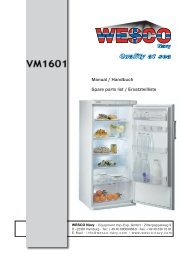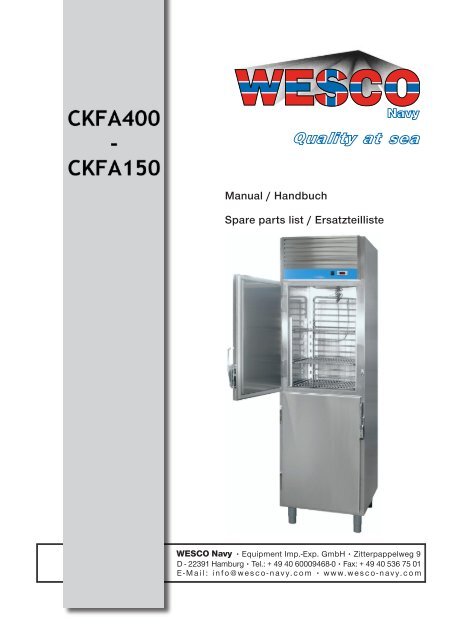
Manual / Handbuch Spare parts list / Ersatzteilliste - WESCO-Navy
Manual / Handbuch Spare parts list / Ersatzteilliste - WESCO-Navy
Manual / Handbuch Spare parts list / Ersatzteilliste - WESCO-Navy

You also want an ePaper? Increase the reach of your titles
YUMPU automatically turns print PDFs into web optimized ePapers that Google loves.
<strong>Manual</strong> / <strong>Handbuch</strong><br />
<strong>Spare</strong> <strong>parts</strong> <strong>list</strong> / Ersatzteil<strong>list</strong>e<br />
• Equipment Imp.-Exp. GmbH • Zitterpappelweg 9<br />
D - 22391 Hamburg • Tel.: + 49 40 60009468-0 • Fax: + 49 40 536 75 01<br />
E - M a i l : i n f o @ w e s c o - n a v y. c o m • w w w. w e s c o - n a v y. c o m
Contents:<br />
Page<br />
Installation instructions<br />
User instructions<br />
3<br />
4-5<br />
Cleaning/general maintenance 6<br />
Installer’s obligations in connection with<br />
installation 7-8<br />
Figures 9<br />
Trouble Shooting 10<br />
Compressor windings resistance 11<br />
Drawings 12-13<br />
<strong>Spare</strong> part <strong>list</strong> 14<br />
Controller 15-24<br />
Wiring diagram 25<br />
General instructions<br />
1. Read the contents of this manual carefully. It contains important information concerning the installation, use and<br />
maintenance of the equipment.<br />
Keep this manual in a safe place but also ensure that it is available to everyone who will use the equipment.<br />
2. The equipment may only be installed by qualified, authorised personnel in accordance with the manufacturer’s<br />
instructions.<br />
3. If a fault should occur, switch off the power supply immediately and remove the plug from the wall socket.<br />
Contact the manufacturer (during the warranty period) or another person or company authorised by the<br />
manufacturer to repair the equipment.<br />
Use only original <strong>parts</strong> when replacing components.<br />
If the above is not observed, the safety of the equipment may be at risk and it may be more difficult to rely on the<br />
warranty on a subsequent occasion.<br />
The equipment has been tested and certified by SEMKO where CE marking and EMC are concerned.<br />
Or by the manufacturer with reference to the rules and regulations that apply to CE and EMC approval.<br />
2
Installation instructions<br />
Location<br />
• The equipment must be installed in a well-ventilated room (fig. 1), as far as possible from heat sources<br />
and so that good air circulation is achieved, in particular around the part where the compressor unit is<br />
located. The maximum room temperature may not exceed +32 o C and the condensation temperature<br />
may not exceed +45 o C.<br />
• Adjust the height and the horizontal and vertical inclination of the equipment by rotating the adjustable<br />
legs and check that the door can be opened and closed without impediment.<br />
• The equipment must be anchored in a suitable manner to prevent it from tipping over.<br />
• Remove the protective plastic from the external surfaces on models made of stainless sheeting. Pull the<br />
plastic off slowly. If, after the plastic has been removed, there is any glue residue, it can be removed<br />
with a suitable solvent.<br />
Electrical connection<br />
Electrical connections must be made in accordance with all applicable local standards and regulations in<br />
force at the time.<br />
• The electrical connection must be made in accordance with all applicable standards and regulations.<br />
- The equipment works from single-phase 220-240 V AC 50 Hz<br />
- The equipment is connected simply by inserting the plug in the mains socket after checking<br />
that the mains socket can be loaded with the relevant current and has the correct protective<br />
earthing.<br />
- All standard version units are protected with a 10 A delay action fuse.<br />
- A 3 m power cable is supplied. This emerges from the unit or solenoid valve at a height above<br />
the floor of roughly 2000 mm.<br />
• The electrical safety of the equipment can only be guaranteed when it has been correctly connected to<br />
an installation with protective earthing in accordance with applicable safety regulations.<br />
• If you have any doubt about the efficiency of the protective earthing, the installation must be checked<br />
by a qualified engineer.<br />
The manufacturer accepts no liability for the consequences of the above safety measures not being taken.<br />
Page 2<br />
3
User instructions<br />
Comments:<br />
• The equipment may only be used for the purpose for which it was manufactured, which involves the<br />
refrigeration or preservation of food. All other use of the equipment must be regarded as incorrect.<br />
• To ensure that the equipment functions correctly:<br />
- ensure that all food is covered or wrapped<br />
- leave sufficient space between the shelves and the sides of the equipment to maintain<br />
adequate air circulation<br />
- do not leave doors or boxes open for a long time<br />
Control panel (fig. 2), standard version.<br />
A-On/off switch<br />
B-Digital thermostat<br />
Standard models, switching on<br />
Press the switch. A lamp in the switch lights up to show that the unit is switched on.<br />
Set the digital thermostat to the required temperature. Do this as follows:<br />
Press the SET button. The preset temperature is displayed in the display.<br />
Press the button to increase the temperature shown. If you hold the button in, the temperature values will<br />
increase rapidly.<br />
The<br />
button reduces the temperature in the same way.<br />
Five seconds after you release the button, the new value is automatically saved in the memory and the thermostat<br />
displays the temperature inside the refrigeration area. The preset ranges for minimum and maximum<br />
temperatures are:<br />
Refrigeration: Max. setting = +12 o Min. setting = 0 o<br />
Chiller: = +12 o = 0 o<br />
Freezer: = -10 o = -30 o<br />
Cooling: = +12 o = 0 o<br />
When the unit is in operation, the digital thermostat displays the internal temperature.<br />
Press the SET button to display the programmed temperature in the display.<br />
Page 3<br />
4
Defrosting<br />
1. Automatic defrosting<br />
The unit has an automatic defrosting system (not bakery freezers). When this is activated, the DEF indicator<br />
lights up on the digital thermostat. Defrosted water is collected in an electrically heated box beneath the unit<br />
and evaporates there automatically.<br />
2. <strong>Manual</strong> defrosting<br />
Press the SET button for 5 seconds. When the defrosting cycle is activated, the DEF indicator lights up on the<br />
digital thermostat. After you have pressed the manual defrosting button, the interval for the next automatic<br />
defrosting cycle is reset.<br />
Page 4<br />
5
Cleaning and general maintenance<br />
• No cleaning or maintenance work may be carried out before the mains cable has been disconnected.<br />
Internal cleaning of the equipment<br />
• Before the equipment is taken into use, internal <strong>parts</strong> and accessories must be cleaned with hot water<br />
and a neutral detergent. Then rinse them thoroughly and dry them carefully. Do not use solvents or<br />
abrasives.<br />
Do not clean the expansion fittings on the refrigeration benches.<br />
Periodic cleaning<br />
• Clean stainless steel <strong>parts</strong> and surfaces with hot water and a neutral detergent. Then rinse them<br />
thoroughly and dry them carefully.<br />
Never use aggressive solvents, standard steel wool, steel brushes or similar products.<br />
Painted surfaces and <strong>parts</strong> must be cleaned as described above or with Silkonvax.<br />
• The condenser flanges of the refrigeration unit must be cleaned at least once every six months with a<br />
brush or vacuum cleaner (fig. 3).<br />
• Do not use sharp objects when cleaning condenser flanges and pipes.<br />
NB: Never wash the equipment with a water jet.<br />
If the equipment is not used<br />
If the equipment is not to be used for an extended period of time, the following instructions must be followed:<br />
• Remove the plug from the mains socket.<br />
• Remove all products from the refrigeration area and clean the inside and all accessories.<br />
• Leave the doors open so that air can circulate in the refrigeration area, thus preventing the<br />
development of mould and bad air.<br />
• Spread a protective layer of vaseline on stainless surfaces with a damp cloth and check that the<br />
premises are aired regularly.<br />
Page 5<br />
6
Installer’s obligations in connection with the installation of catering equipment<br />
Location<br />
The unit must be located in accordance with our “Installation Instructions”. The air flow through the machine<br />
room must not be reduced, i.e. there must be at least 300 mm free space above the unit.<br />
Electrical connection<br />
The connection voltage must be 220-240 V AC 50 Hz. The unit is protected with a 10 A delay action fuse. A<br />
qualified electrician must connect central refrigeration units to the power supply.<br />
Refrigeration pipe connection<br />
When connecting refrigeration pipes to central refrigeration units, the connection pipes must not contain foreign<br />
objects or have contractions, cracks, etc. Copper pipes must be cut with a pipe cutter and must be deburred.<br />
Suction and liquid pipes must be connected to the cabinet in the upper part of the cabinet and to benches in the<br />
connection area to the right. Connections must be with soldered joints.<br />
Startup<br />
The system is started up without products in the units and must decrease to a stable evaporation temperature to<br />
start the check and adjustment routine.<br />
Adjustment<br />
The control, regulation and safety equipment must be adjusted according to our instructions. On cabinets for<br />
central refrigeration, check the setting of the expansion valve. If necessary, the expansion valve must be adjusted<br />
according to our instructions.<br />
Leak detection<br />
All joints in a central refrigeration system must be checked for leaks, including the connections to the unit<br />
(cabinet, benches). The unit itself need not be checked for leaks if no work has been performed on it. If the<br />
expansion valve is adjusted, the sealing nut above the adjustment screw must be checked for leaks.<br />
Page 6<br />
7
Installer’s obligations in connection with the installation of catering equipment<br />
Checks<br />
• Check that the unit’s operating temperature is correctly set according to our instructions.<br />
• Check that the solenoid valve opens or that the compressor starts (1 min. start delay).<br />
• Check that the fans start.<br />
• Check the evaporation temperature on the central refrigeration system. The pressure must match the<br />
values specified in the Technical Specifications.<br />
• On units with a compressor, the temperature of the supply air must be checked to ensure that it<br />
matches the values specified.<br />
• Check any lighting.<br />
• Check that the door hangs correctly and that the magnetic strip seals properly. If necessary, adjust<br />
the door.<br />
• Carry out manual defrosting and check that it takes place as described in the Technical<br />
Specifications or Installation Instructions.<br />
Page 7<br />
8
Fig. 1<br />
Installation Instructions<br />
The distance to the wall is designed to ensure good air circulation.<br />
The distance between the units is designed to prevent the possibility of moisture<br />
penetration and condensation.<br />
NB. To meet the authorities’ requirements for cleaning access, the dimensions<br />
specified should be increased.<br />
Ventilation requirements: 400 – 1400 m 3 /hour per unit.<br />
When the unit has been installed, wait 4 hours before starting it.<br />
All dimensions are minimum dimensions in millimetres.<br />
_____________________________________________________________________________________<br />
Fig. 2<br />
Control Panel<br />
7.<br />
1.<br />
2.<br />
3.<br />
1. Compressor working 5. Reduce temperature 4. 5. 6.<br />
2. Defrosting 6. Increase temperature<br />
3. Fan 7. On/off switch<br />
4. SET button<br />
_____________________________________________________________________________________<br />
Fig. 3<br />
Cleaning<br />
Condenser<br />
Page 8<br />
_____________________________________________________________________________________<br />
9
TROUBLESHOOTING DIAGRAM. (WARNING)<br />
1. CHECK THAT THE UNIT IS CONNECTED TO THE WALL SOCKET.<br />
2. CHECK THAT THE WALL SOCKET IS LIVE.<br />
3. IF THE UNIT´S OVERHEAT PROTECTION HAS TRIPPED, THIS MAY BE DUE TO<br />
THE FOLLOWING:<br />
3-1: ROOM TEMPERATURE TOO HIGH<br />
3-2. POOR VENTILATION, THE REQUIREMENTS ARE CONTAINED IN<br />
THE TECHNICAL SPECIFICATION.<br />
3-3: MAINS VOLTAGE TOO HIGH OR TOO LOW<br />
4. IF SEVERAL UNITS ARE PLACED IN A LINE NEXT TO ONE ANOTHER, THEN<br />
THE FLOW OF AIR TO AND FROM ALL THE UNITS MUST BE CHECKED<br />
CAREFULLY.<br />
5. ONCE THE ABOVE POINTS HAVE BEEN CHECKED AND DEALT WITH, START<br />
THE UNIT BY PRESSING THE RESET BUTTON LOCATED BEHIND THE FRONT<br />
GRILLE.<br />
6. IF THE UNIT DOES NOT START, PERFORM TROUBLESHOOTING AS PER<br />
TABLE 1. THIS MAY THEN REVEAL FAULTS IN THE COMPRESSOR OR START<br />
EQUIPMENT.<br />
10
SPAREPARTSLIST<br />
MARINE<br />
2006-02-01 FREEZER/REFRIGERATOR 01.01.2009<br />
CKF-<br />
400<br />
CKF-<br />
500<br />
CKF-<br />
550 CKF-7000<br />
Lock G-680 G-680 G-680 G-680<br />
Hinges Marine Marine Marine Marine<br />
Feet AL-M AL-M AL-M AL-M<br />
Rule BL-513 BL-513 BL-513 BL-513<br />
Shelves<br />
450 X<br />
500<br />
450 X<br />
500<br />
650 X<br />
500 650 X 500<br />
Electronic<br />
regulator<br />
FK-<br />
203/211<br />
FK-<br />
203/211<br />
FK-<br />
203/211 FK-20/211<br />
Main power switch UL-070 UL-070 UL-070 UL-070<br />
Tightening<br />
magnetic<br />
<strong>list</strong><br />
BL-400<br />
1/2<br />
BL-500<br />
1/2<br />
BL-550<br />
1/2 BL-700 1/2<br />
Fan motor<br />
evaporator Eco-1 Eco-1 Eco-1 Eco-1<br />
Refr. Machine<br />
SC-<br />
10/TL-5<br />
SC-<br />
10/TL-5<br />
SC-<br />
10/TL-5<br />
SC-12/TL-<br />
5<br />
Compressor<br />
SC-<br />
10/TL-5<br />
SC-<br />
10/TL-5<br />
SC-<br />
10/TL-5<br />
SC-12/TL-<br />
5<br />
Fan motor<br />
condensor<br />
16 W/5<br />
W<br />
16 W/5<br />
W<br />
16 W/5<br />
W<br />
16 W/5 W<br />
Condensator D.F-300 D.F 400 D.F 500 D.F 550<br />
Start relay D.F-300 D.F-400 D.F-500 D.F-550<br />
14
EVCO instrument description EVK203<br />
Generella data<br />
*Dimensions front 75 x 33 mm, depth 59 mm * Working range NTC –40.0 to 105.0°C<br />
PTC –50.0 to 150.0°C<br />
*Power supply 230 VAC<br />
* Programming is made in the front of the<br />
instrument<br />
*3 relay, 1 x 16A/250VAC compressor<br />
*Serial port ModBus for connection to<br />
surveillance system or programming key<br />
* Defrost can be programmed for interval, length<br />
and evaporator temperature<br />
2 x 8A/250VAC defrost, Fan<br />
Installation<br />
Panel mounting with click brackets delivered with the instrument, hole dimensions 71x29 mm.<br />
Surrounding temperature should be between 0 and +55 °C.<br />
Avoid placing the instrument where it is exposed to high humidity or condense and there should be ventilation<br />
around the instrument for cooling.<br />
Wiring diagram<br />
15
As soon as the instrument has power supply, a self check will be done at which all indicator LEDs will flashes.<br />
There after the instrument will be in starting mode and will show the room temperature. The output relay has<br />
voltage free contacts.<br />
Maximum load for the built-in compressor relay is 16A/250V. For greater load an external contactor is needed.<br />
Display<br />
With parameter P5 you can select what should be shown in the display:<br />
P5=0= cabinet probe value<br />
P5=1=working setpoint<br />
P5=2=evaporator probe (if P4=1 or 2)<br />
P5=3= cabinet probe value – evaporator probe<br />
Show the condenser temperature<br />
Make sure the keyboard is not locked.<br />
Press and hold for 2s until display shows Pb1 or Pb3.<br />
Use or to select probe.<br />
Pb1= cabinet probe<br />
Pb3= Aux-probe. Only active probes are shown.<br />
Press to show temperature on selected probe.<br />
Press again to select other probe.<br />
To quit, use or brows to normal operation and wait 60s, the instrument will return to normal display.<br />
Activate defrost by hand<br />
Check that the keyboard is not locked. Activate by pressing 4s.<br />
Defrost by hand can not be done if the function stop defrost at<br />
temperature (par d2) is activated and the evaporator probes temperature<br />
is above the stop temperature.<br />
Lock / un-lock the keyboard<br />
Press and at the same time 2s. Loc shows in the display.<br />
The keyboard becomes locked and no other functions than lighting can be activated.<br />
To un-lock the keyboard press and at the same time 2s. shows in the display.<br />
Buzzer<br />
Press any key to silence the buzzer.<br />
Working setpoint<br />
Press and then let go, starts to flash and current working setpoint is shown in the display.<br />
Use or to change the working setpoint.<br />
Press or wait 15s. The instrument will return to normal operation with the new working setpoint.<br />
Setting configuration parameters<br />
To get to the parameter <strong>list</strong>:<br />
Press and at the same time 4 s. PA shows in the display.<br />
Press then let go and use or to set –19.<br />
Press or wait 15s until PA shows in the display.<br />
Press and at the same time 4 s. until the first parameter SP shows.<br />
To select parameter:<br />
• Press or to brows the parameter <strong>list</strong>.<br />
To modify a parameter:<br />
• Press then let go and use or keys to get the value.<br />
To quit:<br />
16
• Press and at the same time 4 s. or wait 60 s.<br />
Switch on/off the power supply to the instrument after modification to carry out changes.<br />
Restoring the default values of configuration parameters<br />
Press and at the same time 4 s . PA shows in the display.<br />
Press and use or to set 743.<br />
Press or wait 15 s until PA shows.<br />
Press and at the same time ca 4 s . dEF shows in the display.<br />
Press and use or to set 149.<br />
Press or wait 15s. The instrument will flash dEF for 4s and then return to normal operation with default values<br />
Make sure the default value of the parameter is appropriate, in particular if the probes are PTC probes.<br />
Note that also the values for probe type will change if PTC probes are installed.<br />
Signaler<br />
LED compressor<br />
If it is lit, the compressor will be turned on.<br />
Flashes at modification of working setpoint or at delay, see par C0, C1, C2 and i7<br />
LED defrost<br />
If it is lit, the defrost will be running. Flashes at delay, see par C0, C1, C2, d7 and dA<br />
LED fan<br />
If it is lit, the evaporator fan will be turned on.<br />
Flashes when delay is activated, see par F3<br />
LED alarm<br />
If it is lit, an alarm will be running.<br />
Loc<br />
Is shown in the display when the keyboard is locked, see par r3 and the section about locked keyboard.<br />
- - - - Is shown in the display when the value is not available (for example if a probe is deactivated).<br />
Alarm<br />
AL = Low temperature alarm (see A0, A1 and A2)<br />
AH = High temperature alarm (see A3, A4 and A5)<br />
ld = Door switch input alarm (only if P4=3 and i0=3) (see i0 and i1) The compressor will be stopped.<br />
IA = Multipurpose input alarm (only if P4=3 and i0=0)(see i1 and i5).<br />
If i5=4 the compressor will be stopped.<br />
lSd = Instrument locked (only if P4=3 and i0=0) (see i1, i5, i7, i8 and i9)<br />
Compressor will be stopped.<br />
COH = Overheated condenser alarm (only if P4=2) (see C6)<br />
CSd = Compressor locked (only if P4=2)(see C7) Compressor will be stopped.<br />
Pr1 = Cabinet probe error (see P0)<br />
The compressor depends on par C4 and C5.<br />
Pr2 = Condenser probe error (see P0)<br />
If P4=1 Defrost uses time set by par d3.<br />
If P4=1 and d8=2 the instrument works as if d8 has the value 0.<br />
If P4=2 the condenser alarm Will not be activated.<br />
17
Configuration parameters EVK 203<br />
PA Min Max Unit EVK203<br />
SP Working setpoint r1 r2 °C/°F 0.0<br />
PROBE<br />
CA1 cabinet probe offset -25.0 25.0 °C/°F 0.0<br />
CA2 Evaporator probe offset -25.0 25.0 °C/°F 0.0<br />
P0 Kind of probe, 0=PTC, 1=NTC 0 1 - - - 1<br />
P1 Show point Celsius degree 0=No, 1=Yes 0 1 - - - 0<br />
P2 Celsius/Farenheit ( 0=°C, 1=°F) 0 1 - - - 0<br />
P3 Evaporator probe function<br />
0=not enabled<br />
1=defrost probe and thermostat probe for the evaporator<br />
fan<br />
2=thermostat probe for the evaporator fan<br />
0 2 - - - 1<br />
P5<br />
Quantity to show during normal operation 0=Cabinet<br />
temperature<br />
1=working setpoint, 2=evaporator temperature,<br />
3=cabinet temperature – evaporator temperature (P4=1<br />
or 2)<br />
0 3 - - - 0<br />
MAIN REGULATOR<br />
r0 Working setpoint differential 0.1 15.0 °C/°F 2.0<br />
r1 Minimum working setpoint -99.0 r2 °C/°F -30.0<br />
r2 Maximum working setpoint r1 99.0 °C/°F -10.0<br />
r3 Locking the working setpoint modification 0=No, 1= 0 1 - - - 0<br />
Yes<br />
COMPRESSOR PROTECTION<br />
C0 Compressor delay since you turn on the instrument 0 240 min 1<br />
C1 Minimum time between two activations in succession of<br />
the compressor, also compressor delay since the end of 0 240 min 0<br />
the cabinet probe error<br />
C2 Minimum time the compressor remains turned off 0 240 min 0<br />
C3 Minimum time the compressor remains turned on 0 240 sek 0<br />
C4 Time the compressor remains turned off during probe<br />
error<br />
0 240 min 10<br />
C5 Time the compressor remains turned on during probe<br />
error<br />
0 240 min 10<br />
DEFROST<br />
d0 Defrost interval<br />
(0= No defrost)<br />
0 99 tim 8<br />
d1 Kind of defrost 0 1 - - - 0<br />
0=Electric defrost, 1=Hot gas defrost<br />
d2 Defrost cutoff temperature. (if P3=1) -99.0 99.0 °C/°F 10<br />
d3 Maximum defrost duration (0= No defrost) 0 99 min 30<br />
d4 Defrost when you turn the instrument on, 0=No, 1=<br />
Yes<br />
0 1 - - - 0<br />
d5 Defrost delay when you turn the instrument on (if d4=1,<br />
see i5)<br />
0 99 min 0<br />
d6 Temperature locked for showing during defrost, 0=No, 1= 0 1 - - - 0<br />
Yes<br />
d7 Dripping duration. Compressor and fan off. 0 15 Min 1<br />
18
d8 Kind of defrost interval (see d0)<br />
0= The defrost will be activated when the instrument will<br />
have remained turned on d0<br />
1= The defrost will be activated when the compressor will<br />
have remained turned on d0<br />
2= the defrost will be activated when the evaporator<br />
temperature will have remained below the temperature d9<br />
the time d0<br />
d9 Evaporator temperature above which the count of the<br />
defrost interval is suspended (if d8=2)<br />
dA Minimum time the compressor must be turned on in order<br />
for the defrost to be activated. (if d1=1)<br />
0 2 - - - 0<br />
-99.0 99.0 °C/°F 0.0<br />
0 99 Min 0<br />
19
Configuration parameters EVK 203<br />
PA Min Max Unit EVK203<br />
ALARM<br />
A0 Probe that activates lower temperature alarm<br />
0=Cabinet probe, 1=Evaporator probe<br />
0 1 - - - 0<br />
A1 Working setpoint for lower temperature alarm -99.0 99.0 °C/°F 0<br />
A2 Kind of lower temperature alarm<br />
0=Alarm not enabled, 1=Relative to the working setpoint<br />
(SP-A1),<br />
2=Absolute (A1)<br />
0 2 - - - 0<br />
A4 Working setpoint upper temperature alarm -99.0 99.0 °C/°F 20.0<br />
A5 Kind of upper temperature alarm, 0=Alarm not enabled,<br />
1=Relative to the working setpoint (SP+A4), 2=Absolute<br />
(A4)<br />
0 2 - - - 0<br />
A6 Upper temperature alarm delay since you turned the<br />
instrument on<br />
0 240 min 120<br />
A7 Temperature alarm delay 0 240 min 15<br />
A8 Delay of upper temperature alarm after dripping 0 240 min 15<br />
EVAPORATOR FAN<br />
F0 Evaporator fan activity during normal operation 0 4 - - - 1<br />
0=off, 1=on, 2=according to the compressor, 3=According<br />
to F1, 4=According to F1 and F2 if the compressor is on,<br />
else off.<br />
F1 Evaporator temperature above which the evaporator fan is<br />
turned off<br />
-99,0 99,0 °C/°F -2,0<br />
F2 Evaporator fan activity during defrost and dripping 0 2 - - - 0<br />
0=Off, 1=On, 2=According to F0<br />
F3 Time which the fan will be off after dripping 0 15 min 2<br />
SERIAL NETWORK<br />
LA Instrument address 1 247 - - - 247<br />
Lb Baud rate<br />
0=2400, 1=4800, 2=9600 and 3=19200<br />
LP Parity<br />
0=None, 1=Odd, 2=Even<br />
0 3 - - - 2<br />
0 2 - - - 2<br />
20
EVCO – instrument description EVK211<br />
General data<br />
*dimensions front 75 x 33 mm, depth 59mm *Working range NTC –40,0 to 105,0°C<br />
PTC –50,0 to 150,0°C<br />
*Power supply 230Vac or 12-24Vac/dc *Possible to defrost through compressor stop<br />
*Programming is made in the front of the<br />
instrument<br />
*Defrost can be programmed for interval and<br />
length<br />
* compressor relay 16A/250VAC<br />
Installing the instrument<br />
Panel mounting with click brackets delivered with the instrument, hole dimensions 71x29 mm.<br />
Surrounding temperature should be between 0 and +55 °C.<br />
Avoid placing the instrument where it is exposed to high humidity or condense and there should be ventilation<br />
around the instrument for cooling.<br />
Wiring diagram<br />
21
As soon as the instrument has power supply, a self check will be done at which all indicator LEDs will flashes.<br />
There after the instrument will be in starting mode and will show the room temperature. The output relay has<br />
voltage free contacts.<br />
Maximum load for the built-in compressor relay is 16A/250V. For greater load an external contactor is needed.<br />
Display<br />
During normal operation the display will show cabinet probe value in the display.<br />
Activating the defrost by hand<br />
Activate by pressing 4s.<br />
Buzzer<br />
Press any key to silence the buzzer.<br />
Working setpoint<br />
Press then let it go, LED will flash and current working setpoint will be shown in the display.<br />
Press or to change working setpoint.<br />
Press or wait 15s. The instrument will return to normal operation with the new working setpoint.<br />
Setting the working setpoint<br />
To go to the parameter <strong>list</strong>:<br />
Press and at the same time for 4 s. PA shows in the display.<br />
Press let go and use or to set the value –19.<br />
Press let go or wait 15s until PA shows in the display.<br />
Press and at the same time 4 s. until the first parameter SP shows in the display.<br />
To select parameter:<br />
• Press or to browse in the parameter <strong>list</strong>.<br />
To modify a parameter:<br />
• Press let go and use or to get the value.<br />
To quit the procedure:<br />
Press and at the same time 4 s. or wait 60 s.<br />
Restoring the default value of configuration parameters<br />
Press and at the same time 4 s . PA shows in the display.<br />
Press and use or to set 743.<br />
Press or wait 15 s until PA shows.<br />
Press and at the same time ca 4 s . dEF shows in the display.<br />
Press and use or to set 149.<br />
Press or wait 15s. The instrument will flash dEF for 4s and then return to normal operation with default values.<br />
Make sure the default value of the parameter is appropriate, in particular if the probes are PTC probes.<br />
Note that also the values for probe type will change if PTC probes are installed.<br />
22
Signals<br />
LED compressor.<br />
If it is lit, the compressor will be turned on.<br />
Flashes at modification of working setpoint or at delay, see par C0 and C2.<br />
LED defrost.<br />
If it is lit, the defrost will be running.<br />
Alarm<br />
LED alarm.<br />
If it is lit, an alarm will be running.<br />
Pr1<br />
Cabinet probe error.<br />
Check the connection, Check parameter P0<br />
The compressor actively will depend on parameters C4 and C5<br />
Configuration parameters EVK211<br />
PA Min Max Unit EVK211<br />
SP Working setpoint r1 r2 °C/°F (1) 0.0<br />
CALIBRATE<br />
CA1 Cabinet probe offset -25.0 25.0 °C/°F (1) 0.0<br />
PROBE<br />
P0 Kind of probe, 0=PTC, 1=NTC 0 1 - - - 1<br />
P1 Decimal point Celsius degree<br />
0 1 - - - 0<br />
0=No, 1=Yes<br />
P2 Celsius/Fahrenheit, 0=°C 1=°F 0 1 - - - 0<br />
P5 Quantity to show during normal operation<br />
0 1 ---- 0<br />
0=cabinet temperature<br />
1=working setpoint<br />
MAIN REGULATOR<br />
r0 Working setpoint differential 0.1 15.0 °C/°F (1) 2.0<br />
r1 Minimum working setpoint -99.0 r2 °C/°F (1) 0<br />
r2 Maximum working setpoint r1 99.0 °C/°F (1)<br />
r3 Locking the working setpoint<br />
0 1 --- 12<br />
1= Yes<br />
COMPRESSOR PROTECTIONS<br />
C0 Delay since you turned on the instrument 0 240 min 0<br />
C1 Compressor delay between on/off also minimum time 0 240 min 0<br />
between two activations in succession of the compressor<br />
C2 Minimum time the compressor remains turned off 0 240 min 0<br />
C3 Minimum time the compressor remains turned on 0 240 s 0<br />
C4 Time the compressor remains turned off during the<br />
0 240 min 10<br />
cabinet probe error; also look at C5<br />
C5 Time the compressor remains turned on during the<br />
0 240 min 10<br />
cabinet probe error; also look at C4<br />
DEFROST<br />
d0 Defrost interval (0=defrost never activated) 0 99 tim 12<br />
d3 Defrost duration (0= defrost never activated) 0 99 min 30/60<br />
d4 Defrost when you turn on the instrument<br />
0 1 - - - 0<br />
0=No, 1=Yes<br />
d5 Defrost delay when you turn on the instrument<br />
0 99 min 0<br />
(Only if d4=1)<br />
d6 Temperature locked during defrost<br />
0=No, 1=yes<br />
0 1 - - - 1<br />
23
d8 Kind of defrost interval<br />
0 1 --- 0<br />
0= defrost never activated when the instrument will have<br />
remained turned on the time d0<br />
1= defrost activated when the compressor will have<br />
remained turned on the time d0<br />
TEMPERATURE ALARMS<br />
A1 Temperature below which the lower temperature alarm is -99 99 °C/°F (1) 0<br />
activated, also look at A2 (4)<br />
A2 Kind of lower temperature alarm<br />
0 2 --- 0<br />
0= alarm not enabled<br />
1= relative to the working setpoint (or working setpoint -<br />
A1)<br />
2= absolute (or A1)<br />
A4 Temperature above which the upper temperature alarm is -99 99 °C/°F (1) 20.0<br />
activated, also look at A5 (4)<br />
A5 Kind of upper temperature alarm<br />
0 2 --- 0<br />
0= alarm not enabled<br />
1= relative to the working setpoint (or working setpoint -<br />
A4)<br />
2= absolute (or A4)<br />
A6 Upper temperature alarm delay since you turn on the 0 240 min 120<br />
instrument<br />
A7 Temperature alarm delay 0 240 min 15<br />
A8 Upper temperature alarm delay since the end of defrost 0 240 min 15<br />
SERIAL NETWORK<br />
LA Instrument address 1 247 --- 247<br />
Lb Baud rate<br />
0 3 --- 2<br />
0= 2,400 baud<br />
1= 4,800 baud<br />
2= 9,600 baud<br />
3= 19,200 baud<br />
LP Parity<br />
0= none<br />
1= odd<br />
2= even<br />
0 2 --- 2<br />
24