Separations Technology in Petroleum Refining - Pall Corporation
Separations Technology in Petroleum Refining - Pall Corporation
Separations Technology in Petroleum Refining - Pall Corporation

Create successful ePaper yourself
Turn your PDF publications into a flip-book with our unique Google optimized e-Paper software.
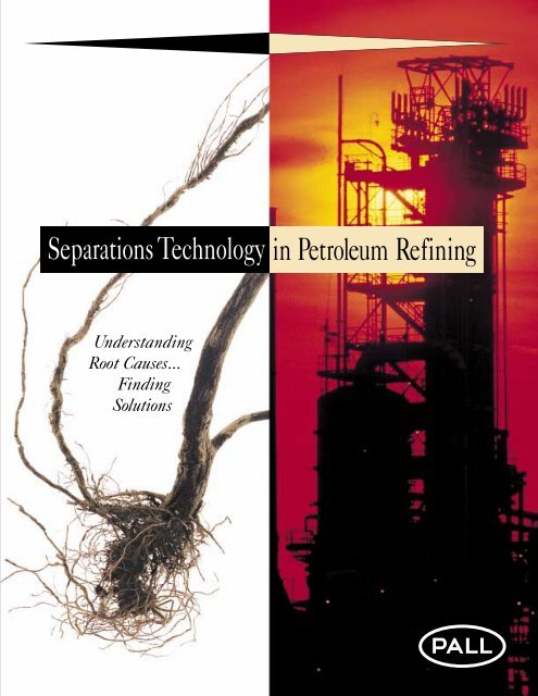
<strong>Separations</strong> <strong>Technology</strong> <strong>in</strong> <strong>Petroleum</strong> Ref<strong>in</strong><strong>in</strong>g<br />
Understand<strong>in</strong>g<br />
Root Causes...<br />
F<strong>in</strong>d<strong>in</strong>g<br />
Solutions
Search<strong>in</strong>g out root causes...<br />
then apply<strong>in</strong>g separations<br />
technology.<br />
We at <strong>Pall</strong> <strong>Corporation</strong> understand<br />
that your bottom l<strong>in</strong>e is more important<br />
to you than our product l<strong>in</strong>e. That’s why<br />
we don’t rush to provide quick product<br />
“fixes.” Instead, we address the root<br />
causes of problems faced by the petroleum<br />
ref<strong>in</strong><strong>in</strong>g <strong>in</strong>dustry. Then we put our<br />
decades of experience and thorough<br />
technological knowhow to work to design<br />
and implement long-last<strong>in</strong>g solutions.<br />
<strong>Pall</strong> <strong>Corporation</strong> ma<strong>in</strong>ta<strong>in</strong>s its position<br />
as the world leader <strong>in</strong> filtration and separations<br />
technology with a steady stream<br />
of <strong>in</strong>novative, high-quality products<br />
backed by unmatched service and support.<br />
We <strong>in</strong>vest heavily <strong>in</strong> R&D and<br />
technical service to provide the ref<strong>in</strong><strong>in</strong>g<br />
<strong>in</strong>dustry with exceptional returns on their<br />
<strong>in</strong>vestment.<br />
<strong>Pall</strong>’s filtration and separations solutions<br />
have been successfully applied <strong>in</strong><br />
ref<strong>in</strong>eries throughout the world, <strong>in</strong> consultation<br />
with our customers.<br />
2
Our specialized total process approach:<br />
•Reduces Lost Production<br />
•Reduces Unscheduled Downtime<br />
•Lowers Ma<strong>in</strong>tenance Costs<br />
•Lowers Energy Costs<br />
•Raises Product Yield and Conversion<br />
•Meets Environmental Standards<br />
<strong>Pall</strong> puts together high-quality filtration<br />
systems that meet the unique<br />
requirements of every ref<strong>in</strong>ery we serve.<br />
We design and manufacture virtually all<br />
of our media, elements, vessels, and fully<br />
<strong>in</strong>tegrated separations systems. By supply<strong>in</strong>g<br />
the broadest array of polymeric,<br />
<strong>in</strong>organic, metallic, and ceramic media<br />
available, <strong>Pall</strong> is able to select the optimal<br />
filter medium to meet specific process<br />
requirements.<br />
In rare cases where <strong>Pall</strong> does not have<br />
an appropriate product, we work with the<br />
customer to develop a new product that<br />
solves the problem. We are eager to take<br />
on any challenge and are committed to<br />
keep<strong>in</strong>g up with the evolv<strong>in</strong>g demands of<br />
the markets we serve.<br />
<strong>Pall</strong> delivers worldwide technological<br />
consultation and support through our<br />
Scientific and Laboratory Services<br />
Department (SLS), a network of about<br />
400 scientists and eng<strong>in</strong>eers experienced<br />
<strong>in</strong> <strong>in</strong>vestigat<strong>in</strong>g and solv<strong>in</strong>g the various<br />
and often complex problems encountered<br />
<strong>in</strong> fluid clarification and separation<br />
processes. In addition, a specialized<br />
group of scientists and eng<strong>in</strong>eers is solely<br />
dedicated to customers <strong>in</strong> the petroleum<br />
ref<strong>in</strong><strong>in</strong>g <strong>in</strong>dustry. <strong>Pall</strong> has more than 20<br />
state-of-the-art laboratories located<br />
throughout the United States, Europe,<br />
and Asia.<br />
All <strong>Pall</strong> manufactur<strong>in</strong>g facilities<br />
adhere to uniform manufactur<strong>in</strong>g procedures<br />
and have been granted International<br />
Standards Organization (ISO) certification<br />
to ISO 9001. This ensures that <strong>Pall</strong> filtration<br />
products and systems will perform<br />
exactly as specified, no matter where <strong>in</strong><br />
the world they are <strong>in</strong>stalled.<br />
Total Quality Management, root<br />
cause analysis, and the total process<br />
approach are the pr<strong>in</strong>ciples on which we<br />
base our success <strong>in</strong> the petroleum ref<strong>in</strong><strong>in</strong>g<br />
<strong>in</strong>dustry. We look forward to apply<strong>in</strong>g<br />
our pr<strong>in</strong>ciples, technology, and experience<br />
to help you achieve a higher level of<br />
process control and efficiency <strong>in</strong> your<br />
operations.<br />
SLS test facility.<br />
Contents<br />
Pages 9-14<br />
Separation of<br />
Solids from Liquids<br />
Pages 15-19<br />
Separation of<br />
Solids from Gases<br />
Pages 20-21<br />
Separation of Liquids and<br />
Solids from Gases<br />
Pages 22-23<br />
Separation of<br />
Liquids from Liquids<br />
3
Ref<strong>in</strong>ery Filtration<br />
Recommendations<br />
The charts below and the adjacent schematic represent<br />
typical flow systems with<strong>in</strong> the ref<strong>in</strong>ery. Systems are detailed<br />
with<strong>in</strong> the draw<strong>in</strong>g and <strong>in</strong>clude major filter locations/applications.<br />
The numbered items <strong>in</strong> each system co<strong>in</strong>cide with the<br />
recommended filter/separation application tables below.<br />
Application<br />
a<br />
Am<strong>in</strong>e<br />
Sweeten<strong>in</strong>g<br />
b<br />
Tail Gas<br />
Treat<strong>in</strong>g Unit<br />
c<br />
Aromatics<br />
d<br />
Catalyst<br />
Protection<br />
PALL PARTICULATE/BACKWASH FILTERS*<br />
Problem<br />
Liquid hydrocarbon<br />
and particulates cause<br />
foam<strong>in</strong>g and foul<strong>in</strong>g<br />
problems with<strong>in</strong> an<br />
am<strong>in</strong>e plant.<br />
Many tail gas units<br />
conta<strong>in</strong> an am<strong>in</strong>e<br />
unit.**<br />
Liquid hydrocarbon<br />
and particulates cause<br />
foam<strong>in</strong>g and foul<strong>in</strong>g<br />
problems.<br />
Solid particulates plug<br />
and deactivate catalyst<br />
bed (5-10 µm); water<br />
can deactivate some<br />
catalysts.<br />
Benefits<br />
PALL PARTICULATE FILTERS*<br />
Reduced am<strong>in</strong>e losses, foam<strong>in</strong>g,<br />
and flar<strong>in</strong>g; improved energy<br />
consumption; reduced ma<strong>in</strong>tenance,<br />
labor, and disposal costs.<br />
Same as Am<strong>in</strong>e Sweeten<strong>in</strong>g a<br />
Process similar to am<strong>in</strong>e;<br />
reduced solvent losses and foam<strong>in</strong>g;<br />
Improved energy consumption;<br />
reduced ma<strong>in</strong>tenance, labor, and<br />
disposal costs.<br />
Improved conversion efficiency<br />
and profitability; fewer catalyst<br />
changeouts; improved conversion/<br />
yield; lower ma<strong>in</strong>tenance, labor,<br />
and catalyst costs.<br />
Application<br />
g<br />
Am<strong>in</strong>e and<br />
Sulfur<br />
Recovery<br />
Unit<br />
h<br />
Ref<strong>in</strong>ery<br />
Fuel Gas<br />
i<br />
Hydrogen<br />
Compressor<br />
Protection<br />
Application<br />
j<br />
Catalyst<br />
Recovery<br />
from Gas<br />
Streams<br />
PALL LIQUID/GAS COALESCERS<br />
Problem Benefits<br />
Carried-over am<strong>in</strong>e contam<strong>in</strong>ates<br />
catalyst at the sulfur recovery unit.<br />
Carried-over hydrocarbon and<br />
treat<strong>in</strong>g chemicals <strong>in</strong>itiate foam<strong>in</strong>g<br />
<strong>in</strong> am<strong>in</strong>e contactor.<br />
Fuel gas composition changes<br />
rapidly, and conta<strong>in</strong>s condensable<br />
hydrocarbons; liquids and solids<br />
will foul, plug burners and combusters;<br />
low NOx burners very sensitive<br />
to plugg<strong>in</strong>g.<br />
Hydrogen composition changes<br />
rapidly and conta<strong>in</strong>s condensable<br />
hydrocarbons; liquids and solids<br />
will foul <strong>in</strong>ternals of compressors;<br />
must know composition of liquids<br />
be<strong>in</strong>g recovered by coalescer.<br />
PALL BLOWBACK FILTERS*<br />
Problem Benefits<br />
Catalyst f<strong>in</strong>es discharged <strong>in</strong>to flue<br />
or elutriation gas caus<strong>in</strong>g catalyst<br />
losses, opacity problems, ma<strong>in</strong>tenance<br />
problems with downstream<br />
equipment. Particularly a problem<br />
where catalyst is cont<strong>in</strong>uously<br />
regenerated.<br />
PALL LIQUID/LIQUID COALESCERS<br />
Fewer catalyst changeouts;<br />
improved sulfur conversion,<br />
less equipment foul<strong>in</strong>g.<br />
Reduced am<strong>in</strong>e losses,<br />
foam<strong>in</strong>g and flar<strong>in</strong>g.<br />
Improved reliability;<br />
lower ma<strong>in</strong>tenance costs;<br />
improved burn<strong>in</strong>g<br />
efficiency.<br />
Improved reliability;<br />
lower ma<strong>in</strong>tenance costs;<br />
improved efficency.<br />
Fewer catalyst losses;<br />
less ma<strong>in</strong>tenance on<br />
downstream equipment;<br />
compliance with environmental<br />
standards.<br />
e<br />
F<strong>in</strong>al<br />
Product<br />
Filtration<br />
f<br />
Fluid<br />
Catalytic<br />
Crack<strong>in</strong>g Unit<br />
Slurry Oil<br />
Ref<strong>in</strong>ery f<strong>in</strong>al products<br />
conta<strong>in</strong> particulates<br />
and water.<br />
PALL BACKWASH FILTERS*<br />
Catalyst f<strong>in</strong>es reduce<br />
value of slurry oil.<br />
Improved product quality; fewer<br />
reprocess<strong>in</strong>g and contam<strong>in</strong>ation<br />
costs; lower ma<strong>in</strong>tenance and<br />
disposal costs.<br />
Improved product quality and<br />
revenue; less downstream<br />
equipment ma<strong>in</strong>tenance.<br />
*In applications where different options are listed, <strong>Pall</strong> <strong>Corporation</strong> will assist project<br />
eng<strong>in</strong>eers <strong>in</strong> determ<strong>in</strong><strong>in</strong>g the optimum filtration option.<br />
**Note: Many TGTU’s conta<strong>in</strong> another am<strong>in</strong>e plant to remove residual H 2 S.<br />
Application<br />
k<br />
F<strong>in</strong>al<br />
Product<br />
Filtration<br />
l<br />
Catalyst<br />
Protection<br />
m<br />
Treat<strong>in</strong>g<br />
Problem Benefits<br />
Ref<strong>in</strong>ery f<strong>in</strong>al products conta<strong>in</strong><br />
particles and water.<br />
Solid particulates plug and deactivate<br />
catalyst bed<br />
(5-10 µm); water can<br />
deactivate some catalysts.<br />
Caustic or am<strong>in</strong>e carries over<br />
<strong>in</strong>to product stream caus<strong>in</strong>g<br />
off-specification product;<br />
carried-over caustic can form<br />
a precipitate downstream<br />
result<strong>in</strong>g <strong>in</strong> equipment foul<strong>in</strong>g.<br />
Improved product quality;<br />
fewer reprocess<strong>in</strong>g and<br />
contam<strong>in</strong>ation costs;<br />
lower ma<strong>in</strong>tenance and<br />
disposal costs.<br />
Improved conversion<br />
efficiency and profitability;<br />
fewer catalyst changeouts;<br />
lower ma<strong>in</strong>tenance, labor,<br />
and catalyst costs.<br />
Improved profitability;<br />
lower reprocess<strong>in</strong>g costs;<br />
reduced ma<strong>in</strong>tenance and<br />
labor costs.<br />
4
▼<br />
Search<strong>in</strong>g Out<br />
Root Causes . . .<br />
Then Apply<strong>in</strong>g<br />
<strong>Separations</strong><br />
<strong>Technology</strong><br />
To review ref<strong>in</strong>ery filtration applications schematic, open here.<br />
7
Ref<strong>in</strong>ery Filtration Applications<br />
H 2<br />
Gas<br />
HYDROGEN<br />
PRODUCTION<br />
Fuel Gas<br />
SULFUR<br />
RECOVERY<br />
Acid Gas<br />
LPG<br />
Naphtha<br />
HYDROTREATING<br />
Sour Gas<br />
AMINE<br />
Crude Oil<br />
Fuel Gas<br />
Atmosphere Distillation<br />
Kerosene & Middle Distillates<br />
Fuel Gas<br />
Gas Oil<br />
ISOMERIZATION<br />
DEHYDROGENATION<br />
Fuel<br />
Gas<br />
HYDROTREATING<br />
H 2<br />
HYDROTREATING<br />
Sour Gas<br />
Fuel<br />
Gas<br />
Sour Gas<br />
Off<br />
Gas<br />
Sour Gas<br />
FLUID<br />
CATALYTIC<br />
CRACKING<br />
Flue<br />
Gas<br />
Fuel Gas<br />
Vacuum<br />
Distillation<br />
To FCC<br />
Fuel Gas<br />
Coker Gas Oil<br />
COKER<br />
5
Sulfur<br />
TAIL GAS<br />
TREATING<br />
Stack<br />
Ref<strong>in</strong>ery Fuel<br />
Gas<br />
ISOMERIZATION<br />
AMINE<br />
LPG<br />
Gasol<strong>in</strong>e<br />
Fuel Gas<br />
CATALYTIC<br />
REFORMING<br />
H 2<br />
AROMATICS<br />
EXTRACTION<br />
Benzene, Toluene,<br />
Xylene<br />
Gasol<strong>in</strong>e<br />
Solvents<br />
HYDROTREATING<br />
CAUSTIC<br />
TREATING<br />
Fuel Gas<br />
MTBE<br />
Benzene<br />
Jet Fuel<br />
Kerosene<br />
Petrochemical<br />
Feedstock<br />
Gasol<strong>in</strong>e<br />
Higher Olef<strong>in</strong>s<br />
Gasol<strong>in</strong>e<br />
MeOH<br />
ALKYLATION<br />
Gasol<strong>in</strong>e<br />
Gasol<strong>in</strong>e<br />
H 2<br />
Slurry Oil<br />
HYDROCRACKING<br />
Jet Fuel, Diesel<br />
Fuel Gas<br />
Coke<br />
6
<strong>Pall</strong> Products —The Ref<strong>in</strong>er’s Optimum Choice<br />
With a broad l<strong>in</strong>e of filtration and separation<br />
products, <strong>Pall</strong> can help ref<strong>in</strong>eries<br />
improve fluid quality and <strong>in</strong>crease profitability<br />
by optimiz<strong>in</strong>g the performance of<br />
process<strong>in</strong>g equipment. Many of <strong>Pall</strong>’s<br />
products were developed specifically for<br />
this <strong>in</strong>dustry, <strong>in</strong> collaboration with our customers.<br />
Our close relationship with ref<strong>in</strong>ers<br />
and process licensors has helped <strong>Pall</strong> to<br />
understand their current and future needs.<br />
Our awareness of and dedication to this<br />
market have fueled our product development<br />
programs and sharpened our technical<br />
and scientific skills. In turn, <strong>Pall</strong> is able<br />
to offer expertise and a flow of new products<br />
that help maximize the efficiencies<br />
and economics of a ref<strong>in</strong>er. <strong>Pall</strong>’s expertise<br />
and products are categorized by the follow<strong>in</strong>g<br />
important operations:<br />
SEPARATION OF<br />
SOLIDS FROM<br />
LIQUIDS<br />
SEPARATION OF<br />
LIQUIDS AND SOLIDS<br />
FROM GASES<br />
SEPARATION OF<br />
SOLIDS FROM<br />
GASES<br />
SEPARATION OF<br />
LIQUIDS FROM<br />
LIQUIDS<br />
•Separation of Solids from Liquids<br />
•Separation of Solids from Gases<br />
•Separation of Liquids and Solids<br />
from Gases<br />
•Separation of Liquids from Liquids<br />
At the heart of every filtration and<br />
separation system is the medium which<br />
performs the separation. <strong>Pall</strong> manufactures<br />
21 dist<strong>in</strong>ct families of media, provid<strong>in</strong>g<br />
over 150 grades of polymeric, <strong>in</strong>organic,<br />
metal, and ceramic filter products<br />
and phase separation devices. This<br />
means <strong>Pall</strong> can supply the highest quality<br />
medium for ref<strong>in</strong>ery applications —<br />
without compromise.<br />
The technology we offer for these<br />
ref<strong>in</strong>ery operations is identified <strong>in</strong> the<br />
four sections of this reference guide.<br />
Refer to the appropriate section for<br />
details concern<strong>in</strong>g your application.<br />
<strong>Pall</strong> filter media.<br />
8
SEPARATION OF SOLIDS FROM LIQUIDS<br />
A variety of filtration methods can be<br />
selected for specific solid/liquid separations<br />
applications <strong>in</strong> ref<strong>in</strong>eries, due to the<br />
differ<strong>in</strong>g concentration of solids <strong>in</strong> liquid<br />
streams. For high solids load<strong>in</strong>g, a backwash<br />
system may be the optimum filtration<br />
solution, while disposable filter<br />
media would be used for fairly low solidsload<strong>in</strong>g<br />
applications. In some cases,<br />
removal of solids may require a comb<strong>in</strong>ation<br />
of backwash followed by a disposable<br />
filter for polish<strong>in</strong>g. Whichever<br />
filtration product or comb<strong>in</strong>ation provides<br />
the best overall performance and economy,<br />
<strong>Pall</strong> has the capability of provid<strong>in</strong>g<br />
you with the solution.<br />
<strong>Pall</strong> orig<strong>in</strong>ally developed backwash<br />
technology <strong>in</strong> the 1960’s <strong>in</strong> response to<br />
the needs of hydrogenated chemical producers.<br />
This technology started to ga<strong>in</strong><br />
acceptance <strong>in</strong> ref<strong>in</strong>eries <strong>in</strong> the late 1980’s<br />
when ref<strong>in</strong>ers needed to upgrade the<br />
value of slurry oil <strong>in</strong> Fluid Catalytic<br />
Crack<strong>in</strong>g units by remov<strong>in</strong>g catalyst<br />
f<strong>in</strong>es. This cont<strong>in</strong>ually evolv<strong>in</strong>g backwash<br />
technology is now used <strong>in</strong> other<br />
ref<strong>in</strong><strong>in</strong>g processes for the purpose of<br />
extend<strong>in</strong>g the life of catalyst and improv<strong>in</strong>g<br />
conversion <strong>in</strong> hydrotreaters and<br />
hydrocrackers. <strong>Pall</strong> Backwash Systems<br />
offer significant benefits over conventional<br />
wedgewire systems that are used to<br />
protect catalyst beds.<br />
<strong>Pall</strong> Products<br />
<strong>Pall</strong> Backwash Filter<br />
Media Selection<br />
•PSS S<strong>in</strong>tered Powder Medium<br />
•<strong>Pall</strong> PMF Metal Fiber Filters<br />
•Rigimesh S<strong>in</strong>tered Woven Wire Medium<br />
•<strong>Pall</strong> ProSep Backwashable Filters<br />
•<strong>Pall</strong> Septra Backwashable Filters<br />
<strong>Pall</strong> Disposable<br />
Filter Selection<br />
•<strong>Pall</strong> Profile II Depth Filters<br />
•<strong>Pall</strong> Ultipleat Profile Depth Filters<br />
•<strong>Pall</strong> Pleated Filters with<br />
Epocel Medium<br />
Ultipor GF Plus Medium<br />
HDC II Medium<br />
•<strong>Pall</strong> Profile Bag Filters<br />
<strong>Pall</strong> Backwash Systems have extremely low operat<strong>in</strong>g and ma<strong>in</strong>tenance costs as compared with other<br />
technologies such as electrostatic separators and hydrocyclones.<br />
9
<strong>Pall</strong> Backwash Systems<br />
A backwash system is designed to<br />
remove and/or collect suspended solids<br />
from a liquid process stream while periodically<br />
regenerat<strong>in</strong>g itself. A porous filter<br />
medium with suitable pore size will<br />
efficiently collect solids on its surface,<br />
where they form a permeable cake.<br />
Dur<strong>in</strong>g backwash, a reverse flow will be<br />
<strong>in</strong>itiated at a predeterm<strong>in</strong>ed filter pressure<br />
drop and/or time <strong>in</strong>terval, discharg<strong>in</strong>g<br />
the collected solids to recovery. The<br />
filter will then be returned to full forward<br />
flow. Its pressure drop just after backwash<br />
will rema<strong>in</strong> essentially constant<br />
through backwash cycles.<br />
While vessel design, tubesheet assembly,<br />
pip<strong>in</strong>g, <strong>in</strong>strumentation, and valve<br />
selection all play an important role <strong>in</strong> their<br />
smooth function<strong>in</strong>g, backwash capability<br />
is the central feature of <strong>Pall</strong> Backwash<br />
Systems. With a variety of porous filter<br />
media, both metallic and nonmetallic, and<br />
backwash techniques, <strong>Pall</strong>’s Backwash<br />
Systems are designed and optimized for<br />
specific ref<strong>in</strong>ery applications.<br />
For example, many hydrotreaters use<br />
backwash filters to remove solids from<br />
the feed and protect the catalyst bed. In<br />
the past, wedgewire media were used <strong>in</strong><br />
these systems. These media only provide<br />
about three to five percent void volume<br />
<strong>in</strong> this application. Replac<strong>in</strong>g the<br />
wedgewire elements <strong>in</strong> the filter vessel<br />
with <strong>Pall</strong> Rigimesh elements provides<br />
approximately seven times higher void<br />
volume and twice the filter area. An<br />
upgrade should be based on a need for<br />
f<strong>in</strong>er filtration and higher throughputs<br />
prior to backwash cycles.<br />
Retrofits are possible and new <strong>Pall</strong><br />
systems are be<strong>in</strong>g employed. The <strong>Pall</strong><br />
Backwash System provides substantial<br />
benefits, <strong>in</strong>clud<strong>in</strong>g:<br />
•Improved Effluent Quality<br />
•Higher Throughputs<br />
•Lower ∆P<br />
•Fewer Clean<strong>in</strong>gs<br />
•Lower Utility Costs<br />
•Lower Product Recycle<br />
(reduced by as much as five-fold)<br />
•Payback <strong>in</strong> Less Than 1 Year<br />
•Extremely Low Cost of Operation<br />
vs. Wedgewire Systems<br />
Backwash Systems Comparison<br />
Efficiency<br />
Solids-Load<strong>in</strong>g<br />
Capability<br />
Operat<strong>in</strong>g and<br />
Ma<strong>in</strong>tenance Cost<br />
Backwash Fluid<br />
Requirement vs.<br />
Throughput<br />
Sensitivity to<br />
Flow Rate Change<br />
Temperature Range<br />
<strong>Pall</strong> Backwash<br />
System<br />
High<br />
High<br />
Very Low<br />
10%<br />
Very High<br />
Low<br />
<strong>Pall</strong> Rigimesh Medium versus Wedgewire<br />
<strong>Pall</strong> Rigimesh medium—approximate void volume =30%.<br />
Typical wedgewire element—approximate void volume =4%.<br />
Wedgewire Hydrocylones Sand Beds<br />
Low<br />
Low<br />
Very High<br />
2-20%<br />
None<br />
High<br />
Medium<br />
High<br />
Low<br />
6%<br />
None<br />
Medium<br />
Low<br />
High<br />
Low<br />
1-2%<br />
None<br />
High<br />
Reliability and Safety<br />
of Operations<br />
High<br />
Medium<br />
Low<br />
Medium<br />
Medium<br />
10
Ref<strong>in</strong>eries receive high return on <strong>in</strong>vestment after <strong>in</strong>stall<strong>in</strong>g <strong>Pall</strong> backwash filters to protect catalyst beds and to remove catalyst f<strong>in</strong>es from FCC slurry oil.<br />
Gas-Assist Backwash Method<br />
The gas-assist method is used when<br />
process flow rates are high, or, cont<strong>in</strong>uous,<br />
un<strong>in</strong>terrupted flow is required. For<br />
backwash, one vessel is isolated and the<br />
downstream side of the vessel is pressurized<br />
with a controlled quantity of filtered<br />
air or other suitable gas. The vessel dra<strong>in</strong><br />
port is rapidly opened, result<strong>in</strong>g <strong>in</strong> a<br />
hydraulic pulse that “bumps” the collected<br />
solids from the filter surface. Forward<br />
flow is restored to this vessel, and the<br />
rema<strong>in</strong><strong>in</strong>g filter vessels are backwashed<br />
sequentially.<br />
Dur<strong>in</strong>g gas-assist backwash, the<br />
expand<strong>in</strong>g gas bubble forces the liquid<br />
through the elements <strong>in</strong> the reverse<br />
direction (<strong>in</strong>side-out) at a velocity as high<br />
as seven times the normal forward flow<br />
velocity. This effectively dislodges the<br />
accumulated cake from the elements,<br />
while significantly reduc<strong>in</strong>g the volume<br />
of liquid required. Thus, the concentration<br />
of the solids discharge is high.<br />
Comb<strong>in</strong><strong>in</strong>g the gas-assist backwash<br />
with the high dirt-hold<strong>in</strong>g capacity of<br />
<strong>Pall</strong>’s backwash media results <strong>in</strong> long<br />
cycle times between backwash<strong>in</strong>g.<br />
Benefits of <strong>Pall</strong><br />
Backwash Systems and<br />
Gas-Assist Backwash<br />
•Longer Catalyst Life<br />
•Reduced Incidence of “Off-Spec”<br />
Product<br />
•Low Reprocess<strong>in</strong>g and/or Disposal<br />
Costs Due to Low Volume of<br />
Backwash Fluid<br />
•Low Ma<strong>in</strong>tenance Cost for Valves and<br />
Control Equipment<br />
•Infrequent “Out-of-Vessel” Element<br />
Clean<strong>in</strong>g<br />
<strong>Pall</strong> Backwash System<br />
Process<br />
Out<br />
Process<br />
In<br />
Backwash<br />
Gas In<br />
Solids Recovery<br />
•One or More Vessels<br />
•Isolate One Vessel for Backwash<br />
•A Compressed Volume of Gas Provides<br />
a High-Velocity Reverse Flow of<br />
Liquid Rema<strong>in</strong><strong>in</strong>g <strong>in</strong> Vessel<br />
11
<strong>Pall</strong> Metallic Backwash Filter Selection<br />
Porous Metal PSS Filters<br />
Manufactured of s<strong>in</strong>tered sta<strong>in</strong>less<br />
steel powder, the PSS “S” medium offers<br />
exceptionally uniform permeability, and<br />
absolute removal efficiencies.<br />
These elements are seamless <strong>in</strong> construction<br />
with very high void volume (up<br />
to 60% <strong>in</strong> some grades). This provides<br />
very high dirt-hold<strong>in</strong>g capacity and low<br />
pressure loss, especially <strong>in</strong> very f<strong>in</strong>e<br />
grades, which permit design at high flux<br />
to help reduce capital costs.<br />
In addition to the standard product<br />
made from 316L sta<strong>in</strong>less steel, we supply<br />
PSS medium <strong>in</strong> Inconel, nickel, nickel<br />
molybdenum, and alum<strong>in</strong>ide alloys.<br />
PMF Metal Fiber Filters<br />
PMF filters are manufactured of f<strong>in</strong>ediameter<br />
316L sta<strong>in</strong>less steel fibers that<br />
are s<strong>in</strong>tered at their po<strong>in</strong>ts of contact to<br />
produce a uniform, strong, tapered-pore<br />
medium with exceptionally high dirthold<strong>in</strong>g<br />
capacity while one or more <strong>in</strong>ner<br />
layers provide absolute-rated filtration.<br />
Rigimesh Sta<strong>in</strong>less Steel<br />
Woven Wire Mesh Filters<br />
<strong>Pall</strong>’s patented process permits the<br />
use of f<strong>in</strong>er-diameter wires <strong>in</strong> the manufacture<br />
of the Rigimesh sta<strong>in</strong>less steel<br />
medium. This results <strong>in</strong> low pressure<br />
drop, more pores per unit area, and better<br />
dirt-hold<strong>in</strong>g capacity than that of any<br />
other woven metal filter. The medium is<br />
s<strong>in</strong>tered for superior tensile, yield, shear,<br />
and fatigue strength. Rigimesh ma<strong>in</strong>ta<strong>in</strong>s<br />
a uniform pore size and exhibits no<br />
media migration, even under high temperature<br />
and pressure conditions.<br />
<strong>Pall</strong> Nonmetallic Backwash Filter Selection<br />
12<br />
ProSep Filters<br />
<strong>Pall</strong> ProSep filters are manufactured of<br />
polyolef<strong>in</strong> or polyaramid fiber, both of<br />
which provide outstand<strong>in</strong>g temperature<br />
and chemical compatibility. These filters<br />
have an outer (upstream) section <strong>in</strong> which<br />
fiber diameter and pore size decrease gradually<br />
to the element’s <strong>in</strong>nermost layer<br />
where the pore diameter is constant.<br />
Designed for use with or without a precoat,<br />
beta-rated ProSep filters are the appropriate<br />
choice <strong>in</strong> applications <strong>in</strong> which the process<br />
fluids have a high solids content.<br />
Septra Filters<br />
Septra filters <strong>in</strong>corporate a pleated,<br />
high-area absolute-rated polymeric medium<br />
<strong>in</strong> a rugged element construction<br />
designed for operation (without use of a<br />
precoat) <strong>in</strong> automated, clean-<strong>in</strong>-place<br />
fluid/solid separation systems. The higharea<br />
filter medium is a nonwoven construction<br />
that is available with polyolef<strong>in</strong>,<br />
polyaramid, or fiberglass fibers to suit<br />
operation up to 500°F (260°C).
<strong>Pall</strong> Disposable Filters<br />
When the solids concentration is relatively<br />
low (< 5 to 10 ppm), <strong>Pall</strong> disposable<br />
filters will efficiently and<br />
economically remove solids from liquid<br />
streams. <strong>Pall</strong> filters are used to remove<br />
solids from f<strong>in</strong>ished ref<strong>in</strong>ery products and<br />
from process<strong>in</strong>g fluids such as am<strong>in</strong>es,<br />
glycol, and sulfolane. <strong>Pall</strong> filters are characterized<br />
by high dirt-hold<strong>in</strong>g capacity,<br />
and lot-to-lot uniformity. They provide<br />
long service life and improved protection<br />
for equipment and personnel. <strong>Pall</strong> filter<br />
elements are designed to prevent both<br />
unload<strong>in</strong>g of trapped particles and media<br />
migration. They are self-align<strong>in</strong>g <strong>in</strong> <strong>Pall</strong><br />
filter vessels, with positive seal<strong>in</strong>g to<br />
elim<strong>in</strong>ate fluid bypass.<br />
<strong>Pall</strong> disposable filters are designed<br />
and manufactured for long, effective,<br />
trouble-free service life. Their advantages<br />
<strong>in</strong>clude:<br />
•Pore Size Uniformity for Full<br />
Utilization of the Filter Surface<br />
•Strength and Durability to Withstand<br />
the Chang<strong>in</strong>g Process Operations<br />
•Chemical and Thermal Compatibility<br />
with Process Conditions to Ensure<br />
Long Life<br />
• Absolute Rat<strong>in</strong>g* for Reliable, Replicable<br />
Performance, Backed by Documented<br />
Performance Data<br />
* An “absolute rat<strong>in</strong>g” is def<strong>in</strong>ed as B x =5000 as measured<br />
utiliz<strong>in</strong>g widely accepted modified OSU F-2 test.<br />
Comparison of Performance of Profile II<br />
Filters and Competitive Depth Filters<br />
Filtration Beta Ratio Comparison<br />
10000<br />
5000<br />
2000<br />
1000<br />
500<br />
200<br />
100<br />
50<br />
20<br />
10<br />
5<br />
2<br />
1<br />
Filtration Ratio Beta<br />
0.5<br />
1<br />
2<br />
4<br />
10<br />
25<br />
50<br />
Particle Size<br />
(µm)<br />
Profile II (P200)<br />
20 µm Absolute<br />
ß 20 = 5000<br />
NA<br />
NA<br />
99.98%<br />
>99.98%<br />
Filter Brand<br />
W1<br />
Wound Filter<br />
1 µm Nom<strong>in</strong>al<br />
ß 1 = 1<br />
Percent Removal Efficiency<br />
NA<br />
NA<br />
<strong>Pall</strong> Disposable Filter Selection<br />
Profile II Filters<br />
Profile II is a polymeric depth-type<br />
medium produced by a patented process<br />
that allows an upstream cont<strong>in</strong>uously<br />
graded section and a downstream<br />
absolute-rated section <strong>in</strong> a s<strong>in</strong>gle<br />
element.<br />
Ultipleat Profile Filters<br />
The unique crescent-shaped construction<br />
of the Ultipleat Profile filter<br />
element provides longer life than many<br />
pleated polypropylene media. Optimized<br />
for the removal of gels and other viscous<br />
fluids, the Ultipleat Profile filter provides<br />
excellent chemical compatibility with low<br />
extractables. Ultipleat Profile filter<br />
elements are the appropriate choice for<br />
a wide range of applications <strong>in</strong> the<br />
ref<strong>in</strong><strong>in</strong>g <strong>in</strong>dustry.<br />
Epocel Filters<br />
Epocel cartridges have a pleated,<br />
high-area construction which provides<br />
long service life and consistent production.<br />
Constructed of epoxy-res<strong>in</strong>impregnated<br />
cellulose, this fixed-pore<br />
construction elim<strong>in</strong>ates unload<strong>in</strong>g and<br />
media migration. Epocel cartridges provide<br />
a broad range of chemical compatibility<br />
and are recommended for the<br />
clarification of a wide range of fluids<br />
and gases.<br />
Ultipor GF Plus Filters<br />
The Ultipor GF Plus medium consists<br />
of res<strong>in</strong>-bonded glass fibers supported by<br />
upstream and downstream polymeric substrates.<br />
This unique construction provides<br />
a strongly bonded, migration-free, highdirt-capacity<br />
medium.<br />
HDC II Filters<br />
The HDC II medium consists of<br />
multiple layers of cont<strong>in</strong>uous fiber, nonwoven<br />
polypropylene pleated together,<br />
with no b<strong>in</strong>ders or extraneous material.<br />
HDC II cartridges have an extremely<br />
high dirt capacity, due to their taperedpore<br />
construction, and a wide range of<br />
chemical compatibility.<br />
Profile Bag Filters<br />
High-efficiency, beta-rated Profile bag<br />
filters are suitable for a wide variety of<br />
applications. They conta<strong>in</strong> an outer<br />
(downstream) section that has a constant<br />
pore diameter to provide consistent, betarated<br />
filtration. The <strong>in</strong>ner (upstream) section<br />
cont<strong>in</strong>uously <strong>in</strong>creases <strong>in</strong> pore diameter<br />
to provide effective prefiltration.<br />
The tapered-pore structure and depth of<br />
the medium comb<strong>in</strong>e to provide long<br />
service life.<br />
14
SEPARATION OF SOLIDS FROM GASES<br />
Deal<strong>in</strong>g with aggressive environments,<br />
extreme temperatures, and high<br />
contam<strong>in</strong>ant concentrations, <strong>Pall</strong> has cont<strong>in</strong>ually<br />
developed state-of-the-art technology<br />
for solid/gas separation. To<br />
efficiently separate solid particulates from<br />
gas streams, <strong>Pall</strong> has worked with both<br />
ref<strong>in</strong>ers and process licensors to develop<br />
blowback systems. A filter medium with<br />
sufficiently small pores is selected for this<br />
application. Solids form a permeable cake<br />
on the filter’s surface that is dislodged at<br />
a predeterm<strong>in</strong>ed pressure drop (a function<br />
of cake thickness and compressibility)<br />
by <strong>in</strong>itiat<strong>in</strong>g a reverse pulse<br />
(blowback). The dislodged solids are<br />
purged from the filter system, where<br />
they may be returned directly to the<br />
process for reuse, or removed from the<br />
process stream and sent to a storage or<br />
collection unit. The filter is then<br />
returned to full forward flow and to an<br />
<strong>in</strong>itial pressure drop that rema<strong>in</strong>s essentially<br />
constant through repeated blowback<br />
cycles.<br />
<strong>Pall</strong> Blowback Systems conta<strong>in</strong> either<br />
porous metal or ceramic filters. The<br />
superior capabilities of <strong>Pall</strong> Blowback<br />
Systems, as opposed to other types of<br />
equipment, are shown <strong>in</strong> chart at right.<br />
<strong>Pall</strong> Products<br />
<strong>Pall</strong> Blowback Filter<br />
Media Selection<br />
•<strong>Pall</strong> PMF Metal Fiber Filters<br />
•PSS S<strong>in</strong>tered Powder Filters<br />
•Rigimesh S<strong>in</strong>tered Woven Wire Medium<br />
•Vitrosep Blowback Filters<br />
•Vitropore Ceramic Filter Candles<br />
<strong>Pall</strong> Gas Particle<br />
Disposable Filter Selection<br />
•<strong>Pall</strong> Pleated Filters with<br />
Ultipor GF Plus Medium<br />
HDC II Medium<br />
Epocel Medium<br />
•<strong>Pall</strong> Ultipleat Profile Filters<br />
•<strong>Pall</strong> Profile II Depth Filter<br />
Blowback Systems Comparison<br />
Efficiency of Solid Separation<br />
from Gas Stream<br />
Separation Efficiency Varies<br />
with Solids Load<strong>in</strong>g<br />
Blowback<br />
<strong>Pall</strong> Filters Cyclone Baghouse Scrubber<br />
>99.99%<br />
No<br />
98%<br />
Yes<br />
<strong>Pall</strong> blowback filter system <strong>in</strong> operation.<br />
99.9%<br />
No<br />
99%<br />
Yes<br />
Electrostatic<br />
Precipitator<br />
99%<br />
Yes<br />
Relative Operat<strong>in</strong>g<br />
Pressure Drop<br />
Medium<br />
Medium<br />
Medium<br />
High<br />
Low<br />
Maximum Operat<strong>in</strong>g<br />
Temperature<br />
1650°F<br />
>2000°F<br />
450°F<br />
450°F<br />
900°F<br />
Sensitivity to Changes<br />
<strong>in</strong> Flow Rate<br />
Insensitive<br />
Very Sensitive<br />
Some Sensitivity<br />
Very Sensitive<br />
Very Sensitive<br />
Precool<strong>in</strong>g Required Upstream of<br />
Solid Separation Device<br />
No<br />
No<br />
Yes<br />
Yes<br />
Yes<br />
Solids-Load<strong>in</strong>g Reduction Prior<br />
to F<strong>in</strong>al Separation Required<br />
No<br />
No<br />
Yes<br />
Yes<br />
Yes<br />
Reliability and Safety of<br />
Operation<br />
High<br />
High<br />
Low<br />
Medium<br />
Medium<br />
15
<strong>Pall</strong> Blowback Filter Selection<br />
Porous Metal PSS Filters<br />
Manufactured of s<strong>in</strong>tered sta<strong>in</strong>less<br />
steel powder, the PSS “S” medium offers<br />
exceptionally uniform permeability, and<br />
absolute removal efficiencies.<br />
These elements are seamless <strong>in</strong> construction<br />
with very high void volume (up<br />
to 60% <strong>in</strong> some grades). This provides<br />
very high dirt-hold<strong>in</strong>g capacity and low<br />
pressure loss, especially <strong>in</strong> very f<strong>in</strong>e<br />
grades, which permit design at high flux<br />
to help reduce capital costs.<br />
In addition to the standard product<br />
made from 316L sta<strong>in</strong>less steel, we supply<br />
PSS medium <strong>in</strong> Inconel, nickel, nickel<br />
molybdenum, and alum<strong>in</strong>ide alloys.<br />
PMF Metal Fiber Filters<br />
PMF filters are manufactured of f<strong>in</strong>ediameter<br />
316L sta<strong>in</strong>less steel fibers that<br />
are s<strong>in</strong>tered at their po<strong>in</strong>ts of contact to<br />
produce a uniform, strong, tapered-pore<br />
medium with exceptionally high dirthold<strong>in</strong>g<br />
capacity while one or more <strong>in</strong>ner<br />
layers provide absolute-rated filtration.<br />
Rigimesh Sta<strong>in</strong>less Steel<br />
Woven Wire Mesh Filters<br />
<strong>Pall</strong>’s patented process permits the<br />
use of f<strong>in</strong>er-diameter wires <strong>in</strong> the manufacture<br />
of the Rigimesh sta<strong>in</strong>less steel<br />
medium. This results <strong>in</strong> low pressure<br />
drop, more pores per unit area, and better<br />
dirt-hold<strong>in</strong>g capacity than that of any<br />
other woven metal filter. The medium is<br />
s<strong>in</strong>tered for superior tensile, yield, shear,<br />
and fatigue strength. Rigimesh ma<strong>in</strong>ta<strong>in</strong>s<br />
a uniform pore size and exhibits no<br />
media migration, even under high temperature<br />
and pressure conditions.<br />
Vitrosep Blowback Filters<br />
The rugged construction of the<br />
Vitrosep clean-<strong>in</strong>-place blowback filter<br />
allows jet pulse clean<strong>in</strong>g and operation at<br />
high flux. This reduces the system footpr<strong>in</strong>t<br />
and lowers <strong>in</strong>stalled cost of the<br />
equipment. Equipped with a one micron<br />
rated Teflon coated fiberglass medium,<br />
Vitrosep is constructed of a sta<strong>in</strong>less steel<br />
core, outer mesh wrap, and end caps.<br />
Vitropore Ceramic Filter Candles<br />
This rigid, highly efficient silicon carbide<br />
medium possesses high temperature<br />
and excellent corrosion resistance for gas<br />
clarification and solids recovery.<br />
The ability of every <strong>Pall</strong> Vitropore<br />
candle to withstand corrosion and fracture<br />
at high temperatures (to 1000°C) proves it<br />
has the necessary characteristics to clean<br />
up hot gases. At temperatures above<br />
650ºC, Vitropore candles are more resistant<br />
to corrosion than most metal filters.<br />
16
<strong>Pall</strong> Gas Particle Disposable Filter Selection<br />
HDC II Filters<br />
The HDC II medium consists of<br />
multiple layers of cont<strong>in</strong>uous fiber, nonwoven<br />
polypropylene pleated together,<br />
with no b<strong>in</strong>ders or extraneous material.<br />
HDC II cartridges have an extremely<br />
high dirt capacity, due to their taperedpore<br />
construction, and a wide range of<br />
chemical compatibility.<br />
Epocel Filters<br />
Epocel cartridges have a pleated,<br />
high-area construction which provides<br />
long service life and consistent production.<br />
Constructed of epoxy-res<strong>in</strong>impregnated<br />
cellulose, this fixed-pore<br />
construction elim<strong>in</strong>ates unload<strong>in</strong>g and<br />
media migration. Epocel cartridges provide<br />
a broad range of chemical compatibility<br />
and are recommended for the<br />
clarification of a wide range of fluids<br />
and gases.<br />
Ultipor GF Plus Filters<br />
The Ultipor GF Plus medium consists<br />
of res<strong>in</strong>-bonded glass fibers supported by<br />
upstream and downstream polymeric substrates.<br />
This unique construction provides<br />
a strongly bonded, migration-free, highdirt-capacity<br />
medium.<br />
Ultipleat Profile Filters<br />
The unique crescent-shaped construction<br />
of the Ultipleat Profile filter element<br />
provides longer life than many<br />
pleated polypropylene media. Ultipleat<br />
Profile filter elements are the appropriate<br />
choice for a wide range of applications <strong>in</strong><br />
the ref<strong>in</strong><strong>in</strong>g <strong>in</strong>dustry.<br />
Profile II Filters<br />
Profile II is a polymeric depth-type<br />
medium produced by a patented process<br />
that allows an upstream cont<strong>in</strong>uously<br />
graded section and a downstream<br />
absolute-rated section <strong>in</strong> a s<strong>in</strong>gle<br />
element.<br />
17
Jet Pulse Blowback Method<br />
The jet pulse blowback method is<br />
cost effective because it elim<strong>in</strong>ates the<br />
need for large vessel isolation valves. Full<br />
forward flow is ma<strong>in</strong>ta<strong>in</strong>ed at all times.<br />
Groups of elements are blown back<br />
sequentially by direct<strong>in</strong>g a high-pressure<br />
pulse of gas <strong>in</strong>to the throat of each element.<br />
The pulses last between 0.1 and<br />
1.0 second, at two to three times the<br />
process pressure. Dur<strong>in</strong>g this period, the<br />
flow to the elements be<strong>in</strong>g cleaned is<br />
reversed momentarily by a high-pressure<br />
jet pulse. The shock wave set up by the<br />
reverse pulse, enhanced by the venturi <strong>in</strong><br />
the element throat, effectively removes<br />
the accumulated cake from the elements.<br />
<strong>Pall</strong> Blowback System<br />
Process In<br />
Process Out<br />
Blowback Gas<br />
Solids Recovery<br />
•One or More Vessels<br />
•Full Forward Flow Ma<strong>in</strong>ta<strong>in</strong>ed<br />
•Groups of Elements Blowback<br />
Sequentially<br />
•Forward Flow Overcome by High-<br />
Pressure Pulse <strong>in</strong> Reverse Flow. Short<br />
Duration (0.1 to 1.0 Seconds)<br />
<strong>Pall</strong> blowback filters are used to remove catayst f<strong>in</strong>es from vent gas.<br />
18
There are numerous applications for<br />
<strong>Pall</strong> Blowback Systems, <strong>in</strong>clud<strong>in</strong>g:<br />
Catalytic Reform<strong>in</strong>g<br />
<strong>Pall</strong> Blowback Systems are used <strong>in</strong><br />
catalytic reform<strong>in</strong>g units where catalyst is<br />
cont<strong>in</strong>uously regenerated to protect<br />
aga<strong>in</strong>st erosive wear and foul<strong>in</strong>g of the<br />
recycle compressor. These systems filter<br />
the elutriation gas that is recycled back to<br />
the regenerator. For example, <strong>Pall</strong> PSS<br />
porous sta<strong>in</strong>less steel elements (rated one<br />
micron <strong>in</strong> gaseous service) with jet pulse<br />
(blowback) <strong>in</strong>-situ clean<strong>in</strong>g are used.<br />
Extensively tested, <strong>Pall</strong> PSS filters are<br />
now <strong>in</strong>stalled at ref<strong>in</strong>eries throughout the<br />
world. Typically more than 99.99% of the<br />
solids <strong>in</strong> the recycled gas are removed by<br />
the type 316L sta<strong>in</strong>less steel medium.<br />
Catalytic Crack<strong>in</strong>g<br />
<strong>Pall</strong> Blowback Systems used to<br />
remove catalyst f<strong>in</strong>es from FCC flue gas<br />
allow the ref<strong>in</strong>er to:<br />
• Meet emission guidel<strong>in</strong>es, and<br />
• Fully protect downstream process<br />
equipment.<br />
In the U.S., the permissible particulate<br />
emission for a fluidized-bed catalytic<br />
cracker (FCC) was set at 0.1 gm/nm 3 <strong>in</strong><br />
1990. However, emission standards <strong>in</strong><br />
states such as California are expected to<br />
be reduced to 0.006 gm/nm 3 by 1995,<br />
with similar emission targets proposed <strong>in</strong><br />
Europe and Japan. Depend<strong>in</strong>g on the<br />
economics at a specific ref<strong>in</strong>ery, there are<br />
several blowback options:<br />
A) Where turbo expanders are <strong>in</strong> service,<br />
a hot gas filter is necessary upstream of<br />
the expander to ma<strong>in</strong>ta<strong>in</strong> maximum power<br />
recovery and extend turb<strong>in</strong>e blade life.<br />
In hot gas applications (up to 850ºC,<br />
1560ºF) as related to coal gasifiers and<br />
fluid bed coal combustors with an even<br />
more corrosive and hotter environment<br />
than FCC, <strong>Pall</strong> Vitropore ceramic candle<br />
filters have proven to be efficient and<br />
reliable. As is not the case with cyclones,<br />
the removal efficiency rema<strong>in</strong>s constant<br />
dur<strong>in</strong>g variations <strong>in</strong> gas flow rate.<br />
Fluid bed catalyst recovery filter bundle.<br />
B) If turbo expanders are not used,<br />
<strong>Pall</strong> Vitrosep clean-<strong>in</strong>-place blowback filters<br />
are recommended to meet emission<br />
guidel<strong>in</strong>es consistently.<br />
Unlike that of electrostatic precipitators,<br />
which are often used for this service,<br />
the removal efficiency of Vitrosep elements<br />
rema<strong>in</strong>s constant dur<strong>in</strong>g flow<br />
surges (upset conditions) and is not<br />
affected by changes <strong>in</strong> the electrostatic<br />
charge of the particulate matter.<br />
C) If third- and fourth-stage cyclones<br />
are <strong>in</strong> place, replac<strong>in</strong>g the fourth stage<br />
with Vitropore filters will improve solids<br />
capture, which may, of itself, be sufficient<br />
to meet emission guidel<strong>in</strong>es at m<strong>in</strong>imum<br />
capital <strong>in</strong>vestment.<br />
Dehydrogenation Processes<br />
<strong>Pall</strong> PSS seamless porous metal elements<br />
process the catalyst regenerator<br />
off-gas at dehydrogenation plants operat<strong>in</strong>g<br />
fluid bed reactors. The <strong>Pall</strong> Blowback<br />
System reduces particulate emissions, <strong>in</strong><br />
a s<strong>in</strong>gle step, to levels at or below regulatory<br />
guidel<strong>in</strong>es. Older plants had used<br />
two stages of cyclones followed by flue<br />
gas scrubbers to reduce such particulate<br />
emissions.<br />
19
SEPARATION OF LIQUIDS AND SOLIDS<br />
FROM GASES<br />
<strong>Pall</strong> LG coalescers have been used <strong>in</strong><br />
ref<strong>in</strong>eries and gas process<strong>in</strong>g plants for<br />
more than twenty years. The <strong>Pall</strong> LG<br />
coalescer provides maximum liquid and<br />
solid removal at low saturated pressure<br />
drop to reduce ma<strong>in</strong>tenance and operat<strong>in</strong>g<br />
costs associated with contam<strong>in</strong>ated<br />
gas. The element’s high effective filtration<br />
area and res<strong>in</strong>-bonded pleated cartridge<br />
construction is surrounded by<br />
nonwoven polymeric support and<br />
dra<strong>in</strong>age layers. The coalescer is rated 0.3<br />
µm (99.97% removal efficiency) for solid<br />
particles, and produces downstream liquid<br />
aerosol concentration as low as 0.003<br />
ppmw. These specifications ensure long<br />
service life, m<strong>in</strong>imized operat<strong>in</strong>g costs<br />
with m<strong>in</strong>imal labor requirements, as well<br />
as greatly improved equipment reliability.<br />
LG coalescers merge, or coalesce,<br />
small droplets of liquid <strong>in</strong>to larger drops.<br />
A gas is forced to flow through several<br />
layers of filter media, each layer hav<strong>in</strong>g a<br />
progressively larger mean pore open<strong>in</strong>g.<br />
As droplets compete for the open pores,<br />
they coalesce, and the process cont<strong>in</strong>ues<br />
until the larger drops cont<strong>in</strong>ually collect<br />
and dra<strong>in</strong> <strong>in</strong>to a collect<strong>in</strong>g sump.<br />
<strong>Pall</strong> LG coalescers remove virtually<br />
all liquids <strong>in</strong> gas streams (down to 0.003<br />
ppmw liquid <strong>in</strong> the effluent gas). In addition,<br />
LG coalescers have a patented oleophobic/hydrophobic<br />
treatment that<br />
ensures efficient removal and quick<br />
recovery from process upsets that send<br />
slugs of liquid downstream.<br />
<strong>Pall</strong> Product<br />
<strong>Pall</strong> Liquid/Gas (LG)<br />
Coalescer<br />
<strong>Pall</strong> LG coalescers remove liquids and solids from hydrogen and fuel gas, protect<strong>in</strong>g turbo mach<strong>in</strong>ery<br />
and combustion equipment.<br />
Liquid/Gas Coalescer Comparison<br />
Smallest Liquid<br />
Droplet Efficiently<br />
Removed (Micron)<br />
Relative Operat<strong>in</strong>g<br />
Pressure Drop<br />
<strong>Pall</strong> High<br />
Efficiency LG<br />
Gas Coalescer<br />
There are numerous applications,<br />
<strong>in</strong>clud<strong>in</strong>g:<br />
Hydrogen Compressor<br />
Protection<br />
<strong>Pall</strong> LG coalescers are <strong>in</strong>stalled <strong>in</strong><br />
front of hydrogen compressors to protect<br />
blad<strong>in</strong>g or cyl<strong>in</strong>ders and prevent costly<br />
unscheduled downtime. Ref<strong>in</strong>ers have<br />
been able to extend regular ma<strong>in</strong>tenance<br />
schedules by <strong>in</strong>stall<strong>in</strong>g LG coalescers<br />
upstream of compressors. Because ref<strong>in</strong>ery<br />
hydrogen streams are particularly<br />
prone to changes <strong>in</strong> purity and liquid<br />
concentration, <strong>Pall</strong>’s oleophobic/<br />
hydrophobic treatment is extremely<br />
beneficial <strong>in</strong> this application.<br />
Burner Protection<br />
Liquid and solid contam<strong>in</strong>ation <strong>in</strong><br />
fuel gas streams is a universal problem <strong>in</strong><br />
ref<strong>in</strong>eries. By remov<strong>in</strong>g such contam<strong>in</strong>ants,<br />
<strong>Pall</strong> LG coalescers significantly<br />
reduce the ma<strong>in</strong>tenance associated with<br />
plugged burner tips <strong>in</strong> process furnaces.<br />
Low NOx burners are even more susceptible<br />
to plugg<strong>in</strong>g. Because the concentration<br />
of liquids <strong>in</strong> fuel gas can change<br />
<strong>in</strong>stantaneously, <strong>Pall</strong>’s oleophobic/<br />
hydrophobic treatment aga<strong>in</strong> is particularly<br />
beneficial.<br />
Lube Oil Recovery<br />
Most compressors have an oil lubricat<strong>in</strong>g<br />
system. The lube oil often is discharged<br />
<strong>in</strong>to the process gas <strong>in</strong> aerosol<br />
form. An LG coalescer placed at the discharge<br />
of a compressor will recover the<br />
lube oil and prevent contam<strong>in</strong>ation of<br />
downstream catalyst, desiccant, and<br />
activated carbon beds.<br />
Gas Treat<strong>in</strong>g Processes/<br />
Sulfur Recovery<br />
In am<strong>in</strong>e treat<strong>in</strong>g units, foam<strong>in</strong>g can<br />
be <strong>in</strong>itiated by liquid hydrocarbon contam<strong>in</strong>ants<br />
<strong>in</strong> the feed gas. Installation of<br />
an LG coalescer upstream of the am<strong>in</strong>e<br />
contactor can reduce the costs associated<br />
with foam<strong>in</strong>g such as reduced process<strong>in</strong>g<br />
capacity and <strong>in</strong>creased am<strong>in</strong>e losses. LG<br />
coalescers can also recover any am<strong>in</strong>e<br />
that is carried over <strong>in</strong>to the acid gas or<br />
the treated gas.<br />
Liquid/Gas (LG) Coalescer<br />
<strong>Pall</strong> LG coalescers perform with maximum removal efficiency and economy that<br />
reduces equipment downtime and labor and ma<strong>in</strong>tenance costs. The unique filter<br />
medium provides for s<strong>in</strong>gle-stage coalesc<strong>in</strong>g; separat<strong>in</strong>g liquid aerosols smaller than<br />
0.1 micron <strong>in</strong> size. <strong>Pall</strong>’s patented coalescer treatment improves the dra<strong>in</strong>age of liquids<br />
through the coalescer, allow<strong>in</strong>g for smaller assemblies, and m<strong>in</strong>imiz<strong>in</strong>g up-front<br />
capital costs. The treatment also lowers operat<strong>in</strong>g costs by operat<strong>in</strong>g at a lower liquid<br />
saturated pressure drop and by recover<strong>in</strong>g quickly from process upsets.<br />
Effect of Chemical Treatment<br />
on Coalescer Performance<br />
Downstream Oil Concentration (ppmw)<br />
5.00<br />
0.020<br />
0.010<br />
Treated Element<br />
Untreated Element<br />
≈ ≈ ≈<br />
0.000<br />
0% 25% 50% 75% 100%<br />
Percent Maximum Flow Rate<br />
Chemically treat<strong>in</strong>g the medium can significantly<br />
<strong>in</strong>crease the flow per cartridge.<br />
Coalesc<strong>in</strong>g Mechanism<br />
Liquid<br />
Droplets<br />
<strong>in</strong> Air<br />
Flow<br />
<strong>in</strong> Gas<br />
Flow<br />
Small Liquid Droplets Coalesce to Form Large Drops<br />
Small droplets coalesce to form large droplets.<br />
Drops<br />
Fall Drops Fall<br />
to<br />
Due to<br />
Gravity<br />
Gravity<br />
Separation of Liquids and Solids<br />
from Gases<br />
21
SEPARATION OF LIQUIDS FROM LIQUIDS<br />
When ref<strong>in</strong>ery customers alerted us<br />
to recurr<strong>in</strong>g problems with hazy fuel and<br />
caustic carryover, <strong>Pall</strong> worked with them<br />
to quickly develop the AquaSep and<br />
PhaseSep liquid/liquid coalescers. We<br />
consulted with our customers dur<strong>in</strong>g<br />
every step of product development and<br />
design to ensure that the AquaSep and<br />
PhaseSep coalescers met their every<br />
need.<br />
Today, AquaSep and PhaseSep coalescers<br />
are <strong>in</strong>stalled <strong>in</strong> ref<strong>in</strong>eries throughout<br />
the world for use <strong>in</strong> several applications,<br />
<strong>in</strong>clud<strong>in</strong>g:<br />
<strong>Pall</strong> Products<br />
<strong>Pall</strong> AquaSep<br />
Liquid/Liquid Coalescer<br />
<strong>Pall</strong> PhaseSep<br />
Liquid/Liquid Coalescer<br />
•Removal of Water from Gasol<strong>in</strong>e,<br />
Diesel, Kerosene, and Jet Fuel<br />
•Protection of Catalysts from Water<br />
Contam<strong>in</strong>ation<br />
•Removal of Carried-Over Caustic<br />
from Caustic Treat<strong>in</strong>g Processes<br />
•Removal of Carried-Over Am<strong>in</strong>e<br />
from LPG<br />
The <strong>Pall</strong> AquaSep and PhaseSep coalescers<br />
are multiple-stage systems. They<br />
first remove particulate matter, then coalesce<br />
and separate the water or liquid contam<strong>in</strong>ant<br />
from a hydrocarbon stream. An AquaSep or<br />
PhaseSep coalescer will remove entra<strong>in</strong>ed<br />
water to a level at or below 15 ppmw with<br />
<strong>in</strong>fluent conditions of:<br />
• Inlet water concentration as high as<br />
10% water by weight<br />
•Interfacial tensions 2 dyne/cm and<br />
above<br />
<strong>Pall</strong>’s PhaseSep liquid/liquid coalescer<br />
has been demonstrated to reduce the<br />
sodium concentration downstream of a<br />
caustic treat<strong>in</strong>g unit to below 0.5 ppmw<br />
of sodium.<br />
In addition, <strong>Pall</strong> liquid/liquid coalescers<br />
do not disarm <strong>in</strong> the presence of<br />
surface active agents <strong>in</strong> the fuel.<br />
Compared with other methods, like tank settl<strong>in</strong>g, electrostatic precipitation, salt driers, sand filters, and mesh pads,<br />
<strong>Pall</strong>’s AquaSep and PhaseSep coalescers are the most cost-effective technique for liquid/liquid separation.<br />
22
Unique Stack Design<br />
<strong>Pall</strong>’s AquaSep and PhaseSep coalescer<br />
element is stacked on top of a separator<br />
element. This optimizes the flow<br />
distribution from the coalescer to the separator,<br />
ensur<strong>in</strong>g that each separator has<br />
equal flow. In conventional two-stage systems,<br />
the separators are located at different<br />
distances from the coalescer, caus<strong>in</strong>g<br />
unequal distribution of flow to the separator.<br />
These conventional two-stage systems<br />
require several coalescer elements for<br />
each separator. <strong>Pall</strong>’s stack design results<br />
<strong>in</strong> overall smaller assembly size and a<br />
longer coalescer/separator life.<br />
Low Interfacial Tension (IFT)<br />
The ability to remove water improves<br />
as the IFT between the two phases<br />
<strong>in</strong>creases. The IFT effectively measures<br />
the stability of an emulsion or dispersion.<br />
The IFT is a critical factor when consider<strong>in</strong>g<br />
liquid/liquid coalescence because<br />
the largest possible stable droplet size<br />
that will form by the coalescence process<br />
will be dictated by IFT. A system with a<br />
high IFT (i.e., > 20 dyne/cm) can susta<strong>in</strong><br />
a large stable coalesced droplet size.<br />
Systems with low IFT (i.e., water <strong>in</strong> fuels<br />
with additives: < 20 dyne/cm) form smaller<br />
stable coalesced droplets and require a<br />
high-efficiency coalescer/separator.<br />
Disarm<strong>in</strong>g<br />
Surfactants <strong>in</strong> fuels have a tendency<br />
to form fuel/water hazes and can degrade<br />
the performance or disarm conventional<br />
glass fiber coalescers. <strong>Pall</strong>’s liquid/liquid<br />
coalescers do not conta<strong>in</strong> glass fiber, but<br />
are constructed of polymeric material<br />
us<strong>in</strong>g a unique patented process. This<br />
results <strong>in</strong> long, reliable, low-ma<strong>in</strong>tenance<br />
service life when compared to conventional<br />
liquid/liquid coalescers. They are<br />
immune to disarm<strong>in</strong>g caused by surface<br />
active components like naphthenate or<br />
sulfonate carryover, or the addition of<br />
corrosion <strong>in</strong>hibitors, dispersants, and<br />
static dissipators.<br />
AquaSep and PhaseSep Liquid/Liquid Coalescers<br />
Both of these coalescers were developed to efficiently separate very stable liquid/liquid<br />
dispersions to provide high fluid quality and value. They are compatible with highly<br />
acidic and basic fluids. The high-performance stack design allows an even flow distribution<br />
which permits a high flow rate <strong>in</strong> a smaller assembly. Also, the long life of the<br />
cartridge results <strong>in</strong> fewer changeouts, which reduces ma<strong>in</strong>tenance and disposal costs.<br />
Mechanism for Disarm<strong>in</strong>g<br />
Surfactants<br />
Glass Fiber<br />
Step 1: Fuel Conta<strong>in</strong>s Small Water<br />
Droplets and Surfactants. Silenol<br />
Group on Glass Fiber Has Aff<strong>in</strong>ity<br />
for Surfactants over Water.<br />
Glass Fiber<br />
Step 2: After Exposure to<br />
Surfactants, Water Droplets<br />
Pass Through Glass Fiber.<br />
Coalescer Is Disarmed and<br />
Must Be Replaced.<br />
Liquid/Liquid Coalescer Comparison<br />
Lowest Interfacial<br />
Tension Efficiency<br />
Separated<br />
Relative Operat<strong>in</strong>g and<br />
Ma<strong>in</strong>tenance Costs<br />
Effect of Additional<br />
Dispersed Liquid on<br />
Operat<strong>in</strong>g Cost<br />
Effect of Surface Active<br />
Chemical on Efficiency<br />
Effect of Additional<br />
Dispersed Liquid on<br />
Efficiency<br />
<strong>Pall</strong> AquaSep/<br />
PhaseSep<br />
System<br />
AquaSep:<br />
3 dyne/cm<br />
PhaseSep:<br />
20 dyne/cm<br />
Low<br />
Low<br />
Reduces<br />
Efficiency<br />
High<br />
Dra<strong>in</strong><br />
Electrostatic<br />
Precipitator<br />
>10 dyne/cm<br />
High<br />
High<br />
Reduces<br />
Efficiency<br />
Medium<br />
AquaSep/<br />
PhaseSep<br />
Coalescer<br />
Separator<br />
Outlet<br />
AquaSep/PhaseSep liquid/liquid separation system with<br />
coalescer/separator stack <strong>in</strong> vertical hous<strong>in</strong>g.<br />
Tank<br />
Settl<strong>in</strong>g<br />
>20 dyne/cm<br />
Low<br />
Low<br />
Reduces<br />
Effiiciency<br />
Medium<br />
Sensitivity to<br />
Temperature Changes<br />
Low<br />
Medium<br />
Medium<br />
Low<br />
High<br />
Low<br />
Relative Ma<strong>in</strong>tenance<br />
Low<br />
High<br />
Medium<br />
Low<br />
High<br />
Low<br />
23
<strong>Pall</strong>’s Global Network of Support and Service<br />
<strong>Pall</strong> is a global enterprise <strong>in</strong> every<br />
sense of the word, with 60% of our sales<br />
emanat<strong>in</strong>g from outside the United<br />
States. Our solids separation systems and<br />
fluid clarifiers are produced at our stateof-the-art<br />
plants <strong>in</strong> Cortland, New York;<br />
Fajardo, Puerto Rico; and Portsmouth,<br />
England. These facilities have been certified<br />
to ISO 9001 standards.<br />
Our successful, expand<strong>in</strong>g organization<br />
develops a steady stream of <strong>in</strong>novative<br />
products designed to meet the high<br />
manufactur<strong>in</strong>g standards of ref<strong>in</strong>ers. We<br />
back these products with uncompromis<strong>in</strong>g<br />
support and service <strong>in</strong> the field.<br />
Moreover, our distribution network<br />
serves as a corporate asset unique to our<br />
company. <strong>Pall</strong> has successfully developed<br />
these strategies to best serve our<br />
customers <strong>in</strong> all the markets and<br />
locations <strong>in</strong> which we operate. Serv<strong>in</strong>g<br />
our global customers with highly technical<br />
and specialized product l<strong>in</strong>es requires<br />
our commitment to:<br />
• Visit customers to assist <strong>in</strong> the<br />
selection of the right filtration<br />
solution — our highly tra<strong>in</strong>ed<br />
technical sales eng<strong>in</strong>eers and<br />
actively <strong>in</strong>volved scientists from<br />
our Scientific and Laboratory<br />
Services Group provide <strong>in</strong>valuable<br />
<strong>in</strong>formation.<br />
• Get the right products to the<br />
customer on time.<br />
• Follow with technical service and<br />
support to ensure a successful<br />
<strong>in</strong>stallation and satisfied customers.<br />
With our success <strong>in</strong> the ref<strong>in</strong><strong>in</strong>g<br />
<strong>in</strong>dustry stemm<strong>in</strong>g from our everexpand<strong>in</strong>g<br />
manufactur<strong>in</strong>g and technical<br />
capabilities, we are confident that <strong>Pall</strong><br />
will meet your specific requirements for a<br />
wide variety of ref<strong>in</strong>ery applications. <strong>Pall</strong><br />
offers its dedication and commitment to<br />
provide the best economical and reliable<br />
solutions to all of our customers through<br />
“Absolute Performance.”<br />
★ <strong>Pall</strong> Owned Sales & Distribution Centers<br />
Austria<br />
Australia<br />
Canada<br />
Ch<strong>in</strong>a<br />
France<br />
Germany<br />
▲ Research & Development<br />
Japan<br />
United K<strong>in</strong>gdom<br />
United States<br />
Hong Kong<br />
Italy<br />
Japan<br />
Korea<br />
Poland<br />
Russia<br />
S<strong>in</strong>gapore<br />
Spa<strong>in</strong><br />
Switzerland<br />
United K<strong>in</strong>gdom<br />
United States<br />
■ Manufactur<strong>in</strong>g Facilities<br />
Japan<br />
Puerto Rico<br />
United K<strong>in</strong>gdom<br />
United States<br />
● Scientific & Laboratory Services Locations<br />
Austria<br />
Australia<br />
Brazil<br />
Canada<br />
Ch<strong>in</strong>a<br />
France<br />
Germany<br />
India<br />
Indonesia<br />
Italy<br />
Japan<br />
Korea<br />
Mexico<br />
Poland<br />
Puerto Rico<br />
Russia<br />
S<strong>in</strong>gapore<br />
Spa<strong>in</strong><br />
Switzerland<br />
Taiwan, R.O.C.<br />
Thailand<br />
United K<strong>in</strong>gdom<br />
United States<br />
24
<strong>Pall</strong> Offices Throughout The World<br />
Australia<br />
<strong>Pall</strong> Australia<br />
106 Tal<strong>in</strong>ga Road<br />
Cheltenham, Melbourne,<br />
Victoria 3192<br />
Tel: 011-61-39-584-8100<br />
Fax: 011-61-39-584-6647<br />
Austria<br />
<strong>Pall</strong> Austria<br />
Filter Ges.m.b.H.<br />
Wichtelgasse 57-59<br />
Vienna A-1170<br />
Tel: 011-43-149-1920<br />
Fax: 011-43-149-192-33<br />
Canada<br />
<strong>Pall</strong> Canada, Ltd.<br />
7205 Mill Creek Drive<br />
Mississauga, Ontario L5N 3R3<br />
Tel: 905-542-0330<br />
Fax: 905-542-0331<br />
Ch<strong>in</strong>a<br />
<strong>Pall</strong> Filter (Beij<strong>in</strong>g) Co. Ltd.<br />
No. 12 Dongdaqiao Road<br />
Chaoyangmeng wai<br />
Beij<strong>in</strong>g P.R. Ch<strong>in</strong>a 100020<br />
Tel: 011-86-10-508-0899<br />
Fax: 011-86-10-508-1266<br />
France<br />
<strong>Pall</strong> <strong>Corporation</strong><br />
Bureau Européan<br />
14 rue des Gaud<strong>in</strong>es BP 229<br />
78108 Sa<strong>in</strong>t Germa<strong>in</strong>-en-<br />
Laye, Cedex<br />
Tel: 011-33-13061-3800<br />
Fax: 011-33-1-3451-0414<br />
<strong>Pall</strong>, , PSS ® , PMF , Rigimesh ® ,<br />
Prosep , Septra , Profile ® , Profile ® II,<br />
Ultipleat Profile ® , Epocel ® , Ultipor GF Plus ® ,<br />
HDC ® II, Vitropore , Vitrosep , AquaSep <br />
and PhaseSep are trademarks of <strong>Pall</strong><br />
<strong>Corporation</strong>. ® <strong>in</strong>dicates that the trademark<br />
is registered <strong>in</strong> the U.S.A.<br />
Germany<br />
<strong>Pall</strong> Filtrationstechnik GmbH<br />
Philipp-Reis-Strasse 6,<br />
D-63303 Dreieich<br />
Tel: 011-49-6103-3070<br />
Fax: 011-49-6103-34037<br />
Hong Kong<br />
<strong>Pall</strong> Asia International Ltd.<br />
Room 2806-7, Shui On Centre<br />
6-8 Harbour Road, Wanchai<br />
Hong Kong<br />
Tel: 011-852-2583-9610<br />
Fax: 011-852-2511-5773<br />
Italy<br />
<strong>Pall</strong> Italia s.r.l.<br />
Via G. Bruzzesi 38/40<br />
20146 Milano<br />
Tel: 011-39-247-7961<br />
Fax: 011-39-241-2985<br />
Japan<br />
Nihon <strong>Pall</strong> Ltd.<br />
1-5-1 Nishi Gotanda,<br />
Sh<strong>in</strong>agawa-ku<br />
Tokyo 141 Japan<br />
Tel: 011-81-33495-8380<br />
Fax: 011-81-33495-8369<br />
Korea<br />
<strong>Pall</strong> Korea Ltd.<br />
PG Build<strong>in</strong>g 3rd & 4th Floors<br />
1023-6 Daechi 1 Dong,<br />
Kangnam-Gu<br />
Seoul, Korea 135281<br />
Tel: 011-82-2569-9161<br />
Fax: 011-82-2569-9092<br />
Poland<br />
<strong>Pall</strong> Poland Ltd.<br />
UI Kasprowicza 151 pok.315<br />
01-949 Warszawa<br />
Tel: 011-48-2-235-8383<br />
Fax: 011-48-2-234-2817<br />
Russia<br />
<strong>Pall</strong> Moscow Office<br />
Volokolamskoye Shosse 75<br />
Moscow 123424<br />
Tel: (007095) 490-6807<br />
Fax: (007095) 490-6982<br />
S<strong>in</strong>gapore<br />
<strong>Pall</strong> Filtration Pte, Ltd.<br />
No. 5 Kallang Way 5<br />
S<strong>in</strong>gapore, 1334<br />
Tel: 011-65-744-8255<br />
Fax: 011-65-743-4938<br />
Spa<strong>in</strong><br />
<strong>Pall</strong> España s.a.<br />
Edifico Mendez,<br />
C/Isla de Corcega No. 2<br />
Alcobendas, 28100 Madrid<br />
Tel: 011-34-1-661-5517<br />
Fax: 011-34-1-661-4072<br />
Switzerland<br />
<strong>Pall</strong> (Schweiz) AG<br />
Hofackerstr. 73<br />
CH-4132 Muttenz<br />
Tel: 011-41-61-461-6210<br />
Fax: 011-41-61-461-7533<br />
United K<strong>in</strong>gdom<br />
<strong>Pall</strong> Europe Limited<br />
Europa House, Havant St.<br />
Portsmouth, PO1 3PD<br />
Tel: 011-441-705-303303<br />
Fax: 011-441-705-302509<br />
USA<br />
<strong>Pall</strong> <strong>Corporation</strong><br />
2200 Northern Boulevard<br />
East Hills, New York<br />
11548-1289<br />
Tel: 516-484-5400<br />
Fax: 516-484-6164<br />
Visit our web site at: http://www.pall.com<br />
Distributed By:<br />
© Copyright 1995, 1996 <strong>Pall</strong> <strong>Corporation</strong>. All rights reserved. Pr<strong>in</strong>ted <strong>in</strong> U.S.A. Reorder #PR-900a