ABC's of Ultrasonics
ABC's of Ultrasonics
ABC's of Ultrasonics

You also want an ePaper? Increase the reach of your titles
YUMPU automatically turns print PDFs into web optimized ePapers that Google loves.
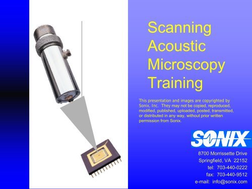
Scanning<br />
Acoustic<br />
Microscopy<br />
Training<br />
This presentation and images are copyrighted by<br />
Sonix, Inc. They may not be copied, reproduced,<br />
modified, published, uploaded, posted, transmitted,<br />
or distributed in any way, without prior written<br />
permission from Sonix.<br />
8700 Morrissette Drive<br />
Springfield, VA 22152<br />
tel: 703-440<br />
440-02220222<br />
fax: 703-440<br />
440-9512<br />
e-mail: info@sonix.com
This presentation serves as a brief<br />
introduction into the theory and<br />
operation <strong>of</strong> scanning acoustic<br />
microscopes.<br />
2<br />
Copyright Sonix, Inc
Ultrasound Inspection,<br />
Using an Acoustic Microscope…<br />
• Ultrasound<br />
What does this<br />
thing do<br />
•Non-Destructive Testing<br />
•Example Images<br />
3<br />
Copyright Sonix, Inc
Ultrasound<br />
MEDICAL<br />
SONAR<br />
University <strong>of</strong> California Medical Center<br />
San Francisco, California<br />
What are are Ultrasonic Waves<br />
Ultrasonic waves refer refer to to sound waves above 20 20 kHz kHz<br />
(not (not audible to to the the human ear) ear)<br />
4<br />
Copyright Sonix, Inc
Non-Destructive Testing<br />
NDT utilizes various non-invasive<br />
measurement techniques, such as<br />
ultrasonics and radiography to<br />
determine the integrity <strong>of</strong> a<br />
component, structure, or material<br />
without destroying the usefulness<br />
<strong>of</strong> the item.<br />
5<br />
Copyright Sonix, Inc
Where an Acoustic Microscope is utilized.<br />
•Failure Analysis<br />
•Reliability<br />
•Process Control<br />
•Vendor Qualification<br />
•Production<br />
•Quality Control<br />
•Research<br />
6<br />
Copyright Sonix, Inc
Common Applications<br />
•Plastic encapsulated IC IC packages<br />
•Flip Chips<br />
•Bonded Wafers<br />
•Printed Circuit Boards<br />
•Capacitors<br />
•Ceramics<br />
•Metallic<br />
•Power Devices/Hybrids<br />
•Medical Devices<br />
•Material Characterization<br />
7<br />
Copyright Sonix, Inc
Examples<br />
Lid seal voids<br />
Delamination<br />
BGA die attach<br />
Die Crack<br />
8<br />
Copyright Sonix, Inc
Examples<br />
Die Top<br />
Delamination<br />
Mold compound voids<br />
Flip Chip Underfill<br />
Voids<br />
9<br />
Die Tilt, B-Scan<br />
Die Pad delamination<br />
Copyright Sonix, Inc<br />
Die Attach Voids
Ultrasound Inspection<br />
•Theory<br />
•System Components<br />
•Transducers<br />
10<br />
Copyright Sonix, Inc
Ultrasonic Waves<br />
Characteristics <strong>of</strong> <strong>of</strong> Ultrasonic Waves<br />
•• Freely Freely propagate through liquids liquids and and solids solids<br />
•• Reflect Reflect at at boundaries <strong>of</strong> <strong>of</strong> internal internal flaws flaws and and<br />
change change <strong>of</strong> <strong>of</strong> material<br />
•• Capable <strong>of</strong> <strong>of</strong> being being focused, straight straight<br />
transmission<br />
University <strong>of</strong> California Medical Center<br />
San Francisco, California<br />
•• Suitable for for Real-Time processing<br />
•• Harmless to to the the human human body body<br />
•• Non-destructive to to material<br />
11<br />
Copyright Sonix, Inc
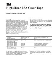
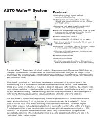
Ultrasonic Inspection<br />
Ultrasound<br />
•• A transducer transducer produces produces a high high<br />
frequency frequency sound sound wave wave which which<br />
interacts interacts with with the the sample. sample.<br />
•• High High frequency frequency sound sound waves waves<br />
can can not not propagate propagate through through air. air.<br />
•• Couplant- Couplant-A material material used used to to<br />
carry carry the the high high frequency frequency sound sound<br />
waves. waves.<br />
•Water •Water is is the the most most common common<br />
couplant couplant for for immersion immersion<br />
testing. testing.<br />
Inspection Modes<br />
•Pulse •Pulse Echo Echo<br />
•Through •Through Transmission<br />
Transmission<br />
Transducer<br />
H 2 O<br />
Coupling<br />
Receive<br />
12<br />
Copyright Sonix, Inc
Scanner<br />
The scanner consists <strong>of</strong> a three axis system, X, Y, and Z. The<br />
motor controller directs the movement <strong>of</strong> these axes.<br />
F<br />
o<br />
c<br />
u<br />
s<br />
Z<br />
A<br />
x<br />
i<br />
s<br />
X-Axis<br />
Y-Axis<br />
Step<br />
13<br />
ScanCopyright Sonix, Inc
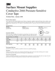
Transducers<br />
High Frequency<br />
Short Focus<br />
Low Frequency<br />
Long Focus<br />
1. 1. Higher Higher resolution resolution<br />
2. 2. Shorter Shorter focal focal lengths lengths<br />
3. 3. Less Less penetration penetration<br />
(Thinner (Thinner packages) packages)<br />
1. 1. Lower Lower resolution resolution<br />
2. 2. Longer Longer focal focal lengths lengths<br />
3. 3. Greater Greater penetration penetration<br />
(Thicker (Thicker packages) packages)<br />
General<br />
General<br />
rules:<br />
rules:<br />
•<br />
•<br />
Ultra<br />
Ultra<br />
High<br />
High<br />
Frequency<br />
Frequency<br />
(200+<br />
(200+<br />
MHz)<br />
MHz)<br />
for<br />
for<br />
flip<br />
flip<br />
chips<br />
chips<br />
and<br />
and<br />
wafers.<br />
wafers.<br />
•<br />
•<br />
High<br />
High<br />
Frequency<br />
Frequency<br />
(50-75<br />
(50-75<br />
MHz)<br />
MHz)<br />
for<br />
for<br />
thin<br />
thin<br />
plastic<br />
plastic<br />
packages.<br />
packages.<br />
(110MHz-UHF)<br />
(110MHz-UHF)<br />
for<br />
for<br />
flip<br />
flip<br />
chips.<br />
chips.<br />
•<br />
•<br />
Low<br />
Low<br />
Frequency<br />
Frequency<br />
(15<br />
(15<br />
MHz)<br />
MHz)<br />
for<br />
for<br />
thicker<br />
thicker<br />
plastic<br />
plastic<br />
packages.<br />
packages.<br />
Copyright Sonix, Inc<br />
14
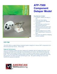
Transducer Beam Pr<strong>of</strong>ile<br />
Depth <strong>of</strong> Field<br />
The purple region<br />
is referred to as the<br />
focal area or depth<br />
<strong>of</strong> field <strong>of</strong> the<br />
transducer beam.<br />
15<br />
Copyright Sonix, Inc
Typical Transducer Selection<br />
Sample Application<br />
Transducer<br />
16<br />
T/X Receiver<br />
PLCC, QFP, PQFP<br />
Power Pak<br />
BGA Top<br />
Capacitors<br />
TSOP<br />
Flip Chip Underfill<br />
Flip Chip Interconnect<br />
Bonded Wafer<br />
Bonded Wafer<br />
10 MHz w/0.75” focus<br />
15 MHz w/0.5” focus<br />
15 MHz w/0.5” focus<br />
50-75 MHz w/12mm focus<br />
75 MHz w/12mm focus<br />
75 MHz w/12mm focus<br />
110 MHz w/8mm focus<br />
UHF w/ 5.9 mm focus<br />
110 MHz w/8mm focus<br />
UHF w/ 5.9 mm focus<br />
Copyright Sonix, Inc
ABC’s Of Acoustics<br />
•Acoustic Reflections<br />
•Acoustic Waveforms<br />
•Image Display<br />
17<br />
Copyright Sonix, Inc
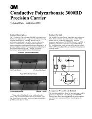
Acoustic Properties<br />
Material Density LongitudinalWave Acoustic Impedance<br />
(g/cm 3 ) Velocity (m/s) (kg/m 2 s) (x10 6 )<br />
Water (20 0 C) 1.00 1483 1.48<br />
Alcohol (20 0 C) 0.79 1168 0.92<br />
Air (20 0 C) 0.00 344 0.00<br />
Silicon 2.33 8600 20.04<br />
Gold 19.3 3240 62.53<br />
Copper 8.90 4700 41.83<br />
Aluminum 2.70 6260 16.90<br />
Epoxy Resin 1.20 2600 3.12<br />
Resin (for IC pkg) 1.72 3930 6.76<br />
Glass (Quartz) 2.70 5570 15.04<br />
Alumina (AL 2 O 3 ) 3.80 10410 39.56<br />
18<br />
Copyright Sonix, Inc
Sound Reflection<br />
•Acoustic Material Properties<br />
•density (r)<br />
•velocity <strong>of</strong> sound in material (c)<br />
•acoustic impedance (Z= rc)<br />
19<br />
Copyright Sonix, Inc
Sound Reflection<br />
Whenever a sudden change in<br />
acoustic impedance is encountered,<br />
like at a material boundary, a portion<br />
<strong>of</strong> sound is reflected and the<br />
remainder propagates through the<br />
boundary.<br />
20<br />
Copyright Sonix, Inc
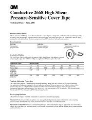
Reflection vs. Transmission<br />
Incident Energy<br />
Z= ρC<br />
Water Z 1<br />
Plastic Z 2<br />
Z 1<br />
= ρ C where:<br />
ρ=1.00 gram/cm 3<br />
C= 1.5 x 10 6<br />
Z 1<br />
= 1.5 x 10 6<br />
Reflected Energy<br />
Transmitted Energy<br />
Z 2<br />
= ρ C where:<br />
ρ =2.00 gram/cm 3<br />
C= 2.00 x 10 6<br />
Z 2<br />
= 4.00 x 10 6<br />
T<br />
T<br />
T<br />
=<br />
=<br />
=<br />
2 ( Z<br />
1<br />
)<br />
( Z + Z )<br />
2<br />
2 ( 1 . 5 )<br />
( 4 . 0 + 1 . 5 )<br />
( 3 . 0 )<br />
( 5 . 5 )<br />
1<br />
45% <strong>of</strong> the<br />
sound entering<br />
the boundary is<br />
reflected.<br />
R<br />
R<br />
R<br />
=<br />
=<br />
=<br />
( Z<br />
2<br />
− Z<br />
1<br />
)<br />
( Z + Z )<br />
( 4<br />
( 4<br />
( 2<br />
( 5<br />
2<br />
. 0<br />
. 0<br />
. 5<br />
. 5<br />
)<br />
)<br />
−<br />
+<br />
1<br />
1<br />
1<br />
. 5<br />
. 5<br />
)<br />
)<br />
21<br />
T<br />
=<br />
. 55<br />
Copyright Sonix, IncR<br />
=<br />
. 45
Reflected Sound Information<br />
Measuring the reflected<br />
ultrasound can provide:<br />
• Amplitude Information<br />
• Polarity Information<br />
• Time Information<br />
22<br />
Copyright Sonix, Inc
ABC’s <strong>of</strong> Acoustics<br />
A-Scan- The raw ultrasonic data. It is the received RF signal<br />
from a single point (x,y).<br />
B-Scan- A line <strong>of</strong> A-scans. (Vertical cross-section)<br />
23<br />
C-Scan-Data from a specified depth over the<br />
entire scan area. (Horizontal cross-section.<br />
Copyright Sonix, Inc
A-SCAN<br />
Initial Pulse<br />
Transducer<br />
Front surface<br />
Interface <strong>of</strong><br />
interest<br />
Sample<br />
Back surface<br />
24<br />
Copyright Sonix, Inc
Ultrasonic Waveforms<br />
The Black signal is commonly<br />
referred to as the initial pulse or the<br />
main bang. This signal occurs at<br />
Zero microseconds.<br />
The Red signal is commonly referred<br />
to as the front surface. This<br />
represents the first interface the sound<br />
encounters.<br />
1<br />
2<br />
The Green signal would be considered<br />
the area <strong>of</strong> interest. A data gate would<br />
be positioned over this signal or group<br />
<strong>of</strong> signals for evaluation.<br />
1 2<br />
The Blue signal is commonly referred to<br />
as a back wall echo or back surface.<br />
Just as the name implies it is the back<br />
or bottom <strong>of</strong> the sample.<br />
25<br />
Copyright Sonix, Inc
A-SCAN<br />
100%<br />
+ Phase<br />
Amplitude %FSH 0%<br />
-100%<br />
_<br />
Phase<br />
Time / Depth<br />
A-Scans provide the following information:<br />
1. Amplitude / % <strong>of</strong> full screen height (FSH)<br />
2. Phase / positive or negative peak<br />
3. Time / Depth<br />
26<br />
Copyright Sonix, Inc
C-SCAN<br />
IP<br />
Front surface<br />
Back surface<br />
Area <strong>of</strong> interest<br />
The red box (data gate) indicates<br />
the depth <strong>of</strong> information.<br />
27<br />
Copyright Sonix, Inc
B-Scan<br />
Front surface<br />
Signal from<br />
indication<br />
Back surface<br />
The blue line (B-scan gate) represents the depth<br />
<strong>of</strong> information recorded.<br />
Front surface<br />
28<br />
Signal from<br />
indication<br />
Back surface<br />
Copyright Sonix, Inc
Inspection Modes<br />
•Pulse Echo<br />
•Through Transmission<br />
29<br />
Copyright Sonix, Inc
Inspection Modes<br />
Pulse-Echo<br />
Through Transmission<br />
Transmit<br />
Transmit<br />
&<br />
Receive<br />
Receive<br />
30<br />
Pulse-Echo<br />
Pulse-Echo<br />
-<br />
-<br />
One<br />
One<br />
Transducer<br />
Transducer<br />
Through<br />
•<br />
•<br />
Ultrasound<br />
Ultrasound<br />
reflected<br />
reflected<br />
from<br />
from<br />
the<br />
the<br />
sample<br />
sample<br />
is<br />
is<br />
used. Through<br />
Transmission<br />
Transmission<br />
-<br />
-<br />
Two<br />
Two<br />
Transducers<br />
Transducers<br />
used. •<br />
•<br />
•<br />
Can<br />
Can<br />
determine<br />
determine<br />
which<br />
which<br />
interface<br />
interface<br />
is<br />
is<br />
delaminated. •<br />
Ultrasound<br />
Ultrasound<br />
transmitted<br />
transmitted<br />
through<br />
through<br />
the<br />
the<br />
delaminated. sample<br />
•<br />
•<br />
Requires<br />
Requires<br />
scanning<br />
scanning<br />
from<br />
from<br />
both<br />
both<br />
sides<br />
sides<br />
to<br />
to<br />
inspect sample<br />
is<br />
is<br />
used.<br />
used.<br />
inspect •<br />
all<br />
all<br />
interfaces.<br />
•<br />
One<br />
One<br />
Scan<br />
Scan<br />
reveals<br />
reveals<br />
delamination<br />
delamination<br />
at<br />
at<br />
all<br />
all<br />
interfaces.<br />
interfaces.<br />
•<br />
•<br />
Provides<br />
Provides<br />
images<br />
images<br />
with<br />
with<br />
high<br />
high<br />
degree<br />
degree<br />
<strong>of</strong><br />
<strong>of</strong><br />
spatial<br />
interfaces.<br />
spatial •<br />
detail.<br />
•<br />
No<br />
No<br />
way<br />
way<br />
to<br />
to<br />
determine<br />
determine<br />
which<br />
which<br />
interface<br />
interface<br />
is<br />
is<br />
detail.<br />
delaminated.<br />
•<br />
•<br />
Peak<br />
Peak<br />
Amplitude,<br />
Amplitude,<br />
Time<br />
Time<br />
<strong>of</strong><br />
<strong>of</strong><br />
Flight<br />
Flight<br />
(TOF)<br />
(TOF)<br />
and<br />
delaminated.<br />
and •<br />
Phase<br />
Phase<br />
Inversion<br />
Inversion<br />
measurement<br />
•<br />
Less<br />
Less<br />
spatial<br />
spatial<br />
resolution<br />
resolution<br />
than<br />
than<br />
pulse-echo.<br />
pulse-echo.<br />
measurement<br />
•<br />
Copyright •<br />
Commonly<br />
Sonix, Commonly<br />
used<br />
Inc used<br />
to<br />
to<br />
verify<br />
verify<br />
pulse-echo<br />
pulse-echo<br />
results.<br />
results.
Inspection Modes<br />
Pulse-Echo<br />
Front Surface<br />
Back surface<br />
1<br />
2<br />
Transmit<br />
&<br />
Receive<br />
1<br />
Front Surface<br />
Air Gap<br />
Air Gap<br />
2<br />
31<br />
Copyright Sonix, Inc
Inspection Modes<br />
Through Transmission<br />
1<br />
1<br />
2<br />
3<br />
Transmit<br />
2<br />
Receive<br />
3<br />
32<br />
Copyright Sonix, Inc
Focusing Sound<br />
33<br />
Copyright Sonix, Inc
Too Close<br />
1<br />
Focusing the Transducer<br />
Too Far<br />
Focused<br />
Too Close<br />
Focused<br />
2<br />
3<br />
2<br />
1<br />
Too Far<br />
3<br />
34<br />
Focusing an ultrasonic transducer is similar to focusing an<br />
optical microscope.<br />
When optimum focus is reached the signal will reach a<br />
maximum peak. (See the A-scans images to the left)<br />
Copyright Sonix, Inc
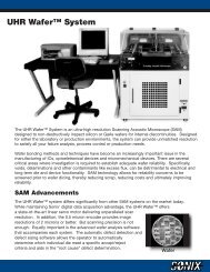
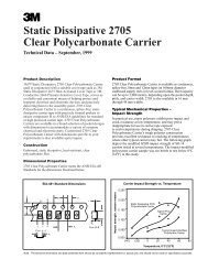
De-focused-- too close<br />
Water path<br />
Correct focus<br />
28%<br />
1. Note the<br />
time in<br />
microseconds<br />
<strong>of</strong> the signal<br />
at the different<br />
focus<br />
locations.<br />
(Red arrow)<br />
De-focused-- too far<br />
85%<br />
33%<br />
2. Also note<br />
the amplitude<br />
<strong>of</strong> the signal.<br />
(white box)<br />
When the<br />
signal is not<br />
in focus the<br />
amplitude is<br />
lower<br />
compared to<br />
that <strong>of</strong> correct<br />
focus.<br />
35<br />
Copyright Sonix, Inc<br />
*The ultrasound is focused on the surface <strong>of</strong> the penny.
Focusing Sound<br />
De-Focused - Too Close<br />
Focused on Die<br />
De-Focused - Too Far Away<br />
Amplitude = 42% Time =10.5 us Amplitude = 82% Time = 14.5 us Amplitude = 55% Time = 18.5 us<br />
36<br />
Copyright Sonix, Inc
Practical Application<br />
•Digital Oscilloscope<br />
•Front Surface Follower<br />
•Data Gates<br />
37<br />
Copyright Sonix, Inc
Digital Oscilloscope<br />
Initial pulse<br />
1st Echo<br />
2nd Echo<br />
3rd Echo<br />
38<br />
The 1st set <strong>of</strong> echoes is the<br />
area <strong>of</strong> interest, gate placement<br />
will be on this group.<br />
Copyright Sonix, Inc<br />
Multiple Echoes
Gates<br />
Gates Gates are are used used to to collect collect information information at at<br />
desired desired interfaces interfaces within within the the sample. sample.<br />
•The •The gate gate is is placed placed over over the the signal signal or or<br />
signals signals <strong>of</strong> <strong>of</strong> interest. interest.<br />
•The •The absolute absolute value value <strong>of</strong> <strong>of</strong> the the highest highest<br />
amplitude amplitude signal signal which which breaks breaks the the gate gate<br />
threshold threshold within within the the gated gated region region is is<br />
recorded. recorded. (Figure (Figure 1) 1)<br />
•If •If no no signal signal breaks breaks the the gate gate threshold threshold<br />
no no data data is is recorded. recorded. (Figure (Figure 2) 2)<br />
•Signal •Signal amplitude amplitude can can be be increased increased or or<br />
decreased decreased by by adjusting adjusting gain. gain.<br />
1<br />
2<br />
Gate Threshold<br />
Highest Amplitude signal<br />
No data recorded<br />
39<br />
Copyright Sonix, Inc
Practical Application<br />
•Image Data<br />
•Peak Amplitude<br />
•Time <strong>of</strong> Flight (TOF)<br />
•Phase Inversion<br />
40<br />
Copyright Sonix, Inc
Peak Amplitude<br />
Peak amplitude imaging is used<br />
when defects result in changes in<br />
the amount or strength <strong>of</strong><br />
ultrasound reflected. It is the most<br />
common type <strong>of</strong> imaging<br />
technique.<br />
41<br />
Copyright Sonix, Inc
Peak Amplitude<br />
Peak Amplitude<br />
100<br />
78<br />
75<br />
50<br />
X1<br />
25<br />
0<br />
Signal height is measured in absolute<br />
value for Peak Amplitude images.<br />
42<br />
Amplitude<br />
Copyright<br />
78%<br />
Sonix, Inc
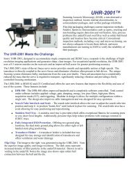
Time Of Flight<br />
Time <strong>of</strong> Flight (TOF) imaging<br />
works by measuring changes in<br />
the time it take sound to reflect <strong>of</strong>f<br />
a particular interface. Most<br />
commonly used to measure die<br />
tilting.<br />
43<br />
Copyright Sonix, Inc
Time Of Flight<br />
1<br />
X2<br />
X1<br />
2<br />
Time <strong>of</strong> Flight images provide a<br />
relative depth within a sample.<br />
Structures which appear white or<br />
light gray are closer to the surface<br />
<strong>of</strong> the sample.<br />
Structures which appear darker<br />
shades <strong>of</strong> gray or black are deeper<br />
within sample.<br />
44<br />
The peak signal for location 1 occurs at<br />
14.2 microseconds (light gray) while the<br />
peak signal for location 2 occurs at 14.6<br />
microseconds (dark gray).<br />
Copyright Sonix, Inc
Peak Amplitude vs. TOF<br />
Peak Amplitude<br />
Time <strong>of</strong> Flight<br />
X2<br />
X2<br />
X1<br />
X1<br />
Amplitude =73% Time =14.2 microseconds Amplitude =67% Time =14.6 microseconds<br />
Copyright Sonix, Inc<br />
45
Phase Inversion<br />
Phase Inversion imaging is used when<br />
defects cause changes in polarity (phase)<br />
<strong>of</strong> the signal. Most commonly used for top<br />
and back side imaging <strong>of</strong> plastic<br />
encapsulated devices.<br />
Do not use phase inversion imaging for flip<br />
chip, bonded wafer or die attach imaging.<br />
46<br />
Copyright Sonix, Inc
Phase Inversion<br />
Normal<br />
Phase Inverted<br />
47<br />
Copyright Sonix, Inc
X<br />
Phase Gate<br />
X<br />
RED<br />
Yellow<br />
Sonix Sonix uses uses a<br />
proprietary proprietary algorithm algorithm<br />
to to detect detect phase phase<br />
inversion. inversion. This This<br />
method method is is<br />
independent independent <strong>of</strong> <strong>of</strong> signal signal<br />
amplitude amplitude as as long long as as<br />
the the signal signal is is not not<br />
saturated saturated (100% (100%<br />
screen screen height). height).<br />
X<br />
48<br />
Copyright Sonix, Inc
Image Comparison & Correlation<br />
Through Transmission<br />
Peak Amplitude Image<br />
<strong>of</strong> Die Top<br />
Phase Inversion Image<br />
<strong>of</strong> Die Top<br />
Peak Amplitude Image<br />
<strong>of</strong> Die Attach<br />
49<br />
Copyright Sonix, Inc