
Create successful ePaper yourself
Turn your PDF publications into a flip-book with our unique Google optimized e-Paper software.
ABOUT OUR PRODUCTS<br />
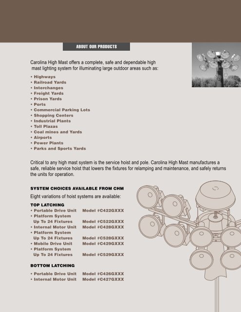
Carolina High Mast offers a complete, safe and dependable high<br />
mast lighting system for illuminating large outdoor areas such as:<br />
• Highways<br />
• Railroad Yards<br />
• Interchanges<br />
• Freight Yards<br />
• Prison Yards<br />
• Ports<br />
• Commercial Parking Lots<br />
• Shopping Centers<br />
• Industrial Plants<br />
• Toll Plazas<br />
• Coal mines and Yards<br />
• Airports<br />
• Power Plants<br />
• Parks and Sports Yards<br />
Critical to any high mast system is the service hoist and pole. Carolina High Mast manufactures a<br />
safe, reliable service hoist that lowers the fixtures for relamping and maintenance, and safely returns<br />
the units for operation.<br />
SYSTEM CHOICES AVAILABLE FROM <strong>CHM</strong><br />
Eight variations of hoist systems are available:<br />
TOP LATCHING<br />
• Portable Drive Unit<br />
• Platform System<br />
Up To 24 Fixtures<br />
• Internal Motor Unit<br />
• Platform System<br />
Up To 24 Fixtures<br />
• Mobile Drive Unit<br />
• Platform System<br />
Up To 24 Fixtures<br />
Model #C422GXXX<br />
Model #C522GXXX<br />
Model #C428GXXX<br />
Model #C528GXXX<br />
Model #C429GXXX<br />
Model #C529GXXX<br />
BOTTOM LATCHING<br />
• Portable Drive Unit<br />
• Internal Motor Unit<br />
Model #C426GXXX<br />
Model #C427GXXX
CAROLINA HIGH MAST<br />
TOP LATCH<br />
TOP LATCH<br />
The Standard Top Latch<br />
Lowering Device Includes:<br />
• Three-position stainless steel<br />
type 316 latching cams.<br />
• Three spring-loaded stainless<br />
steel centering arms.<br />
• Stainless steel hoist cables.<br />
• Stainless steel hardware.<br />
• Pre-wired aluminum distribution box.<br />
• Copper-free aluminum cover secured<br />
with stainless steel hardware.<br />
• Hot-dipped galvanized headframe,<br />
luminaire ring and fixture mounting<br />
tenons per ASTM -123.<br />
• Square D circuit breaker mounted<br />
in an aluminum enclosure.<br />
• Twist-lock weather-tight power<br />
connector set.<br />
• Internal winch system for use with<br />
portable power unit assembly<br />
(internal motorized winch and<br />
mobile drive system optional.)<br />
• Luminaire ring lowers to within<br />
four feet of pole base for servicing<br />
luminaires and other<br />
electrical equipment.<br />
• Luminaire ring accommodates<br />
up to 12 high mast fixtures,<br />
up to 16 floodlight fixtures, mounted<br />
symmetrically around the ring.<br />
Data in this publication subject to change without notice.<br />
2
Carolina High Mast<br />
TOP LATCH (Suggested Specifications)<br />
HEADFRAME ASSEMBLY<br />
The headframe assembly shall consist<br />
of a 1/4" thick minimum top plate, with<br />
sheave support plates fabricated from a<br />
minimum 11 gauge steel sheet. The<br />
sheave support plates shall be welded to<br />
the headframe base plate. All steel plates<br />
shall be laser cut for accuracy. The<br />
complete headframe assembly shall be<br />
hot-dipped galvanized per ASTM A-123<br />
after fabrication.<br />
Hoist cables shall operate over corrosion-resistant<br />
5-inch diameter aluminum<br />
steel sheaves. The entire cable groove<br />
surface shall be machined to eliminate<br />
any rough surface on which the cable<br />
shall ride.<br />
The main power cord shall be supported<br />
by a minimum of two 6-inch<br />
nonconductive thermoplastic polymer<br />
power cord sheaves grooved to provide<br />
for a nonabrasive smooth operation.<br />
A two-piece threaded male and female<br />
thermoplastic polymer insulating bushing<br />
assembly shall be installed on the<br />
headframe opening to prevent wear on<br />
the power cord as it travels up and down<br />
the pole.<br />
All sheaves shall have sintered bronze<br />
oilite bearings and run on a stainless steel<br />
axle secured with self-locking stainless steel<br />
hardware. Keeper bars shall be positioned<br />
at both ends of the sheave assemblies to<br />
keep the cord in its track during pole<br />
erection and during normal operation.<br />
The top latching assembly shall contain<br />
three (3) symmetrically located, extremely<br />
stout, precision-cast matching stainless steel<br />
latch pins and enclosed cam mechanisms<br />
to assure corrosion-resistant, trouble-free<br />
operation for years to come. All moving<br />
latch parts are bolted to the ring for<br />
servicing from the ground. The complete<br />
two-part latch pin and cam assembly shall<br />
be made of stainless steel (type 316)<br />
material. There shall be no moving latch<br />
parts or springs attached to the headframe<br />
assembly. All motion required to achieve<br />
latching or unlatching shall be internal<br />
to the latch cam. This will help prevent<br />
shock and vibration damage to the lamps<br />
and luminaires, as well as prevent the<br />
formation of ice buildup on the<br />
latching mechanism.<br />
Latching occurs by the alternate raising<br />
and lowering of the luminaire ring. When<br />
latching of the ring occurs, no horizontal<br />
movement of the fixtures (which can cause<br />
fixture damage) is permitted.<br />
When in the latch position the space<br />
between the headframe and the luminaire<br />
ring shall be no more than six inches.<br />
The use of “Z” type top latching system<br />
is not an acceptable alternate to the stainless<br />
steel latch cam.<br />
All hardware is corrosion-resistant<br />
stainless steel.<br />
The headframe assembly shall have<br />
a copper-free, spun aluminum cover,<br />
retained on its 360-degree perimeter<br />
by stainless steel hardware. The dome<br />
assembly shall provide a weather-tight<br />
seal against the elements for the<br />
headframe roller assemblies.<br />
The headframe shall bolt directly to<br />
the high mast pole. The headframe base<br />
plate and pole top plate shall have four<br />
9/16" x 3" slotted holes to accommodate<br />
1/2" type 18-8 stainless steel hardware.<br />
LUMINAIRE RING ASSEMBLY<br />
The luminaire ring shall be fabricated<br />
to 6" x 2" x #7 gauge spun steel per ASTM<br />
A-569, with the appropriate number of<br />
luminaire mounting tenons, hot-dipped<br />
galvanized per ASTM A-123 after fabrication.<br />
The luminaire ring shall have a prewired,<br />
weather-tight, corrosion-resistant<br />
aluminum enclosure with 3 conductor,<br />
16 AWG., type SEO 105-degree cable. The<br />
pre-wired distribution box shall be capable<br />
of accepting up to 16 fixtures, with 600-volt<br />
terminal blocks for each individual fixture<br />
wire. A weather-tight twist-lock test inlet<br />
shall be mounted to the terminal box to<br />
permit testing of the luminaires while the<br />
ring is in the lowered position.<br />
The luminaire ring shall contain three<br />
roller-contact, spring-loaded stainless steel<br />
centering arms with polymer rollers to<br />
center the ring and prevent shock to the<br />
lamps from impact of the ring with the pole.<br />
Highly visible 6" minimum retroreflective<br />
position indicator flags make for easy<br />
day or night operation.<br />
The three hoist cables shall be stainless<br />
steel wound anti-rotational aircraft<br />
cord, 3/16" diameter manufactured to<br />
meet MIL-W83420C. Winch cable shall<br />
be stainless steel 1/4" diameter antirotational<br />
cable, manufactured to meet<br />
MIL-W83420C. These special cables are<br />
specifically designed for lowering device<br />
applications and virtually make “twistings”<br />
a thing of the past. Swivel bearings may be<br />
used in the transition assembly but they<br />
shall not take the place of the antirotational<br />
cable.<br />
A transition assembly shall be supplied<br />
to attach the winch cable to the three hoist<br />
cables and the main power cord.<br />
The three hoist cables shall pass up<br />
through the pole shaft, over the headframe<br />
hoist cable sheaves, to the luminaire ring,<br />
where they travel through the stainless<br />
steel latch pin, stainless steel guides and<br />
compression spring assembly and terminate<br />
with a collet-type strand-vise device.<br />
WINCH PLATE ASSEMBLY<br />
A square “D” circuit breaker shall be<br />
mounted in an aluminum enclosure on the<br />
winch sub-plate to act as the disconnecting<br />
means for the lowering device. Pre-wired<br />
to the breaker shall be a twist-lock,<br />
weather-tight connector matching those<br />
used in the system, mounted to an 8' tail<br />
of power cord of the same type, gauge and<br />
number of conductors as the power cord.<br />
This cord and connector shall be used to<br />
alternately supply power to the lowering<br />
device system, the test inlet and the<br />
portable power unit assembly.<br />
The winch shall be an enclosed oil-bath<br />
worm gear winch, set with a reduction<br />
ratio of 30 to 1. The self-locking precision<br />
winch guards against ring runaway in the<br />
event of power failure.<br />
PORTABLE POWER UNIT ASSEMBLY<br />
(MODEL #C408GXXX)<br />
The portable power unit shall<br />
incorporate the heavy-duty, reversing<br />
type drive motor, torque limiter, drive<br />
shaft and electrical controls. The torque<br />
limiter is factory set to provide safe<br />
reliable operation. A twenty-five-foot-long<br />
cord on the remote electrical control box<br />
provides for remote operation of the<br />
portable power unit. The drive motor is<br />
a heavy duty 120-volt reversing electric<br />
drill. The portable power unit shall be<br />
provided with a weatherproof, portable,<br />
enclosed stepdown transformer to operate<br />
the 120-volt power unit.<br />
3<br />
Data in this publication subject to change without notice.
CAROLINA HIGH MAST<br />
BOTTOM LATCH<br />
BOTTOM LATCH<br />
The Standard Bottom Latch<br />
Lowering Device Includes:<br />
• Three-position aluminum<br />
guide blocks.<br />
• 14 fixed-caster rollers<br />
(three spring-loaded stainless<br />
steel centering arms or PVC<br />
scrub rings optional.)<br />
• Stainless steel hoist cables.<br />
• Stainless steel hardware.<br />
• Pre-wired aluminum<br />
distribution box.<br />
• Copper-free aluminum<br />
cover secured with stainless steel.<br />
• Hot-dipped galvanized headframe,<br />
luminaire ring and fixture mounting<br />
tenons per ASTM A-123.<br />
• Square D circuit breaker mounted<br />
in an aluminum enclosure.<br />
• Twist-lock weather-tight power<br />
connector set.<br />
• Internal winch system for use<br />
with a portable power unit<br />
assembly (internal motorized<br />
winch and mobile drive<br />
system optional.)<br />
• Luminaire ring lowers to within<br />
four feet of the pole base for<br />
servicing luminaires and other<br />
electrical equipment.<br />
• Luminaire ring accommodates<br />
up to 12 high mast fixtures,<br />
up to 16 floodlight fixtures.<br />
Data in this publication subject to change without notice.<br />
4
Carolina High Mast<br />
BOTTOM LATCH (Suggested Specifications)<br />
HEADFRAME ASSEMBLY<br />
The headframe assembly shall consist<br />
of a 1/4" thick minimum top plate, with<br />
sheave support plates fabricated from a<br />
minimum 11-gauge steel sheet. The<br />
sheave support plates shall be welded to<br />
the headframe base plate. All steel plates<br />
shall be laser-cut for accuracy. The<br />
complete headframe assembly shall be<br />
hot-dipped galvanized per ASTM A-123<br />
after fabrication.<br />
Hoist cables shall operate over corrosion-resistant<br />
5-inch diameter aluminum<br />
steel sheaves. The entire cable groove<br />
surface shall be machined to eliminate<br />
any rough surface on which the cable<br />
shall ride.<br />
The main power cord shall be supported<br />
by a minimum of two 6-inch<br />
non-conductive thermoplastic polymer<br />
power cord sheaves grooved to provide<br />
for a nonabrasive smooth operation. A<br />
two-piece threaded male and female<br />
thermoplastic polymer insulated bushing<br />
assembly shall be installed on the<br />
headframe opening to prevent wear on<br />
the power cord as it travels up and down<br />
the pole.<br />
All sheaves shall have sintered bronze<br />
oilite bearings and run on a stainless steel<br />
axle secured with self-locking stainless<br />
steel hardware. Keeper bars shall be<br />
positioned at both ends of the sheave<br />
assemblies to keep the cord in its track<br />
during pole erection and during<br />
normal operation.<br />
On the underside of the headframe<br />
shall mount three cast aluminum guide<br />
sockets. The socket opening shall be<br />
tapered cone-shaped for locking and<br />
aligning the stainless steel locking pin<br />
mounted on the luminaire ring up against<br />
the headframe. The stainless steel locking<br />
pin shall insert a minimum of 4-1/2" into<br />
the cast aluminum guide socket. When<br />
in the latch position, the space between<br />
the headframe and the luminaire ring<br />
shall be no more than four inches when<br />
in the latched position.<br />
All hardware is corrosion-resistant<br />
stainless steel.<br />
The headframe assembly shall have<br />
a copper-free, spun aluminum cover,<br />
retained on its 360-degree perimeter<br />
by a stainless steel hardware. The dome<br />
assembly shall provide an airtight seal<br />
against the elements for the headframes<br />
roller assemblies.<br />
The headframe shall bolt directly to<br />
the high mast pole. The headframe base<br />
plate and pole top plate shall have four<br />
9/16" x 3" slotted holes on a 10 3/4" arc<br />
to accommodate 1/2" type 18-8 stainless<br />
steel hardware.<br />
LUMINAIRE RING<br />
ASSEMBLY<br />
The luminaire ring shall be fabricated<br />
to 6" x 2" x #7-gauge spun steel per<br />
ASTM A-569, with the appropriate<br />
number of luminaire mounting tenons,<br />
hot-dipped galvanized per ASTM A-123<br />
after fabrication. The luminaire ring shall<br />
have a pre-wired weather-tight corrosionresistant<br />
aluminum enclosure with 3<br />
conductor, 16 AWG., type SEO 105-degree<br />
cable. The pre-wired distribution box<br />
shall be capable of accepting up to 16<br />
fixtures, with 600-volt terminal blocks for<br />
each individual fixture wire. A weathertight<br />
twist-lock test inlet shall be mounted<br />
to the terminal box to permit testing of<br />
the luminaires while the ring is in the<br />
lowered position.<br />
The luminaire ring shall contain at least<br />
14 fixed rollers mounted on the inside of<br />
the ring to protect the ring from impacting<br />
with the pole. Rollers shall be fabricated<br />
from impact-resistant non-marking PVC,<br />
rolling on stainless steel shafts.<br />
Highly visible 6" minimum retroreflective<br />
indicator flags shall be mounted on the<br />
ring which will provide positive indication<br />
at the handhole that the required 300<br />
pounds of total seating force has been<br />
applied, visible from an extended operating<br />
position 20' from the base of the pole.<br />
The three hoist cables shall be<br />
stainless steel wound anti-rotational<br />
aircraft cord, 3/16" diameter manufactured<br />
to meet MIL-W83420C. Winch cable<br />
shall be stainless steel 1/4" diameter antirotational<br />
cable, manufactured to meet<br />
MIL-W83420C. These special cables are<br />
specifically designed for lowering device<br />
applications and virtually make “twistings”<br />
a thing of the past. Swivel bearings may<br />
be used in the transition assembly but<br />
they shall not take the place of the<br />
anti-rotational cable.<br />
The three hoist cables shall pass up<br />
through the pole shaft, over the headframe<br />
sheaves, to the luminaire ring, where<br />
they travel through guides and a<br />
compression spring and terminate<br />
with a collet-type device.<br />
A safety mechanism shall be located<br />
in the base of the pole and consist of a<br />
stainless steel safety cable and hook to act<br />
as a backup to the winch cable assembly<br />
in maintaining the tension on the transition<br />
assembly. The safety cable shall be secured<br />
to the foundation or anchor bolts and not<br />
attached to the pole structure.<br />
WINCH PLATE ASSEMBLY<br />
A square D circuit breaker shall be<br />
mounted in an aluminum enclosure on the<br />
winch sub-plate to act as the disconnecting<br />
means for the lowering device. Pre-wired<br />
to the breaker shall be a twist-lock,<br />
weather-tight connector matching those<br />
used in the system, mounted to an 8' tail<br />
of power cord of the same type, gauge<br />
and number of conductors as the power<br />
cord. This cord and connector shall be<br />
used to alternately supply power to the<br />
lowering device system, the test inlet and<br />
the portable power unit assembly.<br />
The winch shall be an enclosed oil-bath<br />
worm gear winch, set with a reduction<br />
ratio of 30 to 1. The self-locking precision<br />
winch guards against ring runaway in the<br />
event of power failure.<br />
PORTABLE POWER<br />
UNIT ASSEMBLY<br />
(MODEL #C408GXXX)<br />
The portable power unit shall incorporate<br />
the drive motor, torque limiter, drive<br />
shaft and electrical controls. The torque<br />
limiter is factory set to provide safe,<br />
reliable operation. A twenty-five-foot-long<br />
cord on the remote electrical control box<br />
provides for remote operation of the<br />
portable power unit. The drive motor is<br />
a heavy-duty 120-volt reversing electric<br />
drill. The portable power unit shall be<br />
provided with a weatherproof, portable,<br />
enclosed stepdown transformer to operate<br />
the 120-volt power unit.<br />
5<br />
Data in this publication subject to change without notice.
CAROLINA HIGH MAST<br />
PORTABLE POWER UNIT<br />
INSTALLED IN POLE<br />
PORTABLE POWER UNIT ASSEMBLY (MODEL #C408GXXX)<br />
MOBILE PLATFORM SYSTEM (MODEL #C508GXXX)<br />
The portable power unit shall incorporate the drive motor, torque<br />
limiter, drive shaft and electrical controls. The torque limiter is<br />
factory set to provide safe reliable operation. A twenty-five-footlong<br />
cord on the remote electrical control box provides for remote<br />
operation of the portable power unit. The drive motor is a heavy<br />
duty 120-volt reversing electric drill. The portable power unit shall<br />
be provided with a weatherproof, portable, enclosed stepdown<br />
transformer to operate the 120-volt power unit.<br />
Data in this publication subject to change without notice.<br />
6
Carolina High Mast<br />
MOBILE DRIVE UNIT<br />
NOTES:<br />
1. Unit is trailerable, eliminating<br />
loading and unloading hassles.<br />
2. Fully adjustable arm allows<br />
operation of lowering device<br />
from uneven ground.<br />
3. For retrofit situations, unit can<br />
operate lowering device<br />
through a single 5’ x 8’ hand hole.<br />
4. Above 120 volts the voltage<br />
transformer is integral.<br />
5. Tongue may be tilted<br />
for storage.<br />
6. All adjustment pins are<br />
safety clipped.<br />
7. 25-foot cord makes remote<br />
operation easy.<br />
8. All winches wound with<br />
1/4-inch diameter stainless<br />
steel anti-rotational cable.<br />
This cable is specifically<br />
manufactured for lowering<br />
device applications.<br />
ORDERING INFORMATION<br />
POLE BASE POWER MOBILE DRIVE CAT. NO.<br />
480 volts C429G001<br />
277 volts C429G002<br />
240 volts C429G002<br />
208 volts C429G002<br />
347 volts C429G002<br />
Mobile Platform System<br />
C529G001<br />
The mobile cart drive allows one maintenance<br />
person to operate the service platform, lowering<br />
the fixtures to ground level for service.<br />
ATTACH SAFETY<br />
CABLE WHEN<br />
NOT IN USE. ALSO<br />
USE TO SECURE<br />
CABLE ASM,<br />
WHEN SAFETY<br />
CABLE IS NOT<br />
REQUIRED.<br />
SAFETY CABLE<br />
INSTALLATION<br />
1,000 in. TYPICAL<br />
(25.4 MM TYPICAL)<br />
72,000 in.<br />
(1829 mm)<br />
REMOTE SWITCH<br />
and 25 FT (7.6M cord<br />
STEPDOWN<br />
TRANSFORMER<br />
STORAGE BOX for<br />
REMOTE SWITCH<br />
and CORD<br />
DRIVE MOTOR<br />
TORQUE<br />
LIMITER<br />
TRACKING<br />
PULLEY<br />
CIRCUIT<br />
BREAKER BOX<br />
14,000 in.<br />
(368mm)<br />
SAFETY CABLE<br />
ADJUSTABLE<br />
HITCH<br />
FOR 2,000 in.<br />
(51mm) BALL<br />
TONGUE TILTS UP<br />
FOR STORAGE<br />
13,000 in. (330MM) WHEELS<br />
FOR EASY TRANSPORT<br />
WINCH<br />
ADJUSTABLE<br />
HEAD<br />
attached to<br />
handhole by<br />
two j-bolts<br />
105,000 IN.<br />
(2,667MM)<br />
BOTH DRIVE AND WINCH ARE EXTERNAL TO THE POLE, MOUNTED TO A MOBILE CART.<br />
7<br />
Data in this publication subject to change without notice.
CAROLINA HIGH MAST<br />
INTERNAL MOTOR & TRANSITION ASSEMBLY<br />
NOTE:<br />
This is for 347 and 480 volt system only. For 208, 240 and<br />
277 volt systems, see Internal Motor as shown on page 9.<br />
Internal Motorized Winch<br />
Model #C428GXXX When used with Top Latch<br />
Model #C427GXXX When used with Bottom Latch<br />
Model #C528GXXX When used with Top Latch<br />
Mobile Platform System<br />
Data in this publication subject to change without notice.<br />
8
Carolina High Mast<br />
INTERNAL MOTOR<br />
THE WINCH PLATE ASSEMBLY<br />
A square D circuit breaker shall be mounted in an aluminum enclosure on the winch<br />
sub-plate to act as the disconnecting means for the lowering device. Pre-wired to the<br />
breaker shall be a twist-lock, weather-tight connector matching those used in the system,<br />
mounted to an 8’ tail of power cord of the same type, gauge and number of conductors as<br />
the power cord. This cord and connector shall be used to alternately supply power to<br />
the lowering device system, the test inlet and the portable power unit assembly.<br />
The winch shall be an enclosed oil-bath worm gear winch, set with a reduction ratio<br />
of 30 to 1. The self-locking precision winch guards against ring runaway in the event<br />
of power failure.<br />
THE INTERNAL MOTOR ASSEMBLY<br />
The internal motor assembly shall incorporate a heavy-duty, reversing type drive motor,<br />
torque limiter, drive shaft and electrical controls. The torque limiter is factory set to<br />
provide safe reliable operation. A twenty-five-foot-long cord on the remote electrical<br />
control box provides for remote operation of the portable power unit.<br />
When necessary, a step down transformer shall be provided to operate the internal motor.<br />
For 208, 240, 277 Volt Systems<br />
For 347 and 480 Volt Systems Only<br />
9<br />
Data in this publication subject to change without notice.
CAROLINA HIGH MAST<br />
HIGH MAST LUMINAIRE MOUNTING ARM ARRANGEMENT<br />
MOUNTING ARM ARRANGEMENT<br />
OPTIONS<br />
NOTE:<br />
*Maximum number of<br />
luminaires is 12 regardless<br />
of arm arrangement<br />
ARM<br />
ORIENTATION<br />
ARM<br />
DEGREES<br />
NUMBER ARMS<br />
PER POLE<br />
NUMBER LUMINAIRES<br />
PER POLE<br />
(A) Ring-with-fixture<br />
dimension (for<br />
clearance planning)<br />
120<br />
3<br />
3<br />
Six-fixture orientation:<br />
Arm+21 inches (533mm);<br />
Diameter=99 inches<br />
(2,515mm)<br />
90<br />
4<br />
4<br />
Twelve-fixture orientation:<br />
Tee Arm=32 inches (762mm);<br />
Diameter=119 inches<br />
(2,972mm)<br />
72<br />
60<br />
5<br />
6<br />
5<br />
6<br />
FEATURES<br />
• Arms are constructed of two-inch (51mm) round steel pipe (2 3/8-inch/60mm OD)<br />
• Hot-dipped galvanized after fabrication<br />
• Arms will be equally spaced around ring<br />
• Counterweight is used to balance loaded arms<br />
HOW TO ORDER<br />
When ordering service hoist, specify quantity<br />
of luminaires per ring. (Appropriate number<br />
of arms shall be bolted to the ring.)<br />
Data in this publication subject to change without notice.<br />
10
Carolina High Mast<br />
FLOODLIGHT MOUNTING AND AIMING 3-ARM, 3-12 FLOODLIGHTS ARM ARRANGEMENT<br />
3-ARM, 3-12 ARM ARRANGEMENT<br />
OPTIONS<br />
ARM<br />
ORIENTATION<br />
ARM<br />
DEGREES<br />
NUMBER ARMS<br />
PER POLE<br />
NUMBER FLOODLIGHTS<br />
PER POLE<br />
NOTE:<br />
*Maximum number of<br />
floodlights is 12 regardless<br />
of arm arrangement<br />
120<br />
3<br />
3–12<br />
(A) Ring-with-fixture<br />
dimension (for<br />
clearance planning)<br />
90<br />
4<br />
4–16*<br />
Sixteen-fixture orientation:<br />
Arm=54 inches (1,372mm);<br />
Diameter=142 inches<br />
(3,607mm)<br />
72<br />
5<br />
5–10<br />
60<br />
6<br />
6–12<br />
FEATURES<br />
• Arms are constructed of two-inch (51mm) square steel pipe (2 3/8 inch/60mm OD),<br />
27 or 54 inches (686 or 1,372mm) long<br />
• Hot-dipped galvanized after fabrication<br />
• Arms will be equally spaced around ring<br />
• Counterweight is used to balance loaded arms when necessary.<br />
HOW TO ORDER<br />
When ordering service hoist, specify quantity<br />
of floodlights per ring. (Appropriate number<br />
of arms shall be bolted to the ring.)<br />
11<br />
Data in this publication subject to change without notice.
C A R O L I N A H
I G H M A S T<br />
Carolina High Mast offers a<br />
complete, safe and dependable high<br />
mast lighting system for illuminating<br />
large outdoor areas such as:<br />
• Highways<br />
• Railroad Yards<br />
• Interchanges<br />
• Freight Yards<br />
• Prison Yards<br />
• Ports<br />
• Commercial Parking Lots<br />
• Shopping Centers<br />
• Industrial Plants<br />
• Toll Plazas<br />
• Coal mines and Yards<br />
• Airports<br />
• Power Plants<br />
• Parks and Sports Yards
CAROLINA HIGH MAST<br />
TOP LATCH MOBILE SPORTRACK SYSTEM SPECIFICATIONS<br />
THE STANDARD TOP-LATCH SYSTEM FOR IN<br />
EXCESS OF 12 FIXTURES INCLUDES:<br />
Mobile Platform System with Top-Latching<br />
Crossarm Service Platform for 13 to 21 fixtures<br />
(shown with Mobile Cart Drive Assembly)<br />
• Three (3) symmetrically<br />
located stainless steel<br />
type 316 latching cams.<br />
• Two (2) galvanized steel<br />
stabilizing pins.<br />
• Three (3) spring-loaded<br />
stainless steel centering<br />
arms for stabilized raising<br />
and lowering.<br />
• 1/4 " galvanized steel hoist<br />
cables. Stainless steel<br />
is optional.<br />
• Stainless steel hardware.<br />
• Copper-free aluminum<br />
cover secured with stainless<br />
steel hardware.<br />
• Hot dipped galvanized<br />
headframe assembly per<br />
ASTM A-123.<br />
• Circuit breakers mounted<br />
in an aluminum enclosure.<br />
• Twist-lock weather-tight<br />
power connector set.<br />
• Mobile cart drive system.<br />
(Portable power units and<br />
internal motorized systems<br />
are available. Contact the<br />
factory for more information<br />
on these drive systems.)<br />
• Mobile crossarm platform<br />
which lowers to within<br />
five (5) feet of pole base<br />
for servicing fixtures and<br />
other electrical equipment.<br />
• Hot-dipped galvanized<br />
steel pole, per ASTM A-123.<br />
TOP PLATE ASSEMBLY<br />
The headframe assembly shall consist of<br />
1/4" thick minimum top plate, with sheave<br />
support plates fabricated from a minimum<br />
11-gauge steel sheet. The sheave support plates<br />
shall be wedged to the headframe base plate.<br />
All steel plates shall be laser cut for accuracy.<br />
The complete headframe assembly shall be<br />
hot dipped galvanized per ASTM A-123<br />
after fabrication.<br />
Hoist cables shall operate over corrosionresistent<br />
five-inch diameter aluminum steel<br />
sheaves. The entire cable groove surface shall<br />
be matched to eliminate any rough surface on<br />
which the cable shall ride.<br />
The main power cord (s) shall each be<br />
supported by a minimum of two large nonconductive<br />
thermoplastic polymer power-cord<br />
sheaves, grooved to provide for a nonabrasive<br />
smooth operation. A two-piece threaded male<br />
and female thermoplastic polymer insulating<br />
bushing assembly shall be installed on the<br />
headframe opening to prevent wear on the<br />
power cord as it travels up and down the pole.<br />
All sheaves shall have sintered bronze oilite<br />
bearings and run on a stainless steel axle<br />
secured with self-locking stainless steel hardware.<br />
Keeper bars shall be positioned at both<br />
ends of the sheave assemblies to keep the cord<br />
in its track during pole erection and during<br />
normal operation.<br />
The top latching assembly shall contain<br />
three (3) symmetrically located, extremely stout,<br />
precision cast matching stainless steel latch pins<br />
and enclosed cam mechanisms to assume<br />
corrosion resistant, trouble-free operation for<br />
years to come. All moving latch parts are bolted<br />
to the ring for servicing from the ground. The<br />
complete two-part latch pin and cam assembly<br />
shall be made of high-strength stainless steel<br />
type 316 material. Soft metals such as aluminum<br />
shall not be an acceptable alternative to stainless<br />
steel. There shall be no moving latch parts or<br />
springs attached to the headframe assembly.<br />
All motion required to achieve latching or<br />
unlatching shall be internal to the latch cam.<br />
This will help prevent shock and vibration<br />
damage to the lamps and luminators, as well as<br />
prevent the formation of ice buildup on the<br />
latching mechanism.<br />
Latching occurs by the alternate raising and<br />
lowering of the mobile crossarm platform.<br />
When latching of the crossarm platform occurs,<br />
no horizontal movement of the fixtures (which<br />
can cause fixture damage) is permitted. Two<br />
cast aluminum stabilizing and guide sockets<br />
Data in this publication subject to change without notice.<br />
14
Carolina High Mast<br />
TOP LATCH MOBILE SPORTRACK SYSTEM SPECIFICATIONS<br />
shall be mounted on the underside of the<br />
headframe assembly.<br />
The 1-3/4" socket opening shall be<br />
tapered cone shaped for locking and<br />
aligning the 1-1/2" x 10" min. galvanized<br />
steel locking pin mounted on the mobile<br />
crossarm platform up against the<br />
headframe. The galvanized steel locking<br />
pin shall insert a minimum of six (6) inches<br />
into the cast aluminum guide socket.<br />
This will provide both stabilization of<br />
the platform and prevent horizontal<br />
movement of the crossarm platform<br />
when in its latched position. The<br />
minimum height of the aluminum<br />
guide socket is four (4) inches.<br />
When in the latched position, the space<br />
between the headframe and the mobile<br />
crossarm platform shall be no more than<br />
six (6) inches when in the locked position.<br />
The use of “Z” type top latching system<br />
is not an acceptable alternative to the<br />
stainless steel latch cam.<br />
All hardware shall be corrosionresistant<br />
stainless steel. The headframe<br />
assembly shall have a copper-free, spun<br />
aluminum cover, retained on its 360<br />
degree perimeter by a stainless steel<br />
hardware. The dome and clamp band<br />
assembly shall provide a weather-tight<br />
seal against the elements for the top<br />
plate roller assemblies.<br />
THE MOBILE CROSSARM<br />
PLATFORM ASSEMBLY<br />
The top-latching mobile crossarm<br />
service platform for more than twelve<br />
(12) fixtures shall be fabricated from<br />
two 6" x 2" #7 gauge spun steel rings<br />
per ASTMA A-569, with the appropriate<br />
length of 2/1/2" square tubing for<br />
mounting the sportslighting fixtures,<br />
hot dipped galvanized per ASTM<br />
A-123 after fabrication. The completed<br />
mobile crossarm platform shall be a<br />
single piece welded construction and<br />
shipped to the job-site in one piece.<br />
The mobile crossarm system shall<br />
have a pre-wired, weather-tight,<br />
corrosion-resistant aluminum enclosure<br />
with three (3) conductors, 16 AWG,<br />
type SEO 105 (150 o ) degree cable.<br />
The pre-wired distribution box shall<br />
be capable of accepting up to 21<br />
fixtures, with 600 volt terminal blocks<br />
for each individual fixture wire.<br />
Weather-tight twist-lock test inlets shall<br />
be mounted to the terminal box to<br />
permit testing of the sportslighting fixtures<br />
while the service platform is in the lowered<br />
position. On the underside of the service<br />
platform shall mount a quantity of three<br />
(3) roller-contact, spring-loaded stainless<br />
steel centering arms with polymer rollers<br />
to balance and center the ring and to<br />
prevent shock to the lamps from impact<br />
of the service platform with the pole.<br />
The arms shall be fabricated from highstrength<br />
stainless steel.<br />
Highly visible six-inch (6") minimum<br />
retroreflective position indicator flags<br />
shall be provided for easy day or<br />
night operation.<br />
The three (3) hoist cables shall be<br />
galvanized steel-wound anti-rotational<br />
aircraft cord, 1/4 inch diameter manufactured<br />
to meet MIL-W83420C. These<br />
special cables are specifically designed<br />
for lowering device applications and<br />
virtually make “twistings” a thing of the<br />
past. Swivel bearings may be used in the<br />
transition assembly but they shall not<br />
take the place of the anti-rotational cable.<br />
A transition assembly shall be supplied<br />
to attach the winch cable from the mobile<br />
cart drive unit to the three (3) hoist cables<br />
and the main power cord. The three (3)<br />
hoist cables shall pass up through the<br />
pole shaft, over the top plate hoist cable<br />
sheaves, to the service platform, where<br />
they travel through the stainless steel latch<br />
pin, stainless steel guides, and compressions<br />
spring assembly. They terminate<br />
with a collet-type strand-vise device.<br />
A safety mechanism shall be located<br />
in the base of the pole and consist of a<br />
stainless steel safety cable and hook to act<br />
as a backup and to maintain the tension on<br />
the transition assembly.<br />
WINCH PLATE ASSEMBLY<br />
Circuit breakers shall be mounted in<br />
an aluminum enclosure on the winch<br />
sub-plate to act as the disconnecting means<br />
for the lowering device. Prewired to the<br />
breaker shall be a twist-lock, weather-tight,<br />
connector matching those used in the<br />
system, mounted to a 10-foot tail of<br />
power cord of the same type, gauge and<br />
number of conductors as the power cart<br />
assembly cord. This cord and connector<br />
shall be used to alternately supply power<br />
to the lowering device system, the test<br />
inlet and the mobile drive cart assembly.<br />
15<br />
THE MOBILE CART DRIVE<br />
(MODEL #C529GXXX)<br />
The mobile cart drive assembly shall<br />
consist of a self-locking winch, 1-1/2<br />
horsepower motor, a clutch, stepdown<br />
transformer, two (2) tracking pulleys,<br />
5/16" galvanized steel winch cable, and<br />
remote switch with 25 feet of cord.<br />
The mobile cart drive assembly shall<br />
be trailerable, eliminating loading and<br />
unloading hassles, with a full-adjustable<br />
arm which allows operation of the<br />
SportStar 360 degrees (360 o ) System<br />
from uneven ground. The cart assembly<br />
shall have minimum 13-inch (13") diameter<br />
rubber tires, with a solid core stainless steel<br />
axle minimum 1-1/2" diameter, adjustable<br />
to six (6) feet out to out. The mobile cart<br />
drive assembly shall be finished with<br />
“OSHA” orange powder paint.<br />
The fully adjustable arm shall be able<br />
to move up and down five (5) feet and the<br />
arm extension shall move in and out a<br />
minimum of three (3) feet. The attaching<br />
pivot head which mount to the pole shall<br />
be able to swivel 360 (360 o ) degrees for<br />
mounting on unlevel ground.<br />
Mobile Platform System with Top-Latching<br />
Crossarm Service Platform for 2 to 12 fixtures<br />
(shown with Mobile Cart Drive Assembly)<br />
Data in this publication subject to change without notice.
CAROLINA HIGH MAST<br />
MOBILE SPORTRACK SYSTEM CONFIGURATIONS<br />
PLATFORM SYSTEMS<br />
Mobile Platform System with Top-Latching Crossarm<br />
Service Platform for 13 to 21 fixtures<br />
(shown with Mobile Cart Drive Assembly)<br />
Mobile Platform System with Top-Latching Crossarm<br />
Service Platform for 2 to12 fixtures<br />
(shown with Mobile Cart Drive Assembly)<br />
COVER (aluminum)<br />
INDICATOR FLAGS<br />
HEADFRAME<br />
(galvanized)<br />
STABILIZING PINS<br />
TOP LATCHING<br />
SERVICE PLATFORM<br />
STAINLESS STEEL<br />
STABILIZING SPRING<br />
MAIN POWER CORDS<br />
3 LIFT CORDS<br />
TRANSITION YOKE<br />
(galvanized)<br />
CONNECTOR SET<br />
WINCH CABLE<br />
CIRCUIT BREAKER<br />
(mounted in aluminum<br />
enclosure)<br />
LATCH SERVICE<br />
PLATFORM<br />
MOBILE DRIVE<br />
SYSTEM<br />
MOBILE DRIVE<br />
SYSTEM<br />
25 ft. CABLE<br />
UP/ DOWN<br />
DRUM SWITCH<br />
25 ft. CABLE<br />
UP/ DOWN<br />
DRUM SWITCH<br />
Data in this publication subject to change without notice.<br />
16
Carolina High Mast<br />
MOBILE SPORTRACK FIXTURE CONFIGURATIONS<br />
FLOODLIGHT FIXTURES<br />
19-21 floodlights (typical) — 3 rows of 7 fixtures each<br />
8 floodlights (typical)<br />
2 rows of 4 fixtures each<br />
16 to 18 floodlights (typical) — 3 rows of 6 fixtures each<br />
This photo demonstrates<br />
the lighting configuration for<br />
floodlights.<br />
13 to 15 floodlights (typical) — 3 rows of 5 fixtures each<br />
6 floodlights (typical)<br />
2 rows of 3 fixtures each<br />
4 floodlights (typical)<br />
11 to 12 floodlights (typical) — 2 rows of 6 fixtures each<br />
3 floodlights (typical)<br />
10 floodlights - 2 rows of 5 fixtures each<br />
2 floodlights (typical)<br />
17<br />
Data in this publication subject to change without notice.
CAROLINA HIGH MAST<br />
NEIGHBORHOOD SYSTEMS<br />
Data in this publication subject to change without notice.<br />
18
Carolina High Mast<br />
HIGH MAST ACCESSORIES<br />
COUNTERWEIGHT INSTALLATION ASSEMBLY<br />
LIGHTNING ROD AND OBSTRUCTION LIGHT OPTION ACCESSORIES<br />
24 in (609 mm) LONG<br />
COPPER AIR TERMINAL<br />
OR<br />
36 in. (914mm) LONG<br />
COPPER AIR TERMINAL<br />
45° CONE COVER<br />
BUSHING<br />
(625<br />
Tapered<br />
Neoprene)<br />
NUT AND WASHER<br />
(625 STAINLESS STEEL)<br />
BELOW BUSHING<br />
BOLT (500 Brass or Stainless<br />
Steel)<br />
RING<br />
LUMINAIRE<br />
CONDUCTOR<br />
(No. 28R 28/14 Copper)<br />
BONDING (No. 551M) SECURE TO 2 in.<br />
(51mm) CAP SCREW AND LOCK WASHER<br />
(Brass or Stainless Steel)<br />
POLE<br />
CABLE CONNECTOR<br />
(No. 14) FOR BOLT<br />
SET SCREW (No. 90M)<br />
FOR CABLE CONNECTOR<br />
19<br />
Data in this publication subject to change without notice.
CAROLINA HIGH MAST<br />
HIGH MAST POLE<br />
ORDERING INFORMATION<br />
HIGH MAST POLE SPECIFICATIONS<br />
The high mast pole shall consist of two<br />
or more round or multisided tapered<br />
sections. The pole shaft section shall be<br />
fabricated from high-strength, low-alloy<br />
steel plate conforming to ASTM standards,<br />
with a minimum yield strength of 55,000<br />
psi. These shaft sections shall telescope<br />
into each other to match the overall<br />
desired height of the pole. The overlap<br />
telescoping joint shall have a minimum<br />
slip distance equal to 1 1/2 times in inside<br />
diameter of the female section. The<br />
sections shall be pre-fitted and matched,<br />
marked at the factory. All sections shall<br />
maintain a uniform taper from top to<br />
bottom. There shall be a maximum of one<br />
longitudinal weld in the tapered sections<br />
of the shaft. The longitudinal seams shall<br />
have at least 60% penetration, except in<br />
the areas where the shaft section telescopes<br />
over another. In the overlapping areas, the<br />
weld penetrate shall be 100%. No transverse<br />
butt welds may be used in fabricating<br />
the shafts. The finished poles shall be hotdipped<br />
galvanized per ASTM A-123 after<br />
fabrication, weathering steel per ASTM<br />
A-588 or powder-coat finish, with the color<br />
to be determined at the time of release.<br />
The base plate shall be fabricated from<br />
structural quality hot-rolled carbon steel<br />
plate that meets or exceeds ASTM<br />
standards with a minimum yield strength<br />
of 36,000 psi. The base plate shall<br />
telescope the pole shaft and is circumference-welded<br />
top and bottom. The base<br />
plate shall have slotted holes for 1/2"<br />
variation in the anchor bolt setting.<br />
A reinforced handhole(s), having an<br />
appropriate 10" x 30" opening shall be<br />
located 15" up from the base. A handhole<br />
cover, attaching hardware, and grounding<br />
provision hardware are included with each<br />
handhole frame.<br />
Anchor bolts are fabricated from a<br />
commercial quality hot-rolled carbon steel<br />
bar that meets or exceeds a minimum yield<br />
strength of 55,000 psi. Properly sized<br />
anchor bolts will be provided with two hex<br />
nuts and two flat washers per bolt.<br />
All welding shall be of the highest quality<br />
and performed by American Welding<br />
Society certified welders and conforming<br />
to the latest revision of the American<br />
Welding Society specification AWS D1.1<br />
Section 8. All welds shall be done by<br />
either the shielded metal-arc, gas-shielded<br />
flux core, gas metal-arc or submerged-arc<br />
process.<br />
HIGH MAST LIGHTING POLE APPLICATION SCHEDULE/STANDARD CRITERIA<br />
CATALOG<br />
NUMBER<br />
RT 607<br />
RT 704<br />
RT 705<br />
E P A C A P A C I T Y<br />
80 MPH 90 MPH 100 MPH<br />
EPA ft. 2 WT. LBS. EPA ft. 2 WT. LBS. EPA ft. 2 WT. LBS.<br />
75.0<br />
51.2<br />
61.6<br />
1900<br />
1280<br />
1540<br />
58.8<br />
39.3<br />
47.2<br />
1463<br />
983<br />
1180<br />
46.0<br />
31.1<br />
36.1<br />
1150<br />
778<br />
903<br />
B A S E P L A T E<br />
LEN X WDTH THICK BOLT<br />
(INCHES) (INCHES) CIR(INCHES)<br />
24X22<br />
24X22<br />
25X23<br />
1.25<br />
1.25<br />
1.25<br />
20<br />
20<br />
21<br />
A N C H O R B O L T<br />
DIA LENGTH HOOK NO.<br />
INCHES<br />
1.50<br />
1.50<br />
1.50<br />
INCHES<br />
54<br />
54<br />
54<br />
INCHES<br />
6.00<br />
6.00<br />
6.00<br />
REQUIRED<br />
6<br />
6<br />
6<br />
TOTAL POLE<br />
WEIGHT LBS<br />
1507<br />
1645<br />
1798<br />
RT 801<br />
RT 802<br />
RT 803<br />
35.8<br />
44.1<br />
52.6<br />
895<br />
1103<br />
1325<br />
27.5<br />
33.4<br />
40.4<br />
658<br />
834<br />
1010<br />
21.4<br />
25.9<br />
31.6<br />
535<br />
648<br />
790<br />
24X22<br />
25X23<br />
25X25<br />
1.25<br />
1.25<br />
1.50<br />
20<br />
21<br />
22<br />
1.50<br />
1.50<br />
1.50<br />
54<br />
54<br />
54<br />
6.00<br />
6.00<br />
6.00<br />
6<br />
6<br />
8<br />
1755<br />
1928<br />
2379<br />
RT 901<br />
RT 902<br />
RT 903<br />
34.2<br />
43.1<br />
50.8<br />
855<br />
1078<br />
1270<br />
26.4<br />
32.8<br />
39.1<br />
680<br />
820<br />
978<br />
20.5<br />
25.3<br />
30.7<br />
513<br />
633<br />
768<br />
26X24<br />
27X27<br />
27X27<br />
1.50<br />
1.50<br />
1.50<br />
22<br />
23<br />
23<br />
1.50<br />
1.50<br />
1.50<br />
54<br />
54<br />
54<br />
6.00<br />
6.00<br />
6.00<br />
6<br />
8<br />
8<br />
2152<br />
2724<br />
2869<br />
RT 1001<br />
RT 1002<br />
RT 1003<br />
32.8<br />
41.3<br />
48.7<br />
820<br />
1033<br />
1218<br />
25.2<br />
31.4<br />
37.2<br />
630<br />
785<br />
930<br />
17.9<br />
24.2<br />
29.2<br />
440<br />
605<br />
730<br />
28X26<br />
29X29<br />
29X29<br />
1.50<br />
1.50<br />
1.50<br />
24<br />
25<br />
25<br />
1.50<br />
1.50<br />
1.50<br />
54<br />
54<br />
54<br />
6.00<br />
6.00<br />
6.00<br />
6<br />
8<br />
8<br />
2478<br />
3246<br />
3390<br />
RT 1101<br />
RT 1102<br />
RT 1103<br />
42.3<br />
69.4<br />
99.7<br />
1056<br />
1735<br />
2493<br />
30.3<br />
54.4<br />
71.2<br />
758<br />
1360<br />
1780<br />
20.3<br />
41.8<br />
50.9<br />
508<br />
1045<br />
1273<br />
29X29<br />
30X30<br />
34X34<br />
1.50<br />
1.50<br />
1.50<br />
26<br />
26<br />
30<br />
1.50<br />
1.50<br />
1.50<br />
54<br />
54<br />
54<br />
6.00<br />
6.00<br />
6.00<br />
8<br />
12<br />
16<br />
3320<br />
4658<br />
6146<br />
RT 1201<br />
RT 1202<br />
RT 1203<br />
29.8<br />
50.6<br />
80.4<br />
745<br />
1265<br />
2010<br />
22.8<br />
39.1<br />
57.0<br />
570<br />
978<br />
1425<br />
15.2<br />
30.7<br />
39.5<br />
378<br />
768<br />
988<br />
29X29<br />
30X30<br />
34X34<br />
1.50<br />
1.50<br />
1.50<br />
26<br />
26<br />
30<br />
1.50<br />
1.50<br />
1.50<br />
54<br />
54<br />
54<br />
6.00<br />
6.00<br />
6.00<br />
8<br />
12<br />
16<br />
3430<br />
4829<br />
6413<br />
***OTHER POLE SIZES AND AASHTO APPLICATIONS ARE AVAILABLE. PLEASE CONTACT FACTORY.<br />
Data in this publication subject to change without notice.<br />
20
Carolina High Mast<br />
HIGH MAST POLE<br />
POLE TOP AND BASE, SUPPORT PLATE AND POLE ELEVATION<br />
21<br />
Data in this publication subject to change without notice.
CAROLINA HIGH MAST<br />
ORDERING INFORMATION<br />
HIGH MAST SYSTEM Applications: Suggested Luminaires<br />
HIGH MAST TYPE FLOODLIGHT TYPE SPORTSLIGHT TYPE<br />
SPECIFICATION FEATURES<br />
• Sectioned, telescoping tapered<br />
steel shaft<br />
• Prime painted, galvanized, or<br />
weathering steel<br />
• Shaft lengths from 40 to 150 feet<br />
(18 to 46 meters)<br />
• Service hoist mounting of up to<br />
12 high mast luminaires or up to<br />
24 sports or floodlights.<br />
SERVICE HOIST MODELS<br />
SERVICE HOIST<br />
Each service hoist consists of bracket<br />
arms, pre-wired ring headframe,<br />
cover, hoist winch cables, and a<br />
winch. The ring can accept up to 12<br />
High Mast Luminaires, up to 24<br />
Floodlights or up to 24 Sportslights.<br />
Carolina High Mast offers eight separate<br />
High Mast service hoist models:<br />
DESCRIPTION<br />
MODEL NO.<br />
Latching, Portable Drive Unit 1 C422GXXX**<br />
Mobile Platform 2 C522GXXX<br />
Latching, Internal Motor 1 C428GXXX<br />
Mobile Platform 2 C528GXXX<br />
Latching, Mobile Drive Unit 1 C429GXXX<br />
Mobile Platform 2 C529GXXX<br />
Bottom-Latching, Portable C426GXXX**<br />
Bottom-Latching, Internal Motor C427GXXX<br />
NOTE: **Requires portable drive unit<br />
C408GXXX or optional mobile drive motor.<br />
CATALOG NUMBER ORDERING<br />
HMS<br />
TL<br />
ID<br />
100<br />
G<br />
080<br />
A<br />
10<br />
H<br />
5<br />
A<br />
-X-X-X<br />
PRODUCT<br />
ID<br />
XXX<br />
LATCHING<br />
XX<br />
DRIVE MOTOR<br />
XX<br />
POLE<br />
HEIGHT<br />
FT.*<br />
XXX<br />
POLE<br />
FINISH<br />
X<br />
AREA<br />
WIND<br />
RATINGS<br />
(MPHI)<br />
XXX<br />
ASHTO**<br />
X<br />
FIXTURES<br />
PER POLE<br />
XX<br />
TYPE OF<br />
FIXTURE<br />
FIXTURE<br />
VOLTAGE<br />
X<br />
POLE<br />
BASE<br />
POWER<br />
WIRING<br />
X<br />
OPTIONS<br />
-X-X-X<br />
HMS=<br />
High Mast<br />
System<br />
NL=Bottom<br />
Latching<br />
TL=Top<br />
Latching<br />
MP=Mobile<br />
Platform<br />
ED=External<br />
Drive Motor<br />
ID=Internal Drive<br />
Motor<br />
MD=Mobile Drive<br />
Motor<br />
040=40<br />
050=50<br />
060=60<br />
070=70<br />
080=80<br />
090=90<br />
100=100<br />
110=110<br />
120=120<br />
130=130<br />
140=140<br />
150=150<br />
G=Galvanized<br />
P=Prime<br />
Painted<br />
W=Weathering<br />
Steel<br />
X=Supplied<br />
By Others<br />
070=70<br />
080=80<br />
090=90<br />
100=100<br />
110=110<br />
A=ASHTO 02=2<br />
N=Non- 03=3<br />
ASHTO<br />
(Standard) 04=4<br />
05=5<br />
06=6<br />
07=7<br />
08=8<br />
09=9<br />
10=10 21=21<br />
11=11<br />
13=13<br />
14=14<br />
15=15<br />
16=16<br />
17=17<br />
18=18<br />
19=19<br />
20=20<br />
22=22<br />
12=12 23=23<br />
24=24<br />
F=Flood<br />
H=High Mast<br />
S=Sports<br />
Floodlights<br />
R=Roadway<br />
X=Mixed<br />
(Specify)<br />
1=120<br />
2=208<br />
3=240<br />
4=277<br />
5=480<br />
** On more<br />
than 12<br />
fixtures.<br />
contact<br />
factory<br />
if other<br />
than 480V<br />
See<br />
Electrical<br />
Systems<br />
Table<br />
See Options<br />
Table<br />
NOTE:<br />
*Meters; 18, 21, 24, 27, 30, 34, 37,<br />
40, 43, 46<br />
**Complies with specifications published in 1994 edition “Standard Specification for<br />
Structural Supports for Highway Signs, Luminaires and Traffic Signals” published by the<br />
American Association of the State Highways and Transportation Officials (AASHTO).<br />
MAXIMUM OF 12 HIGH MAST FIXTURES PER RING.<br />
Data in this publication subject to change without notice.<br />
22
Carolina High Mast<br />
ORDERING INFORMATION<br />
HIGH MAST SYSTEM<br />
ELECTRICAL SYSTEMS AVAILABLE<br />
TWO AND THREE CIRCUIT SYSTEMS ARE AVAILABLE.<br />
POLE<br />
BASE<br />
VOLTAGE<br />
PHASING<br />
CONDUCTORS<br />
Including Ground<br />
Conductor<br />
A*<br />
B<br />
C<br />
D<br />
E<br />
F<br />
G<br />
H<br />
J<br />
K<br />
L<br />
M<br />
N<br />
P<br />
R<br />
S<br />
T<br />
W<br />
X<br />
120<br />
120/240<br />
208<br />
208<br />
240<br />
120/240<br />
240/480<br />
277<br />
277/480<br />
480<br />
480<br />
220<br />
347<br />
347/600<br />
220<br />
240<br />
240/415<br />
220/380<br />
Other Special<br />
Single<br />
Three<br />
Single<br />
Three<br />
Single<br />
Single<br />
Single<br />
Single<br />
Three<br />
Single<br />
Three<br />
Single<br />
Single<br />
Three<br />
Single<br />
Single<br />
Three<br />
Three<br />
3 Wire-60Hz<br />
5 Wire-60Hz<br />
3 Wire-60Hz<br />
4 Wire-60Hz<br />
3 Wire-60Hz<br />
4 Wire-60Hz<br />
4 Wire-60Hz<br />
3 Wire-60Hz<br />
5 Wire-60Hz<br />
3 Wire-60Hz<br />
4 Wire-60Hz<br />
3 Wire-60Hz<br />
3 Wire-60Hz<br />
5 Wire-60Hz<br />
3 Wire-50Hz<br />
3 Wire-50Hz<br />
5 Wire-50Hz<br />
5 Wire-50Hz<br />
NOTE: *Consult factory for 120 volt.<br />
OPTIONS TABLE<br />
CODE DESCRIPTION<br />
HC4 Hoist Cable 4=1/4-inch Stainless Steel<br />
WCS4 Winch Cable S4=1/4-inch Stainless Steel<br />
WCS5 Winch Cable S5=5/16-inch Stainless Steel<br />
HSS Hoist Sheaves S=Stainless Steel<br />
WS<br />
CG<br />
PEX<br />
NCX<br />
LA<br />
LR<br />
FAA-120<br />
FAA2-120<br />
FAA2TR-120<br />
Winch Support Drum<br />
Cable Guard<br />
PE Control X Lowering Device Not Fixtures (Specify)<br />
Night/Shift Circuit X (Specific)<br />
Lightning Arrestor on Ring<br />
Lightning Rod<br />
Single Aircraft Warning Light<br />
Double Aircraft Warning Light<br />
Double Aircraft Warning Light with Transfer Relay<br />
23<br />
Data in this publication subject to change without notice.
CAROLINA HIGH MAST<br />
STANDARD TERMS & CONDITIONS OF SALE<br />
Acceptance of this order by Carolina High Mast, Inc. (“<strong>CHM</strong>”) is expressly conditioned upon the Terms and Conditions contained herein. If these Terms and<br />
Conditions differ in any way from Purchaser’s order or if transmission of these Terms and Conditions to Purchaser constitutes or is construed as an acceptance of<br />
Purchaser’s order, then additional or different terms and conditions set forth in Purchaser’s purchase order or similar communication are objected to and will not<br />
be binding upon <strong>CHM</strong> unless specifically assented to in writing by an Officer of <strong>CHM</strong>. In any event, Purchaser’s acceptance of the ordered products shall constitute<br />
and manifest Purchaser’s assent to these Terms and Conditions.<br />
1. PRICES AND TERMS. All prices by <strong>CHM</strong> are<br />
payable and due in U.S. Dollars. Prices are subject to<br />
change without notice. Prices do not include any<br />
present or future sales, excise, value-added or any<br />
taxes, and where applicable such items shall be billed<br />
separately and paid by the Purchaser.<br />
2. QUOTATIONS. Prices are subject to receipt<br />
and acceptance of order within thirty (30) days of<br />
the quotations by <strong>CHM</strong>.<br />
3. TERMS OF PAYMENT. Unless otherwise agreed<br />
in writing by <strong>CHM</strong>, Purchaser shall pay in full the<br />
amount of each invoice, within thirty (30) days from<br />
the date of the invoice, at <strong>CHM</strong>’s principal office or<br />
such other location as <strong>CHM</strong> may specify. If payment<br />
is not made when due, Purchaser agrees to pay to<br />
<strong>CHM</strong> interest on the amount past due at the rate of<br />
one and one half percent (1-1/2%) per month (18%<br />
per annum) or the maximum lawful rate, whichever<br />
is less. Nothing herein shall be deemed to extend or<br />
otherwise modify Purchaser’s obligation to make<br />
payment when due.<br />
4. CREDIT HOLD, C.O.D., PURCHASES, COST<br />
OF COLLECTION. <strong>CHM</strong> reserves the right to place<br />
Purchaser on credit hold when any invoice has not<br />
been paid in full forty-five (45) days after the invoice<br />
date. The credit hold will apply to existing pending<br />
shipments and to all affiliates of Purchaser. <strong>CHM</strong> may<br />
in its sole discretion require that any purchase be made<br />
on a prepaid or C.O.D. basis. In the event of<br />
Purchaser’s default, Purchaser agrees to pay <strong>CHM</strong>’s<br />
reasonable attorney’s fees and other reasonable<br />
costs of collection.<br />
5. FREIGHT. All sales are priced F.O.B. destination,<br />
except that anchor bolts and templates will be shipped<br />
at the expense of, and invoiced to, the Purchaser. Any<br />
reconsignment, redelivery or storage expenses shall be<br />
the responsibility of the Purchaser.<br />
6. ROUTING, HANDLING AND STORAGE. Routing<br />
will be determined by <strong>CHM</strong>, with delivery to the<br />
common carrier delivery point nearest to destination.<br />
Handling, unloading, storage, extra labor or<br />
mechanical facilities, and movement from the shipping<br />
destination to Purchaser’s job site required in<br />
connection therewith will be the responsibility<br />
of Purchaser.<br />
7. TITLE, RISK OF LOSS, ACCEPTANCE.<br />
In all cases, title shall pass upon delivery at the<br />
destination and thereafter all risk of loss or damage<br />
shall be upon the Purchaser. The products shall be<br />
accepted by Purchaser by an authorized and qualified<br />
representative after inspection at the delivery point.<br />
Purchaser agrees to accept delivery of the products in<br />
accordance with these Terms and Conditions within<br />
ten (10) days after the delivery date. If the products are<br />
not in conformance with these Terms and Conditions,<br />
Purchaser shall give written notice to <strong>CHM</strong> of any<br />
claim to that effect setting forth in reasonable detail<br />
the manner in which the products do not conform.<br />
If Purchaser retains the products after their delivery<br />
without giving <strong>CHM</strong> such notice as required within<br />
ten (10) days after delivery, such failure shall constitute<br />
an irrevocable acceptance of the products by Purchaser<br />
except with respect to defects not reasonably<br />
discoverable by such inspection. Purchaser’s sole<br />
remedy for any defects or nonconformance shall be<br />
in accordance with the warranty herein provided.<br />
8. DELIVERY. Factory shipping dates given in<br />
advance of actual shipment are estimated by <strong>CHM</strong><br />
and shall not be deemed to represent fixed or<br />
guaranteed shipping dates. <strong>CHM</strong> shall not be liable<br />
for failure of or delay of performance due to (i) cause<br />
beyond its reasonable control or (ii) an act of God, act<br />
or omission of Purchaser, act of civil or military<br />
authority, government priority of other allocation or<br />
control, fire, strike or other labor difficulty, riot or<br />
other civil disturbance, insolvency or other inability<br />
to perform by the manufacturer, delay in transportation<br />
or (iii) any other commercial impracticability. In<br />
the event of any such delay, the date of delivery or<br />
performance by <strong>CHM</strong> shall be extended for a period<br />
equal to the time lost by reason of delay. In addition to<br />
any other right which <strong>CHM</strong> may have hereunder or at<br />
law, <strong>CHM</strong> may suspend shipment of any goods for<br />
which <strong>CHM</strong> has not already received payment<br />
whenever Buyer is in default under this to any other<br />
contract of sale between <strong>CHM</strong> and Buyer.<br />
9. JOB SITE VISIT TERMS. Job site visits by <strong>CHM</strong><br />
personnel to assist with installation must be prearranged<br />
with <strong>CHM</strong> a minimum of two (2) weeks in<br />
advance with <strong>CHM</strong>, if the job site is within the<br />
continental United States, or a minimum of thirty<br />
(30) days in advance, if the job site is outside the<br />
continental United States. The Purchaser will receive<br />
a written confirmation of the scheduled visit once<br />
travel arrangements have been secured and purchased<br />
by <strong>CHM</strong>. If the Purchase changes the job visitation<br />
itinerary after confirmation, any additional expenses<br />
incurred by <strong>CHM</strong> due to the change will be the<br />
responsibility of, and invoiced to, the Purchaser. Job<br />
site visits pursuant to this paragraph shall not create or<br />
increase any rights of Purchaser beyond those<br />
expressly set forth in paragraph 10 below.<br />
10. WARRANTY, LIMITATION OF LIABILITY.<br />
<strong>CHM</strong> warrants that the <strong>CHM</strong> Products (“Products”)<br />
will, upon shipment be free from defects in materials<br />
and workmanship. Products will be manufactured<br />
according to Purchaser’s approved Submittals if<br />
Purchaser has given, in its entirety, an original<br />
approved stamped copy of the Submittal which has<br />
been approved by the Owner, or Owner’s Representative.<br />
<strong>CHM</strong> agrees to correct, and retains the right, in<br />
its sole discretion, to correct by repair or replacement,<br />
at its sole expense, and at its option, either at <strong>CHM</strong>’s<br />
factory or at the installation site, defects in materials<br />
or workmanship which may appear as a result of<br />
normal and proper use within one year (1) from<br />
the date of shipment (the “Warranty Period”), if<br />
inspection proves that such defects existed at the<br />
time of shipment, if Purchaser gives to <strong>CHM</strong><br />
immediate written notice of such defects within the<br />
Warranty Period, and if during the warranty Period<br />
the Products have been properly cared for and<br />
operated under normal condition by component<br />
personnel under competent supervision. Any<br />
transportation cost in connection with correction of<br />
defects in <strong>CHM</strong> Products shall be payable by the<br />
Purchaser. <strong>CHM</strong> does not warrant any Products that<br />
are altered, except in its sole discretion by written<br />
notice to Purchaser from <strong>CHM</strong>’s Customer Service<br />
Department prior to alteration; otherwise, this<br />
Warranty is null and void as to the altered Products.<br />
Repair or replacement of any products shall be <strong>CHM</strong>’s<br />
only obligation and the sole and exclusive remedy of<br />
the Purchaser in the event of a failure to conform to<br />
this warranty.<br />
<strong>CHM</strong> shall not be responsible for any damage<br />
resulting from improper storage or handling by<br />
employees, agents or contractors of Purchaser. <strong>CHM</strong><br />
shall not assume any expense or liability for repairs<br />
made to any purchased equipment and accessories not<br />
warranted by <strong>CHM</strong>, but <strong>CHM</strong> hereby passes the<br />
original manufacturer’s warranties to the Purchaser to<br />
the fullest extent possible. This warranty covers<br />
<strong>CHM</strong>’s own products only and does not extend to the<br />
failures in performance due either to defects in any<br />
equipment or component not manufactured by <strong>CHM</strong><br />
or to improper or insufficient information furnished to<br />
<strong>CHM</strong> regarding the performance of the equipment<br />
in question.<br />
THIS WARRANTY IS EXCLUSIVE AND IN<br />
LIEU OF ALL OTHER WARRANTIES<br />
(EXCEPT THAT OF TITLE) EXPRESS OR<br />
IMPLIED, INCLUDING, BUT NOT LIMITED<br />
TO THE IMPLIED WARRANTIES OF<br />
MERCHANTABILITY AND FITNESS FOR A<br />
PARTICULAR PURPOSE. THE MAXIMUM<br />
LIABILITY OF <strong>CHM</strong> WITH THE RESPECT TO<br />
ANY PRODUCTS (WHETHER IN TORT, IN<br />
STRICT LIABILITY, IN CONTRACT OR OTHER-<br />
WISE) WILL NOT EXCEED THE PURCHASE<br />
PRICE PAID BY THE PURCHASER. IN NO EVENT<br />
WILL <strong>CHM</strong> BE LIABLE IN TORT, IN STRICT<br />
LIABILITY, IN CONTRACT, OR OTHERWISE<br />
FOR ANY SPECIAL, INDIRECT, INCIDENTAL,<br />
OR CONSEQUENTIAL DAMAGES, INCLUDING<br />
(BUT NOT LIMITED TO) LOSS OF ANTICIPATED<br />
PROFITS OF REVENUES, LOSS OF USE, NON-<br />
OPERATION OR INCREASED OPERATION<br />
COST, COSTS OF CAPITAL, OR CLAIMS OF<br />
CUSTOMERS OF PURCHASER.<br />
11. CLAIM FOR SHORTAGES. All claims for shortages<br />
must be in writing within ten (10) days of receipt of<br />
shipment at destination.<br />
12. RETURNED GOODS. Specific written request must<br />
be made in advance by Purchaser to obtain credit or<br />
replacement on goods returned, and return of goods<br />
will be only in the sole discretion of <strong>CHM</strong> and only<br />
upon prior written notice to Purchaser from an officer<br />
of <strong>CHM</strong>. On goods accepted for return, Purchaser<br />
must prepay return shipment and pay minimum<br />
restocking charge of thirty-five percent (35%) plus any<br />
charges necessary to rework goods to a re-sellable<br />
condition. Custom fabricated products are not subject<br />
to return.<br />
13. CANCELLATION. Written consent of <strong>CHM</strong> must<br />
be obtained prior to a cancellation of any order.<br />
Cancellation of any order will subject the Purchaser<br />
to a cancellation charge based upon expenses already<br />
incurred and commitments made by <strong>CHM</strong>.<br />
14. ASSIGNMENT. The delegation or assignment<br />
by Purchaser of any or all duties or rights hereunder<br />
without the prior consent made by <strong>CHM</strong> shall be void.<br />
15. GENERAL. <strong>CHM</strong> reserves the right to change any<br />
feature of its published specifications without notice to<br />
promote production improvement and/or allow for<br />
materials availability. Any representation, affirmation of<br />
fact and course of dealings, promise or condition in<br />
connection therewith or usage of trade not incorporated<br />
herein, shall not be binding on either party. No waiver,<br />
alteration or modification of any of the provisions<br />
hereof shall be binding upon <strong>CHM</strong> unless specifically<br />
assented to in writing by an Officer of <strong>CHM</strong>. The<br />
contract of the sale of goods between <strong>CHM</strong> and<br />
Purchaser shall be performed in Tarrant County,<br />
Texas. The validity, performance, and all matters<br />
relating to the interpretation and effect hereof and<br />
any amendment hereto shall be governed by the<br />
laws of the State of Texas. Any controversy or claim<br />
arising out of or relating to this contract, or the<br />
breach thereof, shall be settled by arbitration<br />
administered by the American Arbitration Association<br />
under its Construction Industry Arbitration Rules,<br />
taking place in Tarrant County, Texas. Judgment of<br />
the award rendered by the arbitrator (s) may be<br />
entered in any court having jurisdiction thereof.<br />
The parties also expressly agree that they will<br />
cooperate in the exchange of documents and lists<br />
of witnesses (including any experts) before the<br />
arbitration as well as interviewing or deposition of<br />
witnesses. The prevailing party in any arbitration<br />
shall be entitled to recovery of its reasonable<br />
expenses incurred in enforcing these Terms<br />
and Conditions.<br />
16. AUTHORITY. The person signing on behalf of<br />
Purchaser represents and warrants to <strong>CHM</strong> that such<br />
person is an authorized agent of Purchaser, with full<br />
power and authority to enter into the agreement<br />
defined by these Terms and Conditions.<br />
17. EFFECTIVE DATE. These Terms and Conditions<br />
supercede any previous issues and are effective<br />
January 1, 2001.<br />
Data in this publication subject to change without notice.<br />
24
Carolina High Mast
CAROLINA HIGH MAST<br />
700 E. McLeroy Blvd.,<br />
Suite A<br />
Saginaw, Texas 76179<br />
PHONE: 682.286.0046<br />
FAX: 682.286.0086<br />
E Mail: carolinahighmast@aol.com<br />
Web Site: www. roadwayproducts.com
CAROLINA HIGH MAST<br />
TABLE OF CONTENTS<br />
TOP LATCH _________________________________ 2<br />
BOTTOM LATCH ___________________________ 4<br />
PORTABLE POWER UNIT __________________ 6<br />
MOBILE DRIVE UNIT _______________________ 7<br />
INTERNAL MOTOR UNIT ___________________ 8<br />
HIGH MAST ARM ARRANGEMENT_______ 10<br />
FLOOD ARM ARRANGEMENT ____________ 11<br />
TOP LATCH MOBILE SPORTRACK _______ 14<br />
SYSTEM CONFIGURATIONS _____________ 16<br />
NEIGHBORHOOD SYSTEMS _____________ 18<br />
HIGH MAST POLE SPECIFICATIONS ____ 20<br />
ORDERING INFORMATION _______________ 22<br />
TERMS AND CONDITIONS _______________ 24