Vibration Isolation of Fans - Clarage
Vibration Isolation of Fans - Clarage
Vibration Isolation of Fans - Clarage

You also want an ePaper? Increase the reach of your titles
YUMPU automatically turns print PDFs into web optimized ePapers that Google loves.
FAN ENGINEERING<br />
Information and Recommendations for the Engineer<br />
<strong>Vibration</strong> <strong>Isolation</strong> <strong>of</strong> <strong>Fans</strong><br />
FE-1900<br />
Introduction<br />
<strong>Vibration</strong> isolation is used to prevent or limit the amount<br />
<strong>of</strong> force transferred to the supporting structure by a fan<br />
in operation. These forces are either undesirable, as in<br />
an <strong>of</strong>fice setting where they may be distracting, or possibly<br />
destructive to a process, as in electronic manufacturing<br />
where they may cause upset in a production<br />
process. In an extreme case, vibration can be destructive<br />
enough to destroy the supporting structure.<br />
Whatever the severity <strong>of</strong> the vibration, rotor unbalance<br />
or fluctuating aerodynamic forces cause it. It is good<br />
practice to limit the magnitude <strong>of</strong> both <strong>of</strong> these sources<br />
by good balancing practices and minimizing aerodynamic<br />
forces. If the magnitude <strong>of</strong> vibration is still unacceptable<br />
after both <strong>of</strong> these sources are minimized,<br />
<strong>of</strong>ten vibration isolation <strong>of</strong> some sort is required.<br />
In cases where outside vibration may be detrimental<br />
to the fan, vibration isolation may also be employed to<br />
stop outside vibration from affecting the fan.<br />
Definition <strong>of</strong> <strong>Vibration</strong><br />
<strong>Isolation</strong>Efficiency and<br />
Transmissibility<br />
The general model that is used to define transmissibility<br />
(the amount <strong>of</strong> force transferred through the isolating<br />
medium) is based on a single degree <strong>of</strong> freedom (vertical<br />
motion), undamped system on a rigid supporting<br />
structure. All <strong>of</strong> these assumptions are simplistic; there<br />
are usually at least six degrees <strong>of</strong> freedom in rotating<br />
machinery, the vibration isolation media do typically provide<br />
some damping, and the supporting structure is<br />
usually not completely rigid. However, most specifications<br />
asking for a degree <strong>of</strong> vibration isolation efficiency<br />
or transmissibility are based on this model, which will<br />
be discussed here.<br />
Fn = 3.13 x<br />
Fn = 188 x<br />
1/δ (cps)<br />
1/δ (cpm)<br />
T =<br />
100<br />
( Fd ) 2<br />
Fn - 1<br />
[%]<br />
E = 100 - T [%]<br />
Weight<br />
δ =<br />
Spring Constant<br />
Where: T = Transmissibility<br />
E = Efficiency<br />
Fd = Disturbing frequency (frequency which<br />
drives the vibration, usually rotational speed<br />
<strong>of</strong> the fan or motor)<br />
Fn = Natural frequency (Calculated from the<br />
deflection <strong>of</strong> the vibration isolation system)<br />
g = Acceleration <strong>of</strong> gravity<br />
δ = Deflection <strong>of</strong> vibration isolation system<br />
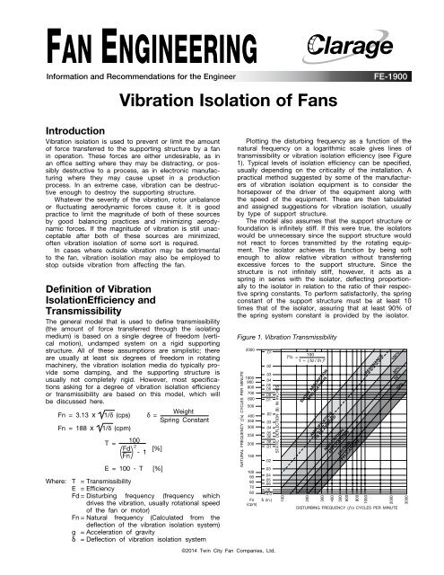
Plotting the disturbing frequency as a function <strong>of</strong> the<br />
natural frequency on a logarithmic scale gives lines <strong>of</strong><br />
transmissibility or vibration isolation efficiency (see Figure<br />
1). Typical levels <strong>of</strong> isolation efficiency can be specified,<br />
usually depending on the criticality <strong>of</strong> the installation. A<br />
practical method suggested by some <strong>of</strong> the manufacturers<br />
<strong>of</strong> vibration isolation equipment is to consider the<br />
horsepower <strong>of</strong> the driver <strong>of</strong> the equipment along with<br />
the speed <strong>of</strong> the equipment. These are then tabulated<br />
and assigned suggestions for vibration isolation, usually<br />
by type <strong>of</strong> support structure.<br />
The model also assumes that the support structure or<br />
foundation is infinitely stiff. If this were true, the isolators<br />
would be unnecessary since the support structure would<br />
not react to forces transmitted by the rotating equipment.<br />
The isolator achieves its function by being s<strong>of</strong>t<br />
enough to allow relative vibration without transferring<br />
excessive forces to the support structure. Since the<br />
structure is not infinitely stiff, however, it acts as a<br />
spring in series with the isolator, deflecting proportionally<br />
to the isolator in relation to the ratio <strong>of</strong> their respective<br />
spring constants. To perform satisfactorily, the spring<br />
constant <strong>of</strong> the support structure must be at least 10<br />
times that <strong>of</strong> the isolator, assuring that at least 90% <strong>of</strong><br />
the spring system constant is provided by the isolator.<br />
Figure 1. <strong>Vibration</strong> Transmissibility<br />
NATURAL FREQUENCY (ƒN) CYCLES PER MINUTE<br />
2000<br />
1000<br />
900<br />
800<br />
700<br />
600<br />
500<br />
400<br />
350<br />
300<br />
250<br />
200<br />
150<br />
100<br />
90<br />
80<br />
70<br />
60<br />
Fn<br />
(cpm)<br />
.01<br />
.02<br />
.03<br />
.04<br />
.05<br />
.06<br />
.08<br />
.01<br />
.02<br />
.03<br />
.04<br />
.05<br />
.06<br />
.08<br />
.01<br />
.02<br />
.03<br />
.04<br />
.05<br />
.06<br />
.08<br />
10.0<br />
δ (in.)<br />
STATIC DEFLECTION (δ) IN INCHES<br />
100<br />
100<br />
T% =<br />
1 – ( fd / fn ) 2<br />
SHOCK ABSORPTION<br />
APPLICATIONS<br />
200<br />
AMPLIFICATION<br />
TO BE AVOIDED<br />
300<br />
NON-CRITICAL<br />
APPLICATIONS<br />
400<br />
500<br />
600<br />
CRITICAL<br />
APPLICATIONS<br />
800<br />
1000<br />
RESONANCE<br />
2000<br />
DISTURBING FREQUENCY (ƒD) CYCLES PER MINUTE<br />
100%<br />
30%<br />
20%<br />
10%<br />
3000<br />
©2014 Twin City Fan Companies, Ltd.
Types <strong>of</strong> Support for<br />
<strong>Vibration</strong> <strong>Isolation</strong><br />
Equipment is supported on vibration isolation devices<br />
such as springs and pads in differing methods depending<br />
on the equipment mounted and rigidity <strong>of</strong> the supporting<br />
structure. Light duty equipment may be mounted<br />
directly on the devices, but <strong>of</strong>ten there is an intermediate<br />
supporting structure, which will be discussed here.<br />
In every case where equipment is mounted on isolators,<br />
the inlet and outlet must be flexibly connected to<br />
the ductwork. Ductwork which is rigidly connected will<br />
short circuit the vibration isolation and transmit vibration<br />
directly through the ductwork.<br />
1. <strong>Vibration</strong> <strong>Isolation</strong> Base — This type <strong>of</strong> base is usually<br />
supplied to either support a piece <strong>of</strong> equipment<br />
which has a frame which is not sufficiently stiff to be<br />
isolated independently, or to unitize the mounting <strong>of</strong><br />
a piece <strong>of</strong> equipment and the driver. It should be<br />
mentioned that bases are manufactured solely for the<br />
purpose <strong>of</strong> unitizing the mounting <strong>of</strong> a piece <strong>of</strong> equipment<br />
and the driver, and are not sufficiently rigid to<br />
be mounted on isolation. These are usually referred<br />
to as unitary bases, not vibration bases.<br />
The vibration base is constructed <strong>of</strong> structural<br />
members <strong>of</strong> sufficient depth to provide rigidity for the<br />
isolation installation, typically channel, I-beam or<br />
angle. If the motor is not mounted on the fan, built<br />
in slide rails or a slide base are usually provided as<br />
part <strong>of</strong> the base. To keep the height at a minimum,<br />
height saving brackets are also usually built into the<br />
base as a standard feature (see Figure 2).<br />
Figure 2. Typical <strong>Vibration</strong> <strong>Isolation</strong> Base<br />
3. Inertia Bases — (Concrete filled vibration isolation<br />
base) This type <strong>of</strong> base is used in the same sort <strong>of</strong><br />
installation as a vibration isolation base. The addition<br />
<strong>of</strong> concrete makes this base considerably stiffer, and<br />
the weight <strong>of</strong> the concrete in the base lowers the<br />
center <strong>of</strong> gravity <strong>of</strong> the installation, making it more<br />
stable on larger equipment. This type <strong>of</strong> base is preferable<br />
on fans that are coupled directly to the motor,<br />
as the stiffness helps to maintain coupling alignment.<br />
Some fan users prefer that this base be built with<br />
structural members stiff enough that the fan can be<br />
shipped and handled without the concrete in the<br />
base. Some also prefer a bottom pouring pan on this<br />
type <strong>of</strong> base for ease <strong>of</strong> installation (see Figure 4).<br />
Figure 4. Typical Inertia Base<br />
4. <strong>Isolation</strong> <strong>of</strong> <strong>Fans</strong> Mounted on Curbs — There are a<br />
few types <strong>of</strong> isolation equipment designed for mounting<br />
fans on curbs, usually custom designed for the<br />
application. Typically they are variations <strong>of</strong> the isolation<br />
base, sometimes incorporating the ro<strong>of</strong> curb itself<br />
into the structure (see Figure 5).<br />
Figure 5. Curb Mounted <strong>Vibration</strong> <strong>Isolation</strong><br />
for an Air Handling Unit<br />
2. <strong>Vibration</strong> <strong>Isolation</strong> Rails — <strong>Vibration</strong> isolation rails are<br />
sometimes employed in much the same capacity as<br />
the vibration isolation base, usually on smaller<br />
arrangement 9, 10 or 4 fans. They add stiffness to<br />
the mounting platform <strong>of</strong> the fan, and height saving<br />
brackets may be used if height needs to be kept to<br />
a minimum (see Figure 3).<br />
Figure 3. Typical <strong>Vibration</strong> <strong>Isolation</strong> Rails<br />
2 Fan Engineering FE-1900
<strong>Vibration</strong> Mounts<br />
There are several types <strong>of</strong> mounts typically used in fan<br />
vibration isolation installations, including pads, rubber-inshear<br />
mounts, and a variety <strong>of</strong> springs. The more common<br />
varieties will be discussed here.<br />
1. Rubber-in-Shear Isolators — Rubber-in-shear pads<br />
consist <strong>of</strong> two load plates <strong>of</strong> steel which are embedded<br />
in a rubber pad. The equipment to be isolated<br />
is bolted to the top load plate, and the bottom load<br />
plate is attached to the supporting structure. The rubber<br />
that is loaded in shear between the load plates<br />
provides the deflection that provides for the vibration<br />
isolation. The relatively small deflection provided by<br />
this type <strong>of</strong> pad makes it a good selection for vibration<br />
isolation on smaller, higher speed fans. Typical<br />
deflection is from 1 ⁄4" to 1 ⁄2" (see Figure 6).<br />
2. Open Springs — Open springs are the simplest <strong>of</strong> the<br />
spring mounts. They are required to be laterally stable<br />
without using a housing. This requires a horizontal<br />
stiffness to vertical stiffness ratio from about 0.75 to<br />
1.25. The deflection <strong>of</strong> the spring is at a rated load,<br />
and usually the spring provides approximately 50%<br />
overload capacity. That is, the spring will compress<br />
to completely closed at 150% <strong>of</strong> the design load.<br />
Leveling bolts are usually included in the springs to<br />
adjust the equipment to level when the springs are<br />
loaded. Often a neoprene pad is included between<br />
the bottom mounting plate and the supporting structure.<br />
Typical deflection is from 1" to 4". The greater<br />
deflection provides better vibration isolation efficiency<br />
for larger, slower moving fans (see Figure 7).<br />
3. Housed Springs — Housed springs work in the same<br />
way as open springs, but are contained in some type<br />
<strong>of</strong> enclosed housing. Often, this housing is telescoping,<br />
with rubber pads <strong>of</strong> some sort between the<br />
housing halves, providing some snubbing action for<br />
horizontal loads. To provide the necessary load carrying<br />
capability, there are sometimes multiple springs<br />
in the housing. The requirement for the horizontal to<br />
vertical stiffness ratio is usually not as high as for<br />
open springs. The spring does usually provide for<br />
50% overload capacity. Often a neoprene pad is<br />
included between the bottom mounting plate and the<br />
supporting structure. Typical deflection is from 1" to<br />
2" (see Figure 8).<br />
4. Restrained Springs — Usually this type <strong>of</strong> spring is<br />
the same in design as the open springs, but a housing<br />
or frame is included to restrain the vertical and/<br />
or horizontal motion <strong>of</strong> the spring. Springs that are<br />
vertically restrained are usually used in situations<br />
where the vertical loads may have upset conditions,<br />
such as wind loading. Horizontally restrained springs<br />
may have snubbing features to restrain horizontal<br />
loads in cases such as horizontal loads imposed on<br />
equipment start up (see Figure 9).<br />
5. Pads — Molded ribbed neoprene pads are used in<br />
some instances for isolation <strong>of</strong> smaller fans. Because<br />
<strong>of</strong> the extremely low deflection provided, these pads<br />
provide very little vibration isolation capacity. Typical<br />
deflection is about 1 ⁄16".<br />
Figure 6. Rubber-in-Shear<br />
Figure 8. Housed Spring<br />
Figure 10. Spring & RIS<br />
Hanger<br />
Figure 7. Open Spring<br />
Figure 9. Restrained Spring<br />
Figure 11. Use <strong>of</strong> Horizontal<br />
Thrust Restraint<br />
6. Hangers — Most <strong>of</strong> the isolators listed above have a<br />
similar hanger for suspending fans. Spring and rubber-in-shear<br />
(RIS) pads are used by themselves and<br />
in combination. Deflections and vibration isolation<br />
efficiencies are the same as when floor mounted<br />
when the same loads are imposed on the vibration<br />
isolation element (see Figure 10).<br />
7. Horizontal Thrust Restraints — Horizontal thrust<br />
restraints are used to prevent excessive motion <strong>of</strong><br />
fans due to aerodynamic force. Typically they are<br />
springs or spring/RIS pad combinations that are<br />
attached to both the fan discharge and the discharge<br />
duct. They are adjusted to prevent horizontal motion.<br />
To perform properly, they should be installed on the<br />
centerline <strong>of</strong> the thrust force.<br />
Fan Engineering FE-1900 3
Design Considerations for<br />
<strong>Vibration</strong> <strong>Isolation</strong> in<br />
Seismically Active Zones<br />
Special considerations must be taken when mounting<br />
fans on vibration isolation equipment in seismically active<br />
zones. Since the equipment is not rigidly mounted on<br />
these mounts, provision must be made to restrict lateral<br />
motion in the case <strong>of</strong> a seismic event. The support<br />
structure and anchor bolting must be designed to withstand<br />
this activity also.<br />
Seismic isolators are specially designed to withstand<br />
a specific lateral force. Usually a structural engineer then<br />
certifies the isolators for the load.<br />
The Uniform Building Code provides definitions <strong>of</strong> the<br />
seismic zones recognized in the United States. These<br />
zones, along with other factors (such as Importance<br />
Factors) determine the lateral force the vibration isolation<br />
system must withstand. The design <strong>of</strong> this type <strong>of</strong> installation<br />
and determination <strong>of</strong> necessary design force are<br />
usually made by a certified structural engineer.<br />
Figure 12. Uniform Building Code Seismic Zone Map <strong>of</strong> the United States<br />
ZONE 1 2A 2B 3 4<br />
Z 0.075 0.15 0.20 0.30 0.4<br />
Fp 0.188 0.375 0.50 0.75 1.0<br />
The zone factor (Z) is for use in the Static Lateral Force<br />
equation as found in the Uniform Building Code 1991<br />
Sect. 2312 and comparable publications such as BOCA<br />
1990 and national Building Code Sect. 1113.<br />
The zone factor is comparable to the effective peak<br />
acceleration in the applicable Seismic Zone, but is not<br />
the only factor.<br />
The complete Lateral Force equation Fp = ZICpWp (Ref.<br />
UBC 1991) is also dependent on other factors such as<br />
“Importance Factor and Occupancy Requirements.”<br />
These must be considered in determining the total static<br />
lateral force.<br />
It should also be noted that in some cases where wind<br />
loading conditions are higher, then the higher design factor<br />
governs.<br />
The Lateral Force equation can be taken one step further<br />
for simplification. The maximum values for “I” and “Cp”<br />
as published by UBC 1991 are substituted into the complete<br />
equation yielding the values for “Fp” based on the<br />
individual Seismic Zones.<br />
CLARAGE | WWW.CLARAGE.COM<br />
2335 Columbia Highway | Pulaski, TN 38478 | Phone: 931-363-2667 | Fax: 931-363-3155