Obelisk Sector Antenna for 2.4 and 5.8 GHz Wireless LAN - ATVA
Obelisk Sector Antenna for 2.4 and 5.8 GHz Wireless LAN - ATVA
Obelisk Sector Antenna for 2.4 and 5.8 GHz Wireless LAN - ATVA

Create successful ePaper yourself
Turn your PDF publications into a flip-book with our unique Google optimized e-Paper software.
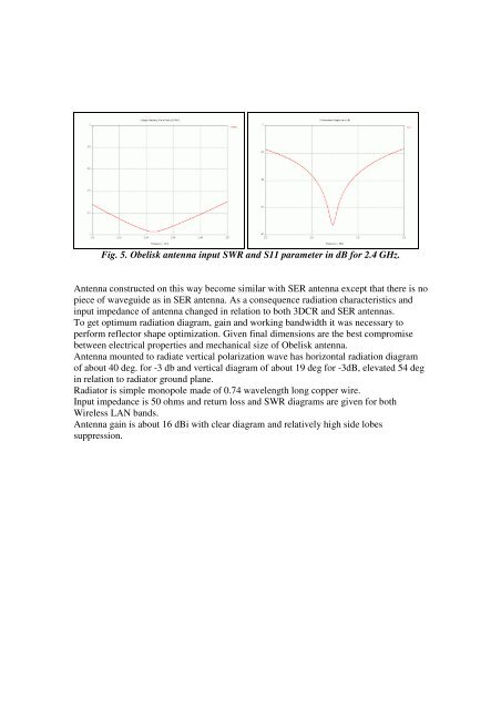
Fig. 5. <strong>Obelisk</strong> antenna input SWR <strong>and</strong> S11 parameter in dB <strong>for</strong> <strong>2.4</strong> <strong>GHz</strong>.<br />
<strong>Antenna</strong> constructed on this way become similar with SER antenna except that there is no<br />
piece of waveguide as in SER antenna. As a consequence radiation characteristics <strong>and</strong><br />
input impedance of antenna changed in relation to both 3DCR <strong>and</strong> SER antennas.<br />
To get optimum radiation diagram, gain <strong>and</strong> working b<strong>and</strong>width it was necessary to<br />
per<strong>for</strong>m reflector shape optimization. Given final dimensions are the best compromise<br />
between electrical properties <strong>and</strong> mechanical size of <strong>Obelisk</strong> antenna.<br />
<strong>Antenna</strong> mounted to radiate vertical polarization wave has horizontal radiation diagram<br />
of about 40 deg. <strong>for</strong> -3 db <strong>and</strong> vertical diagram of about 19 deg <strong>for</strong> -3dB, elevated 54 deg<br />
in relation to radiator ground plane.<br />
Radiator is simple monopole made of 0.74 wavelength long copper wire.<br />
Input impedance is 50 ohms <strong>and</strong> return loss <strong>and</strong> SWR diagrams are given <strong>for</strong> both<br />
<strong>Wireless</strong> <strong>LAN</strong> b<strong>and</strong>s.<br />
<strong>Antenna</strong> gain is about 16 dBi with clear diagram <strong>and</strong> relatively high side lobes<br />
suppression.