Drawing Requirements
Drawing Requirements
Drawing Requirements

You also want an ePaper? Increase the reach of your titles
YUMPU automatically turns print PDFs into web optimized ePapers that Google loves.
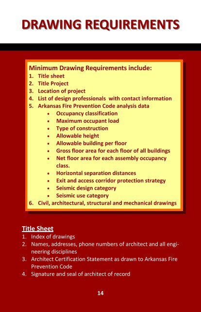
DRAWING REQUIREMENTS<br />
Minimum <strong>Drawing</strong> <strong>Requirements</strong> include:<br />
1. Title sheet<br />
2. Title Project<br />
3. Location of project<br />
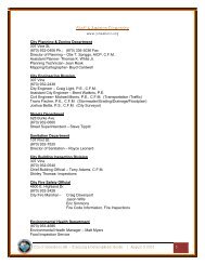
4. List of design professionals with contact information<br />
5. Arkansas Fire Prevention Code analysis data<br />
Occupancy classification<br />
Maximum occupant load<br />
Type of construction<br />
Allowable height<br />
Allowable building per floor<br />
Gross floor area for each floor of all buildings<br />
Net floor area for each assembly occupancy<br />
class.<br />
Horizontal separation distances<br />
Exit and access corridor protection strategy<br />
Seismic design category<br />
Seismic use category<br />
6. Civil, architectural, structural and mechanical drawings<br />
Title Sheet<br />
1. Index of drawings<br />
2. Names, addresses, phone numbers of architect and all engineering<br />
disciplines<br />
3. Architect Certification Statement as drawn to Arkansas Fire<br />
Prevention Code<br />
4. Signature and seal of architect of record<br />
14
DRAWING REQUIREMENTS<br />
Topographical Survey/Plot Plan<br />
1. Prepared by a Registered Land Surveyor<br />
2. Property lines, setbacks, right of ways, easements, existing utility<br />
locations<br />
Civil Site <strong>Drawing</strong>s<br />
1. Location of building, dimensioned<br />
2. Location of all improvements; walks, drives, out buildings,<br />
fences<br />
3. Site development details<br />
Landscape <strong>Drawing</strong>s<br />
1. Locations, size and number of all plants, trees, mulch/ground<br />
cover and lawn/sod area<br />
2. Plant schedule<br />
Fire Service Access/Life Safety <strong>Drawing</strong><br />
1. Show route of access on site for fire fighting apparatus<br />
2. Floor plan, indicate location of fire walls and required exits<br />
3. Detail of construction of fire walls with cooresponding U.L.<br />
number<br />
Demolition <strong>Drawing</strong>s<br />
1. Indicate existing building floor plan, clearly delineate items to<br />
be demolished and portions of building to remain<br />
Architectural <strong>Drawing</strong>s<br />
1. Floor plan<br />
Dimensioned to indicate room sizes, overall building size, and<br />
15
DRAWING REQUIREMENTS<br />
room names<br />
Room finish schedule<br />
2. Exterior elevations of building<br />
Note all exterior materials (i.e. brick, aluminum with glass,<br />
metal siding, etc.)<br />
Dimension building, canopy, and other appurtenances heights<br />
and size<br />
3. Roof plan<br />
Indicate slope of roof, roofing material, drains, gutters, rooftop<br />
equipment<br />
4. Building sections<br />
Indicate heights of ceilings, roofs, parapets, floor to floor<br />
height<br />
5. Wall sections<br />
Indicate makeup of each wall of building<br />
Clearly state each material, i.e. 2X4 wood studs, 5/8” gypsum<br />
board, R-19 Batt insulation, brick veneer, metal siding, etc.<br />
6. Stair sections<br />
Each stair configuration shall be shown<br />
Tread width, riser height, type construction<br />
Handrail details<br />
Structural <strong>Drawing</strong>s<br />
1. Foundation plan, dimensioned to correspond with floor plan<br />
Details of footings and foundations, including reinforced steel<br />
Floor construction noted, reinforcing<br />
2. Structural framing plan, dimensioned<br />
All framing members noted as to size<br />
Connection notations<br />
Decking size, pattern attachment<br />
16
DRAWING REQUIREMENTS<br />
3. Provide design load, capacity for foundation, floors, roof<br />
4. Details as required to explain structural intent<br />
MPE/Utilities Site Plan<br />
1. Locate all new and existing utility services<br />
2. Indicate site lighting<br />
Mechanical <strong>Drawing</strong>s<br />
1. H.V.A.C. floor plan with ductwork, grilles and registers located<br />
and sized<br />
2. Locate mechanical units, show size, physical requirements<br />
Plumbing <strong>Drawing</strong>s<br />
1. Plumbing floor plan, show fixtures, pipe locations and size for<br />
waste and supply lines<br />
2. Provide riser diagram for all piping<br />
Fire Protection <strong>Drawing</strong>s<br />
1. Sprinkler floor plan, indicate main runs, laterals, head locations<br />
and type<br />
2. Detail riser<br />
3. Prior to final acceptance shop drawings by licensed installer to<br />
be provided to building inspector<br />
Electrical <strong>Drawing</strong>s<br />
Electrical power plan, indicate panel location, size, panel riser,<br />
electrical outlets with wiring diagram showing circuits<br />
Electrical lighting plan, indicating switching and circuits<br />
Provide lighting fixture schedule<br />
17