Linear Link Temperature-Compensated Flowmeter Interface
Linear Link Temperature-Compensated Flowmeter Interface
Linear Link Temperature-Compensated Flowmeter Interface

Create successful ePaper yourself
Turn your PDF publications into a flip-book with our unique Google optimized e-Paper software.
<strong>Linear</strong> <strong>Link</strong> ®<br />
TCI<br />
<strong>Temperature</strong>-<strong>Compensated</strong><br />
<strong>Flowmeter</strong> <strong>Interface</strong><br />
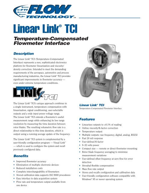
Description<br />
The <strong>Linear</strong> <strong>Link</strong> ® TCI (<strong>Temperature</strong>-<strong>Compensated</strong><br />
<strong>Interface</strong>) represents a new, sophisticated electronics<br />
platform for flowmeter linearization and viscosity/<br />
density correction. Intended to meet the demanding<br />
requirements of the aerospace, automotive and process<br />
manufacturing industries, the <strong>Linear</strong> <strong>Link</strong> ® TCI provides<br />
significant improvements in flowmeter accuracy —<br />
even under extreme temperature conditions.<br />
The <strong>Linear</strong> <strong>Link</strong> ® TCI’s unique approach combines in<br />
a single instrument, temperature compensation with<br />
linearization, signal conditioning, user-selectable<br />
outputs and a wide input power voltage range.<br />
The <strong>Linear</strong> <strong>Link</strong> ® TCI extends a flowmeter’s useful<br />
measurement range while enhancing its low range<br />
resolution by measuring the time duration between<br />
rotor blades. The resulting volumetric flow rate is a<br />
direct relationship to this time duration, which is<br />
output using a running average update of the frequency.<br />
The <strong>Linear</strong> <strong>Link</strong> ® TCI system is complemented by a<br />
user-friendly configuration program — Visual <strong>Link</strong> <br />
— which is used to configure the system and recall<br />
previously configured data.<br />
Benefits<br />
• Improved flowmeter accuracy<br />
• Elimination of multiple electronic devices<br />
• Reduced installation costs<br />
• Complete interchangeability of flowmeters<br />
• Stored calibration data supports ISO 9000 procedures<br />
• Easy interface to data acquisition system<br />
• Flow rate and temperature output available from<br />
one device<br />
<strong>Linear</strong> <strong>Link</strong> ® TCI<br />
<strong>Temperature</strong>-<strong>Compensated</strong> <strong>Flowmeter</strong> <strong>Interface</strong><br />
Features<br />
• <strong>Linear</strong>izes outputs to ±0.1% of reading<br />
• Online viscosity/K-factor correction<br />
• <strong>Temperature</strong> output<br />
• Multiple outputs: raw frequency, digital, analog, RS232<br />
• Fast 20 mS response<br />
• User-defined K-factor<br />
• 9–32 volts power<br />
• Compact size — remote or direct flowmeter mounting<br />
• Rotor blade frequency averaging to minimize<br />
measurement variations<br />
• User-defined offset frequency at zero flow for error<br />
detection<br />
• Strouhal-Roshko compensation<br />
• Mass flow rate output<br />
• Stores and recalls configuration and calibration data<br />
• User-friendly configuration software compatible with<br />
Windows ® 95 or newer operating system
How It Works<br />
Period Measurement with Averaging<br />
The <strong>Linear</strong> <strong>Link</strong> ® TCI uses a precision, period-based measurement method to measure the<br />
time duration between the turbine flowmeter rotor blades while providing a user-selectable<br />
speed of response. Period-based measurement enhances the resolution in the low flow<br />
range of the turbine meter where linearization is critical. One period can be measured to<br />
minimize response time or several periods can be averaged to smooth the output in a pulsating<br />
flow. A running average is updated every period with the least current frequency being discarded<br />
as the most current frequency is acquired. These features accurately extend the range<br />
capability equal to the repeatable range of the flowmeter.<br />
Compensation<br />
The <strong>Linear</strong> <strong>Link</strong> ® TCI’s innovative, temperature-compensated linearization technique<br />
reduces viscosity effects on K-factors by establishing fluid viscosity through online<br />
temperature measurements and proper calibration methods. <strong>Linear</strong>ization can be calculated by<br />
selecting either linear interpolation or cubic spline equations. Fast output is achieved through a matrix<br />
method which is indexed by a temperature/viscosity compensation input. The <strong>Linear</strong> <strong>Link</strong> ® TCI accepts a<br />
temperature signal from either an external or an internal RTD pickoff sensor. Up to 20 temperature data<br />
points can be entered to linearize the temperature sensor.<br />
Strouhal-Roshko Correlation<br />
The <strong>Linear</strong> <strong>Link</strong> ® TCI compensation technique utilizes equations<br />
developed to characterize flowmeters over a wide operating<br />
temperature. The Strouhal-Roshko correlation is used to improve<br />
flowmeter accuracy by making corrections for material expansion or<br />
contraction due to temperature variations. The Strouhal-Roshko<br />
correlation is utilized to improve flowmeter measurement accuracy<br />
when the actual temperature of the installation varies significantly<br />
from the calibration condition.<br />
Mass Flow Rate Output<br />
Density of the process fluid is established with a known temperature/density table which resides inside the <strong>Linear</strong> <strong>Link</strong> ® TCI.<br />
The temperature sensor signal is used by this table to determine the fluid density which, in turn, is multiplied by the<br />
volumetric flow rate to establish the mass flow rate. Up to 20 data points relating temperature to density can be entered.<br />
Typical Mounting Installations<br />
2X ø .312"<br />
(8mm)<br />
OUTPUTS<br />
<strong>Linear</strong> <strong>Temperature</strong> Analog<br />
<strong>Linear</strong> Flow Rate Analog<br />
Raw Flow Rate Frequency<br />
<strong>Linear</strong> Flow Rate Frequency<br />
RS232<br />
3.09"<br />
(78.5mm)<br />
1.55"<br />
(39.4mm)<br />
3.09"<br />
(78.5mm)<br />
<strong>Flowmeter</strong> & Flow Straightener<br />
6 = NEMA 4X<br />
Remote-mounted <strong>Linear</strong> <strong>Link</strong> ® TCI<br />
with analog temperature input in<br />
NEMA 4X enclosure with<br />
MS connectors<br />
4.75"<br />
(121mm)<br />
4.75"<br />
(121mm)<br />
OUTPUTS<br />
<strong>Linear</strong> <strong>Temperature</strong> Analog<br />
<strong>Linear</strong> Flow Rate Analog<br />
Raw Flow Rate Frequency<br />
<strong>Linear</strong> Flow Rate Frequency<br />
RS232<br />
2 x 1-11 1/2 NPT<br />
Pickoff with RTD<br />
XX DOWNSTREAM STRAIGHTENER XX<br />
P/N 44-B7734 - Y<br />
XX UPSTREAM STRAIGHTENER XX<br />
P/N 44-B7734 - Y<br />
<strong>Temperature</strong><br />
Transmitter<br />
<strong>Flowmeter</strong> & Flow Straightener with Integral RTD<br />
9 = Class I, Division 1, Groups A, B, C & D<br />
Explosion-proof housing with <strong>Linear</strong> <strong>Link</strong> ® TCI<br />
and RTD mounted integrally on top of flowmeter<br />
XX UPSTREAM STRAIGHTENER XX<br />
P/N 44-87734 - Y<br />
XX DOWNSTREAM STRAIGHTENER XX<br />
P/N 44-87734 - Y
Calibration <strong>Interface</strong><br />
The Visual <strong>Link</strong> software, with its intuitive,<br />
user-friendly PC interface, functions as a powerful<br />
calibration tool which allows the user to enter<br />
calibration and fluid property data, as well as<br />
configure the input and output signals. The<br />
software uses a toolbar with icons arranged in<br />
logical sequence to simplify the configuration of<br />
the TCI. The calibration and configuration data is<br />
stored in the <strong>Linear</strong> <strong>Link</strong> ® TCI and can be recalled<br />
and viewed with the Visual <strong>Link</strong> software, allowing<br />
the user to have a record of the previous calibration<br />
along with a history of the instrument.<br />
The <strong>Linear</strong> <strong>Link</strong> ® TCI is configured by reading in<br />
calibration and fluid property data from a flowmeter<br />
calibration electronic data file, or entering the data<br />
manually. The date of the most recent calibration,<br />
the date of the next calibration, and comments<br />
may be stored. This feature supports ISO 9000<br />
documentation procedures.<br />
Main Menu<br />
Data for kinematic viscosity and fluid density for<br />
the liquid being measured can also be selected<br />
from a library file or entered manually. The system<br />
utilizes either an Andrade or an ASTM correlation to<br />
perform viscosity calculation. <strong>Flowmeter</strong> calibration<br />
files can be read and displayed simultaneously to<br />
assist with editing a Universal Viscosity Curve. The<br />
data can then be displayed on a graph in real-time<br />
for verification, or edited as needed for optimum<br />
characterization of the flowmeter.<br />
The temperature sensor data is stored in a table<br />
which includes 2 endpoints for zero and span, or<br />
multiple points for linearization, up to a maximum<br />
of 20 points. The tables can be configured for either<br />
a temperature transmitter or direct RTD sensor. The<br />
temperature sensor data can be edited and displayed<br />
graphically in real-time.<br />
Fluid Viscosity Table<br />
Visual <strong>Link</strong> is a calibration tool which also<br />
provides fluid viscosity and density profiles, unit<br />
conversion for volume, viscosity and temperature,<br />
as well as other useful functions which support<br />
flow measurement. The software is designed to<br />
operate on any system that supports a Windows ® 95<br />
or newer operating system. If using Windows ® 95,<br />
98 or Me European versions, please consult the<br />
factory.<br />
Universal Viscosity Curve
Specifications<br />
Model # Specifications<br />
Code<br />
Input Power<br />
24 VDC nominal 3 9–32 VDC, 0.1 amps max.,<br />
900 mW @ 9 VDC (excluding 4–20 mA)<br />
24 VDC nominal 5 10–32 VDC, 0.1 amps max.,<br />
1.0 W @ 10 VDC (excluding 4–20 mA)<br />
(required for I.S. Approval)<br />
Note: 15–32 VDC power required for 4–20 mA output.<br />
<strong>Flowmeter</strong> Input Type<br />
Magnetic<br />
A<br />
Frequency range:<br />
1 Hz – 4 kHz<br />
Impedance:<br />
Greater than 5 K ohms<br />
Sensitivity:<br />
20 mV p-p<br />
Pulse<br />
B<br />
Frequency range:<br />
1 Hz to 4 kHz<br />
Impedance:<br />
5.8 K ohms to +5 VDC<br />
Schmitt Trigger Buffer<br />
Voltage (STB):<br />
Low: 0–1 VDC; High: 4–5 VDC<br />
Input Maximum:<br />
0–10 VDC, 1 Hz–4 kHz<br />
RF<br />
C<br />
Frequency range:<br />
5–3500 Hz<br />
Inductance:<br />
1 mH<br />
Oscillator frequency:<br />
45–55 kHz<br />
<strong>Temperature</strong> Input Type<br />
RTD 0<br />
<strong>Temperature</strong> range: -148° F to +752° F (-100° C to +400° C)<br />
Type:<br />
100 ohm Platinum<br />
Voltage 1 0–10 VDC<br />
0 VDC = Minimum <strong>Temperature</strong><br />
10 VDC = Maximum <strong>Temperature</strong><br />
Current 2 4–20 mA<br />
4 mA = Minimum <strong>Temperature</strong><br />
20 mA = Maximum <strong>Temperature</strong><br />
Voltage 3 0–5 VDC<br />
0 VDC = Minimum <strong>Temperature</strong><br />
5 VDC = Maximum <strong>Temperature</strong><br />
<strong>Linear</strong>ization<br />
<strong>Flowmeter</strong> K-factor<br />
Number of Points: 2–100<br />
Interpolation Method:<br />
<strong>Linear</strong> or cubic spline (selectable)<br />
Correlation:<br />
Strouhal-Roshko (per NIST publication)<br />
<strong>Temperature</strong><br />
Number of Points: 2–20<br />
Interpolation Method:<br />
<strong>Linear</strong><br />
Viscosity<br />
Number of Points: 2–20<br />
Interpolation Method:<br />
<strong>Linear</strong><br />
Correlation:<br />
ASTM D341-93, Andrades Equation or user-defined<br />
Specifications<br />
Density<br />
Number of Points: 2–20<br />
Interpolation Method:<br />
<strong>Linear</strong><br />
Outputs<br />
Frequency (Flow Rate)<br />
Flow Rate Raw Frequency:<br />
0–5 VDC pulse<br />
Flow Rate <strong>Linear</strong>ized Frequency:<br />
0–5 VDC pulse (1–3500 Hz)<br />
Impedance:<br />
2.2 K ohms<br />
Transmission Distance:<br />
250 ft. maximum<br />
Analog Voltage (Flow Rate & <strong>Temperature</strong>) 0–10 VDC or 0–5 VDC (user-specified/<br />
factory-set)<br />
<strong>Linear</strong>ized, scaled zero offset:<br />
Less than 10 mV<br />
Analog Current (Flow Rate & <strong>Temperature</strong>) 4–20 mA<br />
<strong>Linear</strong>ized, scaled maximum load: R load = (supply voltage – 4)/0.02<br />
RS232 (Volume/Mass Flow, <strong>Temperature</strong>, Other)<br />
Baud Rate: 9600, 19200, 38400, 56800<br />
Update Rate:<br />
0.5/sec., 1.0/sec., or 2.0/sec.<br />
Data Bits: 8<br />
Stop Bit: 1<br />
Parity:<br />
None<br />
Performance<br />
Accuracy<br />
<strong>Linear</strong>ized Frequency:<br />
0.1% of reading or better<br />
<strong>Linear</strong>ized Analog:<br />
0.1% of full scale or better<br />
RTD:<br />
±1° C (does not include RTD uncertainty)<br />
Analog Input (<strong>Temperature</strong>):<br />
12 Bit A/D<br />
<strong>Linear</strong>ization Latency<br />
9–20 mS + period of input<br />
Environment<br />
<strong>Temperature</strong><br />
Operating: -40° F to +185° F (-40° C to +85° C)<br />
Storage: -67° F to +257° F (-55° C to +125° C)<br />
Humidity<br />
0 to 85% RH non-condensing<br />
Enclosure NEMA 4X; Class I, Division 1 & 2,<br />
Group A, B, C, & D; dust-tight<br />
aluminum<br />
Communication<br />
<strong>Interface</strong><br />
RS232, serial USART connection<br />
to personal computer (with serial cable)<br />
Baud<br />
Output: 9600, 19200, 38400, 56800<br />
Programming:<br />
19.2 K<br />
Data Bits: 8<br />
Stop Bit: 1<br />
Parity:<br />
None<br />
Approvals<br />
Intrinsically Safe (pending)<br />
CE<br />
FM, CSA, CENELEC EEx ia IIC T4<br />
EN50081-2, EN50082-2, EN55011<br />
Model Numbering System<br />
L N T – – –<br />
–<br />
Basic Model No.<br />
Power<br />
3 = 9–32 VDC<br />
5 = 12-32 VDC<br />
(Option 5 is low power consumption<br />
for intrinsically safe approval)<br />
<strong>Flowmeter</strong> Input<br />
A = Magnetic<br />
B = Pulse<br />
C = RF Carrier<br />
<strong>Temperature</strong> Input<br />
0 = RTD<br />
1 = 0–10 VDC<br />
2 = 4–20 mA<br />
3 = 0–5 VDC<br />
Specifications are for reference only and are subject to change without notice.<br />
Approvals<br />
Blank = No Approvals<br />
CE = CE Mark<br />
CIS = CE & Intrinsically Safe (pending)<br />
IS = Intrinsically Safe, FM, CSA & CENELEC EEx ia IIC T4 (pending)<br />
_ _ _ = Three-Digit Special Code (factory-assigned)<br />
Enclosure<br />
– 0 = No Enclosure (n/a with pickoff version)<br />
B6 = NEMA 4X with 1/2" NPT Conduit Connections<br />
B7 = NEMA 4X with MS Connectors (MS3106)<br />
– 9 = Class I, Division 1, Groups A, B, C & D<br />
A7 = Dust-tight Alumimum with MS Connectors<br />
Outputs (<strong>Linear</strong>ized & <strong>Compensated</strong>)<br />
F1 = Frequency Output (0–5 VDC) Square Wave for Flow Rate<br />
V1 = Analog Voltage (0–10 VDC) for Flow Rate and <strong>Temperature</strong><br />
V2 = Analog Voltage (0–5 VDC) for Flow Rate and <strong>Temperature</strong><br />
MA = Analog Current (4–20 mA) for Flow Rate and <strong>Temperature</strong><br />
Note: Options V1, V2 and MA include flowmeter frequency output<br />
Local Representative:<br />
8930 S. Beck Avenue, Ste 107, Tempe, Arizona 85284 USA<br />
Tel: (480) 240-3400 • Fax: (480) 240-3401 • Toll Free: 1-800-528-4225<br />
E-mail: ftimarket@ftimeters.com • Web: www.ftimeters.com<br />
Trademarks are the property of their respective companies.<br />
DB 62877 Rev E © 2000 FTI Flow Technology, Inc.<br />
Printed in USA