Infrared Receiver Control Receiver Module IRM ... - Everlight.com
Infrared Receiver Control Receiver Module IRM ... - Everlight.com
Infrared Receiver Control Receiver Module IRM ... - Everlight.com

You also want an ePaper? Increase the reach of your titles
YUMPU automatically turns print PDFs into web optimized ePapers that Google loves.
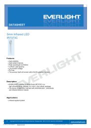
<strong>Infrared</strong> <strong>Receiver</strong> <strong>Control</strong><br />
<strong>Receiver</strong> <strong>Module</strong><br />
<strong>IRM</strong>-36xxM series<br />
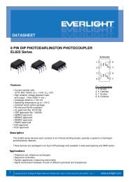
Features<br />
High protection ability against EMI<br />
Circular lens for improved reception characteristics<br />
Available for various carrier frequencies<br />
Min burst length: 6 cycles<br />
Min gap length: 10 cycles<br />
Suitable for continuous code<br />
Low operating voltage and low power consumption<br />
Optimized immunity against TFT backlight interferences<br />
High immunity against ambient light<br />
Long reception range<br />
High sensitivity<br />
Pb free and RoHS <strong>com</strong>pliant<br />
1 2 3<br />
Description<br />
The <strong>IRM</strong>-36xxM series devices are miniature type<br />
infrared receivers which have been developed and<br />
designed by using the latest IC technology, specially<br />
optimized to suppress interferences from TFT<br />
backlight.<br />
The photo diode and preamplifier are assembled onto<br />
a lead frame and molded into an epoxy package<br />
which operates as an IR filter.<br />
The demodulated output signal can directly be<br />
decoded by a microprocessor.<br />
Pin Configuration<br />
1. OUT<br />
2. GND<br />
3. V CC<br />
Applications<br />
•AV equipment such as TV, VCR, DVD, CD, MD, etc.<br />
•Short pause time protocols<br />
•Toy applications<br />
•CATV set top boxes<br />
•Multi-media Equipment<br />
•Other devices using IR remote control<br />
Application Circuit<br />
Block Diagram<br />
The RC Filter must be connected as close as possible to<br />
Vcc and GND pins.<br />
<strong>Everlight</strong> Electronics Co., Ltd. 1 http://www.everlight.<strong>com</strong><br />
Document No:DMO-0000128 Rev.3 January 25, 2011<br />
Revision : 3<br />
LifecyclePhase:<br />
Release Date:2011-03-07 10:36:36.0<br />
Expired Period: Forever
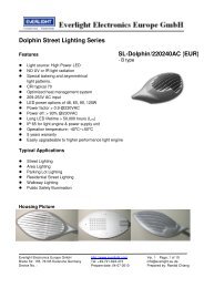
<strong>Infrared</strong> <strong>Receiver</strong> <strong>Control</strong><br />
<strong>Receiver</strong> <strong>Module</strong><br />
<strong>IRM</strong>-36xxM series<br />
Parts Table<br />
Model No.<br />
<strong>IRM</strong>-3636M<br />
<strong>IRM</strong>-3638M<br />
<strong>IRM</strong>-3640M<br />
<strong>IRM</strong>-3656M<br />
Carrier Frequency<br />
36 kHz<br />
38 kHz<br />
40 kHz<br />
56 kHz<br />
Package Dimensions<br />
(Dimensions in mm)<br />
<strong>Everlight</strong> Electronics Co., Ltd. 2 http://www.everlight.<strong>com</strong><br />
Document No:DMO-0000128 Rev.3 January 25, 2011<br />
Revision : 3<br />
LifecyclePhase:<br />
Release Date:2011-03-07 10:36:36.0<br />
Expired Period: Forever
<strong>Infrared</strong> <strong>Receiver</strong> <strong>Control</strong><br />
<strong>Receiver</strong> <strong>Module</strong><br />
<strong>IRM</strong>-36xxM series<br />
Absolute Maximum Ratings (T a =25°C)<br />
Parameter Symbol Rating Unit<br />
Supply Voltage Vcc 6 V<br />
Operating Temperature Topr -20 ~ +80 <br />
Storage Temperature Tstg -40 ~ +85 <br />
Soldering Temperature *1 Tsol 260 <br />
*1 4mm from mold body for less than 10 seconds<br />
Electro-Optical Characteristics (Ta=25, Vcc=3V)<br />
Parameter Symbol MIN. TYP. MAX. Unit Condition<br />
Current consumption Icc --- 0.4 0.6 mA No input signal<br />
Supply voltage V CC 2.7 - 5.5 V<br />
Peak wavelength λ p --- 940 --- nm<br />
Reception range<br />
L 0 14 --- ---<br />
m<br />
L 45 6 --- ---<br />
Half angle(horizontal) φ h --- ±35 --- deg<br />
See chapter<br />
‚Test method’<br />
Half angle(vertical) φ v --- ±35 --- deg<br />
High level pulse width T H 450 --- 700 μs<br />
Low level pulse width T L 500 --- 750 μs<br />
Test signal<br />
according to<br />
figure 1<br />
High level output voltage V OH Vcc-0.4 --- --- V I SOURCE 1μA<br />
Low level output voltage V OL --- 0.2 0.5 V I SINK 2mA<br />
Internal pull up resistor R PU 85 100 115 kΩ<br />
<strong>Everlight</strong> Electronics Co., Ltd. 3 http://www.everlight.<strong>com</strong><br />
Document No:DMO-0000128 Rev.3 January 25, 2011<br />
Revision : 3<br />
LifecyclePhase:<br />
Release Date:2011-03-07 10:36:36.0<br />
Expired Period: Forever
<strong>Infrared</strong> <strong>Receiver</strong> <strong>Control</strong><br />
<strong>Receiver</strong> <strong>Module</strong><br />
<strong>IRM</strong>-36xxM series<br />
Test method<br />
The specified electro-optical characteristics are valid under the following conditions.<br />
1. Measurement environment<br />
A place without extreme light reflections.<br />
2. External light<br />
The environment contains an ordinary, white fluorescent lamp without high frequency modulation. The<br />
color temperature is 2856K and the illumination at the IR receiver is less than 10 Lux (Ev10Lux).<br />
3. Standard transmitter<br />
The test transmitter is calibrated by using the circuit shown in figure 2. The radiation intensity of the<br />
transmitter is adjusted until Vo=400mVp-p. Both, the test transmitter and the photo diode, have a peak<br />
wavelength of 940nm. The photo diode for calibration is PD438B (λp=940nm, Vr=5V).<br />
4. The measurement system is shown in Fig.-3<br />
Fig.-1 Transmitter Wave Form<br />
D.U.T output Pulse<br />
Fig.-2 standard transmitter calibration Fig.-3 Measuring System<br />
<strong>Everlight</strong> Electronics Co., Ltd. 4 http://www.everlight.<strong>com</strong><br />
Document No:DMO-0000128 Rev.3 January 25, 2011<br />
Revision : 3<br />
LifecyclePhase:<br />
Release Date:2011-03-07 10:36:36.0<br />
Expired Period: Forever
<strong>Infrared</strong> <strong>Receiver</strong> <strong>Control</strong><br />
<strong>Receiver</strong> <strong>Module</strong><br />
<strong>IRM</strong>-36xxM series<br />
Typical Electro-Optical Characteristic Curves<br />
<strong>Everlight</strong> Electronics Co., Ltd. 5 http://www.everlight.<strong>com</strong><br />
Document No:DMO-0000128 Rev.3 January 25, 2011<br />
Revision : 3<br />
LifecyclePhase:<br />
Release Date:2011-03-07 10:36:36.0<br />
Expired Period: Forever
<strong>Infrared</strong> <strong>Receiver</strong> <strong>Control</strong><br />
<strong>Receiver</strong> <strong>Module</strong><br />
<strong>IRM</strong>-36xxM series<br />
Code information<br />
Protocol Suitable Protocol Suitable<br />
JVC Yes RCA Yes<br />
Matsushita Yes Sharp Yes<br />
Mitsubishi Yes Sony 12 Bit Yes<br />
NEC Yes Sony 15 Bit No<br />
RC5 Yes Sony 20Bit No<br />
RC6 Yes Toshiba Yes<br />
RCMM Yes Zenith Yes<br />
RCS-80 Yes Continuous Code Yes<br />
Device Marking<br />
Notes<br />
1 denotes Year code<br />
2 denotes Month code<br />
3 denotes Device number<br />
4 denotes Carrier frequency (2: 36KHz, 4: 38KHz 5: 40KHz 7:56KHz)<br />
<strong>Everlight</strong> Electronics Co., Ltd. 6 http://www.everlight.<strong>com</strong><br />
Document No:DMO-0000128 Rev.3 January 25, 2011<br />
Revision : 3<br />
LifecyclePhase:<br />
Release Date:2011-03-07 10:36:36.0<br />
Expired Period: Forever
<strong>Infrared</strong> <strong>Receiver</strong> <strong>Control</strong><br />
<strong>Receiver</strong> <strong>Module</strong><br />
<strong>IRM</strong>-36xxM series<br />
Packing Quantity<br />
1500 pcs / Box<br />
10 Boxes / Carton<br />
<strong>Everlight</strong> Electronics Co., Ltd. 7 http://www.everlight.<strong>com</strong><br />
Document No:DMO-0000128 Rev.3 January 25, 2011<br />
Revision : 3<br />
LifecyclePhase:<br />
Release Date:2011-03-07 10:36:36.0<br />
Expired Period: Forever
<strong>Infrared</strong> <strong>Receiver</strong> <strong>Control</strong><br />
<strong>Receiver</strong> <strong>Module</strong><br />
<strong>IRM</strong>-36xxM series<br />
DISCLAIMER<br />
1. Above specification may be changed without notice. EVERLIGHT will reserve authority on material<br />
change for above specification.<br />
2. When using this product, please observe the absolute maximum ratings and the instructions for use<br />
outlined in these specification sheets. EVERLIGHT assumes no responsibility for any damage resulting<br />
from use of the product which does not <strong>com</strong>ply with the absolute maximum ratings and the instructions<br />
included in these specification sheets.<br />
3. These specification sheets include materials protected under copyright of EVERLIGHT. Reproduction in<br />
any form is prohibited without the specific consent of EVERLIGHT.<br />
<strong>Everlight</strong> Electronics Co., Ltd. 8 http://www.everlight.<strong>com</strong><br />
Document No:DMO-0000128 Rev.3 January 25, 2011<br />
Revision : 3<br />
LifecyclePhase:<br />
Release Date:2011-03-07 10:36:36.0<br />
Expired Period: Forever