NJR2633_34_35_36_37_39E LNB.pdf - New Era Systems, Inc
NJR2633_34_35_36_37_39E LNB.pdf - New Era Systems, Inc
NJR2633_34_35_36_37_39E LNB.pdf - New Era Systems, Inc

Create successful ePaper yourself
Turn your PDF publications into a flip-book with our unique Google optimized e-Paper software.
External Reference<br />
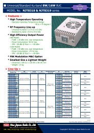
Ku band PLL <strong>LNB</strong><br />
Model No. <strong>NJR2633</strong>E<br />
Model No. NJR26<strong>34</strong>E<br />
Model No. NJR26<strong>35</strong>E<br />
Model No. NJR26<strong>36</strong>E<br />
Model No. NJR26<strong>37</strong>E<br />
Model No. NJR26<strong>39E</strong><br />
Specifications<br />
Rev.05M Febeuary 18, 2003<br />
Copyright 2003<br />
<strong>New</strong> Japan Radio Co., Ltd.<br />
Microwave Components Division<br />
-Notice of Proprietary Information-<br />
This documents and its contents are proprietary to <strong>New</strong> Japan Radio Co., Ltd.<br />
This publication and its contents may not be reproduced or distributed for any<br />
other purpose without the written permission of <strong>New</strong> Japan Radio Co., Ltd.<br />
1<br />
Rev.05M_Feb.18, 2003_<strong>NJR2633</strong>E<strong>34</strong>E/<strong>35</strong>E/<strong>36</strong>E/<strong>37</strong>E/<strong>39E</strong>
1. Scope<br />
This specification defines the low noise and block downconverter intended for the satellite data communication downlink application<br />
in the Ku-Band.<br />
This <strong>LNB</strong> has a combined 3-stage HEMT Amplifier and Block Down Converter with a Phase Locked Local, which is constituted<br />
with a VCO, SPD (Sampling Phase Detector), Loop Filter and Reference Recovery VCXO providing low phase noise.<br />
This <strong>LNB</strong> has type F-female IF output connector.<br />
All specifications shall apply throughout the full range of the specified environmental conditions unless otherwise specified.<br />
2. Electrical Specifications<br />
# Item Specification<br />
2-1. Input Frequency Band 11.45 to 11.95 GHz <br />
12.20 to 12.70 GHz <br />
11.70 to 12.20 GHz <br />
12.25 to 12.75 GHz <br />
10.95 to 11.70 GHz <br />
11.20 to 11.70 GHz <br />
2-2. Input Waveguide Flange WR 75<br />
2-3. Input V.S.W.R. 2.5 : 1 typ.<br />
2-4. Noise figure (Ta: +25 C) 0.8 dB typ. 1.2 dB max.<br />
2-5. Output Frequency 950 to 1,450 MHz<br />
<br />
950 to 1,700 MHz<br />
<br />
2-6. Conversion Gain (Ta: +25 C) 55 dB min. 60 dB typ.<br />
2-7. Conversion Gain Variation (Ta: +25 C) 2.0 dB max.<br />
in any 50 MHz segment over the frequency band.<br />
2-8. Output Power for 1 dB Gain Compression 0 dBm min.<br />
2-9. Intermodulation Products<br />
45 dBc min<br />
(3rd order Intermodulation rejection with two RF<br />
input carriers separated by 10 MHz, -10 dBm IF<br />
Output Power)<br />
2-10. Local Oscillator Leakage Levels -25 dBm max. at the IF Output Connector.<br />
-60 dBm max. at the RF Input Flange.<br />
2-11. Local Oscillator Frequency 10.50 GHz nom. <br />
11.25 GHz nom. <br />
10.75 GHz nom. <br />
11.30 GHz nom. <br />
10.00 GHz nom. <br />
10.25 GHz nom. <br />
2-12. Phase Noise (SSB) -75 dBc/Hz at 100 Hz<br />
-80 dBc/Hz at 1 kHz<br />
-90 dBc/Hz at 10 kHz<br />
-110 dBc/Hz at 100 kHz<br />
*Depend on Phase Noise of the External Reference.<br />
2-13. External Reference Input Frequency 10 MHz nom.<br />
2-14. External Reference Input Power -10 to 0 dBm (75 ohm) @IF Output connector<br />
2-15. External Reference Input Port IF Output Connector<br />
(Combine Reference with IF Signal)<br />
2<br />
Rev.05M_Feb.18, 2003_<strong>NJR2633</strong>E<strong>34</strong>E/<strong>35</strong>E/<strong>36</strong>E/<strong>37</strong>E/<strong>39E</strong>
# Item Specification<br />
2-16. External Reference Phase Noise -1<strong>35</strong> dBc/Hz at 100 Hz<br />
-143 dBc/Hz at 1 kHz<br />
-145 dBc/Hz at 10 kHz<br />
(Input Condition)<br />
2-17. Spurious a) -140 dBm max.<br />
At input, fixed frequency spur, unrelated to test CW signal.<br />
(Measured at specified IF band ; 950 to 1,450 or 1,700 MHz)<br />
b) -50 dBc max.<br />
With test CW signal -10 dBm IF output<br />
(Measured at specified IF band ; 950 to 1,450 or 1,700 MHz)<br />
2-18. Image Rejection 45 dB min.<br />
2-19. Output V.S.W.R. (75 ohm) 2.3 : 1 max.<br />
2-20. Input Voltage +15 to +24 V DC<br />
2-21. Current Drain 380 mA typ. 400 mA max.<br />
3. Environmental Specifications<br />
# Item Specification<br />
3-1. Operating Temperature Range -40 to +60 C<br />
3-2. Storage Temperature Range -40 to +80 C<br />
3-3. Humidity 100 % Rh max.<br />
3-4. Vibration 5 G ( f : 50 Hz, T : 5 min. Direction : X,Y,Z )<br />
3-5. Shock 15 G ( Direction : X,Y,Z )<br />
4. Absolute Maximum Rating<br />
# Item Specification<br />
4-1 RF Input Power -10 dBm (@ CW)<br />
4-2. Supply Voltage +28 Vdc<br />
3<br />
Rev.05M_Feb.18, 2003_<strong>NJR2633</strong>E<strong>34</strong>E/<strong>35</strong>E/<strong>36</strong>E/<strong>37</strong>E/<strong>39E</strong>
5. Outline Drawing<br />
Unit : mm<br />
4<br />
Rev.05M_Feb.18, 2003_<strong>NJR2633</strong>E<strong>34</strong>E/<strong>35</strong>E/<strong>36</strong>E/<strong>37</strong>E/<strong>39E</strong>