User manual for W15 sampling valve - Fagerberg
User manual for W15 sampling valve - Fagerberg
User manual for W15 sampling valve - Fagerberg

Create successful ePaper yourself
Turn your PDF publications into a flip-book with our unique Google optimized e-Paper software.
MN-000000 <strong>User</strong> <strong>manual</strong> <strong>for</strong> <strong>W15</strong> <strong>valve</strong><br />
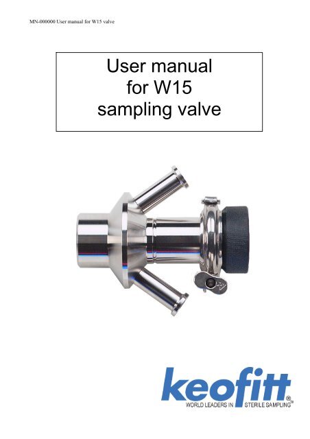
<strong>User</strong> <strong>manual</strong><br />
<strong>for</strong> <strong>W15</strong><br />
<strong>sampling</strong> <strong>valve</strong>
Contents:<br />
Contents:...........................................................................................................................................1<br />
Introduction: .....................................................................................................................................2<br />
Presentation: .....................................................................................................................................2<br />
Restrictions:...................................................................................................................................2<br />
Valve function ...............................................................................................................................2<br />
<strong>W15</strong> Item no.: 860001 and 860009.....................................................................................................3<br />
Mounting instructions ..........................................................................................................................4<br />
Location:........................................................................................................................................4<br />
Be<strong>for</strong>e welding: .............................................................................................................................4<br />
Welding instructions:........................................................................................................................5<br />
Type T: ..........................................................................................................................................5<br />
Type P: ..........................................................................................................................................5<br />
Block diagram <strong>for</strong> installing <strong>W15</strong> <strong>valve</strong>..............................................................................................6<br />
Keofitt <strong>valve</strong> type P (Pipe): ..............................................................................................................6<br />
Keofitt <strong>valve</strong> type T (tank): ..............................................................................................................6<br />
Keofitt <strong>valve</strong> Varivent Ø68: .............................................................................................................7<br />
Keofitt <strong>valve</strong> type C, 3” Clamp connection:.....................................................................................7<br />
Everyday use of the <strong>valve</strong> ....................................................................................................................8<br />
Sterilisation:......................................................................................................................................8<br />
Sampling:..........................................................................................................................................8<br />
Maintenance:.....................................................................................................................................9<br />
Instructions on replacing PTFE membrane: .....................................................................................9<br />
Available <strong>valve</strong> heads: .......................................................................................................................10<br />
Item no. 865541 - Valve Head <strong>for</strong> <strong>W15</strong> Type H ............................................................................10<br />
Item no.: 865544 - Valve Head <strong>for</strong> <strong>W15</strong> Type N..........................................................................10<br />
Membrane <strong>for</strong> <strong>W15</strong> – item no. 860055..............................................................................................11<br />
Technical Specification: .................................................................................................................11<br />
- 1 -
Introduction:<br />
Manufacturer:<br />
Keofitt a/s,<br />
Hans Egedes Vej 19<br />
5210 Odense NV<br />
Denmark<br />
Presentation:<br />
Sampling <strong>valve</strong>, Type: <strong>W15</strong><br />
Year of production: 2002<br />
The Keofitt <strong>sampling</strong> <strong>valve</strong> is a <strong>valve</strong> which can be readily sterilised and which meets both hygienic<br />
and production requirements. This means that an effective cleaning and sterilisation of the <strong>sampling</strong><br />
<strong>valve</strong> can be carried out between random samples independently of the course of the production<br />
process.<br />
The Keofitt <strong>W15</strong> <strong>valve</strong> is 3-A certified. 3-A Sanitary Standard is an American standard which is<br />
normative <strong>for</strong> a component’s ease of cleaning and sterilisation. The standard ensures optimum<br />
conditions <strong>for</strong> food products which may come into contact with the component in question.<br />
The <strong>valve</strong> is used in a wide range of business areas where <strong>sampling</strong> high viscosity products, such as<br />
dairies, yogurt, fruit and marmalade industries.<br />
Warning! During sterilisation with steam the <strong>valve</strong> will become hot, and care should thus be taken<br />
when handling the <strong>valve</strong>.<br />
Restrictions:<br />
• The <strong>valve</strong> cannot be used <strong>for</strong> vacuum since the membrane will be sucked hard into the seat.<br />
• The <strong>W15</strong> and W25 <strong>valve</strong>s are only available with PTFE membranes.<br />
• The PTFE membrane resists most CIP fluids and very high steam temperatures.<br />
• <strong>W15</strong> is only available with Clamp on the inlet /outlet connections.<br />
• For best results it is best to leave the steam hose constantly connected to the <strong>valve</strong>. Detaching<br />
the hose risks air contamination and makes the sterilisation process unnecessarily complicated.<br />
Valve function<br />
The <strong>valve</strong> is designed to regularly take representative random samples in the production process.<br />
The <strong>valve</strong> is there<strong>for</strong>e designed such that effective cleaning, sterilisation and <strong>sampling</strong> can be<br />
carried out regularly without interrupting the production process.<br />
Sterilisation is carried out by supplying steam through the upper of the <strong>valve</strong>’s two hose pieces. It is<br />
the perfect, hygienic design in the inner part of the <strong>valve</strong> which enables absolute sterilisation in a<br />
closed state.<br />
Note!<br />
The membrane functions both as a dynamic packing in the <strong>valve</strong> seat and as a hygienic,<br />
static packing against the <strong>valve</strong> body.<br />
- 2 -
<strong>W15</strong> Item no.: 860001, 860003, 860009 and 860011<br />
Valve body W 15 Type H<br />
Item no.: 860001<br />
Valve body W 15, Varivent Ø68<br />
Item no.: 860009<br />
Valve body W 15 Type P<br />
Item no.: 860011<br />
Valve body W 15 Type C<br />
Item no.: 860003<br />
Welding:<br />
available <strong>for</strong> tank or pipe.<br />
Port Connection: Varivent ø68mm and 3” clamp connection.<br />
Use <strong>for</strong>:<br />
Sample marmalade, yoghurt and fruit products and other<br />
high viscosity products.<br />
Material: AISI 316L (1,4404)<br />
Inner surface: Ra 0,8m<br />
How to use:<br />
Manually or pneumatically operated.<br />
Max. Working pressure: 0 - 6 bar (g)<br />
Outlet diameter: 15mm<br />
Net weight: 1,70 kg./pc. 860001 and 1,80 kg./pc 860009.<br />
3A certificate<br />
- 3 -
Mounting instructions<br />
Location:<br />
The <strong>valve</strong> should always be located with its centre line in a horizontal position, and with the two<br />
hose pieces in a vertical position as shown in the diagram. The <strong>valve</strong> will then be self-draining.<br />
Valve s centre line<br />
Be<strong>for</strong>e welding:<br />
Remember to disassemble the <strong>valve</strong> body and head.<br />
The <strong>valve</strong> body and head must be separated during welding plugs membrane must be removed from<br />
the <strong>valve</strong> body, as otherwise heat from the welding process will damage them.<br />
- 4 -
Welding instructions:<br />
Type T:<br />
For type T (tank) it is necessary to drill a hole ø50 mm into the tank wall, and then fit the <strong>valve</strong> into<br />
this hole flush with the inside of the tank. Welding should be carried out as a penetration welding.<br />
Material thickness less than 4 mm:<br />
Material thickness greater than 4 mm:<br />
Weld from inside.<br />
Weld from both outside and inside.<br />
Important! When grinding/polishing the internal weld, the <strong>valve</strong> seat must not be touched.<br />
Type P:<br />
For type P (pipe) penetration welding must be carried out from outside.<br />
The <strong>valve</strong> is machined with a recess-like shoulder on the outside of the end piece which gives<br />
approximately the same material thickness (2mm material thickness) as in the pipe wall. This<br />
machined shoulder can be modified according to the customer’s wishes.<br />
The welding result will be best if the following method is used:<br />
A collar is made on the pipe section so that the <strong>valve</strong> has a flat contact face. This flaring must<br />
look like a T-piece, as shown in the example below.<br />
• The pipe section and the <strong>valve</strong>’s hose pieces are sealed with sponge rubber or similar.<br />
• Purge gas such as Argon or Formier gas is fed through the <strong>valve</strong> body into the pipe<br />
section and the system is now filled with 6 times the estimated volume of the pipe<br />
section. All O 2 is thus expelled from the system and welding can commence.<br />
• Welding can take place with the purge gas continually flowing in the system.<br />
• The gas remains in the system until the item is lukewarm, after which the set-up can be<br />
dismantled.<br />
- 5 -
Block diagram <strong>for</strong> installing <strong>W15</strong> <strong>valve</strong>.<br />
Keofitt <strong>valve</strong> type P (Pipe):<br />
Welded to pipe<br />
Keofitt <strong>valve</strong> type T (tank):<br />
Welded to Tank<br />
inside<br />
Welded to Tank<br />
Outside<br />
- 6 -
Keofitt <strong>valve</strong> Varivent Ø68:<br />
Keofitt <strong>valve</strong> type C, 3” Clamp connection:<br />
- 7 -
Everyday use of the <strong>valve</strong><br />
Warning!<br />
During sterilisation with steam the <strong>valve</strong> will become hot, and care should thus be<br />
taken when handling the <strong>valve</strong>.<br />
Warning!: For <strong>valve</strong> heads allowed <strong>for</strong> Group IIGD, Category 2 (zone 1) both handle and top of<br />
<strong>valve</strong> heads N and Q must be cleaned be<strong>for</strong>e use.<br />
Sterilisation:<br />
Remember!<br />
Use saturated steam without condensation at max. 2 bar(g). At higher pressures<br />
the membrane can be damaged/split.<br />
The coaxial design ensures absolute cleanliness without the use of CIP or similar.<br />
If CIP is used, please refer to enclosed data sheet. If in doubt, contact Keofitt.<br />
For best results it is best to leave the steam hose constantly connected to the <strong>valve</strong>.<br />
Detaching the hose risks air contamination and makes the sterilisation process<br />
unnecessarily complicated.<br />
Important:<br />
Sterilisation takes place with <strong>valve</strong> closed.<br />
1. Open the steam supply 121°C (2 bar(g)).<br />
2. Let the steam flow through the <strong>valve</strong> <strong>for</strong> sterilisation. 1 min.<br />
3. Close the steam supply.<br />
Sampling:<br />
1. Sterilise the <strong>valve</strong>.<br />
2. Open the <strong>valve</strong> and take the sample.<br />
3. Shut the <strong>valve</strong> after the sample has been taken.<br />
4. Clean the <strong>valve</strong> with steam and/or hot water, cf. ’sterilisation’, points 1-3.<br />
Sterilisation<br />
Sampling<br />
- 8 -
Maintenance:<br />
The membrane must be replaced once every year with terms of average use.<br />
In the event of intensive use, sterilisation and cleaning it may be necessary to replace it more<br />
frequently.<br />
Average use means:<br />
Temp……………..115-130 0 C<br />
Steam pressure……1,5-2,5 bar<br />
Process pressure….1-6 bar<br />
Cip………………..Nho4 < 3% or similar<br />
Samples…………...1-5 a day<br />
Instructions on replacing PTFE membrane:<br />
1. Open <strong>valve</strong>.<br />
2. Release clamp ring.<br />
3. Remove the <strong>valve</strong> head from the <strong>valve</strong> body.<br />
4. Close <strong>valve</strong> head.<br />
5. Push the membrane upwards until it is stuck in compressed mode.<br />
6. Insert tool <strong>for</strong> membrane, between the membrane and the <strong>valve</strong>.<br />
7. Close <strong>valve</strong> head.<br />
8. Now the membrane should loose from the <strong>valve</strong> head and can be replaced.<br />
Important: Once the membrane has been removed from the <strong>valve</strong> head the click system in the<br />
membrane might be damaged. There<strong>for</strong>e the membrane might be unsafe <strong>for</strong> further use and it is not<br />
recommended to use the membrane again.<br />
To attach new membrane to <strong>valve</strong> head.<br />
9. Set the <strong>valve</strong> head to closed position.<br />
10. Place the new membrane on <strong>valve</strong> head.<br />
11. Press down on membrane, until it clicks in place.<br />
12. Set the <strong>valve</strong> head in open position.<br />
13. Insert the <strong>valve</strong> head into the <strong>valve</strong> body.<br />
14. Attach and close clamp ring.<br />
15. Close <strong>valve</strong> head.<br />
Important: Do not use hammer or other tool that might scratch the surface of the membrane.<br />
Tool <strong>for</strong> membrane item no. 300255<br />
- 9 -
Available <strong>valve</strong> heads:<br />
Item no. 865541 - Valve Head <strong>for</strong> <strong>W15</strong> Type H<br />
Spare parts list <strong>for</strong> 865541:<br />
Nr Part Nr. Part name material Nr Part Nr. Part name material<br />
1 860349 Pressure Disc <strong>for</strong> <strong>W15</strong> AISI 304 8 860341 Handle <strong>for</strong> <strong>W15</strong> <strong>valve</strong> head Pom-C<br />
2 860241 Thread <strong>for</strong> handle <strong>W15</strong> AISI 304 9 860359 Disc <strong>for</strong> stop AISI 304<br />
3 860130 Spring seat <strong>for</strong> <strong>W15</strong> AISI 304 10 860441 Cover <strong>for</strong> handle <strong>W15</strong> AISI 304<br />
4 860149 Bushing <strong>for</strong> <strong>valve</strong> body <strong>W15</strong> AISI 304 11 860459 Disc <strong>for</strong> top AISI 304<br />
5 509004 Screw <strong>for</strong> <strong>W15</strong> St. St. 12 860055 Membrane PTFE<br />
6 860410 Spring <strong>for</strong> <strong>W15</strong> Head type H St. St. 13 900186 Clamp ring St. St.<br />
7 860140 Stem <strong>for</strong> <strong>W15</strong> <strong>valve</strong> AISI 304 14 600243 Pin <strong>for</strong> Q-handle. AISI 304<br />
Item no.: 865544 - Valve Head <strong>for</strong> <strong>W15</strong> Type N<br />
Nr Part Nr. Part name material Nr Part Nr. Part name material<br />
1 860055 Membrane PTFE 7 850821 Scrape ring Ø10x16,1x6 NBR<br />
2 860144 Cylinder <strong>for</strong> <strong>W15</strong> AISI 304 8 850822 Glider Carbon<br />
PTFE<br />
3 860145 Stem <strong>for</strong> <strong>W15</strong> AISI 304 9 850824 Stamp ring Ø30x22x3,25 NBR<br />
4 860146 Cap <strong>for</strong> <strong>W15</strong> AISI 304 10 900186 Clamp ring <strong>for</strong> <strong>W15</strong> AISI 304<br />
5 860349 Pressure Disc <strong>for</strong> <strong>W15</strong> AISI 304 11 860840 Swivel <strong>for</strong> air cylinder Misc.<br />
6 860410 Spring <strong>for</strong> <strong>W15</strong> Head type H St. St. 12 860051 Pressure disc Silicone<br />
- 10 -
Membrane <strong>for</strong> <strong>W15</strong> – item no. 860055.<br />
Length 51mm<br />
Technical Specification:<br />
Type:<br />
AF1012 PTFE<br />
Colour<br />
White<br />
Temperature range<br />
- 200 - +200ºC<br />
Ball hardness N/mm 2 29<br />
Tensile strength DIN53455 N/mm 2 35<br />
Elongation at break DIN53455 % 350<br />
Density DIN 53479 g/cm 3 2.17<br />
Shore D DIN 53505 57<br />
Thermal conductivity W/m.k DIN 57572 0.25-0.5<br />
Expansion Coefficient DIN 52612 9-12x10 -5 K -1<br />
Friction coefficient very low (
For complete set of updated data sheets <strong>for</strong> all <strong>W15</strong> <strong>valve</strong> bodies and heads please refer to our web<br />
page www.keofitt.dk<br />
- 12 -