
You also want an ePaper? Increase the reach of your titles
YUMPU automatically turns print PDFs into web optimized ePapers that Google loves.
MET 210W<br />
<strong>Stress</strong> <strong>Analysis</strong> 2 <strong>Example</strong>s Page 1 of 4<br />
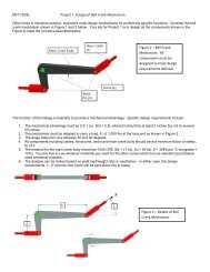
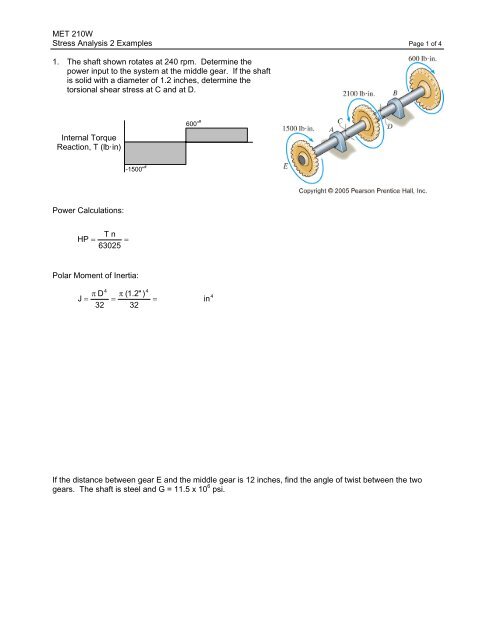
1. The shaft shown rotates at 240 rpm. Determine the<br />
power input to the system at the middle gear. If the shaft<br />
is solid with a diameter of 1.2 inches, determine the<br />
torsional shear stress at C and at D.<br />
Internal Torque<br />
Reaction, T (lb·in)<br />
-1500” # 600” #<br />
Power Calculations:<br />
HP<br />
T n<br />
= 63025<br />
=<br />
Polar Moment of Inertia:<br />
4<br />
4<br />
π D π (1.2" )<br />
J = = =<br />
32 32<br />
in<br />
4<br />
Shear <strong>Stress</strong> at C:<br />
Shear <strong>Stress</strong> at D:<br />
If the distance between gear E and the middle gear is 12 inches, find the angle of twist between the two<br />
gears. The shaft is steel and G = 11.5 x 10 6 psi.
MET 210W<br />
<strong>Stress</strong> <strong>Analysis</strong> 2 <strong>Example</strong>s Page 2 of 4<br />
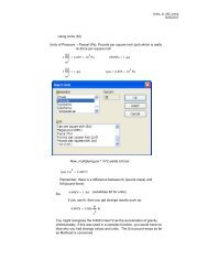
2. The triangular shaft has a 1500 inch-pound torque applied<br />
as shown. Determine the maximum shear stress in the<br />
shaft and the angle of twist of the free end with respect to<br />
the fixed end.<br />
Section Properties:<br />
a = 1.5”<br />
From Mott, Figure 3-10, Page 99:<br />
Q = .050a 3 and K = .0217a 4
MET 210W<br />
<strong>Stress</strong> <strong>Analysis</strong> 2 <strong>Example</strong>s Page 3 of 4<br />
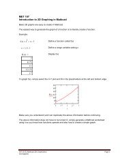
3. The elliptical aluminum tube is subjected to the torque<br />
shown. Dimension b is 1 inch and the wall thickness<br />
is .10 inches. Find the angle of twist in a 48 inch<br />
length of the tube.
MET 210W<br />
<strong>Stress</strong> <strong>Analysis</strong> 2 <strong>Example</strong>s Page 4 of 4<br />
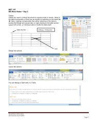
4. Determine the stresses acting at points A and B shown. Show the<br />
stresses on stress elements.<br />
Section Properties from Statics:<br />
X<br />
I x = 7486226 mm 4<br />
y = 99.08 mm<br />
Reactions at Cut:<br />
M CUT<br />
800 mm<br />
F CUT<br />
V CUT<br />
3.6 kN<br />
FBD at Cut<br />
4.8 kN