Aurora-Bearing-610Ca..
Aurora-Bearing-610Ca..
Aurora-Bearing-610Ca..

You also want an ePaper? Increase the reach of your titles
YUMPU automatically turns print PDFs into web optimized ePapers that Google loves.
www.aurorabearing.com • fax 630-859-0971<br />
ultimate radial StatiC<br />
load CaPaCity rod endS<br />
The ultimate radial static load capacity is based upon<br />
the minimum mechanical properties of the design<br />
configuration in the stressed area. The ultimate radial<br />
static load capacity called out in the rod end<br />
specification charts is defined as a single cycle,<br />
unidirectional applied load to cause ultimate failure.<br />
Operating loads should be based on the static load<br />
ratings, incorporating appropriate safety factors to suit<br />
the application. When a rod end is to be applied in full<br />
rotation, the surface speed of the ball should be kept<br />
below 20 feet per minute or the rotational speed should<br />
be below 100 RPM, whichever is lower, with the<br />
operating loads not to exceed 10% of the ultimate<br />
radial static load.<br />
Load ratings listed in the standard detail pages are<br />
applicable to rod ends supplied without grease fittings.<br />
Load ratings for units employing fittings may be affected<br />
due to lighter cross section in the stressed area.<br />
for information on the rod end radial static load<br />
ratings with fittings and other specific load rating<br />
information, consult the aurora <strong>Bearing</strong><br />
engineering department.<br />
aXial StatiC<br />
load CaPaCity rod endS<br />
Axial static load capacity is the force that is applied<br />
through the bore of the ball. For <strong>Aurora</strong> two-piece rod<br />
ends, maximum axial static load capacity is<br />
recommended to be 15 percent of the ultimate radial<br />
static load capacity. For three-piece rod ends,<br />
maximum axial static load capacity is generally<br />
recommended as 10 percent of ultimate radial static<br />
load capacity. It should be noted, however, that on<br />
three-piece units factors such as race material, body<br />
material and dimensions may affect axial static load<br />
capacity. For further information, consult the <strong>Aurora</strong><br />
<strong>Bearing</strong> engineering department.<br />
radial StatiC limit load<br />
CaPaCity SPHeriCal BearinGS<br />
Radial static limit loads are maximum static based on<br />
the maximum permanent set in the bearing race of<br />
0.2% of the ball diameter. If greater permanent set can<br />
be allowed or if alternate race materials are used<br />
consult our engineering department for change factors.<br />
Operating loads are based on the radial static limit load<br />
rating and appropriate safety factors should be utilized<br />
to suit the application.<br />
Max axial load is recommended at 20 percent of the<br />
radial static load. Extreme care should be used on<br />
selecting a sufficiently strong housing to accept this<br />
type of bearing.<br />
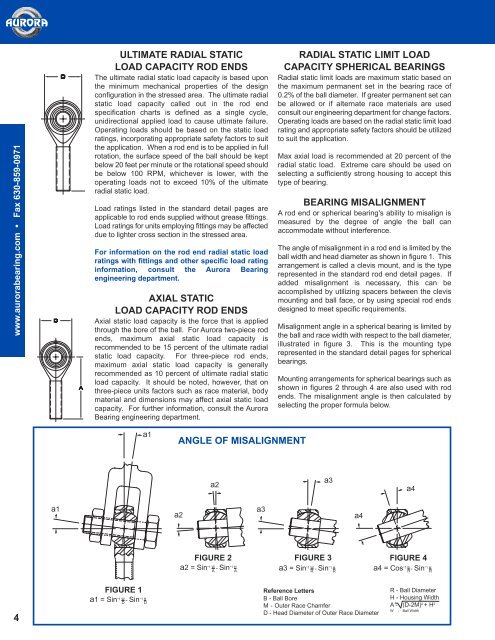
BearinG miSaliGnment<br />
A rod end or spherical bearing's ability to misalign is<br />
measured by the degree of angle the ball can<br />
accommodate without interference.<br />
The angle of misalignment in a rod end is limited by the<br />
ball width and head diameter as shown in figure 1. This<br />
arrangement is called a clevis mount, and is the type<br />
represented in the standard rod end detail pages. If<br />
added misalignment is necessary, this can be<br />
accomplished by utilizing spacers between the clevis<br />
mounting and ball face, or by using special rod ends<br />
designed to meet specific requirements.<br />
Misalignment angle in a spherical bearing is limited by<br />
the ball and race width with respect to the ball diameter,<br />
illustrated in figure 3. This is the mounting type<br />
represented in the standard detail pages for spherical<br />
bearings.<br />
Mounting arrangements for spherical bearings such as<br />
shown in figures 2 through 4 are also used with rod<br />
ends. The misalignment angle is then calculated by<br />
selecting the proper formula below.<br />
a1<br />
anGle of miSaliGnment<br />
a2<br />
a3<br />
a4<br />
a1<br />
a2<br />
a3<br />
a4<br />
4<br />
fiGure 2<br />
fiGure 3<br />
fiGure 4<br />
a2 = Sin -1 W - Sin -1 H a3 = Sin -1 W - Sin -1 a4 = Cos -1 B - Sin -1 A A R R H<br />
R H<br />
R<br />
fiGure 1<br />
reference letters<br />
a1 = Sin -1 W - Sin -1 H<br />
D<br />
D<br />
B - Ball Bore<br />
M-Outer Race Chamfer<br />
D - Head Diameter of Outer Race Diameter<br />
R - Ball Diameter<br />
H - Housing Width<br />
A - (D-2M) 2 + H 2<br />
W - Ball Width