ABB i-bus KNX IP Interface IPS/S 2.1
ABB i-bus KNX IP Interface IPS/S 2.1
ABB i-bus KNX IP Interface IPS/S 2.1

Create successful ePaper yourself
Turn your PDF publications into a flip-book with our unique Google optimized e-Paper software.
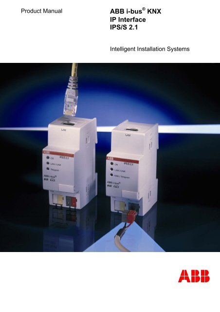
Product Manual <strong>ABB</strong> i-<strong>bus</strong> ® <strong>KNX</strong><br />
<strong>IP</strong> <strong>Interface</strong><br />
<strong>IP</strong>S/S <strong>2.1</strong><br />
Intelligent Installation Systems<br />
<strong>ABB</strong>
This manual describes the function of the <strong>IP</strong> <strong>Interface</strong> <strong>IP</strong>S/S <strong>2.1</strong> with<br />
the application program <strong>IP</strong> <strong>Interface</strong>.<br />
Subject to changes and errors excepted.<br />
Exclusion of liability:<br />
Despite checking that the contents of this document match the hardware and<br />
software, deviations cannot be completely excluded. We therefore cannot accept<br />
any liability for this. Any necessary corrections will be inserted in new versions of<br />
the manual.<br />
Please inform us of any suggested improvements.
<strong>ABB</strong> i-<strong>bus</strong> � <strong>KNX</strong> Contents<br />
Contents<br />
© 2008 <strong>ABB</strong> STOTZ-KONTAKT GmbH i<br />
Page<br />
1 General 3<br />
1.1 Product and functional overview...........................................................3<br />
2 Device technology 5<br />
<strong>2.1</strong> Technical data.......................................................................................5<br />
2.2 Circuit diagram......................................................................................7<br />
2.3 Dimension drawing ...............................................................................8<br />
2.4 Assembly and installation .....................................................................9<br />
2.5 Description of the inputs and outputs .................................................10<br />
2.6 Operating controls ..............................................................................10<br />
2.7 Display elements ................................................................................11<br />
3 Commissioning 13<br />
3.1 Overview.............................................................................................13<br />
3.2 Parameters .........................................................................................13<br />
3.<strong>2.1</strong> Parameter window <strong>IP</strong> settings..........................................................14<br />
3.2.2 Parameter window <strong>IP</strong> address .........................................................15<br />
3.3 Communication objects ......................................................................17<br />
3.4 <strong>IP</strong>S/S as a programming interface......................................................17<br />
3.4.1 Settings from ETS3.0f ......................................................................18<br />
3.4.2 Settings for ETS3.0e ........................................................................20<br />
4 Planning and application 21<br />
4.1 The <strong>IP</strong> <strong>Interface</strong> in the network...........................................................21<br />
4.1.1 <strong>IP</strong> Address of the <strong>IP</strong>S/S ...................................................................21<br />
A Appendix 23<br />
A.1 Ordering information ...........................................................................23<br />
A.2 Notes...................................................................................................24
<strong>ABB</strong> i-<strong>bus</strong> � <strong>KNX</strong> General<br />
1 General<br />
1.1 Product and<br />
functional overview<br />
The <strong>IP</strong> <strong>Interface</strong> <strong>IP</strong>S/S <strong>2.1</strong> connects the <strong>KNX</strong> <strong>bus</strong> with the Ethernet network.<br />
<strong>KNX</strong> telegrams can be sent to or received from other devices via the<br />
network. The device uses the <strong>KNX</strong>net/<strong>IP</strong> protocol from the <strong>KNX</strong> Association<br />
for communication.<br />
In older documents and in the ETS 3.0e the <strong>KNX</strong>net/<strong>IP</strong> protocol is also<br />
referred to as the EIBnet/<strong>IP</strong> protocol.<br />
Both protocols and specifications are identical.<br />
The <strong>IP</strong> <strong>Interface</strong> can program <strong>KNX</strong> devices via the LAN using the ETS 3.0e<br />
(or higher). It can serve as an interface for a visualisation as well. Its <strong>IP</strong><br />
address can be fix, assigned via DHCP or Auto<strong>IP</strong>. For operation an<br />
additional 12 to 30 V DC supply is necessary.<br />
© 2008 <strong>ABB</strong> STOTZ-KONTAKT GmbH 3
<strong>ABB</strong> i-<strong>bus</strong> � <strong>KNX</strong> Device technology<br />
2 Device technology<br />
<strong>IP</strong>S/S <strong>2.1</strong><br />
<strong>2.1</strong> Technical data<br />
2CDC 071 020 F0008<br />
The <strong>IP</strong> <strong>Interface</strong> <strong>2.1</strong> is a modular installation device (MDRC) and forms<br />
the interface between <strong>KNX</strong> installations and <strong>IP</strong> networks. It utilises the local<br />
network (LAN) for fast exchange of telegrams.<br />
<strong>KNX</strong> devices can be programmed via the LAN using ETS 3.0.<br />
The device uses the <strong>KNX</strong>net/<strong>IP</strong> protocol from the <strong>KNX</strong> Association<br />
(Tunnelling).<br />
The <strong>IP</strong> address can be fixed or can be received from a DHCP server.<br />
The power supply range is from 10 to 30 V DC.<br />
Supply Supply voltage Us 10…30 V DC via plug-in terminal<br />
Ripple: < 5 %<br />
Power consumption Maximum 1.9 W at 10 V<br />
Current consumption Maximum 190 mA at 10 V<br />
Leakage loss Maximum 1.9 W at 10 V<br />
Rated voltage Un 12 V DC<br />
Rated current In 145 mA at 12 V<br />
Current consumption <strong>KNX</strong> From <strong>KNX</strong> < 10 mA<br />
Connections <strong>KNX</strong> Bus connection terminal<br />
Plug-in terminal for operating voltage Plug-in terminal<br />
LAN RJ45 socket for 10/100BaseT, IEEE 802.3<br />
networks, AutoSensing<br />
Operating and display elements LED red and button For assignment of the physical address<br />
LED green Operating mode display<br />
LED yellow Network connection indicator<br />
<strong>KNX</strong> telegram traffic indicator<br />
Enclosure <strong>IP</strong> 20 to DIN EN 60529<br />
Safety class II to DIN EN 61140<br />
Isolation category Overvoltage category<br />
Pollution degree<br />
<strong>KNX</strong> safety extra low voltage SELV 24 V DC<br />
III to DIN EN 60664-1<br />
2 to DIN EN 60664-1<br />
Temperature range Operation 0 °C…+45 °C<br />
Storage -25 °C…+55 °C<br />
Transport -25 °C…+70 °C<br />
Ambient conditions Maximum air humidity 93 %, no condensation allowed<br />
© 2008 <strong>ABB</strong> STOTZ-KONTAKT GmbH 5
<strong>ABB</strong> i-<strong>bus</strong> � <strong>KNX</strong> Device technology<br />
Design Modular installation device (MDRC) Modular installation device, ProM<br />
Dimensions 90 x 36 x 64 mm (H x W x D)<br />
Mounting width 2 modules at 18 mm<br />
Mounting depth 68 mm<br />
Installation On 35 mm mounting rail to DIN EN 60 715<br />
Mounting position as required<br />
Weight 0.100 kg<br />
Housing, colour Plastic housing, grey<br />
Approvals <strong>KNX</strong> to EN 50 090-1, -2<br />
CE mark in accordance with the EMC guideline and<br />
low voltage guideline<br />
Application program Maximum number of<br />
communication objects<br />
Maximum number of group<br />
addresses<br />
<strong>IP</strong> <strong>Interface</strong> 0 0 0<br />
Note<br />
Maximum number of<br />
associations<br />
The programming requires EIB Software Tool ETS3 V3.0e or higher.<br />
If ETS3 is used a *.VD3 or higher type file must be imported.<br />
The application program is available in the ETS3 at <strong>ABB</strong>/System<br />
devices/<strong>Interface</strong>s.<br />
The device does not support the closing function of a project or the <strong>KNX</strong><br />
device in the ETS. If you inhibit access to all devices of the project with<br />
a BCU code (ETS3), it has no effect on this device. Data can still be read<br />
and programmed.<br />
© 2008 <strong>ABB</strong> STOTZ-KONTAKT GmbH 6
<strong>ABB</strong> i-<strong>bus</strong> � <strong>KNX</strong> Device technology<br />
2.2 Circuit diagram<br />
<strong>IP</strong>S/S<br />
<strong>2.1</strong><br />
1 LED ON 6 Programming LED<br />
2 LED LAN/LINK 7 Programming button<br />
3 LED telegram 8 Label carrier<br />
4 Supply voltage connection<br />
5 <strong>KNX</strong> connection<br />
9 LAN connection<br />
© 2008 <strong>ABB</strong> STOTZ-KONTAKT GmbH 7<br />
2CDC 072 233 F0008
<strong>ABB</strong> i-<strong>bus</strong> � <strong>KNX</strong> Device technology<br />
2.3 Dimension drawing<br />
© 2008 <strong>ABB</strong> STOTZ-KONTAKT GmbH 8<br />
2CDC 072 235 F0008
<strong>ABB</strong> i-<strong>bus</strong> � <strong>KNX</strong> Device technology<br />
2.4 Assembly and<br />
installation<br />
Accessibility to the device for the purpose of operation, testing, visual<br />
inspection, maintenance and repair must be provided compliant to<br />
DIN VDE 0100-520.<br />
Commissioning requirements<br />
In order to commission the device, a PC with ETS from ETS3 V3.0e or<br />
higher as well as an interface to the <strong>ABB</strong> i-<strong>bus</strong> ® , e.g. via a <strong>KNX</strong> interface<br />
as well as a supply voltage in the range from 10 to 30 V DC is required.<br />
If the <strong>IP</strong> <strong>Interface</strong> or other <strong>KNX</strong> devices are to be programmed via a network<br />
(LAN), a PC with LAN connection is required.<br />
The installation and commissioning may only be carried out by electrical<br />
specialists. The appropriate norms, guidelines, regulations and<br />
specifications should be observed when planning and setting up electrical<br />
installations.<br />
� Protect the device from damp, dirt and damage during transport,<br />
storage and operation.<br />
� Only operate the device within the specified technical data limits!<br />
� The device should only be operated in an enclosed housing<br />
(distribution board)!<br />
Supplied state<br />
The device is assigned with the physical address 15.15.100 in the factory.<br />
The application program is preloaded in the factory. The <strong>IP</strong> address is set to<br />
automatic <strong>IP</strong> assignment (DHCP/Auto<strong>IP</strong>).<br />
Assignment of the physical address<br />
The assignment of the address of the <strong>ABB</strong> i-<strong>bus</strong> ® <strong>IP</strong> INTERFACE is carried<br />
out via the ETS and the programming button on the device.<br />
The device features a programming button for assignment of the physical<br />
device address. The red programming LED lights up after the button has<br />
been pushed. It switches off as soon as the ETS has assigned the physical<br />
address or the programming button is pressed again.<br />
Cleaning<br />
If devices become dirty, they can be cleaned using a dry cloth. Should a dry<br />
cloth not remove the dirt, the devices can be cleaned using a slightly damp<br />
cloth and soap solution. Corrosive agents or solutions should never be used.<br />
Maintenance<br />
The device is maintenance-free. No repairs should be carried out by<br />
unauthorised personnel if damage occurs, e.g. during transport and/or<br />
storage. The warranty expires if the device is opened.<br />
© 2008 <strong>ABB</strong> STOTZ-KONTAKT GmbH 9
<strong>ABB</strong> i-<strong>bus</strong> � <strong>KNX</strong> Device technology<br />
2.5 Description of the inputs<br />
and outputs<br />
2.6 Operating controls<br />
Supply voltage input 10 to 30 V DC<br />
Only a DC voltage in a range of 10 to 30 V may be connected to the power<br />
supply input. We recommend using an NT/S power supply from our range.<br />
Once the supply voltage has been connected to the system, a start routine<br />
is executed in the device. As soon as it is ready for operation – a maximum<br />
of 40 seconds after connecting the supply voltage – the ON LED on front of<br />
the device lights up.<br />
Caution<br />
The supply voltage must be between 10 to 30 V DC.<br />
Otherwise the device may be damaged!<br />
<strong>KNX</strong> connection<br />
The supplied <strong>bus</strong> connection terminal is used to connect to the <strong>KNX</strong> <strong>bus</strong>.<br />
Note<br />
Programming requires ETS3 from version 3.0e or higher.<br />
LAN connection<br />
The network connection is carried out via an Ethernet RJ 45 interface for<br />
LAN networks. The network interface can be operated with a transmission<br />
speed of 10/100 Mbit/s. Network activity is indicated by the LAN/LINK LED<br />
on the front of the device.<br />
There are no operating controls located on the <strong>IP</strong> <strong>Interface</strong>.<br />
© 2008 <strong>ABB</strong> STOTZ-KONTAKT GmbH 10
<strong>ABB</strong> i-<strong>bus</strong> � <strong>KNX</strong> Device technology<br />
2.7 Display elements<br />
Three indicator LEDs are located on the front of the <strong>IP</strong>S/S:<br />
ON LAN/LINK Telegram<br />
ON<br />
� The LED lights up if the power supply is available and the device is<br />
ready for operation.<br />
� The LED flashes when the device starts-up, a maximum 40 seconds<br />
after the supply voltage is applied.<br />
LAN/LINK<br />
� The LED lights up if the device detects a connection to the network.<br />
� The LED flashes if the device detects activity on the network,<br />
e.g. when data is exchanged.<br />
Telegram<br />
� The LED lights up when a connection to the <strong>KNX</strong> is available.<br />
� The LED flashes if the device detects a telegram on the <strong>KNX</strong>.<br />
© 2008 <strong>ABB</strong> STOTZ-KONTAKT GmbH 11
<strong>ABB</strong> i-<strong>bus</strong> � <strong>KNX</strong> Commissioning<br />
3 Commissioning<br />
3.1 Overview<br />
3.2 Parameters<br />
Parameterisation of the <strong>IP</strong> <strong>Interface</strong> is implemented using the Engineering<br />
Tool Software ETS3 from version 3.0e.<br />
Note<br />
In general, the preloaded settings can be retained. If changes to the<br />
parameterisation are necessary, they must be loaded via the <strong>KNX</strong> <strong>bus</strong><br />
(twisted pair).<br />
Only the physical address of the <strong>IP</strong> <strong>Interface</strong> can be programmed via the<br />
LAN.<br />
This chapter describes the parameters of the <strong>IP</strong> <strong>Interface</strong> using the<br />
parameter window. The parameter window features a dynamic structure so<br />
that further parameters or whole parameter windows may be enabled<br />
depending on the parameterisation and the function of the outputs.<br />
The default values of the parameters are underlined,<br />
e.g.<br />
Option: yes<br />
no<br />
© 2008 <strong>ABB</strong> STOTZ-KONTAKT GmbH 13
<strong>ABB</strong> i-<strong>bus</strong> � <strong>KNX</strong> Commissioning<br />
3.<strong>2.1</strong> Parameter window<br />
<strong>IP</strong> settings<br />
In the parameter window <strong>IP</strong> settings, settings on the <strong>IP</strong> side of the <strong>IP</strong><br />
<strong>Interface</strong> are undertaken.<br />
Device name [max. 30 char.]<br />
Options: <strong>ABB</strong> <strong>IP</strong>-<strong>Interface</strong> <strong>IP</strong>S/S<br />
The device name is used for identification of the device on the LAN. After a<br />
search query, e.g. by the ETS, every <strong>KNX</strong>net/<strong>IP</strong> device reports its name and<br />
can be allocated accordingly. For example, the installation location can be<br />
identified by the names assigned to the devices, e.g. <strong>IP</strong>S/S, HALL, SUB7.<br />
The text may be a maximum of 30 characters in length. This name is also<br />
displayed when this device is determined in the ETS as the communications<br />
interface.<br />
For further information see: <strong>IP</strong>S/S as a<br />
programming interface, page 17<br />
<strong>IP</strong> address assignment<br />
Options: automatically (DHCP, Auto<strong>IP</strong>)<br />
fixed<br />
� automatically: In the standard setting the <strong>IP</strong> <strong>Interface</strong> expects the<br />
assignment of an <strong>IP</strong> address by a DHCP server (dynamic host<br />
configuration protocol). This server responds to a request by assigning<br />
a free <strong>IP</strong> address to the device. If a DHCP server is not available in the<br />
network or it does not respond within 30 seconds, the device starts an<br />
auto <strong>IP</strong> procedure. It assigns itself with an address from the reserved<br />
range for auto <strong>IP</strong> addresses (169.254.xxx.yyy).<br />
� fixed: If no DHCP server is installed on the network or if the <strong>IP</strong> address<br />
should remain static, it can be assigned as fixed.<br />
The parameter window <strong>IP</strong> Address appears.<br />
© 2008 <strong>ABB</strong> STOTZ-KONTAKT GmbH 14
<strong>ABB</strong> i-<strong>bus</strong> � <strong>KNX</strong> Commissioning<br />
3.2.2 Parameter window<br />
<strong>IP</strong> address<br />
The parameter window <strong>IP</strong> address is only visible if in the Parameter window<br />
<strong>IP</strong> settings, page 14, the option fixed has been selected for the <strong>IP</strong> address<br />
assignment parameter.<br />
<strong>IP</strong> address<br />
Options: Byte x 0…255<br />
The <strong>IP</strong> address is the unique address of the <strong>IP</strong> <strong>Interface</strong> in the LAN.<br />
This address should be entered in a byte-by-byte manner, e.g. as follows<br />
for address 19<strong>2.1</strong>68.0.10:<br />
Byte 1: 192<br />
Byte 2: 168<br />
Byte 3: 0<br />
Byte 4: 10<br />
Subnet mask<br />
Options: Byte x 0…255<br />
The Subnet mask defines the network class. The subnet mask must be set<br />
to reflect the number and structure of the subnet. In the simplest case of<br />
a small network the subnet mask 255.255.255.0 should be set as follows:<br />
Byte 1: 255<br />
Byte 2: 255<br />
Byte 3: 255<br />
Byte 4: 0<br />
© 2008 <strong>ABB</strong> STOTZ-KONTAKT GmbH 15
<strong>ABB</strong> i-<strong>bus</strong> � <strong>KNX</strong> Commissioning<br />
Default gateway<br />
Options: Byte x 0…255<br />
The parameter Default gateway defines the connection point, e.g. the<br />
<strong>IP</strong> address of a router between networks through which <strong>IP</strong> telegrams<br />
are transferred. These gateways are only available in larger networks.<br />
For smaller networks the setting 0.0.0.0 can be retained.<br />
© 2008 <strong>ABB</strong> STOTZ-KONTAKT GmbH 16
<strong>ABB</strong> i-<strong>bus</strong> � <strong>KNX</strong> Commissioning<br />
3.3 Communication objects<br />
3.4 <strong>IP</strong>S/S as a<br />
programming interface<br />
The <strong>IP</strong> <strong>Interface</strong> <strong>IP</strong>S/S has no <strong>KNX</strong> communication objects.<br />
The <strong>IP</strong> <strong>Interface</strong> <strong>IP</strong>S/S can be used together with the ETS as a programming<br />
interface.<br />
The following settings can be used:<br />
© 2008 <strong>ABB</strong> STOTZ-KONTAKT GmbH 17
<strong>ABB</strong> i-<strong>bus</strong> � <strong>KNX</strong> Commissioning<br />
3.4.1 Settings from ETS3.0f<br />
The ETS connects for programming purposes to the interface’s physical<br />
address in order to program devices in the line.<br />
For this purpose the ETS must be set as follows via the window<br />
Extras/Options/Communication:<br />
� Click Configure interface, a new window appears.<br />
� Click on New.<br />
� The name should<br />
be overwritten, e.g. <strong>IP</strong> <strong>Interface</strong>.<br />
� Select the <strong>KNX</strong>net/<strong>IP</strong> type.<br />
� The ETS now searches automatically<br />
via the LAN connection for<br />
<strong>KNX</strong>net/<strong>IP</strong> devices in the network and indicates them in the combination<br />
field under <strong>KNX</strong>net/<strong>IP</strong> device.<br />
� Select the device from the combination<br />
field. If it is not shown click on<br />
Rescan.<br />
� After selection<br />
of the device, its data, e.g. MAC or plain text name, are<br />
displayed:<br />
� With the acknowledgement<br />
OK, the setup of the <strong>IP</strong>S/S as a<br />
programming interface is completed.<br />
If the required device is not connected, the connection can be checked by<br />
clicking on the button <strong>KNX</strong>net/<strong>IP</strong> Diagnostic Assistant.<br />
© 2008 <strong>ABB</strong> STOTZ-KONTAKT GmbH 18
<strong>ABB</strong> i-<strong>bus</strong> � <strong>KNX</strong> Commissioning<br />
After completion of the settings, the connection to the <strong>IP</strong>S/S can be tested<br />
by clicking on Test in the new window:<br />
The<br />
physical address of the interface can be set via the Settings button.<br />
The following window appears:<br />
It must be assured that the physical<br />
address of the tunnelling connection<br />
matches<br />
the topology. E.g. if the interface is added to line 1.1, a topologically<br />
correct<br />
address would be 15.15.255.<br />
© 2008 <strong>ABB</strong> STOTZ-KONTAKT GmbH 19
<strong>ABB</strong> i-<strong>bus</strong> � <strong>KNX</strong> Commissioning<br />
3.4.2 Settings for ETS3.0e<br />
The settings for the ETS3.0e are mainly identical to those of the ETS3.0f.<br />
However with ETS3.0e the designation EIBnet/<strong>IP</strong> is used instead of<br />
<strong>KNX</strong>net/<strong>IP</strong>.<br />
© 2008 <strong>ABB</strong> STOTZ-KONTAKT GmbH 20
<strong>ABB</strong> i-<strong>bus</strong> � <strong>KNX</strong> Planning and application<br />
4 Planning and<br />
application<br />
4.1 The <strong>IP</strong> <strong>Interface</strong><br />
in the network<br />
4.1.1 <strong>IP</strong> Address of the <strong>IP</strong>S/S<br />
The <strong>IP</strong> <strong>Interface</strong> is designed for use in 10/100 BaseT networks compliant to<br />
IEEE802.3. The device features an AutoSensing function and sets the baud<br />
rate (10 or 100 MBit) automatically.<br />
The <strong>IP</strong> address of the device can be received from a DHCP server. For this<br />
purpose the automatic assignment setting of the <strong>IP</strong> address in the ETS is<br />
required, see Parameter window<br />
<strong>IP</strong> settings, page 14. If no DHCP server is found with this setting, the device<br />
starts an Auto<strong>IP</strong> procedure and autonomously assigns an <strong>IP</strong> address from<br />
the range 169.254.xxx.yyy.<br />
The <strong>IP</strong> address which the device receives during start-up (via DHCP or<br />
Auto<strong>IP</strong>) is retained until the next restart (switch on/off or reprogramming).<br />
If the <strong>IP</strong> address of the <strong>IP</strong>S/S is to have a fixed assignment, in the ETS a<br />
fixed <strong>IP</strong> address (as well as a subnet mask and standard gateway) are set,<br />
see Parameter window<br />
<strong>IP</strong> settings, page 14.<br />
© 2008 <strong>ABB</strong> STOTZ-KONTAKT GmbH 21
<strong>ABB</strong> i-<strong>bus</strong> � <strong>KNX</strong> Appendix<br />
A Appendix<br />
A.1 Ordering information<br />
Short description Designation Order No. bbn 40 16779<br />
© 2008 <strong>ABB</strong> STOTZ-KONTAKT GmbH 23<br />
EAN<br />
Price<br />
group<br />
Weight 1<br />
pc.<br />
[kg]<br />
<strong>IP</strong>S/S <strong>2.1</strong> <strong>IP</strong> <strong>Interface</strong>, MDRC 2CDG 110 098 R0011 664 84 4 26 0.1 1<br />
Packaging<br />
[pc.]
<strong>ABB</strong> i-<strong>bus</strong> � <strong>KNX</strong> Appendix<br />
A.2 Notes<br />
© 2008 <strong>ABB</strong> STOTZ-KONTAKT GmbH 24
<strong>ABB</strong> The<br />
Your <strong>KNX</strong>-Partner<br />
Your EIB- Partner<br />
www.abb.com/knx<br />
technical details in this publication are subject to change without notice.<br />
Pub. No. 2CDC 502 049 M0202


![The Right Decision [Solutions for Hotels] (.PDF)](https://img.yumpu.com/9654011/1/184x260/the-right-decision-solutions-for-hotels-pdf.jpg?quality=85)