Computational Mechanics Research and Support for Aerodynamics ...
Computational Mechanics Research and Support for Aerodynamics ...
Computational Mechanics Research and Support for Aerodynamics ...
- No tags were found...

You also want an ePaper? Increase the reach of your titles
YUMPU automatically turns print PDFs into web optimized ePapers that Google loves.
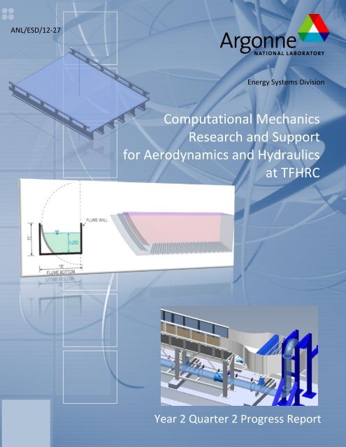
ANL/ESD/12-27<br />
Energy Systems Division<br />
<strong>Computational</strong> <strong>Mechanics</strong><br />
<strong>Research</strong> <strong>and</strong> <strong>Support</strong><br />
<strong>for</strong> <strong>Aerodynamics</strong> <strong>and</strong> Hydraulics<br />
at TFHRC<br />
Year 2 Quarter 2 Progress Report
About Argonne National Laboratory<br />
Argonne is a U.S. Department of Energy laboratory managed by UChicago Argonne, LLC<br />
under contract DE-AC02-06CH11357. The Laboratory’s main facility is outside Chicago,<br />
at 9700 South Cass Avenue, Argonne, Illinois 60439. For in<strong>for</strong>mation about Argonne<br />
<strong>and</strong> its pioneering science <strong>and</strong> technology programs, see www.anl.gov.<br />
Availability of This Report<br />
This report is available, at no cost, at http://www.osti.gov/bridge. It is also available<br />
on paper to the U.S. Department of Energy <strong>and</strong> its contractors, <strong>for</strong> a processing fee, from:<br />
U.S. Department of Energy<br />
Office of Scientific <strong>and</strong> Technical In<strong>for</strong>mation<br />
P.O. Box 62<br />
Oak Ridge, TN 37831-0062<br />
phone (865) 576-8401<br />
fax (865) 576-5728<br />
reports@adonis.osti.gov<br />
Disclaimer<br />
This report was prepared as an account of work sponsored by an agency of the United States Government. Neither the United<br />
States Government nor any agency thereof, nor UChicago Argonne, LLC, nor any of their employees or officers, makes any<br />
warranty, express or implied, or assumes any legal liability or responsibility <strong>for</strong> the accuracy, completeness, or usefulness of any<br />
in<strong>for</strong>mation, apparatus, product, or process disclosed, or represents that its use would not infringe privately owned rights.<br />
Reference herein to any specific commercial product, process, or service by trade name, trademark, manufacturer, or otherwise,<br />
does not necessarily constitute or imply its endorsement, recommendation, or favoring by the United States Government or any<br />
agency thereof. The views <strong>and</strong> opinions of document authors expressed herein do not necessarily state or reflect those of the<br />
United States Government or any agency thereof, Argonne National Laboratory, or UChicago Argonne, LLC.
ANL/ESD/12-27<br />
<strong>Computational</strong> <strong>Mechanics</strong> <strong>Research</strong><br />
<strong>and</strong> <strong>Support</strong> <strong>for</strong> <strong>Aerodynamics</strong> <strong>and</strong> Hydraulics<br />
at TFHRC, Year 2 Quarter 2 Progress Report<br />
by<br />
S.A. Lottes 1 , C. Bojanowski 1 , J. Shen 2 , Z. Xie 2 , <strong>and</strong> Y. Zhai 2<br />
1 Transportation <strong>Research</strong> <strong>and</strong> Analysis Computing Center (TRACC)<br />
Energy Systems Division, Argonne National Laboratory<br />
2 Turner-Fairbank Highway <strong>Research</strong> Center<br />
submitted to<br />
Kornel Kerenyi 1 <strong>and</strong> Harold Bosch 1<br />
1 Turner-Fairbank Highway <strong>Research</strong> Center<br />
June 2012
Table of Contents<br />
1. Introduction <strong>and</strong> Objectives ................................................................................................................. 8<br />
1.1. <strong>Computational</strong> Fluid Dynamics Summary ........................................................................................ 8<br />
2. <strong>Computational</strong> Fluid Dynamics <strong>for</strong> Hydraulic <strong>and</strong> Aerodynamic <strong>Research</strong> ........................................ 10<br />
2.1. Pressure Flow Scour Formula Update <strong>for</strong> Highway Engineering Circular 18 ................................. 10<br />
2.1.1. Testing the Theoretical Model <strong>for</strong> Pressure Flow Scour using CFD analysis, Initial Fit....... 12<br />
2.1.2. Second Fit ............................................................................................................................ 15<br />
2.1.3. Resolving Issues of the Second Fit ...................................................................................... 20<br />
2.1.4. References .......................................................................................................................... 24<br />
2.2. Modeling of the Wind Tunnel Laboratory at TFHRC ...................................................................... 24<br />
2.3. <strong>Computational</strong> Modeling <strong>and</strong> Analysis of Flow through Large Culverts <strong>for</strong> Fish Passage ............. 25<br />
2.3.1. Validation of the CFD models ............................................................................................. 25<br />
2.3.1.1. Comparison of CFD results with experimental data...................................... 26<br />
2.3.1.2. Model accuracy analysis ................................................................................ 49<br />
2.3.1.3. Sources of the error ....................................................................................... 51<br />
2.3.2. References .......................................................................................................................... 51<br />
2.4. Modeling of Truck Generated Salt Spray under Bridge with Sliding Mesh ................................... 52<br />
2.5. New Flume Design <strong>for</strong> Hydraulics Laboratory at TFHRC ................................................................ 52<br />
2.6. Training <strong>and</strong> Technology Transfer ................................................................................................. 58<br />
TRACC/TFHRC Y2Q2 Page 3
List of Figures<br />
Figure 2.1: Bridge deck geometry ............................................................................................................... 11<br />
Figure 2.2: Symmetric section of bridge deck from center of a railing post to halfway to the next post .. 11<br />
Figure 2.3 Vertical contraction <strong>and</strong> definition <strong>for</strong> geometric parameters. ................................................ 13<br />
Figure 2.4 Initial fit based on Equations 2.2 <strong>and</strong> 2.3................................................................................... 14<br />
Figure 2.5 Dividing streamline position <strong>for</strong> different flood heights ........................................................... 17<br />
Figure 2.6 Dividing streamline position <strong>for</strong> different flood heights ........................................................... 18<br />
Figure 2.7 CFD result <strong>for</strong> 3 different velocity levels .................................................................................... 19<br />
Figure 2.8 Equation 2.6 at different velocity levels vs. CFD results ............................................................ 19<br />
Figure 2.9 Equation 2.12 vs. CFD results .................................................................................................... 22<br />
Figure 2.10 Equation 2.13 at different velocity levels (K=0.95) vs. CFD results.......................................... 23<br />
Figure 2.11 Comparison between predicted scour (design scour depth) <strong>and</strong> experimentally measured<br />
scour depth ................................................................................................................................................. 24<br />
Figure 2.12 Sketch of experimental model (left) <strong>and</strong> CAD model of culvert section (right) <strong>for</strong> bed<br />
elevation at 0 inch ....................................................................................................................................... 28<br />
Figure 2.13 Comparison of CFD <strong>and</strong> PIV velocity contour under the condition of 0D bed elevation <strong>and</strong> 1.1<br />
fps <strong>for</strong> 4.5inch water depth (velocity: 33.5 cm/s) ....................................................................................... 29<br />
Figure 2.14 Comparison of CFD <strong>and</strong> PIV velocity contour under the condition of 0D bed elevation <strong>and</strong> 1.1<br />
fps <strong>for</strong> 6 inch water depth (velocity: 33.5 cm/s) ......................................................................................... 30<br />
Figure 2.15 Comparison of CFD <strong>and</strong> PIV velocity contour under the condition of 0D bed elevation <strong>and</strong> 1.1<br />
fps <strong>for</strong> 9 inch water depth (velocity: 33.5 cm/s) ......................................................................................... 31<br />
Figure 2.16 Comparison of CFD <strong>and</strong> PIV velocity contour under the condition of 0D bed elevation <strong>and</strong><br />
0.71 fps <strong>for</strong> 4.5 inch water depth (velocity: 21.6 cm/s) .............................................................................. 32<br />
Figure 2.17 Comparison of CFD <strong>and</strong> PIV velocity contour under the condition of 0D bed elevation <strong>and</strong><br />
0.71 fps <strong>for</strong> 6 inch water depth (velocity:21.6 cm/s) .................................................................................. 33<br />
Figure 2.18 Comparison of CFD <strong>and</strong> PIV velocity contour under the condition of 0D bed elevation <strong>and</strong><br />
0.71 fps <strong>for</strong> 9 inch water depth (velocity: 21.6 cm/s) ................................................................................. 34<br />
TRACC/TFHRC Y2Q2 Page 4
Figure 2.19 Comparison of CFD <strong>and</strong> ADV velocity contour under the condition of 0D bed elevation <strong>and</strong><br />
1.1 fps <strong>for</strong> 9 inch water depth (velocity: 33.5 cm/s) ................................................................................... 35<br />
Figure 2.20 Sketch of experimental model (left) <strong>and</strong> CAD model of culvert section (right) under the<br />
situation of bed elevation at 5.4 inch ......................................................................................................... 36<br />
Figure 2.21 Comparison of CFD <strong>and</strong> PIV velocity contour under the condition of 0.15D bed elevation <strong>and</strong><br />
1.1 fps <strong>for</strong> 4.5 inch water depth (velocity: 33.5 cm/s) ................................................................................ 37<br />
Figure 2.22 Comparison of CFD <strong>and</strong> PIV velocity contour under the condition of 0.15D bed elevation <strong>and</strong><br />
1.1 fps <strong>for</strong> 6 inch water depth (velocity: 33.5 cm/s) ................................................................................... 38<br />
Figure 2.23 Comparison of CFD <strong>and</strong> PIV velocity contour under the condition of 0.15D bed elevation <strong>and</strong><br />
1.1 fps <strong>for</strong> 9 inch water depth (velocity: 33.5 cm/s) ................................................................................... 39<br />
Figure 2.24 Comparison of CFD <strong>and</strong> PIV velocity contour under the condition of 0.15D bed elevation <strong>and</strong><br />
0.71 fps <strong>for</strong> 4.5 inch water depth (velocity: 21.6 cm/s) .............................................................................. 40<br />
Figure 2.25 Comparison of CFD <strong>and</strong> PIV velocity contour under the condition of 0.15D bed elevation <strong>and</strong><br />
0.71 fps <strong>for</strong> 6 inch water depth (velocity: 21.6 cm/s) ................................................................................. 41<br />
Figure 2.26 Comparison of CFD <strong>and</strong> PIV velocity contour under the condition of 0.15D bed elevation <strong>and</strong><br />
0.71 fps <strong>for</strong> 9 inch water depth (velocity: 21.6 cm/s) ................................................................................. 42<br />
Figure 2.27 Sketch of experimental model (left) <strong>and</strong> CAD model of culvert section (right) under the<br />
situation of bed elevation at 10.8 inch ....................................................................................................... 43<br />
Figure 2.28 Comparison of CFD <strong>and</strong> PIV velocity contour under the condition of 0.3D bed elevation <strong>and</strong><br />
1.1 fps <strong>for</strong> 4.5 inch water depth (velocity: 33.5 cm/s) ................................................................................ 44<br />
Figure 2.29 Comparison of CFD <strong>and</strong> PIV velocity contour under the condition of 0.3D bed elevation <strong>and</strong><br />
1.1 fps <strong>for</strong> 6 inch water depth (velocity: 33.5 cm/s) ................................................................................... 45<br />
Figure 2.30 Comparison of CFD <strong>and</strong> PIV velocity contour under the condition of 0.3D bed elevation <strong>and</strong><br />
1.1 fps <strong>for</strong> 9 inch water depth (velocity: 33.5 cm/s) ................................................................................... 46<br />
Figure 2.31 Comparison of CFD <strong>and</strong> PIV velocity contour under the condition of 0.3D bed elevation <strong>and</strong><br />
0.71 fps <strong>for</strong> 4.5 inch water depth (velocity: 21.6 cm/s) .............................................................................. 47<br />
Figure 2.32 Comparison of CFD <strong>and</strong> PIV velocity contour under the condition of 0.3D bed elevation <strong>and</strong><br />
0.71 fps <strong>for</strong> 6 inch water depth (velocity: 21.6 cm/s) ................................................................................. 48<br />
Figure 2.33 Comparison of CFD <strong>and</strong> PIV velocity contour under the condition of 0.3D bed elevation <strong>and</strong><br />
0.71 fps <strong>for</strong> 9 inch water depth (velocity: 21.6 cm/s) ................................................................................. 49<br />
Figure 2.34 A conceptual drawing of the preliminary inlet design ............................................................. 53<br />
TRACC/TFHRC Y2Q2 Page 5
Figure 2.35: Two different transition profiles of trumpet: streamline <strong>and</strong> multi-line................................ 54<br />
Figure 2.36: Comparison of velocity uni<strong>for</strong>mity along different sections .................................................. 55<br />
Figure 2.37: Comparison of velocity uni<strong>for</strong>mity along different sections in the test regime ..................... 56<br />
Figure 2.38: Comparison between with-honeycomb <strong>and</strong> without-honeycomb <strong>for</strong> the streamline trumpet<br />
.................................................................................................................................................................... 57<br />
Figure 2.39: Announcement <strong>for</strong> CFD training course held in March .......................................................... 59<br />
Figure 2.40: Announcement <strong>for</strong> CFD training course held in March, topics <strong>and</strong> tutorials ......................... 60<br />
TRACC/TFHRC Y2Q2 Page 6
List of Tables<br />
Table 2.1: Boundary conditions .................................................................................................................. 26<br />
Table 2.2 Contour plots comparing CFD, PIV, <strong>and</strong> ADV. All figures compare CFD against PIV except Figure<br />
2.19, which compares CFD against ADV. .................................................................................................... 28<br />
Table 2.3 RMSD <strong>and</strong> relative error between CFD <strong>and</strong> experimental results <strong>for</strong> different conditions ....... 50<br />
TRACC/TFHRC Y2Q2 Page 7
1. Introduction <strong>and</strong> Objectives<br />
The computational fluid dynamics (CFD) <strong>and</strong> computational structural mechanics (CSM) focus areas at<br />
Argonne’s Transportation <strong>Research</strong> <strong>and</strong> Analysis Computing Center (TRACC) initiated a project to<br />
support <strong>and</strong> compliment the experimental programs at the Turner-Fairbank Highway <strong>Research</strong> Center<br />
(TFHRC) with high per<strong>for</strong>mance computing based analysis capabilities in August 2010. The project was<br />
established with a new interagency agreement between the Department of Energy <strong>and</strong> the Department<br />
of Transportation to provide collaborative research, development, <strong>and</strong> benchmarking of advanced<br />
three-dimensional computational mechanics analysis methods to the aerodynamics <strong>and</strong> hydraulics<br />
laboratories at TFHRC <strong>for</strong> a period of five years, beginning in October 2010. The analysis methods<br />
employ well benchmarked <strong>and</strong> supported commercial computational mechanics software.<br />
<strong>Computational</strong> mechanics encompasses the areas of <strong>Computational</strong> Fluid Dynamics (CFD),<br />
<strong>Computational</strong> Wind Engineering (CWE), <strong>Computational</strong> Structural <strong>Mechanics</strong> (CSM), <strong>and</strong> <strong>Computational</strong><br />
Multiphysics <strong>Mechanics</strong> (CMM) applied in Fluid-Structure Interaction (FSI) problems.<br />
The major areas of focus of the project are wind <strong>and</strong> water effects on bridges — superstructure, deck,<br />
cables, <strong>and</strong> substructure (including soil), primarily during storms <strong>and</strong> flood events — <strong>and</strong> the risks that<br />
these loads pose to structural failure. For flood events at bridges, another major focus of the work is<br />
assessment of the risk to bridges caused by scour of stream <strong>and</strong> riverbed material away from the<br />
foundations of a bridge. Other areas of current research include modeling of flow through culverts to<br />
improve design allowing <strong>for</strong> fish passage, modeling of the salt spray transport into bridge girders to<br />
address suitability of using weathering steel in bridges, CFD analysis of the operation of the wind tunnel<br />
in the TFHRC wind engineering laboratory.<br />
This quarterly report documents technical progress on the project tasks <strong>for</strong> the period of January<br />
through March 2012.<br />
1.1. <strong>Computational</strong> Fluid Dynamics Summary<br />
The primary <strong>Computational</strong> Fluid Dynamics (CFD) activities during the quarter concentrated on the<br />
development of models <strong>and</strong> methods needed to continue the ongoing work in scour modeling, culvert<br />
modeling, CFD analysis of the Turner-Fairbank wind tunnel, CFD modeling <strong>and</strong> analysis of salt spray from<br />
TRACC/TFHRC Y2Q2 Page 8
large trucks passing under bridges using weathering steel, <strong>and</strong> modeling <strong>and</strong> analysis of concept testing<br />
<strong>for</strong> an in-situ scour device to measure scour related properties of sediment bed material. During this<br />
quarter, modeling <strong>and</strong> analysis of the separation of flow at the leading edge of a flooded bridge deck<br />
was continued to aid in the development of an enhanced approach <strong>for</strong> evaluating scour due to<br />
submergence of bridge decks during floods in the federal guidelines. Modeling of flow through culverts<br />
<strong>for</strong> fish passage continued with the work on a porous media model to capture the effects of large<br />
diameter gravel in the bottom of the culvert revealed some difficulties in obtaining physically realistic<br />
results in the modeling of flow parallel to porous beds. A meshed out rough bed model <strong>for</strong> large<br />
roughness elements was also tested <strong>and</strong> compared against experiment. This model appears to yield<br />
adequate engineering accuracy. Modeling of the wind tunnel in the TFHRC laboratory continued, <strong>and</strong> a<br />
new CFD model was developed to analyze flow in the wind tunnel <strong>and</strong> the room under a variety of flow<br />
conditions including with <strong>and</strong> without furniture. Work on the CFD model using the sliding mesh<br />
capabilities of STAR-CCM+ with multiphase droplet tracking was continued. Simulations <strong>for</strong> a matrix of<br />
conditions are being carried out with different droplet sizes, both a single truck <strong>and</strong> a truck followed by<br />
another truck, <strong>and</strong> two wind speeds with the wind crossing the domain in four directions with respect to<br />
the truck or trucks.<br />
TRACC/TFHRC Y2Q2 Page 9
2. <strong>Computational</strong> Fluid Dynamics <strong>for</strong> Hydraulic <strong>and</strong> Aerodynamic<br />
<strong>Research</strong><br />
During the first quarter of 2012, modeling <strong>and</strong> analysis of the separation of flow at the leading edge of a<br />
flooded bridge deck was continued to aid in the development of an enhanced approach <strong>for</strong> evaluating<br />
scour due to submergence of bridge decks during floods. This work culminated in the completion <strong>and</strong><br />
submission of a new procedure <strong>for</strong> calculating vertical contraction scour in HEC-18 [1] by TFHRC staff in<br />
collaboration with TRACC analysts. Modeling of flow through culverts <strong>for</strong> fish passage continued with<br />
work on using a porous media model to capture the effects of large diameter gravel in the bottom of the<br />
culvert. An alternative approach was also pursued. In this approach a uni<strong>for</strong>m arrangement of large<br />
roughness elements approximately the size of the gravel were meshed out explicitly in the geometry of<br />
the model. Results of CFD simulations with the large roughness elements in the model were compared<br />
against experiment <strong>and</strong> are reported in Section 2.3.1.1. TFHRC provided geometry files <strong>for</strong> their wind<br />
tunnel laboratory <strong>and</strong> the new CFD model was used to analyze flow in the wind tunnel <strong>and</strong> the room<br />
under a variety of flow conditions including with <strong>and</strong> without furniture. The CFD model using the sliding<br />
mesh capabilities of STAR-CCM+ with multiphase droplet tracking is being used to test the effects of a<br />
variety of conditions of droplet distributions under bridges.<br />
2.1. Pressure Flow Scour Formula Update <strong>for</strong> Highway Engineering Circular 18<br />
An update to the submerged-flow bridge scour evaluation procedure in HEC-18 [1] was completed by<br />
TFHRC <strong>and</strong> TRACC. The approach to scour hole depth estimation assumes that the scour process will<br />
enlarge the area under the bridge until it is large enough to pass the flow with a condition of critical<br />
shear stress at the bed. The bridge deck is a bluff body in the flow <strong>and</strong> flow separation will normally<br />
occur at the upstream bottom edge of the submerged bridge deck. The separation zone under the<br />
bridge restricts the area open to flow under the deck <strong>and</strong> is there<strong>for</strong>e an important parameter in reliably<br />
predicting the depth of the scour hole. CFD simulations were per<strong>for</strong>med to investigate the relation<br />
between the initial opening height under the submerged deck be<strong>for</strong>e scour <strong>and</strong> the thickness of the<br />
separation zone, <strong>and</strong> one test was done to see if the thickness of the separation zone changed during<br />
the scour process.<br />
TRACC/TFHRC Y2Q2 Page 10
Flow<br />
direction<br />
Figure 2.1: Bridge deck geometry<br />
The bridge deck with superstructure geometry is shown in Figure 2.1. To reduce computer time <strong>and</strong><br />
eliminate the effects of the flume side walls, the simulations were per<strong>for</strong>med using a section of the<br />
bridge deck cut through the middle of a post <strong>and</strong> running half the distance to the center of the next<br />
post. This geometry is shown in Figure 2.2.<br />
b = 0.058 m<br />
w = 0.26 m<br />
Flow<br />
direction<br />
Figure 2.2: Symmetric section of bridge deck from center of a railing post to halfway to the next post<br />
Symmetric boundary conditions were used on the stream wise sides of the domain. The simulations<br />
were done as single phase flow with a flat water surface using a symmetry boundary condition at the<br />
surface. Previous tests have been done using the multiphase VOF model <strong>for</strong> free surface flow, <strong>and</strong> the<br />
TRACC/TFHRC Y2Q2 Page 11
flat surface assumption is good except in the case with the bridge deck very close to the surface but still<br />
overtopped. The inlet boundary was taken to be a uni<strong>for</strong>m velocity located just at the outlet of the<br />
honeycomb in the TFHRC scour flume. The honeycomb is a flow straightener that also strips off<br />
boundary layers, <strong>and</strong> there<strong>for</strong>e the uni<strong>for</strong>m inlet velocity is a reasonably good assumption applied at<br />
this position.<br />
2.1.1. Testing the Theoretical Model <strong>for</strong> Pressure Flow Scour using CFD analysis, Initial Fit<br />
Testing of the theoretical model was conducted using data from Arneson [2], Umbrell [4], <strong>and</strong> TFHRC [3]<br />
<strong>and</strong> flow visualization using PIV <strong>and</strong> CFD modeling. The bulk of the material presented in this section<br />
pertains to the results of the CFD modeling <strong>and</strong> final tuning of the <strong>for</strong>mula <strong>for</strong> separation zone thickness,<br />
t, used in calculation of scour depth, defined as:<br />
6 7<br />
Vue<br />
h<br />
<br />
ue<br />
y<br />
2<br />
hb<br />
y<br />
s<br />
<br />
t<br />
1 3<br />
KU<br />
D<br />
<br />
<br />
50 <br />
2.1<br />
Where:<br />
y s –<br />
V ue –<br />
h ue –<br />
K U –<br />
D 50 –<br />
t –<br />
is the contracted section between the bottom of the separation zone <strong>and</strong> the lowest point of<br />
the scour hole. This is the depth effective <strong>for</strong> the flow through the bridge opening after scour.<br />
is the average upstream velocity within the area from which all streamlines go under the bridge<br />
deck.<br />
is the depth below the stagnation point upstream, below which all streamlines go under the<br />
bridge superstructure. For a fully inundated bridge, this depth is conservatively taken to be<br />
h ue =h b +T. For partially submerged bridge, h ue =h u =h b +a, where a is the amount of submergence.<br />
is 6.19 <strong>for</strong> SI units, or 11.17 <strong>for</strong> U.S. customary units.<br />
is sediment size (m or ft).<br />
is the thickness of the separation zone at the location above maximum scour.<br />
In Equation 2.1 the value of the separation zone thickness, t, is not available from experimental<br />
measurements. For practical design, it is necessary that t does not become one of the design parameters<br />
to be obtained. It was there<strong>for</strong>e necessary to develop an analytical model that ties t to other measured<br />
parameters <strong>and</strong> then use the experimental data to calibrate this model. This calibrated model, along<br />
with the fitting parameters computed in the calibration process, is used in the final scour evaluation.<br />
TRACC/TFHRC Y2Q2 Page 12
Figure 2.3 Vertical contraction <strong>and</strong> definition <strong>for</strong> geometric parameters.<br />
In the approach taken by TFHRC, a dimensional analysis was used to obtain a <strong>for</strong>mat of the equation <strong>for</strong><br />
the thickness of the separation zone. Experimental data was then used to find the best parameter fit<br />
using the least-squares method. A safety margin was also intentionally added to this <strong>for</strong>mula to allow<br />
sufficient reliability in design. The initial calibration process yielded the following two curves defining<br />
separation zone thickness <strong>for</strong> the cases after <strong>and</strong> be<strong>for</strong>e the deck’s overtopping:<br />
t<br />
h<br />
Where:<br />
g acceleration due to gravity<br />
density of water<br />
viscosity of water<br />
a h u - h b<br />
t<br />
<br />
1.<br />
7<br />
<br />
t<br />
a<br />
<br />
1.<br />
7<br />
<br />
V<br />
gh<br />
t<br />
1.<br />
1T<br />
<br />
<br />
h<br />
t <br />
V <br />
<br />
ga<br />
<br />
0.<br />
3<br />
0.<br />
3<br />
0.<br />
15<br />
1.<br />
2<br />
1<br />
Vh<br />
<br />
t<br />
h<br />
<br />
b h<br />
<br />
<br />
<br />
t<br />
<br />
2.2<br />
hu<br />
hu<br />
<br />
0.<br />
15<br />
1.<br />
2<br />
1<br />
Va<br />
hb<br />
a <br />
<br />
<br />
<br />
<br />
<br />
2.3<br />
hu<br />
hu<br />
<br />
The geometrical parameters used in these equations are defined in Figure 2.3. It is important to note<br />
that the thickness of separation zone from Equations 2.2 <strong>and</strong> 2.3 is not the theoretical separation zone<br />
thickness defined by the boundary streamline. It is obtained from experimental data <strong>and</strong> produces the<br />
best scour depth prediction when used with Equation 2.1. It includes compensation <strong>for</strong> errors/biases of<br />
a number of other factors as well as needed conservatism <strong>for</strong> design. To visualize these curves the<br />
TRACC/TFHRC Y2Q2 Page 13
conditions from Example 1 defined in the new HEC-18 update was adopted here with the following<br />
given parameters:<br />
Upstream channel width <strong>and</strong> bridge opening width (W)= 40 ft (12.2 m)<br />
Total discharge (Q) = 2800 ft 3 /s (79.3 m 3 /s)<br />
Upstream channel discharge (Q 1 ) = 2000 ft 3 /s (56.6 m 3 /s)<br />
Upstream floodplain discharge = 800 ft 3 /s (22.7 m 3 /s)<br />
Upstream channel flow depth (h u )= 10.0 ft (3.0 m)<br />
Bridge opening height (h b ) = 8.0 ft (2.4 m)<br />
Deck thickness (T) = 3 ft (0.91 m)<br />
Bed material D 50 = 15 mm (V c = 6.0 ft/s, 1.8 m/s, V c is the critical velocity <strong>for</strong> the sediment size)<br />
Upstream channel velocity (V=Q 1 /(W hu )) = 2000/(40 x 10) = 5.0 ft/s (1.5 m/s)<br />
Figure 2.4 presents Equations 2.2 <strong>and</strong> 2.3 <strong>for</strong> several different upstream velocities <strong>and</strong> other quantities<br />
defined as above. It was noted that the initial fit allows <strong>for</strong> separation zone thickness significantly<br />
greater than zero <strong>for</strong> the cases where the water level was just slightly above the bottom line of the<br />
bridge superstructure (<br />
. Although Equations 2.2 <strong>and</strong> 2.3 fit to the experimental scour<br />
data well, creation of a significant separation zone when the water is at a level that just touches the<br />
superstructure is counterintuitive. Also there was a discontinuity introduced between the two regions<br />
described by the curves – be<strong>for</strong>e overtopping <strong>and</strong> after overtopping.<br />
Figure 2.4 Initial fit based on Equations 2.2 <strong>and</strong> 2.3<br />
TRACC/TFHRC Y2Q2 Page 14
2.1.2. Second Fit<br />
In order to address these issues a new fit was proposed that would also meet the reliability criteria <strong>for</strong><br />
the experimental data prediction as follows<br />
t<br />
h<br />
b<br />
<br />
1.<br />
7<br />
<br />
<br />
V<br />
gh<br />
u<br />
T<br />
h<br />
t<br />
<br />
<br />
<br />
<br />
0.<br />
3<br />
0.<br />
3<br />
<br />
<br />
<br />
0.<br />
15 0.<br />
2 0.<br />
2<br />
Vhu<br />
hb<br />
ht<br />
<br />
2.4<br />
<br />
<br />
<br />
<br />
h<br />
u<br />
<br />
<br />
<br />
h<br />
u<br />
<br />
<br />
0.<br />
15 0.<br />
2 0.<br />
2<br />
Vhu<br />
h <br />
b a <br />
2.5<br />
t V <br />
1.<br />
7<br />
<br />
h<br />
b gh<br />
u<br />
h<br />
u h<br />
u <br />
This set of equations was obtained in the following way, based on Eq.2.2 <strong>and</strong> Eq. 2.3. h t in the square<br />
root of the first term <strong>and</strong> the second term are of equal <strong>and</strong> opposite sign <strong>and</strong> can there<strong>for</strong>e be replaced<br />
by another parameter without changing the value of the right h<strong>and</strong> side. Choosing the upstream depth,<br />
h u , yields the upstream Froude number as the first factor in the first term <strong>and</strong> the upstream Reynolds<br />
number as the second term. These non-dimensional groups appear to be a more natural choice. The<br />
same replacement can be done <strong>for</strong> “a” in Eq. 2.3. The factor of 1.1 in Eq. 2.2 arose from the<br />
conservative determination of the upstream position of the stagnation streamline in simulation cases<br />
when a railing was present that is not shown in Figure 2.3. The term with 1.1 factor has a negative<br />
exponent, <strong>and</strong> there<strong>for</strong>e dropping the 1.1 factor in the term makes it more conservative, physically<br />
realistic <strong>and</strong> removes the discontinuity in t when the water level is at the overtopping point, h t = T. The<br />
exponent of the last term in Eq. 2.2 <strong>and</strong> Eqn. 2.3 was rounded down to -1 when it could have been<br />
rounded up to -0.8 without substantially affecting the quality of the fit. Rounding it up to -0.8 <strong>and</strong><br />
multiplying the equations through by h t /h b to normalize by the bridge opening height, h b , <strong>and</strong> simplifying<br />
yields Eqs. 2.4 <strong>and</strong> 2.5. This <strong>for</strong>m of the equations addresses both issues noted <strong>for</strong> the initial data fit.<br />
Due to the fact that the discontinuity was removed <strong>and</strong> noting that h t = h u - h b <strong>and</strong> that a = h u - h b the<br />
two equations could be now combined into one equation:<br />
t<br />
h<br />
b<br />
<br />
1.<br />
7<br />
<br />
V<br />
gh<br />
u<br />
<br />
<br />
<br />
0.<br />
3<br />
0.<br />
15<br />
0.<br />
2<br />
0.<br />
2<br />
0.<br />
3<br />
Vhu<br />
h <br />
b h <br />
t h <br />
w<br />
1<br />
<br />
h<br />
u h<br />
<br />
2.6<br />
u h<br />
t <br />
where h w is defined as a wier flow height defined as h w = h t – T <strong>for</strong> h t > T, <strong>and</strong> h w = 0 otherwise.<br />
Subsequently a series of parametric studies <strong>and</strong> CFD simulations were conducted to scrutinize the latest<br />
fit to the experimental data. One part of the parametric study uses the bridge site specified in Example 4<br />
of the updated section of HEC-18 – clear water condition. Multiple cases with different water level (main<br />
variable), different upstream water velocities (secondary variable) <strong>and</strong> different clearance between the<br />
river bed <strong>and</strong> the bridge superstructure were analyzed.<br />
Separation zone streamline plots <strong>for</strong> different water levels in the case with h b =2.4 m are shown in Figure<br />
2.5 <strong>and</strong> Figure 2.6. The plotted cases are <strong>for</strong> an approach velocity of 1.5 m/s, however, further<br />
simulations <strong>for</strong> other velocities showed that the results are nearly independent of velocity (as is<br />
apparent in Figure 2.7). The cases are also <strong>for</strong> the pre-scoured flat bed, <strong>and</strong> consequently the thickest<br />
point of the separation zone is close to the upstream opening of the flooded bridge. Consequently, the<br />
TRACC/TFHRC Y2Q2 Page 15
scour rate is initially highest near the bridge opening but as the scour hole develops, the deepest point<br />
moves close to the downstream end of the bridge opening, <strong>and</strong> the thickest point in the separation zone<br />
also moves back near downstream exit of the opening. This behavior is not covered in CFD results<br />
presented here. For comparison the second fit based on Equation 2.6 is plotted against this data in<br />
Figure 2.8. The dip in t in the CFD results occurs when the water level of the overhang of the bridge<br />
deck surface beyond the first beam, a geometry feature that may be present on most but not all real<br />
bridges, <strong>and</strong> geometry of real bridge superstructures may be more complex than that used in the<br />
analysis <strong>and</strong> result in additional non-monotonic variations of the value of t as a function of h t .<br />
TRACC/TFHRC Y2Q2 Page 16
Figure 2.5 Dividing streamline position <strong>for</strong> different flood heights<br />
TRACC/TFHRC Y2Q2 Page 17
Figure 2.6 Dividing streamline position <strong>for</strong> different flood heights<br />
TRACC/TFHRC Y2Q2 Page 18
Figure 2.7 CFD result <strong>for</strong> 3 different velocity levels<br />
Figure 2.8 Equation 2.6 at different velocity levels vs. CFD results<br />
TRACC/TFHRC Y2Q2 Page 19
2.1.3. Resolving Issues of the Second Fit<br />
Attention was given to three areas of the results in which the previous fit showed potential issues. These<br />
areas were:<br />
1. When the submergence just starts— the amount of submergence, h t , is small. It is expected that<br />
the separation zone thickness would approach zero when h t approaches zero. The relationship<br />
between t <strong>and</strong> h t are shown by CFD result to be nearly linear up to the point the deck overhang<br />
starts to be inundated.<br />
2. When a significant weir flow occurs—the amount of submergence, h t , is large. It is observed in<br />
previous physical <strong>and</strong> CFD simulations that t decreases with h t when the superstructure is fully<br />
inundated. While recent CFD simulations find t remaining nearly constant after full inundation<br />
starts, the simulations were based on an unscoured stream bed. It is expected that if scour hole<br />
develops, t would increase because of the greater size of the bridge opening <strong>and</strong> would also<br />
show some increasing trend with h t . However, the t given by the proposed equation is not<br />
bounded <strong>for</strong> large h t . It approaches infinity when h t approaches infinity.<br />
3. When water velocity is higher—<strong>for</strong> example, when velocity is 2.5 m/s, the predicted value of t<br />
from the fitted equation falls well below the CFD prediction. The proposed equation has a<br />
strong inverse dependence on velocity, with a total power of -0.45. Since the Reynolds number<br />
of the orifice flow is fairly high even <strong>for</strong> relatively minor flooding <strong>and</strong> the bridge cross section<br />
consists of sharp edges, it is expected that the velocity dependence is very low. CFD simulations<br />
also show minimal changes in t <strong>for</strong> different upstream velocities.<br />
The proposed equations of the second fit give zero t when h t is near zero, <strong>and</strong> are somewhat<br />
conservative <strong>for</strong> small h t . Problem Area 1 is there<strong>for</strong>e less of a concern <strong>for</strong> the second fit.<br />
The increase of t with significant weir flow is associated with the last term of the fit Equation:<br />
TRACC/TFHRC Y2Q2 Page 20<br />
0.<br />
3<br />
h <br />
w<br />
1<br />
<br />
h<br />
<br />
2.7<br />
t <br />
This term is a result of the Froude number term of the fully inundated scour equation <strong>and</strong> is never datafitted<br />
individually. It is there<strong>for</strong>e reasonable to make changes to it if there is a good basis. By<br />
observation from CFD <strong>and</strong> engineering judgment, it is likely that the increasing trend of t with h t is not as<br />
strong as that shown in Figure 2.8. A smaller exponent appears warranted to reduce the concern of<br />
Problem Area 2.<br />
Problem Area 3 needs to be discussed from two different aspects:<br />
1. Format of equation: The Froude number, F r , <strong>and</strong> Reynolds number, R e , terms both contain<br />
factors V <strong>and</strong> h u . When the exponent of F r is twice as that of R e , h u is eliminated. Whereas the<br />
velocity terms in F r <strong>and</strong> Re are multiplied <strong>and</strong> their influence increases. If the exponent of F r <strong>and</strong><br />
R e are the same in magnitude <strong>and</strong> have opposite sign, then the velocity terms in them are<br />
eliminated, while the h u terms become more pronounced. The implication of V terms having a<br />
large exponent is a strong inverse velocity dependence. The result of h u terms having a large
exponent is that t does not scale with bridge dimensions <strong>and</strong> flow depths. Both possibilities are<br />
against CFD findings <strong>and</strong> engineering experience.<br />
2. Experimental procedure: The fit equations have parameters that are fitted to experimental data.<br />
Values of the exponents have produced a very good fitting to lab data. If the current exponents<br />
indicate a dependence on velocity, it is likely that there will be some dependence within the<br />
range of the sets of experiments, however, the dependence may be small.<br />
Three potential approaches were proposed in discussions between TFHRC <strong>and</strong> TRACC to address these<br />
issues:<br />
Approach (1): Maintain scaling without distortion. The current equations provide t that scales with<br />
linear dimensions <strong>and</strong> fits data well. The weak point of this fit is that it has strong dependency on the<br />
velocity <strong>and</strong> t decreases significantly when at higher velocity. It is believed that the source of velocity<br />
dependence is a result of the data analysis scheme that leads to the result. t is calculated by subtracting<br />
the effective orifice flow depth, y 2 , from the total depth, h b +y s . y 2 is obtained from discharge, V ue h ue or<br />
Q, <strong>and</strong> critical velocity, V c . The equation <strong>for</strong> critical velocity is based on uni<strong>for</strong>m, fully developed flow in<br />
an open channel. y 2 from this method may contain a certain amount of error that is related to velocity.<br />
This error may be compensated in the fitted equations that lead to t. However, engineering judgment<br />
supports the proposition that the resultant scour depth, y s , should be free of unrealistic influence from<br />
velocity, <strong>and</strong> leaving the dependence in the fitted equation, could under some real case full scale<br />
conditions lead to under prediction of scour depth.<br />
Approach (2): Remove the velocity dependence. With a significant velocity dependence, current design<br />
equations are not consistent with CFD results over the fairly narrow range of velocities tested (which is<br />
nearly completely independent from velocity), but the fitted equation is very close to the CFD results at<br />
one specific velocity. This velocity can be used as a reference that anchors the design equation to the<br />
CFD-predicted values. If V = 0.5 m/s is chosen, the Froude number <strong>and</strong> Reynolds number terms are:<br />
0.<br />
3<br />
0.<br />
15<br />
V Vh 0.<br />
5 <br />
<br />
u<br />
<br />
0.<br />
5 <br />
<br />
<br />
1<br />
<br />
2.8<br />
gh<br />
u<br />
g<br />
4.<br />
13<br />
Note that the h u factor vanishes because -0.3 is twice -0.15. The equations <strong>for</strong> t become:<br />
0.<br />
3<br />
0.<br />
15<br />
Or in a single equation <strong>for</strong>m<br />
t<br />
h<br />
b<br />
0.<br />
2<br />
0.<br />
2<br />
0.<br />
1<br />
1.<br />
7 h <br />
b h <br />
t T <br />
<br />
4.<br />
13<br />
<br />
h<br />
<br />
<br />
u h<br />
<br />
<br />
u h<br />
<br />
2.9<br />
t <br />
t<br />
h<br />
b<br />
0.<br />
2<br />
0.<br />
2<br />
1.<br />
7 h <br />
b a <br />
<br />
4.<br />
13<br />
<br />
h<br />
<br />
<br />
u h<br />
<br />
2.10<br />
u <br />
t<br />
h<br />
b<br />
0.<br />
2<br />
0.<br />
2<br />
0.<br />
1<br />
1.<br />
7 h <br />
b h <br />
t h <br />
w<br />
1<br />
4.<br />
13<br />
<br />
h<br />
<br />
<br />
u h<br />
<br />
<br />
u h<br />
<br />
2.11<br />
t <br />
These equations maintain consistency with CFD results (flat bed). To increase the level of resemblance<br />
with CFD results <strong>and</strong> engineering experience, the exponent of T/h t or 1-h w /h t is changed to -0.1 to<br />
TRACC/TFHRC Y2Q2 Page 21
educe the rate of increase <strong>for</strong> y when h t gets larger. In order to increase reliability of the design the<br />
scaling factor was subsequently modified from 1.7/4.13 to 0.5 yielding:<br />
t<br />
h<br />
b<br />
0.<br />
2<br />
0.<br />
2<br />
0.<br />
1<br />
hb<br />
ht<br />
hw<br />
<br />
0.<br />
5<br />
<br />
1<br />
h<br />
<br />
<br />
u h<br />
<br />
<br />
u h<br />
<br />
2.12<br />
t <br />
This fit has the advantage of a simple <strong>for</strong>m <strong>and</strong> no dependency on the velocity. With the safety factor it<br />
over-predicts the CFD results <strong>for</strong> the whole range of applicable values of h t , as is required to ensure that<br />
scour is not under predicted. The quality of the fit to the experimental data was also good.<br />
Figure 2.9 Equation 2.12 vs. CFD results<br />
Approach (3): Balanced consistency between velocity <strong>and</strong> length scale. A power of -0.45 produces a<br />
considerable effect from velocity, known to be physically unrealistic. To reduce this effect, one can<br />
reduce the exponent of F r <strong>and</strong> R e proportionally (keeping the power of h u zero so there is no scaling<br />
issue). If they are cut in half, the equations become:<br />
t<br />
h<br />
b<br />
<br />
K<br />
<br />
V<br />
gh<br />
u<br />
<br />
<br />
<br />
0 . 15<br />
0.<br />
075 0.<br />
2 0.<br />
2<br />
0.<br />
1<br />
Vh<br />
<br />
u<br />
hb<br />
ht<br />
h<br />
<br />
<br />
<br />
<br />
<br />
1<br />
<br />
w<br />
<br />
2.13<br />
hu<br />
hu<br />
ht<br />
<br />
This expression has much less velocity dependence, but does not fit experimental data very well.<br />
TRACC/TFHRC Y2Q2 Page 22
Figure 2.10 Equation 2.13 at different velocity levels (K=0.95) vs. CFD results<br />
Thorough analysis of the possible solutions led to the conclusion that the best choice is the equation<br />
having no dependence on the upstream velocity. If it comes to the quality of the fits to the experimental<br />
data all the presented choices gave similar fit <strong>and</strong> reliability indicators. Figure 2.11 shows design<br />
equation of approach 2 compared to the experimental data sets. Obtaining good fits of experimental<br />
data sets using any of the design equations in the various approaches could be due to the fact that the<br />
experimental data did not cover the whole possible range of applicable cases <strong>and</strong> were all done at<br />
laboratory scale. The direction of future experiments to further improve the design equation should be<br />
aimed to cover cases outside of the already tested domain. Such tests would likely greatly improve the<br />
reliability of the fitted <strong>for</strong>mula. The equation without the velocity dependence provided the simplest<br />
<strong>for</strong>m, which makes it easy to apply <strong>for</strong> the engineers. Also locking it at one specific level assures that the<br />
unverified inverse dependency on velocity would not lead to unsafe prediction of t <strong>for</strong> some unverified<br />
cases. Equation 2.12 was thus incorporated to the new HEC-18.<br />
Figure 2.11 shows the comparison between scour depths predicted by Equation 2.12 (“Design Scour<br />
Depth”) with the measured scour depth from experiments. The predicted value is safely greater than<br />
observed scour without excessive conservatism.<br />
TRACC/TFHRC Y2Q2 Page 23
Design Scour Depth<br />
0.400<br />
0.350<br />
0.300<br />
Arneson<br />
Umbrell<br />
TFHRC<br />
Line of Agreement<br />
0.250<br />
0.200<br />
0.150<br />
0.100<br />
0.050<br />
0.000<br />
0.000 0.050 0.100 0.150 0.200 0.250 0.300 0.350 0.400<br />
Measured Scour Depth<br />
Figure 2.11 Comparison between predicted scour (design scour depth) <strong>and</strong> experimentally measured scour<br />
depth<br />
2.1.4. References<br />
1. “Evaluating Scour at Bridges,” Hydraulic Engineering Circular No. 18, FHWA-HIF-12-003, April,<br />
2012.<br />
2. Arneson, L. A., <strong>and</strong> Abt, S. R., “Vertical contraction scour at bridges with water flowing under<br />
pressure conditions.” Transportation <strong>Research</strong> Record. 1647, 10-17, 1998.<br />
3. Shan, H., Xie, Z., Bojanowski, C., Suaznabar, O., Shen, J., Lottes, S., <strong>and</strong> Kerenyi, K., “Submerged-<br />
Flow Bridge Scour under Clear-Water Conditions,” FHWA Report, DTFH61-11-D-00010, 2011.<br />
4. Umbrell, E. R., Young, G. K., Stein, S. M., <strong>and</strong> Jones, J. S., “Clear-water contraction scour under<br />
bridges in pressure flow”. J. Hydraul. Engrg. 124(2), 236-240, 1998.<br />
2.2. Modeling of the Wind Tunnel Laboratory at TFHRC<br />
The geometry files provided <strong>for</strong> the initial development of the wind tunnel <strong>and</strong> room model indicated<br />
the pulley on the fan drive shaft was a solid disk. A visit to TFHRC in January, 2012, included a tour of<br />
the wind tunnel laboratory, <strong>and</strong> during that visit, it was noted that the pulley was not a solid disk but<br />
was open with six spokes. The model is currently being modified to have a pulley that matches the 6<br />
spoke wheel of the laboratory, <strong>and</strong> the model is being moved from version 6.04 to 7.02 of STAR-CCM+.<br />
The open, spoked pulley on the side of the wind tunnel with the least resistence <strong>for</strong> return air flow is<br />
expected to increase the asymmetry in the test section in the simulations by a small amount. Results<br />
will be reported in the next quarter report.<br />
TRACC/TFHRC Y2Q2 Page 24
2.3. <strong>Computational</strong> Modeling <strong>and</strong> Analysis of Flow through Large Culverts <strong>for</strong> Fish<br />
Passage<br />
Fish passage through culverts is an important component of road <strong>and</strong> stream crossing design. As water<br />
runoff volume increases, the flow often actively degrades waterways at culverts <strong>and</strong> may interrupt<br />
natural fish migration. Culverts are fixed structures that do not change with changing streams <strong>and</strong> may<br />
instead become barriers to fish movement. The most common physical characteristics that create<br />
barriers to fish passage include excessive water velocity, insufficient water depth, large outlet drop<br />
heights, turbulence within the culvert, <strong>and</strong> accumulation of sediment <strong>and</strong> debris. Major hydraulic<br />
criteria influencing fish passage are: flow rates during fish migration periods, fish species, roughness,<br />
<strong>and</strong> the length <strong>and</strong> slope of the culvert.<br />
The objective of this work is to develop approaches to CFD modeling of culvert flows <strong>and</strong> to use the<br />
models to per<strong>for</strong>m analysis to assess flow regions <strong>for</strong> fish passage under a variety of flow conditions.<br />
The flow conditions to be tested with CFD analysis are defined in the tables of a work plan from TFHRC<br />
[6]. The CFD models are being verified by comparing computational results with data from experiments<br />
conducted at TFHRC. A primary goal of CFD analysis of culverts <strong>for</strong> fish passage is to determine the local<br />
cross section velocities <strong>and</strong> flow distributions in corrugated culverts under varying flow conditions. In<br />
order to evaluate the ability of fish to traverse corrugated culverts, the local average velocity in vertical<br />
strips from the region adjacent to the culvert wall out to the centerline under low flow conditions will be<br />
determined.<br />
A primary goal of the CFD analysis during this quarter has been the detailed comparison among the<br />
results from CFD <strong>and</strong> those from Particle Image Velocimetry (PIV) <strong>and</strong> Acoustic Doppler Velocimetry<br />
(ADV). The challenge of this task included the variation of measurable area over the entire cross section<br />
by the three methods, the difference in original data grid <strong>for</strong>mat, <strong>and</strong> finding a simple representation of<br />
the discrepancies in velocity distribution. Most part of the comparisons were done between CFD <strong>and</strong><br />
PIV data. While ADV measurements were limited due to the significant cropping of the flow section, the<br />
ADV was considered a very reliable tool <strong>and</strong> there<strong>for</strong>e was used to cross-check the comparison done<br />
between CFD <strong>and</strong> PIV under deep water conditions. Good agreement was observed among these three<br />
methods.<br />
2.3.1. Validation of the CFD models<br />
Particle Image Velocimetry (PIV) <strong>and</strong> Acoustic Doppler Velocimetry (ADV) were two methods used to<br />
obtain the velocity data from the physical modeling. The data from physical modeling provided reliable<br />
means in calibrating <strong>and</strong> validating the CFD modeling. For each flow condition specified in the test<br />
matrix <strong>for</strong> physical modeling [6], comparisons were made between velocity data from CFD modeling <strong>and</strong><br />
those from physical modeling. The results of the comparison verified adequacy of the CFD modeling <strong>and</strong><br />
helped in fine-tuning the models to better simulate the corrugated metal pipe culvert in low flow<br />
conditions. A large number of CFD modeling beyond the range of the physical modeling is in progress to<br />
TRACC/TFHRC Y2Q2 Page 25
extend the impact of the findings to a greater variety of culvert geometry <strong>and</strong> flow conditions with good<br />
confidence.<br />
2.3.1.1. Comparison of CFD results with experimental data<br />
The hydraulic flume used <strong>for</strong> testing culverts in the fish passage study had a width the same as the<br />
radius of the selected culvert pipe. It was there<strong>for</strong>e possible to fit an entire quarter of the pipe into the<br />
flume widthwise. The quarter-pipe setup allowed optimal visibility to the flow through the translucent<br />
flume wall <strong>for</strong> the access of laser light sheet <strong>and</strong> camera that were required by PIV.<br />
The primary validation ef<strong>for</strong>t consisted of a comparison of model predictions of velocity distribution<br />
from the STAR-CCM+ software against experimental data under various average velocities, flow depths,<br />
<strong>and</strong> gravel bed elevations. Analyses were conducted to quantify discrepancies between CFD output <strong>and</strong><br />
experimentally measured values, <strong>and</strong> to assess how these discrepancies affect the qualification of a<br />
culvert as fish passable.<br />
As mentioned in previous reports, test scenarios per<strong>for</strong>med in the physical modeling included three<br />
different water depths, two velocities, <strong>and</strong> three bed elevations. CFD models <strong>for</strong> the calibration process<br />
were created precisely following the geometry of the physical models. Single-phase models with cyclic<br />
boundary conditions were used. Validation work presented in previous reports showed good agreement<br />
between uni<strong>for</strong>m flow results from this highly efficient approach <strong>and</strong> those from time-consuming fullbarrel<br />
VOF modeling. Table 2.1 shows the types of boundary conditions specified in the CFD modeling:<br />
Table 2.1: Boundary conditions<br />
boundary name type<br />
Face at minimum z (flow<br />
direction) value<br />
Face at maximum z (flow<br />
direction) value<br />
Inlet<br />
Outlet<br />
Velocity inlet<br />
Pressure outlet<br />
Top of the bounding box Top Symmetry plane<br />
Centerline face Center No-slip wall<br />
Select all the other faces Barrel No-slip wall<br />
Special attention was given to the centerline face. In order to obtain better agreement with the physical<br />
model, the centerline face boundary type was set to be a non-slip wall in the quarter culvert models,<br />
which imitated the zero velocity at the sidewall of the flume. However it should be changed to<br />
symmetry plane in the extended simulation <strong>for</strong> full size culvert models because the non-slip wall<br />
conditions would not exist in a real pipe. Symmetry plane indicates a surface where normal velocity <strong>and</strong><br />
normal gradient of in-plane velocity are both zero. The effect of the difference between boundary<br />
conditions used in the quarter culvert model <strong>and</strong> those used in full size culvert model will be identified<br />
when the extended CFD simulations on full-scale pipes are complete.<br />
TRACC/TFHRC Y2Q2 Page 26
Bed elevation is defined as the depth of the culvert that is buried under the gravel bed. The illustration<br />
of the comparison between CFD results <strong>and</strong> experimental data is organized into three sections based on<br />
three different bed elevations of 0 inch, 5.4 inch (0.15D, D is the pipe diameter.) <strong>and</strong> 10.8 inch (0.3D).<br />
For each case, two velocities <strong>and</strong> three flow depths are used. The accuracy of analyses <strong>and</strong> the sources<br />
of error are discussed <strong>for</strong> each section.<br />
The development of the CFD models from the VOF multi-phase model to the truncated single phase<br />
model with cyclic boundary was presented in the previous report. With the premise of the uni<strong>for</strong>m flow,<br />
the VOF multi-phase model can be replaced by the single-phase model. As discussed previously, the<br />
small increase in water velocity from the single phase model was conservative <strong>for</strong> the analysis to<br />
determine if the flow permits fish passage, <strong>and</strong> the general velocity distributions were similar between<br />
the two approaches. Furthermore, the truncated single phase model with cyclic boundary could provide<br />
the same velocity result as single-phase model without tilting <strong>and</strong> flap gate. Given the large amount of<br />
tests in the test matrix, the more efficient truncated single phase model with cyclic boundary was the<br />
ideal choice. Meanwhile, finer mesh could be utilized in the shorter model to improve accuracy of the<br />
CFD model. The discussion in following sections on the validation of CFD modeling are based on the<br />
results from the truncated single phase approach using cyclic boundary conditions.<br />
The STAR-CCM+ models were validated against two independent experimental velocity data sets:<br />
velocities measured by ADV <strong>and</strong> those captured by PIV. There was a significant area near the walls that<br />
the ADV probe cannot reliably measure velocity. Although this made the amount of useful ADV data in<br />
shallow flow conditions very limited, the ADV measurements still served the purpose as a cross check on<br />
the PIV data very well. CFD data results cover the entire flow cross section. Depending upon the relative<br />
depth <strong>and</strong> the bed elevation, the number of mesh cells varied between 58661 <strong>and</strong> 875087. Meanwhile,<br />
more data points were taken near the boundary of the culvert than in the center of the water body in<br />
order to obtain more precise flow field data near the corrugated wall. The results showed that the<br />
velocity vector was mainly in the flow direction (z-direction) with small components of flow in the x-<br />
direction <strong>and</strong> y-direction. The results were plotted in color-coded contour. Figure 2.13 through Figure<br />
2.33 compare the data from CFD, PIV, <strong>and</strong> ADV <strong>for</strong> 3 water depths, 3 sediment elevations, <strong>and</strong> 2<br />
velocities. These contour plots provide visual evidence in the agreement between CFD simulations <strong>and</strong><br />
experiments. All figures compare CFD against PIV except Figure 2.19, which compares CFD against ADV.<br />
Table 2.2 shows the flow conditions <strong>for</strong> each plotting that compares CFD to PIV <strong>and</strong> CFD to ADV. With a<br />
broad b<strong>and</strong> of area near the walls that has no data, the ADV presents sizable contour plot area only<br />
when flow depth is 9 inch. The ADV contour plot is a supplementary tool to cross-verify the accuracy of<br />
the PIV measurements.<br />
TRACC/TFHRC Y2Q2 Page 27
Table 2.2 Contour plots comparing CFD, PIV, <strong>and</strong> ADV. All figures compare CFD against PIV except Figure 2.19,<br />
which compares CFD against ADV.<br />
Velocity 1.1’/s 0.71’/s<br />
Flow Depth 4.5” 6” 9” 4.5” 6” 9”<br />
Sediment<br />
elevation<br />
0 D Figure 2.13 Figure 2.14 Figure 2.15 Figure 2.16 Figure 2.17 Figure 2.18<br />
Figure 2.19<br />
0.15 D Figure 2.21 Figure 2.22 Figure 2.23 Figure 2.24 Figure 2.25 Figure 2.26<br />
0.3 D Figure 2.28 Figure 2.29 Figure 2.30 Figure 2.31 Figure 2.32 Figure 2.33<br />
(1) Bed elevation at 0 inch<br />
Figure 2.12 shows the experimental model (left) <strong>and</strong> the Computer Aided Design (CAD) model of culvert<br />
section geometry <strong>for</strong> the use in truncated single-phase modeling (right). The cross section of the pipe at<br />
the crest of the corrugation is different from that at the trough of the corrugation. The results shown in<br />
Figure 2.13 through Figure 2.18 are taken from a trough section, i.e. the largest cross section.<br />
Figure 2.12 Sketch of experimental model (left) <strong>and</strong> CAD model of culvert section (right) <strong>for</strong> bed elevation at 0<br />
inch<br />
TRACC/TFHRC Y2Q2 Page 28
Figure 2.13 Comparison of CFD <strong>and</strong> PIV velocity contour under the condition of 0D bed elevation <strong>and</strong> 1.1 fps <strong>for</strong><br />
4.5inch water depth (velocity: 33.5 cm/s)<br />
TRACC/TFHRC Y2Q2 Page 29
Figure 2.14 Comparison of CFD <strong>and</strong> PIV velocity contour under the condition of 0D bed elevation <strong>and</strong> 1.1 fps <strong>for</strong><br />
6 inch water depth (velocity: 33.5 cm/s)<br />
TRACC/TFHRC Y2Q2 Page 30
Figure 2.15 Comparison of CFD <strong>and</strong> PIV velocity contour under the condition of 0D bed elevation <strong>and</strong> 1.1 fps <strong>for</strong><br />
9 inch water depth (velocity: 33.5 cm/s)<br />
TRACC/TFHRC Y2Q2 Page 31
Figure 2.16 Comparison of CFD <strong>and</strong> PIV velocity contour under the condition of 0D bed elevation <strong>and</strong> 0.71 fps <strong>for</strong><br />
4.5 inch water depth (velocity: 21.6 cm/s)<br />
TRACC/TFHRC Y2Q2 Page 32
Figure 2.17 Comparison of CFD <strong>and</strong> PIV velocity contour under the condition of 0D bed elevation <strong>and</strong> 0.71 fps <strong>for</strong><br />
6 inch water depth (velocity:21.6 cm/s)<br />
TRACC/TFHRC Y2Q2 Page 33
Figure 2.18 Comparison of CFD <strong>and</strong> PIV velocity contour under the condition of 0D bed elevation <strong>and</strong> 0.71 fps <strong>for</strong><br />
9 inch water depth (velocity: 21.6 cm/s)<br />
TRACC/TFHRC Y2Q2 Page 34
Figure 2.19 Comparison of CFD <strong>and</strong> ADV velocity contour under the condition of 0D bed elevation <strong>and</strong> 1.1 fps <strong>for</strong><br />
9 inch water depth (velocity: 33.5 cm/s)<br />
(2) Bed elevation at 5.4 inch<br />
The variation of bed elevation is an important <strong>and</strong> unique consideration in this study. Ideally, a gravel<br />
bed exhibits two special characteristics: (1) An elevated boundary that changes the geometry of the<br />
channel <strong>and</strong> roughness of the boundary. (2) A permeable material in the gravel-occupied area that<br />
allows relatively low velocity flow <strong>and</strong> significant energy dissipation. In this stage of the study, the effect<br />
of (2) is neglected. Although this does not perfectly simulate the field sediment condition, it is more<br />
TRACC/TFHRC Y2Q2 Page 35
consistent with the lab test setup, <strong>for</strong> which a single layer of gravel is laid onto the solid flume bed to<br />
represent the roughness of the gravel bed. Figure 2.20 shows the sketch of the experimental model<br />
(left) <strong>and</strong> the CAD model of culvert section geometry (right). The dimples shown in the CAD model were<br />
created by a 2-D periodical function that yields a similar roughness as that of natural bed with specified<br />
gravel size.<br />
Figure 2.20 Sketch of experimental model (left) <strong>and</strong> CAD model of culvert section (right) under the situation of<br />
bed elevation at 5.4 inch<br />
The CFD simulations <strong>for</strong> clean culvert pipes described in the previous section were repeated on the<br />
model shown in Figure 2.20. Results were compared in Figure 2.21 through Figure 2.23. Similarly, the<br />
trough cross-section (the largest cross-sectional area) was used <strong>for</strong> the comparison between CFD <strong>and</strong><br />
PIV. Detailed parameters are given in Table 2.2.<br />
TRACC/TFHRC Y2Q2 Page 36
Figure 2.21 Comparison of CFD <strong>and</strong> PIV velocity contour under the condition of 0.15D bed elevation <strong>and</strong> 1.1 fps<br />
<strong>for</strong> 4.5 inch water depth (velocity: 33.5 cm/s)<br />
TRACC/TFHRC Y2Q2 Page 37
Figure 2.22 Comparison of CFD <strong>and</strong> PIV velocity contour under the condition of 0.15D bed elevation <strong>and</strong> 1.1 fps<br />
<strong>for</strong> 6 inch water depth (velocity: 33.5 cm/s)<br />
TRACC/TFHRC Y2Q2 Page 38
Figure 2.23 Comparison of CFD <strong>and</strong> PIV velocity contour under the condition of 0.15D bed elevation <strong>and</strong> 1.1 fps<br />
<strong>for</strong> 9 inch water depth (velocity: 33.5 cm/s)<br />
TRACC/TFHRC Y2Q2 Page 39
Figure 2.24 Comparison of CFD <strong>and</strong> PIV velocity contour under the condition of 0.15D bed elevation <strong>and</strong> 0.71 fps<br />
<strong>for</strong> 4.5 inch water depth (velocity: 21.6 cm/s)<br />
TRACC/TFHRC Y2Q2 Page 40
Figure 2.25 Comparison of CFD <strong>and</strong> PIV velocity contour under the condition of 0.15D bed elevation <strong>and</strong> 0.71 fps<br />
<strong>for</strong> 6 inch water depth (velocity: 21.6 cm/s)<br />
TRACC/TFHRC Y2Q2 Page 41
Figure 2.26 Comparison of CFD <strong>and</strong> PIV velocity contour under the condition of 0.15D bed elevation <strong>and</strong> 0.71 fps<br />
<strong>for</strong> 9 inch water depth (velocity: 21.6 cm/s)<br />
TRACC/TFHRC Y2Q2 Page 42
(3) Bed elevation at 10.8 inch<br />
The deepest sediment bed elevation in this study is 10.8 inch (0.3 D). Figure 2.27 shows the sketch of the<br />
experimental model (left) <strong>and</strong> the CAD model of culvert section geometry (right).<br />
Figure 2.27 Sketch of experimental model (left) <strong>and</strong> CAD model of culvert section (right) under the situation of<br />
bed elevation at 10.8 inch<br />
TRACC/TFHRC Y2Q2 Page 43
Figure 2.28 Comparison of CFD <strong>and</strong> PIV velocity contour under the condition of 0.3D bed elevation <strong>and</strong> 1.1 fps<br />
<strong>for</strong> 4.5 inch water depth (velocity: 33.5 cm/s)<br />
TRACC/TFHRC Y2Q2 Page 44
Figure 2.29 Comparison of CFD <strong>and</strong> PIV velocity contour under the condition of 0.3D bed elevation <strong>and</strong> 1.1 fps<br />
<strong>for</strong> 6 inch water depth (velocity: 33.5 cm/s)<br />
TRACC/TFHRC Y2Q2 Page 45
Figure 2.30 Comparison of CFD <strong>and</strong> PIV velocity contour under the condition of 0.3D bed elevation <strong>and</strong> 1.1 fps<br />
<strong>for</strong> 9 inch water depth (velocity: 33.5 cm/s)<br />
TRACC/TFHRC Y2Q2 Page 46
Figure 2.31 Comparison of CFD <strong>and</strong> PIV velocity contour under the condition of 0.3D bed elevation <strong>and</strong> 0.71 fps<br />
<strong>for</strong> 4.5 inch water depth (velocity: 21.6 cm/s)<br />
TRACC/TFHRC Y2Q2 Page 47
Figure 2.32 Comparison of CFD <strong>and</strong> PIV velocity contour under the condition of 0.3D bed elevation <strong>and</strong> 0.71 fps<br />
<strong>for</strong> 6 inch water depth (velocity: 21.6 cm/s)<br />
TRACC/TFHRC Y2Q2 Page 48
Figure 2.33 Comparison of CFD <strong>and</strong> PIV velocity contour under the condition of 0.3D bed elevation <strong>and</strong> 0.71 fps<br />
<strong>for</strong> 9 inch water depth (velocity: 21.6 cm/s)<br />
2.3.1.2. Model accuracy analysis<br />
When the data from two different methods are compared (<strong>for</strong> example, CFD <strong>and</strong> PIV), the difference<br />
can somewhat vary through the cross section. The root-mean-square-deviation (RMSD) is used in this<br />
study to provide a single measure of difference <strong>for</strong> the comparison of a large number of data points in<br />
an entire cross section. RMSD is defined as:<br />
TRACC/TFHRC Y2Q2 Page 49
RMSD<br />
area<br />
<br />
<br />
area<br />
( V1 V2<br />
)<br />
n<br />
area<br />
2<br />
2.14<br />
where V 1 <strong>and</strong> V 2 are velocity magnitudes from two different approaches. The RMSD tends to be greater<br />
<strong>for</strong> greater average velocity. A relative percentage error is used as a normalized measure of the error. It<br />
is defined as:<br />
Relative error (%)=100 x RMSD/V average<br />
2.15<br />
Based on the 5mm-by-5mm interpolated grid data, the RMSD are calculated <strong>for</strong> each flow <strong>and</strong> bed<br />
condition. RMSD <strong>and</strong> relative error vary from 2.182 cm/s to 9.515 cm/s <strong>and</strong> from 9.48% to 28.38%,<br />
respectively.<br />
The RMSD number <strong>and</strong> relative error <strong>for</strong> each situation are listed in Table 2.3:<br />
Table 2.3 RMSD <strong>and</strong> relative error between CFD <strong>and</strong> experimental results <strong>for</strong> different conditions<br />
Bed<br />
elevation(inch)<br />
0<br />
5.4<br />
Velocity<br />
(fps)<br />
0.71<br />
1.1<br />
0.71<br />
1.1<br />
Water<br />
depth<br />
(inch)<br />
PIV <strong>and</strong> CFD<br />
RMSD(cm/s)<br />
Relative<br />
error(%)<br />
ADV <strong>and</strong> CFD<br />
RMSD(cm/s)<br />
Relative<br />
error(%)<br />
4.5 5.185 23.96 2.545 11.76<br />
6 4.337 20.04 4.043 18.68<br />
9 4.317 19.95 4.116 19.02<br />
4.5 9.515 28.38 7.838 23.38<br />
6 6.227 18.57 3.177 9.48<br />
9 7.316 21.82 6.241 18.61<br />
4.5 2.654 12.26 2.572 11.89<br />
6 4.520 20.89 2.327 10.75<br />
9 2.298 10.62 2.182 10.08<br />
4.5 3.466 10.34 3.828 11.42<br />
6 4.863 14.50 6.300 18.79<br />
TRACC/TFHRC Y2Q2 Page 50
Bed<br />
elevation(inch)<br />
10.8<br />
Velocity<br />
(fps)<br />
0.71<br />
1.1<br />
Water<br />
depth<br />
(inch)<br />
PIV <strong>and</strong> CFD<br />
RMSD(cm/s)<br />
Relative<br />
error(%)<br />
ADV <strong>and</strong> CFD<br />
RMSD(cm/s)<br />
Relative<br />
error(%)<br />
9 3.559 10.61 3.448 10.28<br />
4.5 4.386 20.27 5.452 25.19<br />
6 3.929 18.16 3.552 16.41<br />
9 2.77 12.80 3.458 15.98<br />
4.5 6.686 19.94 7.834 23.36<br />
6 5.497 16.39 8.747 26.09<br />
9 3.764 11.23 6.435 19.19<br />
2.3.1.3. Sources of the error<br />
The CFD data are in good agreement with experimental measurement. The errors can be attributed to<br />
several reasons, which are summarized as below:<br />
1. A trumpet-shaped inlet with honeycomb flow straightener were used in combination with tilting<br />
of the flume <strong>and</strong> the adjustment of flap gate to obtain a flow condition that is fairly close to<br />
uni<strong>for</strong>m flow at the test section where PIV <strong>and</strong> ADV data were taken. Since it is neither uni<strong>for</strong>m<br />
inlet nor fully developed flow (which requires a very long channel), some error was expected<br />
when it is compared to the fully developed flow from the cyclic boundary condition in CFD.<br />
2. Some error in the discharge measured by the magnetic flow meters might contribute to a small<br />
part of the total error.<br />
3. Explicit assumptions used in the CFD modeling <strong>and</strong> implicit assumptions embedded in the<br />
commercial CFD codes.<br />
4. Interpolation error.<br />
5. Collective effect of other minor experimental error.<br />
2.3.2. References<br />
1. Matt Blank, Joel Cahoon, Tom McMahon, “Advanced studies of fish passage through<br />
culverts: 1-D <strong>and</strong> 3-D hydraulic modeling of velocity, fish expenditure <strong>and</strong> a new barrier<br />
assesment method,” Department of Civil Engineering <strong>and</strong> Ecology, Montana State<br />
University, October, 2008 .<br />
TRACC/TFHRC Y2Q2 Page 51
2. Marian Muste, Hao-Che Ho, Daniel Mehl,“Insights into the origin & characteristic of the<br />
sedimentation process at multi barrel culverts in Iowa”, Final Report, IHRB, TR-596, June,<br />
2010.<br />
3. Liaqat A. Khan, Elizabeth W.Roy, <strong>and</strong> Mizan Rashid, “CFD modelling of Forebay<br />
hydrodyamics created by a floating juvenile fish collection facility at the upper bank river<br />
dam”, Washington, 2008.<br />
4. Angela Gardner, “Fish Passage Through Road Culverts” MS Thesis, North Carolina State<br />
University, 2006.<br />
5. Vishnu Vardhan Reddy Pati, “CFD modeling <strong>and</strong> analysis of flow through culverts”, MS<br />
Thesis, Northern Illinois University, 2010.<br />
6. Kornel Kerenyi, “Final Draft, Fish Passage in Large Culverts with Low Flow Proposed Tests”<br />
unpublished TFHRC experimental <strong>and</strong> CFD analysis of culvert flow <strong>for</strong> fish passage work<br />
plan, 2011.<br />
7. CD-adapco, User Guide STAR-CCM+ Version 6.04.014, 2011<br />
2.4. Modeling of Truck Generated Salt Spray under Bridge with Sliding Mesh<br />
The truck model is currently being updated with mud flaps <strong>and</strong> tested in STAR-CCM+ version 7.02. A<br />
number of refinements to the mesh models <strong>and</strong> particle parcel tracking models are also being<br />
investigated to improve accuracy <strong>and</strong> computational efficiency. Updates to the models done in this<br />
quarter:<br />
<br />
<br />
<br />
<br />
The domain of the model was extended each direction<br />
The mesh around the truck was restructured - more efficient use of small cells through multiple<br />
definitions of the volumetric controls<br />
Adding mudflaps to the model<br />
The simulations have been speeded up through redefining the interaction of water droplets with<br />
boundaries: rebound from mudflaps, stick to the bridge superstructure but escape <strong>for</strong> the other<br />
wall boundaries. That way hundreds of thous<strong>and</strong>s trajectories of particles on boundaries are not<br />
computed.<br />
2.5. New Flume Design <strong>for</strong> Hydraulics Laboratory at TFHRC<br />
The large tilting flume at TFHRC will be replaced with a high-speed flume with a live-bed scour testing<br />
capability. The flume consists of several sections. The test section is a straight channel with a depression<br />
TRACC/TFHRC Y2Q2 Page 52
that can be filled with bed material. A long stretch of straight channel is provided be<strong>for</strong>e the test section<br />
to allow the development of a proper boundary layer <strong>for</strong> the test section. An inlet that may include a<br />
main pipe reception, a diffuser, <strong>and</strong> a trumpet is connected to the long straight section to feed a wellconditioned<br />
flow into the channel. The inlet needs to be designed to provide a sufficiently uni<strong>for</strong>m<br />
velocity profile at the entrance of the long straight section. CFD simulation is employed to optimize the<br />
geometry to accomplish the desired flow condition under high discharge rate. During this quarter, the<br />
study focuses on the trumpet section that serves as a transition between the enlarged area after the<br />
diffuser <strong>and</strong> the long straight section that leads to the test section.<br />
Figure 2.34 A conceptual drawing of the preliminary inlet design<br />
When the ease of construction is a primary consideration, the transitional section of the trumpet may<br />
be built with a number of straight panels to <strong>for</strong>m an approximated curve. This may or may not create a<br />
detrimental effect on the flow. A more physically sound but potentially expensive option is to build the<br />
trumpet with continuously curved panels. Such a “streamlined” construction is compared with the<br />
multi-panel option by CFD modeling. The geometrical configurations of the models <strong>for</strong> the two options<br />
are shown in Figure 2.35 (a) <strong>and</strong> (b). These models consist of one half of the flume using symmetrical<br />
boundary conditions at the centerline.<br />
TRACC/TFHRC Y2Q2 Page 53
Honeycomb<br />
Streamline Trumpet<br />
Uni<strong>for</strong>m Water Flow<br />
Symmetrical Plane<br />
Streamline Trumpet<br />
(a)<br />
Honeycomb<br />
Multi-linear Trumpet<br />
Uni<strong>for</strong>m Water Flow<br />
Symmetrical Plane<br />
Multi-linear Trumpet<br />
(b)<br />
Figure 2.35: Two different transition profiles of trumpet: streamline <strong>and</strong> multi-line<br />
The first image in Figure 2.36 shows the velocity magnitude in a few cross-sections in the trumpet with<br />
smoothly curved transition. The second image in Figure 2.36 shows the velocity magnitude in the<br />
trumpet built with multi-linear panels. The smooth curve produces a fairly uni<strong>for</strong>m velocity throughout<br />
the cross-section at the end of the trumpet. The trumpet with multi-linear transition produces a velocity<br />
distribution that is similar to that by a smoothly curved trumpet in general. However, some local high<br />
velocity near the corner is observed. The local high velocity is especially clear <strong>for</strong> the last three sections<br />
shown in Figure 2.36.<br />
TRACC/TFHRC Y2Q2 Page 54
Figure 2.36: Comparison of velocity uni<strong>for</strong>mity along different sections<br />
Figure 2.37 shows the cross-sectional velocity contour at the potential testing section in the main<br />
channel. Figure 2.37(a) is the result from a smoothly curved trumpet, while Figure 2.37(b) is from a<br />
multi-linear trumpet. It illustrates that the “streamlined” version of the trumpet design produces a more<br />
uni<strong>for</strong>m velocity distribution than the multi-linear one does along a long stretch of the straight channel<br />
downstream.<br />
TRACC/TFHRC Y2Q2 Page 55
(a) Streamline trumpet transition case<br />
(b) Multi-linear trumpet transition case<br />
Figure 2.37: Comparison of velocity uni<strong>for</strong>mity along different sections in the test regime<br />
The configuration of honeycomb located between the diffuser <strong>and</strong> the trumpet plays a significant role in<br />
the orientation of the water streamlines. The simulation with <strong>and</strong> without the honeycomb <strong>for</strong><br />
streamlined trumpet case is shown in Figure 2.38. The flow streamlines with the configured honeycomb<br />
in Figure 2.38(a) obviously have more uni<strong>for</strong>m velocity <strong>and</strong> stay more coherent than the other case that<br />
does not have a honeycomb. Figure 2.38(b) shows a potential recirculation zone that consists of high<br />
variation in velocity <strong>and</strong> significantly warped streamlines. This may reduce the efficiency of the inlet <strong>and</strong><br />
contribute to the increase of non-uni<strong>for</strong>mity of the flow predicted in the main channel.<br />
TRACC/TFHRC Y2Q2 Page 56
(a) with honeycomb<br />
(b) Without honeycomb<br />
Figure 2.38: Comparison between with-honeycomb <strong>and</strong> without-honeycomb <strong>for</strong> the streamline trumpet<br />
CFD work in this quarter investigated the hydraulic per<strong>for</strong>mance of the trumpet in the preliminary inlet<br />
design <strong>for</strong> the new Sediment Recirculation Flume at TFHRC. It concluded that the streamlined trumpet<br />
profile created a more uni<strong>for</strong>m flow condition than the multi-linear panel option did. This might justify<br />
the use of the more expensive smoothly curved trumpet design. A honeycomb between the diffuser <strong>and</strong><br />
the trumpet also offered significant benefit in the flow condition in the trumpet area. The honeycomb<br />
property used in this study would be translated to physical specifications <strong>and</strong> used to assist the<br />
acquisition of the necessary parts.<br />
The trumpet study focuses on the half of the flume inlet that feeds water to the main channel. In the<br />
next quarter, the diffuser <strong>and</strong> the geometry of the front end of the inlet will be studied.<br />
TRACC/TFHRC Y2Q2 Page 57
2.6. Training <strong>and</strong> Technology Transfer<br />
Technology transfer of high per<strong>for</strong>mance computational analysis techniques is an important part of<br />
Argonne’s work to support <strong>and</strong> advance engineering <strong>and</strong> research programs at TFHRC. The technology<br />
transfer is accomplished by publishing the work done <strong>and</strong> techniques developed in reports <strong>and</strong> papers,<br />
presentations at conferences, <strong>and</strong> training courses in CFD offered by TRACC. The second training course<br />
in the application of CD-adapco’s STAR-CCM+ CFD software transportation related problems was<br />
conducted on March 21-22, 2012. The course has evolved to be nearly entirely h<strong>and</strong>s on tutorials that<br />
focus on the latest techniques <strong>for</strong> solving problems in hydraulics <strong>and</strong> wind engineering. Two new<br />
tutorials were developed <strong>for</strong> the March training, <strong>and</strong> the mesh morphing was exp<strong>and</strong>ed to include a<br />
scour model. A number of the problems of interest include motion of objects in the flow domain <strong>and</strong><br />
the need to have a moving <strong>and</strong> possibly de<strong>for</strong>ming mesh. These types of problems are some of the<br />
most challenging to set up <strong>and</strong> solve. The two new tutorials focused on these techniques. One included<br />
a propeller in a water reservoir with a free surface. The other uses sliding meshes to move a truck<br />
model under a bridge at 60 mph to analyze the distribution of droplet spray coming off of the tires on<br />
salted wet roads. These tutorials provided training in newly developed models that are a focus of<br />
ongoing research to the attendees.<br />
Participants were provided with trial licenses <strong>and</strong> software by CD-adapco to work on the tutorials during<br />
the training days <strong>and</strong> experiment with the software <strong>for</strong> about two weeks after the course. Course<br />
attendees included TFHRC research staff, state DOT researchers, professors, <strong>and</strong> students from several<br />
universities. About fifteen people attended at the TRACC facility <strong>and</strong> about an equal number<br />
participated online via Adobe Connect. The training announcement is shown in Figure 2.39 <strong>and</strong> Figure<br />
2.40.<br />
TRACC/TFHRC Y2Q2 Page 58
Figure 2.39: Announcement <strong>for</strong> CFD training course held in March<br />
TRACC/TFHRC Y2Q2 Page 59
Figure 2.40: Announcement <strong>for</strong> CFD training course held in March, topics <strong>and</strong> tutorials<br />
TRACC/TFHRC Y2Q2 Page 60