Suburban Furnace Service Manual - BR Wholesale RV & Marine
Suburban Furnace Service Manual - BR Wholesale RV & Marine
Suburban Furnace Service Manual - BR Wholesale RV & Marine

Create successful ePaper yourself
Turn your PDF publications into a flip-book with our unique Google optimized e-Paper software.
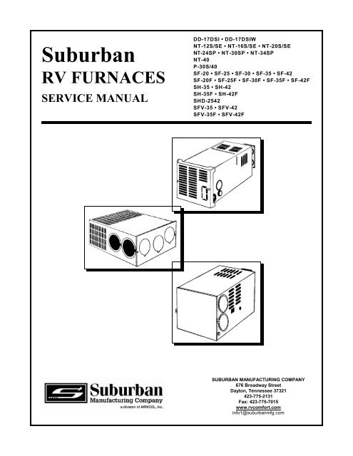
<strong>Suburban</strong><br />
<strong>RV</strong> FURNACES<br />
SE<strong>RV</strong>ICE MANUAL<br />
DD-17DSI • DD-17DSIW<br />
NT-12S/SE • NT-16S/SE • NT-20S/SE<br />
NT-24SP • NT-30SP • NT-34SP<br />
NT-40<br />
P-30S/40<br />
SF-20 • SF-25 • SF-30 • SF-35 • SF-42<br />
SF-20F • SF-25F • SF-30F • SF-35F • SF-42F<br />
SH-35 • SH-42<br />
SH-35F • SH-42F<br />
SHD-2542<br />
SFV-35 • SFV-42<br />
SFV-35F • SFV-42F<br />
SUBURBAN MANUFACTURING COMPANY<br />
676 Broadway Street<br />
Dayton, Tennessee 37321<br />
423-775-2131<br />
Fax: 423-775-7015<br />
www.rvcomfort.com<br />
info1@suburbanmfg.com
TABLE OF CONTENTS<br />
Page<br />
General <strong>Service</strong> Information...........................................................3<br />
<strong>Furnace</strong> Spec Sheet.................................................................4<br />
Installation ........................................................................5<br />
Vent Assembly Illustrations ........................................................ 6-16<br />
Return Air Illustrations ..............................................................16<br />
Ducting Illustrations ................................................................17<br />
Installation Requirements (DD, NT and P Model <strong>Furnace</strong>s) . . . . . . . . . . . . . . . . . . . . . . . . . . . . . . . . . 18<br />
Installation Requirements (SF, SH and SHD-2542 Model <strong>Furnace</strong>s) . . . . . . . . . . . . . . . . . . . . . . . . . . 19<br />
Installation Requirement (SFV Model <strong>Furnace</strong>s) ..........................................20<br />
<strong>Furnace</strong> Specifications (DD, NT and P Model <strong>Furnace</strong>s) . . . . . . . . . . . . . . . . . . . . . . . . . . . . . . . . . . . 21<br />
<strong>Furnace</strong> Specifications (SF, SFV, SH, and SHD-2542 Model <strong>Furnace</strong>s) . . . . . . . . . . . . . . . . . . . . . . . 22<br />
Sequence of Operation (Time Delay Relay Equipped <strong>Furnace</strong>s) . . . . . . . . . . . . . . . . . . . . . . . . . . . . . 23<br />
Sequence of Operation (Fan Control Module Board (520820) Equipped <strong>Furnace</strong>s) . . . . . . . . . . . . . . . 24<br />
Sequence of Operation (24 VAC Fan Control Module Board (520947) . . . . . . . . . . . . . . . . . . . . . . . . . 25<br />
Sequence of Operation (SHD-2542 Furance) ............................................26<br />
Trouble Shooting Flow Chart (<strong>Furnace</strong>s Equipped with Time Delay Relay) . . . . . . . . . . . . . . . . . . . . . 27<br />
Trouble Shooting Flow Chart (<strong>Furnace</strong>s Equipped with Fan Control Module Board) . . . . . . . . . . . . . . 28<br />
<strong>Service</strong> Hints, Diagnosis and Corrective Measures<br />
for <strong>Suburban</strong> 24-Volt AC Electronic Ignition <strong>Furnace</strong>s . . . . . . . . . . . . . . . . . . . . . . . . . . . . 29-30<br />
Wiring Diagrams................................................................ 30-34<br />
<strong>Furnace</strong> Removal ............................................................... 35-36<br />
SF, SH and SHD-2542 Electrode Gap Specifications & Positioning . . . . . . . . . . . . . . . . . . . . . . . . . . . 37<br />
NT and Park Model Electrode Gap Specifications & Positioning . . . . . . . . . . . . . . . . . . . . . . . . . . . . . 38<br />
Maintenance ......................................................................39<br />
Cautions & Safety Information ................................................ Back Cover<br />
NOTE: Our service technicians are available to assist you in making repairs or parts replacements<br />
from 8:00 a.m. to 5:00 p.m. Eastern Standard Time, Monday through Friday (except holidays), by<br />
calling 423-775-2131 extension 7102. E-mail address: info1@suburbanmfg.com<br />
2
GENERAL SE<strong>RV</strong>ICE INFORMATION<br />
<strong>Suburban</strong> DYNATRAIL furnaces installed in recreational vehicles are classified as Direct Vent Sealed Combustion<br />
<strong>Furnace</strong>s. A forced draft furnace utilizes a sealed combustion chamber which is vented to the outside atmosphere.<br />
The intake air for combustion is also taken from outdoors and is completely isolated from the room air. A motor is used<br />
to drive an impeller wheel to draw intake air into the chamber to support combustion and force the exhaust gases<br />
through the furnace chamber to the outside atmosphere. A second impeller wheel (driven by the same motor yet totally<br />
isolated from the combustion air) is used to circulate room air across the furnace chamber where it is heated. The<br />
blower then forces the hot air into the living area either through a duct system or through a front grille on the furnace<br />
cabinet on direct discharge models.<br />
<strong>Suburban</strong> furnaces operate on 12-volt DC power which is supplied either by a 12-volt battery or a converter system.<br />
A recreational vehicle furnace that is specifically designed for “park model” trailers operates on 120 volts AC. These<br />
are designed and tested under the same standards as the 12-volt models.<br />
<strong>Suburban</strong> forced draft combustion furnaces used in recreational vehicles are designed for use with Propane gas.<br />
Although a few recreational vehicle furnaces are approved for use with natural gas, one should never attempt to<br />
convert such a unit to natural gas unless the conversion is approved by the manufacturer of the furnace.<br />
Gas Supply Pressure Requirements<br />
Line Pressure:<br />
Minimum 11" WC*, Maximum 14" WC<br />
*WC - water column<br />
Voltage Requirements<br />
Voltage DC: 12 volt D.C.<br />
Minimum 10.5 volts D.C., Maximum 13.5 volts D.C.<br />
<strong>Service</strong> Tools Required<br />
Manometer gauge/ U-Tube<br />
Volt ohm meter capable of testing above 15 amps<br />
Module board tester #641511<br />
Gas leak detector OR approved leak check liquid<br />
Assorted wrenches<br />
Assorted hand tools<br />
Safety glasses<br />
3
<strong>Suburban</strong><br />
<strong>RV</strong> FURNACES<br />
12 VDC Direct BTU/h Shipping<br />
Discharge Input Height Width Depth Ignition Weight<br />
NT-12SE 12,000 9 3/8" 9 3/8" 21-27 3/4" Electronic 27<br />
NT-16SE 16,000 9 3/8" 9 3/8" 21-27 3/4" Electronic 27<br />
NT-20SE 19,000 9 3/8" 9 3/8" 21-27 3/4" Electronic 27<br />
DD-17DSI 17,000 12" 10 1/2" 22-29" Electronic 25<br />
Accessories Description<br />
260197 Vent Kit 2" - 4" DD Models<br />
260198 Vent Kit 4" - 6" DD Models<br />
260199 Vent Kit 6" - 9" DD Models<br />
12 VDC Ducted BTU/h Shipping<br />
<strong>Furnace</strong>s Input Height Width Depth Ignition Weight<br />
NT-12S 12,000 9 3/8" 9 3/8" 22 3/4-29 1/2" Electronic 27<br />
NT-16S 16,000 9 3/8" 9 3/8" 22 3/4-29 1/2" Electronic 27<br />
NT-20S 19,000 9 3/8" 9 3/8" 23 3/8-30 1/8" Electronic 27<br />
NT-24SP 24,000 12 1/2" 12" 23" Electronic 40<br />
NT-30SP 30,000 12 1/2" 12" 23" Electronic 40<br />
NT-34SP 34,000 12 1/2" 12" 23" Electronic 40<br />
NT-40 40,000 12 1/2" 12" 23" Electronic 42<br />
SF-20F 20,000 7 1/2" 17" 20" Electronic 35<br />
SF-25F 25,000 7 1/2" 17" 20" Electronic 35<br />
SF-30F 30,000 7 1/2" 17" 20" Electronic 35<br />
SF-35F 35,000 7 1/2" 17" 20" Electronic 35<br />
SF-42F 40,000 7 1/2" 17" 20" Electronic 35<br />
SH-35F 35,000 9 1/4" 17" 20" Electronic 40<br />
SH-42F 40,000 9 1/4" 17" 20" Electronic 42<br />
SF-20* 20,000 7 1/2" 17" 20" Electronic 35<br />
SF-25* 25,000 7 1/2" 17" 20" Electronic 35<br />
SF-30* 30,000 7 1/2" 17" 20" Electronic 35<br />
SF-35* 35,000 7 1/2" 17" 20" Electronic 35<br />
SF-42* 40,000 7 1/2" 17" 20" Electronic 35<br />
SH-35* 35,000 9 1/4" 17" 20" Electronic 40<br />
SH-42* 40,000 9 1/4" 17" 20" Electronic 42<br />
SHD-2542 25/40,000 9 1/4" 17" 20" Electronic 44<br />
Accessories<br />
6258ACW<br />
6258APW<br />
6267ACW<br />
Description<br />
*Door, Optional Access, Colonial White, Standard SF Models<br />
*Door, Optional Access, Polar White, Standard SF Models<br />
*Door, Optional Access, Colonial White, Standard SH Models<br />
120 VAC Park BTU/h Shipping<br />
Model <strong>Furnace</strong>s Input Height Width Depth Ignition Weight<br />
P-40 40,000 12 1/2" 12" 23" Electronic 46<br />
Accessories Description<br />
050733 Duct Cover<br />
050715 Duct Collar 4"<br />
051240 Duct Collar 2"<br />
280552 Rain Shield<br />
062164 Bottom Duct Gasket, NT-24/30/34SP, NT-40, P40<br />
070853 Bottom Duct Gasket, SF Models Except SF-42, (F)<br />
520009 Bottom Duct Kit W/Gasket, NT-24/30/34SP, NT-40. P40<br />
520576 Bottom Duct Kit W/Gasket, SF Models Except SF-42, (F), SH35 (F)<br />
520753 Bottom Duct Kit W/Gasket and Door, SF-42, (F)<br />
520864 Bottom Duct Kit W/Gasket SH-42 (F) SHD-2542<br />
Wall Thermostats are included with All Models, except SF.<br />
Vent Assemblies are included with all units, except DD.<br />
4
INSTALLATION<br />
There are several important aspects of the installation which will pertain to all <strong>Suburban</strong> forced draft furnaces, regardless of the model or the<br />
method in which they are installed. They are:<br />
1. Selecting a Location<br />
2. Venting<br />
3. Return Air<br />
4. Ducting<br />
Refer to the furnace installation manual for all installation requirements.<br />
Location and Installation- Locate the furnace near lengthwise center of the coach. Choose a location for installation out of the way of wires,<br />
pipes, etc. which might interfere with the installation. Adhere to the minimum clearances from cabinet to combustible construction as<br />
listed in the installation manual for your specific furnace model. Secure furnace cabinet to the floor of the coach using the holes<br />
provided in the furnace cabinet.<br />
Figure 1<br />
5
VENTING<br />
Venting- By definition of a Direct Vent Sealed Combustion <strong>Furnace</strong>, it must be vented to the outside atmosphere and also draw combustion air<br />
from outdoors. Therefore, it is imperative that the vent be unobstructed and there must be a seal between the exhaust and intake (caulking) . Refer<br />
to the vent assembly installation in the manual. The vent must be straight. There can be no offsets or turns in the vent. All vent tubes which<br />
connect to the furnace exhaust and intake must overlap a minimum of 1/2" on intake, and 1 1/4" on exhaust. Check your furnace model<br />
number for vent installation procedures. Vents cannot be altered as supplied from the factory.<br />
VENT ASSEMBLY INSTALLATION (SF and SH SERIES)<br />
Figure 2<br />
SF<br />
Figure 2A<br />
SH<br />
6
VENT ASSEMBLY INSTALLATION (SF and SH SERIES)<br />
Figure 3<br />
SF<br />
Figure 3A<br />
SH and SHD-2542<br />
7
VENT ASSEMBLY INSTALLATION (SF and SH SERIES)<br />
Figure 4<br />
SF<br />
Figure 4A<br />
SH<br />
8
VENT ASSEMBLY INSTALLATION (SFV)<br />
Figure 5<br />
Figure 5A<br />
9
Figure 6<br />
Figure 6A<br />
10
VENT ASSEMBLY INSTALLATION (DD SERIES)<br />
Note: Vent cap must be installed on DD furnace when bench testing.<br />
Figure 7<br />
11
VENT ASSEMBLY INSTALLATION (NT SERIES)<br />
Figure 8<br />
NT-12/16/20SE<br />
Figure 9<br />
NT-12/16/20S and SE<br />
Figure 10<br />
NT-12/16S<br />
12
VENT ASSEMBLY INSTALLATION (NT SERIES)<br />
Figure 11<br />
NT-20S<br />
Figure 12<br />
NT-24/30/34SP<br />
P-30S<br />
13
VENT ASSEMBLY INSTALLATION (NT SERIES)<br />
Figure 13<br />
NT-24/30/34SP<br />
P-30<br />
EXTENSION TUBE<br />
KIT NUMBER<br />
MIN./MAX. LENGTH<br />
(Extension Tube Range)<br />
520498 2-1/4" to 3-1/8"<br />
520499 3-1/8" to 4-7/8"<br />
520500 4-7/8" to 7"<br />
520501 7" to 9"<br />
Figure 14<br />
NT-24/30/34SP<br />
P-30S<br />
EXTENSION TUBE<br />
KIT NUMBER<br />
MIN./MAX. LENGTH<br />
(Extension Tube Range)<br />
520593 2-1/4" to 3-1/8"<br />
520594 3-1/8" to 4-7/8"<br />
520595 4-7/8" to 7"<br />
520596 7" to 9"<br />
Figure 15<br />
NT-40<br />
P-40<br />
14
VENT ASSEMBLY INSTALLATION (NT-40 and P-40)<br />
Figure 16<br />
NT-40<br />
Figure 17<br />
P-40<br />
15
Figure 18<br />
NT-40<br />
P-40<br />
RETURN AIR<br />
Return Air - The cabinet that the furnace may be installed in will have louvers or openings for the return air back to<br />
the furnace. When the furnace is installed, it is imperative that the return air louvers on the furnace cabinet opening<br />
are not obstructed.<br />
Usually, these furnaces are installed under a counter, sofa or bed in order to be out of the way. A grille or opening must<br />
be built into the cabinetry or into the base area of the sofa or bed. Return air from the living area of the trailer is drawn<br />
in through the grille and into the return air openings in the furnace cabinet. Figure 19 illustrates the return air circulation<br />
of the furnace. Note: Refer to the installation manual for the minimum return air area for your specific furnace<br />
model.<br />
Insufficient return air will cause the furnace to overheat and cycle on limit. Another symptom of a return air problem<br />
is:<br />
1. <strong>Furnace</strong> seems to run continuously in an effort to satisfy the thermostat.<br />
*THE TOTAL, FREE, UNOBSTRUCTED RETURN AIR OPENING<br />
TO THE FURNACE MUST NOT BE LESS THAN THE MINIMUM<br />
Figure 19<br />
16
DUCTING<br />
Ducting - <strong>Suburban</strong> furnaces require that a minimum duct area be maintained throughout entire duct system including<br />
through the register. It is very important to adhere to the minimum duct area in order to keep the furnace from cycling<br />
on high limit and to assure proper operation of the sail switch (sometimes referred to as a microswitch.) NOTE: (Refer<br />
to the installation manual for the minimum ducted square inches area for each model.)<br />
NOTE: Ducts terminating in a dead air space (like holding tank compartments or cargo areas (Toy Boxes) with<br />
no means for return air recirculation should not be counted in the required duct area. Also, ducts 2" in<br />
diameter or smaller should not be counted in the required duct area.<br />
W hen installing a duct system, avoid making a lot of turns. The straighter the duct system, the less the resistance to<br />
air flow and the better the performance of the furnace.<br />
Avoid making sharp turns in the duct system. Sharp turns will increase the static pressure in the plenum area of the<br />
furnace and could cause the furnace to cycle on limit.<br />
The duct connections to the furnace cabinet should be tight to eliminate any heat loss which could result in overheating<br />
of the component parts on the furnace as well as a reduction in the heated air flow through the ductwork.<br />
Figure 20<br />
17
DD-17DSI See *1 0" 0" 0" 0" 0" n/a n/a n/a n/a n/a<br />
NT-12S 3/8" 1" 0" 0" 1" 1" 2-4" n/a n/a 25" 55"<br />
NT-16S 3/8" 1" 0" 0" 1" 1" 2-4" n/a n/a 25" 55"<br />
NT-20S 1" 1" 0" 0" 1" 1" 2-4" n/a n/a 25" 55"<br />
NT-12SE See *1 5/8" 0" 0" 5/8" 5/8" n/a n/a n/a n/a n/a<br />
NT-16SE See *1 5/8" 0" 0" 5/8" 5/8" n/a n/a n/a n/a n/a<br />
NT-20SE See *1 5/8" 0" 0" 5/8" 5/8" n/a n/a n/a n/a n/a<br />
NT-24SP 0" 0" 0" 0" 1" 1" 3-4" 48" n/a 36" 55"<br />
NT-30SP 0" 0" 0" 0" 1" 1" 3-4" 48" n/a 36" 55"<br />
NT-34SP 0" 0" 0" 0" 2" 2" 4-4" 48" n/a 48" 55"<br />
Return Air<br />
Sq inch<br />
NT-40 1" 1" 0" 0" 2" 2" 4-4" 48" n/a 48" 113"<br />
P-30 0" 0" 0" 0" 1" 1" 4-4" 48" n/a 48" 55"<br />
P-40 1" 1" 0" 0" 2" 2" 4-4" 48" n/a 48" 113"<br />
INSTALLATION REQUIREMENTS<br />
Models<br />
Clr Front Clr<br />
Top<br />
Clr<br />
Btm<br />
Clr<br />
Back<br />
Clr<br />
Left<br />
Clr<br />
Right<br />
Ducts Req’d Btm Duct<br />
Sq Inch<br />
Top Duct<br />
Sq Inch<br />
L & R Side Duct<br />
Sq Inch<br />
*1 - Special clearances for discharge grills. Refer to Installation and Instruction <strong>Manual</strong>.<br />
*2 - Return air should be 142" if 4 ducts are used. May be reduced to 88" if 5 ducts are used.<br />
NOTE: 0" clearance is to spacer (flanges)
SF-20/20F 1" 0" 0" 0" 0" 0" 2-4" 56" 56" 25" 55"<br />
SF-25/25F 1" 0" 0" 0" 0" 0" 3-4" 56" 56" 36" 55"<br />
SF-30/30F 1" 0" 0" 0" 0" 0" 3-4" 56" 56" 36" 55"<br />
SF-35/35F 1" 0" 0" 0" 0" 0" 4-4" 56" 56" 48" 55"<br />
Return Air<br />
Sq inch<br />
SF-42/42F 1" 1" 0" 0" 2" 2" 4-4" 72" SEE *3 56" 48" SEE *2<br />
SH-35 1" 0" 0" 0" 1" 1" 4-4" 56" 56" 48" 55"<br />
SH-42 1" 1" 0" 0" 2" 2" 4-4" 72" SEE *3 56" 48" See *2<br />
SHD-2542 1" 1" 0" 0" 2" 2" 4-4" 72" SEE *3 56" 48" SEE *2<br />
INSTALLATION REQUIREMENTS<br />
Models<br />
Clr Front Clr<br />
Top<br />
Clr<br />
Btm<br />
Clr<br />
Back<br />
Clr<br />
Left<br />
Clr<br />
Right<br />
Ducts Req’d Btm Duct<br />
Sq Inch<br />
Top Duct<br />
Sq Inch<br />
L & R Side Duct<br />
Sq Inch<br />
NOTE: 0" clearance is to spacer (flanges)<br />
*1 - Special clearances for discharge grills. Refer to Installation and Instruction <strong>Manual</strong>.<br />
*2 - Return air should be 142" if 4 ducts are used. May be reducted to 88" if 5 ducts used.<br />
*3- Bottom duct required. SF42 uses kit # 520753, SH-42 and SHD-2542 uses kit #520864.
SFV-20/20F 1" 1" 0" 0" 1" 1" SEE *4 52" SEE *4 SEE *4 55"<br />
SFV-25/25F 1" 1" 0" 0" 1" 1" SEE *4 52" SEE *4 SEE *4 55"<br />
SFV-30/30F 1" 1" 0" 0" 1" 1" SEE *4 52" SEE *4 SEE *4 55"<br />
SFV-35/35F 1" 1" 0" 0" 1" 1" SEE *4 52" SEE *4 SEE *4 55"<br />
Return Air<br />
Sq inch<br />
SFV-42/42F 1" 2" 0" 0" 1" 1" SEE *4 52" SEE *4 SEE *4 142"<br />
NOTE: 0" clearance is to spacer (flanges)<br />
*1 - Special clearances for discharge grills. Refer to Installation and Instruction <strong>Manual</strong>.<br />
*2 - Return air should be 142" if 4 ducts are used. May be reducted to 88" if 5 ducts used.<br />
*3- Bottom duct required. SF42 uses kit # 520753, SH-42 and SHD-2542 uses kit #520864.<br />
*4- Vertical mount furnace review table below for ducting requirements. The duct requirements must be followed in order to assure proper operation of the furnace. The minimum open duct areas listed below must be<br />
maintained through the entire duct system including through register.<br />
INSTALLATION REQUIREMENTS<br />
Models<br />
Clr Front Clr<br />
Top<br />
Clr<br />
Btm<br />
Clr<br />
Back<br />
Clr<br />
Left<br />
Clr<br />
Right<br />
Ducts Req’d Btm Duct<br />
Sq Inch<br />
Top Duct<br />
Sq Inch<br />
L & R Side Duct<br />
Sq Inch<br />
MODEL<br />
TOP AND FRONT<br />
DUCTS<br />
(4" Round)<br />
BOTTOM LEFT<br />
DUCT<br />
RIGHT<br />
DUCT<br />
Minimum<br />
Duct Area<br />
Minimum<br />
Duct Area<br />
SFV-20(F) *Optional Required 52<br />
SQ. IN.<br />
SFV-25(F) *Optional Required 52<br />
SQ. IN.<br />
SFV-30(F) *Optional Required 52<br />
SQ. IN.<br />
SFV-35(F) 48 SQ. IN. (Bottom<br />
Front Duct Not To be<br />
Used)<br />
SFV-42(F) 48 SQ. IN. (Top Front<br />
Duct Not To Be<br />
Used.)<br />
Minimum<br />
Duct Area<br />
52 SQ. IN. 56 SQ. IN.<br />
*Optional *Optional<br />
*Optional *Optional<br />
*Optional *Optional<br />
52 SQ. IN. 56 SQ. IN. 72 SQ. IN.<br />
*Use of these ducts are in addition to the required use of the bottom duct.
FURNACE SPECIFICATIONS<br />
12 VDC<br />
Model<br />
Description<br />
Input<br />
BTU/hr<br />
Type Gas<br />
Voltage<br />
Motor<br />
Diameter<br />
Amp Draw<br />
Static<br />
Pressure<br />
C.F.M.<br />
Max.<br />
DD-17DSI<br />
Direct<br />
Discharge<br />
17,000 PROPANE 12 VDC 3" 2.9 n/a 145<br />
NT-12S<br />
NT-12SE<br />
Ducted<br />
Direct<br />
Discharge<br />
12,000 PROPANE 12 VDC 3" 2.8 S - .1" wc<br />
SE - n/a<br />
S - 122<br />
SE -140<br />
NT-16S<br />
NT-16SE<br />
Ducted<br />
Direct<br />
Discharge<br />
16,000 PROPANE 12 VDC 3" 2.8 S - .1" wc<br />
SE - n/a<br />
S - 165<br />
SE-140<br />
NT-20S<br />
NT-20SE<br />
Ducted<br />
Direct<br />
Discharge<br />
19,000 PROPANE 12 VDC 3" 2.8 S - .1" wc<br />
SE-n/a<br />
S - 165<br />
SE-150<br />
NT-24SP Ducted 24,000 PROPANE 12 VDC 2.5" 3.5 .2" wc 265<br />
NT-30SP Ducted 30,000 PROPANE 12 VDC 2.5" 5.5 .2" wc 345<br />
NT-34SP Ducted 34,000 PROPANE 12 VDC 2.5" 7.5 .1" wc 373<br />
NT-40 Ducted 40,000 PROPANE 12 VDC 2.5" 9.5 .155"/.20B 441<br />
Park<br />
Models<br />
P-30S<br />
Ducted 30,000 PROPANE 120 VAC 3" 2.5 .15" wc 345<br />
NOTES<br />
P-40** Ducted 40,000 PROPANE 120 VAC 3" 2.0 .15" wc 441<br />
**P-40 Park Model <strong>Furnace</strong> and valve is convertible to Natural Gas. Instructions on converting unit to Natural Gas are on sticker on side of cabinet.<br />
21
FURNACE SPECIFICATIONS<br />
12 VDC<br />
Model<br />
Description<br />
Input<br />
BTU/hr<br />
Type Gas<br />
Voltage<br />
Motor<br />
Diameter<br />
Amp Draw<br />
Static<br />
Pressure<br />
C.F.M.<br />
Max.<br />
SF-20/20F Ducted 20,000 PROPANE 12 VDC 3" 6.5=2.5 in.<br />
Motor<br />
8.5=3 in.<br />
Motor<br />
SF-25/25F Ducted 25,000 PROPANE 12 VDC 3" 6.5=2.5 in.<br />
Motor<br />
8.5=3 in.<br />
Motor<br />
SF-30/30F Ducted 30,000 PROPANE 12 VDC 3" 6.5=2.5 in.<br />
Motor<br />
8.5=3 in.<br />
Motor<br />
SF-35/35F Ducted 35,000 PROPANE 12 VDC 3" 8.5=2.5 in.<br />
Motor<br />
9.4=3 in.<br />
Motor<br />
.2" wc 300<br />
.2" wc 300<br />
.2" wc 300<br />
.2" wc 375<br />
SF-42/42F Ducted 40,000 PROPANE 12 VDC 3" 11.5 .25" wc 430<br />
SFV-20/20F Ducted 20,000 PROPANE 12 VDC 3" 8.5 .2" wc 300<br />
SFV-25/25F Ducted 25,000 PROPANE 12 VDC 3" 8.5 .2" wc 300<br />
SFV-30/30F Ducted 30,000 PROPANE 12 VDC 3" 8.5 .2" wc 300<br />
SFV-35/35F Ducted 35,000 PROPANE 12 VDC 3" 9.4 .2" wc 375<br />
SFV-42/42F Ducted 40,000 PROPANE 12 VDC 3" 11.5 .25" wc 430<br />
SH-35/35F Ducted 35,000 PROPANE 12 VDC 3" 8.2 .2" wc 375<br />
SH-42/42F Ducted 40,000 PROPANE 12 VDC 3" 10.6 .25" wc 430<br />
SHD-2542 Ducted 25,000<br />
42,000<br />
PROPANE 12 VDC 3" 8.8 (Low)<br />
12 (High)<br />
.25" wc 430<br />
22
SEQUENCE OF OPERATION<br />
For <strong>Furnace</strong>s Equipped With Time Delay<br />
The thermostat controls the operating circuit to the furnace<br />
by reacting to room temperature to open and close a set of<br />
contact points which allows current to flow to the ON and<br />
OFF switch then to the relay.<br />
The relay receives the power and allows power to pass<br />
through to the switch within the relay. This is done by a<br />
heater coil within the relay which actuates a bi-metal disc<br />
closing the relay circuit.<br />
The power then flows to the motor and allows the blower to<br />
operate. One end of the motor shaft drives the room air<br />
wheel. The other end of the motor shaft drives the<br />
combustion air wheel that delivers the required air to the<br />
burner for combustion.<br />
The limit switch is an in-line device which protects the<br />
furnace from over heating conditions. The contacts in the<br />
limit switch open at a given temperature setting, shutting off<br />
power to the ignition system which controls the gas valve.<br />
As the room air wheel comes up to speed, air flow closes<br />
the sail switch completing the circuit. The sail switch is<br />
placed into the system as a safety to prove there is<br />
adequate air for combustion.<br />
The next operation is controlled by the Direct Spark<br />
Ignition, (DSI) system as power is applied to the DSI board.<br />
The system will do the following.<br />
1. The board has a timing circuit which allows the blower to<br />
purge the chamber of any products of combustion or gas.<br />
2. The board will then apply power to the gas valve. At the<br />
same time it produces a high voltage power supply to the<br />
electrode producing spark at the burner.<br />
3. The board will also confirm the presence of a flame. If<br />
the flame is not sensed after 7 seconds, the module will try<br />
two (2) more times and then go into lock-out. The flame is<br />
sensed through the spark wire and electrode.<br />
When the thermostat has reached the set point with the<br />
room air temperature, the contacts will open removing<br />
power from the controls. The blower will remain on until the<br />
relay opens and stops the motor.<br />
NOTE: On some models, sail switch is before limit<br />
switch.<br />
23
Sequence of Operation for Fan Control Module Board<br />
Part Number 520820<br />
Time Line<br />
Start<br />
Thermostat Calls<br />
for Heat<br />
15 Seconds Purge<br />
Cycle<br />
7 Seconds Ignition<br />
Cycle and Flame<br />
Sense<br />
nd<br />
rd<br />
2 and 3 Ignition<br />
Cycles if Required<br />
Description - Sequence of Events<br />
The wall thermostat controls the operation of the furnace by reacting to room<br />
temperature, this allows current to flow through the On/Off switch to the module board.<br />
The module board constantly checks for a minimum 9.5 volts. If there is not 9.5 volts,<br />
the module board will go into a stand by mode until adequate power is supplied. It will<br />
then resume normal operation.<br />
Upon a call from the thermostat, the module board thermostat circuit will go active. The<br />
sail switch circuit is verified as being open. The blower output is energized. Blower<br />
motor starts.<br />
The module board will then verify that the sail switch circuit is closed and motor is up<br />
to speed. If this circuit remains open for 30 seconds after the blower motor starts, the<br />
module board will go into lock out and shut down the blower motor.<br />
The module board checks that the gas valve relay contacts (which are located on the<br />
module board) are open before the ignition sequence starts.<br />
The board has a pre-purge timing circuit of (approximately 15 seconds). This allows the<br />
chamber to purge.<br />
The module board will energize the gas valve and enable the high voltage spark output<br />
to the electrode for 7 seconds of ignition time.<br />
The module board will then check for flame sense to verify successful lighting of the<br />
main burner flame. Sparking will then be terminated and the gas valve and blower<br />
outputs will remain energized.<br />
If ignition is successful the module board will monitor the flame sense, sail switch and<br />
limit switch circuits, and the thermostat inputs during the heating period.<br />
The flame is sensed through the spark wire and electrode. Therefore, it is essential that<br />
the electrode is properly positioned in the burner flame.<br />
3 Try Ignition Board<br />
If the flame is not sensed after seven (7) seconds, a second 15 second purge cycle will<br />
begin followed by a second Trial-For-Ignition sequence. After three (3) Trial-For-Ignition<br />
attempts with no ignition of the main burner, the module board will de-energize the gas<br />
valve immediately and blower will run for 3 minutes and then shutdown in lockout.<br />
Heating Cycle If during the heating cycle, the limit switch circuit opens and remains open for 5<br />
minutes, the module board will go into lock out and shut down the blower motor. If this<br />
occurs, the thermostat will need to be reset for the furnace to operate.<br />
90 Second Shut<br />
Down<br />
When the thermostat has reached its set point and the demand for heat ends, the gas<br />
valve will be de-energized and the flame will go out. The post purge period of 90<br />
seconds begins. When it times out, the blower motor output is removed, and the blower<br />
stops.<br />
24
Sequence of Operation for 24 VAC Fan Control Module Board<br />
Part Number 520947<br />
Time Line<br />
Start<br />
Thermostat Calls<br />
for Heat<br />
15 Seconds Purge<br />
Cycle<br />
7 Seconds Ignition<br />
Cycle and Flame<br />
Sense<br />
nd<br />
rd<br />
2 and 3 Ignition<br />
Cycles if Required<br />
Heating Cycle<br />
Description - Sequence of Events<br />
The wall thermostat controls the operation of the furnace by reacting to room<br />
temperature, this allows current to flow through the On/Off switch to the module board.<br />
The module board must have a minimum 18 volts for normal operation.<br />
Upon a call from the thermostat, the module board thermostat circuit will go active. The<br />
sail switch circuit is verified as being open. The blower output is energized. Blower<br />
motor starts.<br />
The module board will then verify that the sail switch circuit is closed and motor is up<br />
to speed. If this circuit remains open blower motor will run continuously until sail switch<br />
closes.<br />
The module board checks that the gas valve relay contacts (which are located on the<br />
module board) are open before the ignition sequence starts.<br />
The board has a pre-purge timing circuit of (approximately 15 seconds). This allows the<br />
chamber to purge.<br />
The module board will energize the gas valve and enable the high voltage spark output<br />
to the electrode for 7 seconds of ignition time.<br />
The module board will then check for flame sense to verify successful lighting of the<br />
main burner flame. Sparking will then be terminated and the gas valve and blower<br />
outputs will remain energized.<br />
If ignition is successful the module board will monitor the flame sense, sail switch and<br />
limit switch circuits, and the thermostat inputs during the heating period.<br />
The flame is sensed through the flame sence electrode. Therefore, it is essential that<br />
the electrode is properly positioned in the burner flame.<br />
3 Try Ignition Board<br />
If the flame is not sensed after seven (7) seconds, a second 15 second purge cycle will<br />
begin followed by a second Trial-For-Ignition sequence. After three (3) Trial-For-Ignition<br />
attempts with no ignition of the main burner, the module board will de-energize the gas<br />
valve immediately and blower will run for 90 seconds and then shutdown in lockout.<br />
If during the heating cycle, the limit switch circuit opens and remains open the gas valve<br />
will close and the blower motor will continue to run.<br />
90 Second Shut<br />
Down<br />
When the thermostat has reached its set point and the demand for heat ends, the gas<br />
valve will be de-energized and the flame will go out. The post purge period of 90<br />
seconds begins. When it times out, the blower motor output is removed, and the blower<br />
stops.<br />
25
1st Stage Call for Heat<br />
Sequence of Operations for SHD-2542<br />
The wall thermostat controls the operation of the dual stage furnace by reacting to room temperature. This allows current to<br />
flow through the On/Off switch to the Blower Speed Control Board then to the Module Board.<br />
The module board constantly checks for a minimum 9.5 volts. If there is not 9.5 volts, the module board will go into a standby<br />
mode until adequate power is supplied. It will then resume normal operation.<br />
Upon a call from the thermostat the first stage will be activated. The module board thermostat circuit will go active and the sail<br />
switch is verified as being open. The blower output is energized. The blower motor starts.<br />
15 Second Purge Cycle<br />
The module board will then verify that the sail switch circuit is closed and motor is up to speed. If this circuit remains open for<br />
30 seconds after the blower motor starts, the module board will go into lockout and shut down the blower motor.<br />
The module board checks that the gas valve relay contacts (located on the module board) are open before the igniting<br />
sequence starts.<br />
The board has a pre-purge timing circuit of approximately 15 seconds. This allows the combustion chamber to purge.<br />
7 Second Ignition Cycle and Flame Sense<br />
The module board will energize the gas valve and enable the high voltage spark output to the electrode for a seven second<br />
ignition period.<br />
The module board will then check for flame sense to verify successful lighting of the main burner flame. Sparking of the igniter<br />
is then terminated. The gas valve and blower outputs will remain energized.<br />
If ignition is successful the module board will monitor the flame sense, sail switch, and the limit switch circuits. The flame is<br />
sensed through the spark wire and electrode therefore, it is essential that the electrode is properly positioned in the burner<br />
flame.<br />
3 try Ignition Board<br />
If the flame is NOT sensed after seven (7) seconds, or if the unit fails to ignite, a second fifteen (15) purge cycle will begin<br />
followed by second trial for ignition sequence. After three (3) trial for ignition attempts with no ignition of the main burner, the<br />
module board will de-energize the gas valve immediately and the blower will run for three (3) minutes and then go into lockout<br />
mode.<br />
nd<br />
2 Stage Heating<br />
If during the thermostat cycle the demand for heat drops below the second stage thermostat setting ( 3 to 5 degrees variance<br />
depending on thermostat manufacturer), the blower speed control board will be energized. The blower speed control board<br />
will energize the additional gas valve solenoid and increase motor speed to the high position. <strong>Furnace</strong> will remain in the second<br />
stage operation until thermostat is satisfied.<br />
90 Second Shut Down<br />
W hen the thermostat has reached its set point and the demand for heat ends, the gas valve will be de-energized and the flame<br />
will go out. The post combustion purge period of 90 seconds begins. When it times out, the blower motor output is removed,<br />
and the blower stops.<br />
26
TROUBLE SHOOTING GUIDE<br />
SUBURBAN <strong>RV</strong> FURNACES with TIME DELAY<br />
12 VDC HEATING SECTION<br />
Thermostat closes<br />
<br />
<br />
Yes<br />
<br />
<br />
<br />
<br />
Approximately 10-20 seconds<br />
Blower is operating<br />
<br />
-No-<br />
-No-<br />
Check thermostat wire connections,<br />
contact points and the heat<br />
anticipator.<br />
No<br />
<br />
Check 12vdc at blue wire, check the<br />
amp draw to thermostat.<br />
No<br />
<br />
Check for shorts.<br />
Check components amperage.<br />
Yes<br />
-Yes-<br />
-Yes-<br />
-Yes-<br />
Clean points, secure loose<br />
connections, replace thermostat if<br />
Anticipator is shorted.<br />
Replace thermostat.<br />
Repair or replace connections or parts<br />
with higher than normal amp draw.<br />
Check for 12vdc at furnace -No- Check on/off switch on furnace<br />
Yes<br />
<br />
Check fuse or circuit breaker -No- Replace fuse/Reset breaker<br />
Yes<br />
<br />
Check for 12vdc at time delay relay and<br />
for 12vdc to red wire leading to the motor.<br />
Yes<br />
<br />
-No-<br />
Replace the time delay relay.<br />
Yes Check ground wire on terminal block. -No- Replace the motor.<br />
<br />
After 15 seconds the module<br />
creates spark and opens valve.<br />
-No-<br />
Check for 12vdc between red and<br />
yellow wires at the module board.<br />
-Yes-<br />
Check plug connection to the<br />
mModule-electrode and wire-spark gap 1/8 inch<br />
between probe and ground.<br />
<br />
No<br />
<br />
<br />
Check for 12vdc at limit switch,<br />
both sides.<br />
-Yes-<br />
Replace the sail switch.<br />
Yes<br />
No<br />
<br />
<br />
Check for 12vdc at sail switch<br />
both sides.<br />
-Yes-<br />
Replace the limit switch.<br />
<br />
Spark occurs for approximately<br />
7 seconds and main burner flame<br />
establishes.<br />
-No-<br />
No spark at the electrode<br />
-No-<br />
Replace the module.<br />
<br />
Yes<br />
<br />
Check for 12vdc at gas solenoid<br />
valve.<br />
-No-<br />
Replace the module.<br />
<br />
Yes<br />
<br />
<br />
Did the gas valve open.<br />
-No-<br />
Check gas pressure at the manifold or for<br />
restrictions in the burner orifice.<br />
<br />
Yes<br />
<br />
No<br />
<br />
Yes<br />
<br />
<br />
Check for restriction in<br />
combustion air Intake (wasps, etc.)<br />
No<br />
<br />
Is flame established.<br />
-No-<br />
Replace the gas valve.<br />
Check flame contact to electrode. Flame should<br />
be hard blue.<br />
Thermostat opens and the time delay<br />
operates the fan for the<br />
cool down cycle.<br />
-No-<br />
Replace the time delay relay.<br />
Yes<br />
System Ok<br />
NOTE: On some models, sail switch is before limit switch.<br />
27
TROUBLE SHOOTING GUIDE<br />
SUBURBAN <strong>RV</strong> FURNACE with FAN CONTROL MODULE BOARDS<br />
12 VDC HEATING SECTION<br />
Thermostat Closes<br />
<br />
<br />
Yes<br />
<br />
<br />
<br />
<br />
Blower is operating<br />
at call for heat.<br />
<br />
-No-<br />
-No-<br />
Check thermostat wire connections,<br />
contact points and the heat<br />
anticipator.<br />
No<br />
<br />
Check 12vdc at blue wire, check the<br />
amp draw to thermostat.<br />
No<br />
<br />
Check for shorts.<br />
Check components amperage.<br />
Yes<br />
-Yes-<br />
-Yes-<br />
-Yes-<br />
Clean points, secure loose<br />
connections, replace thermostat if<br />
anticipator is shorted.<br />
Replace thermostat.<br />
Repair or replace connections or parts<br />
with higher than normal amp draw.<br />
Check for 12vdc at furnace -No- Check on/off switch on furnace<br />
Yes<br />
<br />
Check fuse or circuit breaker -No- Replace fuse/Reset breaker.<br />
Yes<br />
<br />
Check for 12vdc at power terminal on<br />
module board and for 12vdc to red wire<br />
leading to the motor.<br />
Yes<br />
<br />
-No-<br />
Replace the module board<br />
after confirming motor operation.<br />
Yes Check ground wire on terminal block. -No- Replace the motor.<br />
<br />
Motor is operating<br />
Yes<br />
-No- Reset thermostat. Motor operating. Check<br />
for 12 vdc at blue wire on molex edge<br />
connector.<br />
<br />
-Yes-<br />
Verify voltage thru limit and sail switch to<br />
module board. If circuit remains open for 30<br />
seconds, module board will go into lockout and<br />
shut down motor. Reset thermostat. Replace<br />
defective part.<br />
After 15 seconds the module<br />
creates spark and opens valve.<br />
-No-<br />
Check for 12vdc between red and<br />
yellow wires at the module board.<br />
-Yes-<br />
Check plug connection to the<br />
module-electrode and wire-spark gap 1/8 inch<br />
between probe and ground.<br />
<br />
No<br />
<br />
<br />
Check for 12vdc at limit switch,<br />
both sides.<br />
-Yes-<br />
Replace the sail switch.<br />
Yes<br />
Spark occurs for approximately<br />
7 seconds and main burner flame<br />
establishes.<br />
<br />
<br />
No<br />
<br />
Check for 12vdc at sail switch<br />
both sides.<br />
-Yes-<br />
Replace the limit switch.<br />
-No- No spark at the electrode -No- Replace the module.<br />
<br />
Yes<br />
<br />
Check for 12vdc at gas solenoid<br />
valve.<br />
-No-<br />
Replace the module.<br />
<br />
Yes<br />
<br />
<br />
Did the gas valve open.<br />
-No-<br />
Check gas pressure at the manifold or for<br />
restrictions in the burner orifice.<br />
<br />
Yes<br />
<br />
No<br />
<br />
Yes<br />
Check for restriction in<br />
combustion air Intake (wasps, etc.)<br />
Replace the gas valve.<br />
<br />
No<br />
<br />
<br />
Is flame established.<br />
-No-<br />
Check flame contact to electrode. Flame should<br />
be hard blue.<br />
Thermostat opens and the module board<br />
operates the fan for the<br />
cool down cycle.<br />
Yes<br />
-No-<br />
Replace the module board<br />
System Ok<br />
28
SE<strong>RV</strong>ICE HINTS, DIAGNOSIS, AND CORRECTIVE MEASURES<br />
FOR THE IGNITION SYSTEMS OF<br />
SUBURBAN 24 VOLT ELECTRONIC IGNITION GAS FURNACES<br />
WITH TIME DELAY<br />
CAUTIONS:<br />
1. Never operate the furnace with the electrode wire disconnected nor with<br />
the electrode assembly removed from the furnace.<br />
2. Never use a screwdriver on any part of the electrode assembly<br />
while the furnace is in operation.<br />
3. Be certain that the spark from the electrode never reaches the flame<br />
sensor portion of the electrode assembly.<br />
4. Be sure the electrode assembly screws are snug at all times, especially<br />
after the electrode has been removed and reinstalled.<br />
5. If the module board is found to be defective, it must be replaced - it is not<br />
field repairable. Any attempts to repair the board may alter the board and<br />
cause it to operate in an unsatisfactory manner.<br />
6. Insure that the gap between electrode and ground is always 1/8". The<br />
gap between the flame sensor should be approximately twice the gap<br />
between electrode and ground to insure no sparking to sensor. Sparking<br />
to sensor will damage the module board.<br />
The electronic ignition system is made up of three main parts; the module<br />
board, the electrode assembly, and the electrode wire. The module board<br />
is the brain of the electronic ignition system and it has several functions.<br />
1. When the blower reaches approximately 75% of the normal r.p.m.<br />
and sufficient air flow is established, the sail switch engages and completes<br />
a 24 volt circuit through the limit switch to the module board.<br />
2. After a 12 - 18 second delay, 24 volt current will pass through the<br />
module board to the solenoid valve. The current to the valve opens it and<br />
allows gas to the main burner; simultaneously, the module board sends<br />
high voltage through the electrode wire to the electrode assembly. The<br />
voltage seeks a ground between electrode and ground probe and a spark<br />
occurs. The spark then ignites the main burner.<br />
3. The module board also performs the lockout function in cases where the<br />
spark fails to light the burner. When lockout occurs, the spark stops, the<br />
voltage from the module board to the gas valve is discontinued, and the<br />
valve closes. The unit will remain in lockout and the blower will continue to<br />
run until the thermostat is turned off. Turning the thermostat off disengages<br />
the lockout function of the module board. After the blower has stopped, the<br />
ignition sequence can be started again. The module will try three times for<br />
ignition before lockout.<br />
It is important to determine the type problem being experienced, then<br />
the proper checkout procedure can be made. The following is a list of<br />
problems, how to identify in which area the problem is located, and<br />
how to correct it.<br />
1. Electrode not sparking - with blower running and micro switch<br />
engaged, check the following:<br />
a. Check for proper voltage at module board after the blower motor<br />
reaches full r.p.m. If no voltage, check continuity through micro<br />
switch and limit switch. Also check wiring and wire connections.<br />
b. Voltage is present but no spark at electrode after 12 - 18 second<br />
delay, check electrode wire connections.<br />
c. Wire connections OK, but electrode wire does not show<br />
continuity through it - replace electrode wire.<br />
d. Electrode wire does show continuity through it - check electrode<br />
gap to be sure it is 1/8" maximum between electrode and<br />
ground. NOTE: Gap between sensor and ground must be twice<br />
electrode gap.<br />
e. Electrode gap OK - check electrode assembly for possible<br />
cracks or carbon on tip of electrode.<br />
f. Electrode OK - replace module board.<br />
2. Electrode sparking, but gas not coming through burner:<br />
a. Check to see if voltage is coming out of module board to gas<br />
valve after the 12 - 18 second delay. Check the wires in the<br />
molex connector to be sure they are intact and making contact<br />
with the module board. Check wire from the module board to<br />
valve for continuity. Wire and connections check OK - replace<br />
module board.<br />
b. Voltage is coming out of module board to gas valve, but gas<br />
valve does not open - replace gas valve.<br />
3. Electrode sparking and gas valve opening, but burner will not<br />
light:<br />
a. Check to see if gas is coming through to the burner. This can be<br />
accomplished by using a flow meter in the gas supply line. If no<br />
gas is coming through the burner, check for obstruction in gas<br />
line, in main burner orifice, or in main burner.<br />
b. Gas is coming through burner, but spark will still not ignite<br />
burner - check gas pressure.<br />
Line Pressure - Min. 11" W.C.*, Max. 14" W.C.<br />
To properly check pressure, first determine the line pressure, cycle<br />
furnace and check pressure drop on demand. The drop in pressure<br />
should not be more than ½" W.C. A drop of more than 1/2" would<br />
indicate a faulty regulator, a restriction in the gas line, or a pinched gas<br />
line. Excessive pressure drop could also be due to moisture<br />
contamination.<br />
c. Gas pressure OK - check for obstruction in main burner;<br />
check to be sure electrode is positioned approximately 1/4"<br />
above and directly over slots on the main burner - adjust<br />
electrode if necessary.<br />
d. Remove burner and check burner for obstructions. Clean as<br />
required.<br />
4. Burner ignites, but goes off and into lockout:<br />
a. Check to be certain that flame sensor is over slots in the main<br />
burner and that the main burner flame is burning against the tip<br />
of the flame sensor - adjust by bending sensor probe. NOTE:<br />
Sensor probe should be in the inner blue cone of the burner<br />
flame (approximately 1/4" t o 5/16" above burner).<br />
b. Burner still goes off and into lockout - check wire connections<br />
at flame sensor and at module board.<br />
c. Wire connections OK - check continuity through flame sensor<br />
wire.<br />
d. Continuity of flame sensor wire OK - check with micro amp<br />
meter in series with flame sensor and flame sensor wire to be<br />
certain that the flame sensor is generating at least seven<br />
micro amps within seven seconds after the burner is ignited.<br />
Connect meter as follows: (+) to sensor wire, (-) to sensor<br />
probe. Adjust position of sensor probe, check for carbon<br />
deposits on sensor probe if reading is less than seven micro<br />
amps.<br />
e. Flame sensor circuit generating at least seven micro amps,<br />
but burner still goes off and into lockout - replace module<br />
board.<br />
5. Repeated module board failures:<br />
a. Check to be certain that the electrode spark is not sparking<br />
against the flame sensor portion of the electrode assembly.<br />
b. Check to be sure module board or high voltage wires are not<br />
shorted to the chamber wrapper or other furnace parts.<br />
c. Be sure insulator covering the electrode wire connection on<br />
the coil of the module board is in place and insulator behind<br />
module board is in place.<br />
d. Make certain that the transformer voltage is within 24 - 30<br />
volts A.C.<br />
e. Be sure duct connections to furnace are airtight. Seal duct<br />
collar connections to furnace cabinet with duct tape, if<br />
necessary to prevent hot air leakage. No air leakage should<br />
exist anywhere in the duct system, especially at connections<br />
on furnace cabinet.<br />
f. Be sure sensor wire terminal is tightly affixed to sensor probe.<br />
g. Be sure high voltage electrode wire is in good condition and<br />
properly positioned onto pierce point electrode.<br />
29
6. Customer complains of unit going into lockout only once in<br />
a while:<br />
a. Thoroughly check electrode and burner relationship.<br />
b. Lockout can occur if the gas pressure fluctuates at the time the<br />
thermostat calls for heat. Pressure fluctuations can be caused<br />
by a malfunctioning gas bottle regulator, an obstruction or a kink<br />
in the gas line, or moisture in the gas bottle regulator or in the<br />
gas lines. It is difficult to check for these fluctuations that will not<br />
noticeably affect any other appliance in the coach. However,<br />
isolating the furnace from the coach gas system will determine<br />
if the gas system is responsible. This isolation procedure can be<br />
done by connecting a separate upright bottle, regulator and gas<br />
line directly to the furnace, eliminating the coach gas system. If<br />
the occasional lockout still exists, then the furnace should be<br />
thoroughly tested to determine the cause; however, if the<br />
furnace works properly on this separate system, then the coach<br />
gas system should be checked.<br />
c. Check furnace return air and warm air discharge to be certain<br />
sufficient air flow is present to engage micro switch every time.<br />
d. Check micro switch to be sure it moves freely.<br />
e. Remove electrode and burner. Clean thoroughly.<br />
f. When moisture in the gas system is suspected as being the<br />
problem, especially where the horizontal type gas bottle is being<br />
used, the following steps should be take to prepare the gas<br />
system against further moisture problems:<br />
Corrective Measures:<br />
1. Disconnect gas bottle and drain it completely dry of all gas<br />
and all moisture.<br />
2. Disconnect and blow out all gas lines completely dry.<br />
3. Check pressure regulator on the gas bottle. Replace if<br />
necessary.<br />
4. Add the drying agent. One half pint of methanol alcohol per<br />
100 pound bottle capacity is recommended.<br />
Precautions:<br />
5. Never fill the gas bottle over 80%.<br />
6. Do not use the gas bottle completely dry to avoid using up<br />
the drying agent.<br />
We have found the above procedures to be effective in solving<br />
most occasional lockout problems, especially where the<br />
horizontal type gas bottle is used. All of these steps must be<br />
performed as described for the preparation of a contaminated<br />
gas system to be 100% effective.<br />
Figure 21<br />
P-30S with Time Delay<br />
Figure 22<br />
P-40 with Time Delay<br />
30
Figure 23<br />
Remote Flame Sense<br />
With Time Delay<br />
Figure Local Flame 24 Sense<br />
(NT Models)<br />
With Time Delay<br />
Figure Fan Control 25 Board<br />
(SF-20/25/30/35/42F)<br />
31
Figure 28<br />
Fan Control Board<br />
(NT-24/30/34SP and NT-40)<br />
Figure 29<br />
Fan Control<br />
P-30S<br />
33
Figure 30<br />
Fan Control Board<br />
P-40<br />
34
FURNACE REMOVAL<br />
To replace parts or service the SUBURBAN family of <strong>RV</strong> furnaces, it is necessary to follow these steps:<br />
DD-17DSI<br />
1. Turn off gas and power, then disconnect gas and power supply at the furnace. Label wires as necessary.<br />
2. Remove the vent cap assembly by removing applicable screws.<br />
3. Remove the cabinet front two (2) screws.<br />
4. Remove the applicable screws securing the furnace to the coach floor.<br />
5. Remove duct from side of furnace, if equipped.<br />
6. Remove the furnace from the cabinet area to gain access to combustion chamber and applicable parts.<br />
7. Some parts can be accessed without removal of the complete furnace.<br />
8. To re-install, reverse this procedure.<br />
9. Rewire applicable wires and perform a leak test on all fittings. Perform a drop pressure test.<br />
NT-12/16/20S<br />
1. Turn off gas and power, then disconnect gas and power supply at the furnace. Label wires as necessary.<br />
2. Remove the vent cap assembly by removing applicable screws.<br />
3. Remove the cabinet front two (2) screws.<br />
4. Remove the (1) one tie down screw securing the chamber to the cabinet.<br />
5. Remove the furnace from the cabinet by pulling chamber outward completely to gain access to all controls and applicable<br />
parts.<br />
6. To re-install, reverse this procedure.<br />
7. Rewire applicable wires and perform a leak test on all fittings. Perform a drop pressure test.<br />
NT-12/16/20SE<br />
1. Turn off gas and power, then disconnect gas and power supply at the furnace. Label wires as necessary.<br />
2. Remove the vent cap assembly by removing applicable screws.<br />
3. Remove the cabinet front two (2) screws.<br />
4. Remove the (2) two tie down screws securing the chamber to the cabinet.<br />
5. Remove the furnace from the cabinet by pulling chamber outward completely to gain access to all controls and applicable<br />
parts.<br />
6. To re-install, reverse this procedure.<br />
7. Rewire applicable wires and perform a leak test on all fittings. Perform a drop pressure test.<br />
NT-24/30/34SP and NT-40<br />
1. Turn off gas and power, then disconnect gas and power supply at the furnace. Label wires as necessary.<br />
2. Remove the vent cap assembly by removing applicable screws and one (1) flue retaining screw. Not applicable to NT-40.<br />
3. Remove the cabinet front two (2) screws.<br />
4. Remove the (2) two tie down screws securing the chamber to the cabinet.<br />
5. Remove the furnace from the cabinet by pulling chamber outward completely to gain access to all controls and applicable<br />
parts.<br />
6. To re-install, reverse this procedure.<br />
7. Rewire applicable wires and perform a leak test on all fittings. Perform a drop pressure test.<br />
35
FURNACE REMOVAL<br />
SF-20/25/30/35/42, SFV-20/25/30/35/42, SH-35/42 and SHD-2542<br />
1. Remove the vent cap assembly from the outside access door by removing applicable screws, also the four (4)<br />
screws retaining the door to the frame. Remove the door to gain access to the furnace.<br />
2. Turn off gas and power, then disconnect gas and power supply at the furnace. Label wires as necessary.<br />
3. Remove the (1) one tie down screw securing the chamber to the cabinet.<br />
4. Remove the furnace from the cabinet by pulling chamber outward completely to gain access to all controls and<br />
applicable parts.<br />
5. To re-install, reverse this procedure.<br />
6. Rewire applicable wires and perform a leak test on all fittings. Perform a drop pressure test.<br />
SF-20/25/30/35/42F, SFV-20/25/30/35/42F and SH-35/42F<br />
1. Turn off gas and power, then disconnect gas and power supply at the furnace. Label wires as necessary.<br />
2. Remove the vent cap assembly by removing applicable screws.<br />
3. Remove the cabinet front two (2) screws.<br />
4. Remove the (1) one tie down screw securing the chamber to the cabinet.<br />
5. Remove the furnace from the cabinet by pulling chamber outward completely to gain access to all controls and applicable<br />
parts.<br />
6. To re-install, reverse this procedure.<br />
7. Rewire applicable wires and perform a leak test on all fittings. Perform a drop pressure test.<br />
P-30S and P-40<br />
1. Turn off gas and power, then disconnect gas and power supply at the furnace. Label wires as necessary.<br />
2. Remove the vent cap assembly by removing applicable screws and one (1) flue retaining screw. (Not applicable<br />
to P40.)<br />
3. Remove the cabinet front two (2) screws.<br />
4. Remove the (2) two tie down screw securing the chamber to the cabinet.<br />
5. Remove the furnace from the cabinet by pulling chamber outward completely to gain access to all controls and applicable<br />
parts.<br />
6. To re-install, reverse this procedure.<br />
7. Rewire applicable wires and perform a leak test on all fittings. Perform a drop pressure test.<br />
36
SF, SH AND SHD-2542 ELECTRODE GAP SPECIFICATIONS AND POSITIONING<br />
To assure consistent ignition of the burner, it is important for the electrode to be positioned properly over the top of the burner.<br />
W hen replacing the electrode, or should you be experiencing ignition type problems, the electrode should be positioned as<br />
outlined in the drawing.<br />
1. Remove the furnace chamber assembly from the furnace cabinet following instructions listed in the installation manual.<br />
2. Remove the burner access door. Manifold assembly will have to be removed at the valve. Remove the burner from the<br />
combustion chamber by removing six (6) screws which attach the burner to the chamber and air baffles (plates). Remove<br />
top air baffle and clip.<br />
3. Locate the lance in relation to the burner ports for electrode positioning by:<br />
a. Shine a flashlight into the burner venturi as illustrated (be sure the flashlight lens is against the end of the burner).<br />
b. Light will reflect off the lance in the venturi of the burner and shine through a position of the two (2) rows of burner<br />
ports in the top of the burner.<br />
c. Using a black felt-tip pen, mark a line along top of burner 3/16" from back of lance and parallel with lance. Make<br />
an additional mark indication center line of the lance. (See illustration). Both marks will be used later as reference<br />
marks; therefore, keep lines thin.<br />
4. Reassemble the burner into the chamber. Be sure the air baffles (plates) are positioned as removed. Mount center clip<br />
in place.<br />
5. Adjust electrode so the electrode probe is positioned along the marked center line of the burner lance and the tip of the<br />
electrode terminates 3/16" from the back of the lance (at the line marked in Step 3C). (See illustration).<br />
6. IMPORTANT: Be sure electrode probe maintains a 1/8" spark gap over the burner as illustrated.<br />
7. Reinstall burner access door and reconnect manifold. Manifold must be checked for leaks with unit operating, before<br />
installing in cabinet. Reinstall furnace into the cabinet following the instructions in the installation manual. Check all gas<br />
connections for leaks using proper leak test solution.<br />
Figure 31<br />
37
NT ELECTRODE GAP SPECIFICATIONS<br />
AND POSITIONING<br />
To assure consistent ignition of the burner, it is important for the electrode to be positioned properly over the top of the burner.<br />
When replacing the electrode, or should you be experiencing ignition type problems, the electrode should be positioned as<br />
outlined in the drawing.<br />
1. 1/8" spark gap between electrode and ground.<br />
2. Maintain electrode position of 3/16" over burner ports.<br />
Figure 32<br />
LOCAL FLAME SENSE<br />
PARK MODEL ELECTRODE GAP SPECIFICATIONS<br />
AND POSITIONING<br />
To assure consistent ignition of the burner, it is important for the electrode to be positioned properly over the top of the burner.<br />
W hen replacing the electrode, or should you be experiencing ignition type problems, the electrode should be positioned as<br />
outlined in the drawing.<br />
1. 1/8" spark gap between electrode and ground.<br />
2. 1/4" spark gap between ground and flame sensor.<br />
3. Maintain electrode position of 3/16" over burner ports.<br />
Figure 33<br />
REMOTE FLAME SENSE<br />
38
MAINTENANCE<br />
Preventative maintenance is essential if an <strong>RV</strong> owner is to have reliable, safe operation of his furnace. Two important areas<br />
to watch closely in order to assure safe, reliable operation are the venting and the main burner.<br />
An obstruction in the vent or main burner will reduce the combustion air which results in incomplete combustion. Whenever<br />
incomplete combustion occurs, the by-products are carbon monoxide (CO) and soot. If the furnace outside exhaust vent shows<br />
black soot forming, the furnace should not be operated until the problem is corrected. Two common causes are:<br />
1. Restriction in the vent or furnace intake (screens, wasp nests, tape).<br />
2. Dirty burner.<br />
If operation of the furnace continues under these conditions, it could result in serious injury to the occupants of the <strong>RV</strong> or even<br />
death.<br />
Cleaning of the main burner and an inspection of the venting system should be done at least once a year, preferably just before<br />
the beginning of the heating season. Some <strong>RV</strong> owners and service personnel have the false assumption that if a furnace has<br />
not been used, it will not require cleaning. NOT SO! A furnace which has not been used for some time could be more in need<br />
of cleaning than a furnace which has been used extensively.<br />
Dust and lint should be removed from the room air blower wheel and sail switch. A build up of dust and lint on the blower wheel<br />
can cause the motor to drag and not generate enough air flow to engage the sail switch. Dust accumulation on the sail switch<br />
will restrict the travel of the actuator arm to where the air flow across the paddle will not sail it in and complete the valve circuit.<br />
A yearly inspection should be made of all gaskets on the furnace. If any gaskets show signs of leakage or deterioration, they<br />
must be replaced.<br />
Figure 34<br />
Figure 35<br />
Figure 36<br />
Figure 37<br />
39
CAUTIONS & SAFETY INFORMATION<br />
1. Never use a battery charger to power or test an electronic ignition furnace as they sometimes provide more than<br />
14.5 DC Volts that could damage the module board.<br />
2. Never operate the furnace with the electrode wire disconnected nor with the electrode assembly removed<br />
from the furnace.<br />
3. Never use a screwdriver on any part of the electrode assembly while the furnace is in operation.<br />
4. Be certain that the spark from the electrode never reaches the flame sensor portion of the electrode assembly<br />
on remote sense units.<br />
5. Install the furnace so electrical components and connections are protected from water.<br />
6. Wire the furnace direct to the battery when possible.<br />
7. Use two wrenches on gas fittings when tightening gas connections.<br />
8. Verify voltage of furnace, do not use 120 volt AC with 12 volt DC.<br />
9. Do not modify the furnace in any way.<br />
10. Do not vent the furnace to an outside enclosed porch area or where the vent is covered or obstructed.<br />
11. Always meet or exceed minimum duct requirements. Also meet the minimum return air requirements.<br />
12. <strong>Furnace</strong> must be installed and vented correctly. Refer to the Installation <strong>Manual</strong> for the specific model furnace.<br />
13. Do not install aftermarket components.<br />
SUBURBAN MANUFACTURING COMPANY<br />
676 Broadway Street<br />
Dayton, Tennessee 37321<br />
423-775-2131<br />
Fax: 423-775-7015<br />
www.rvcomfort.com<br />
E-mail: info1@suburbanmfg.com<br />
2007