Belimo-Xref and Tech Guide - Kele
Belimo-Xref and Tech Guide - Kele
Belimo-Xref and Tech Guide - Kele
- No tags were found...

You also want an ePaper? Increase the reach of your titles
YUMPU automatically turns print PDFs into web optimized ePapers that Google loves.
<strong>Belimo</strong> Project: Hearst Tower,<br />
New York, New York<br />
Retrofi t Solutions<br />
EFFECTIVE APRIL 2013
Why Retrofi tting Makes Sense<br />
Valves <strong>and</strong> actuators are responsible for ensuring reliable functioning hydronic <strong>and</strong> air control HVAC systems all<br />
over the world. With innovative technology, verified quality <strong>and</strong> easy h<strong>and</strong>ling during installations <strong>and</strong> operation,<br />
they boost the performance <strong>and</strong> efficiency of integrated building technology.<br />
Are you in need of a solution for a broken linkage, leaky hydraulic actuator, non-functioning electric or pneumatic<br />
actuator Do you have a need for replacing a non-functioning application within a day or so<br />
<strong>Belimo</strong> provides airside <strong>and</strong> waterside retrofit application solutions, with direct coupled or remote access<br />
linkages, <strong>and</strong> efficient actuators.<br />
Damaged linkages <strong>and</strong>/or actuators resulting in non-functioning HVAC system applications used to mean a loss<br />
of properly functioning systems leading to a degradation of energy efficiency, consumer comfort, time, <strong>and</strong><br />
labor. Replacing a valve along with the actuator or trying to determine how to fix an airside linkage is not always<br />
a sensible solution. Taking a system off-line to replace various components is not only laborious, it’s expensive.<br />
Facilities can lose thous<strong>and</strong>s of dollars a day during maintenance shut-down. With retrofit solutions this problem<br />
simply goes away. Valves <strong>and</strong> damper applications can be quickly <strong>and</strong> conveniently restored without any<br />
interruption in service. In fact, entire systems can often be updated in a day. A poorly functioning or even nonfunctioning<br />
system can be transformed into a highly functioning, more efficient system.<br />
<strong>Belimo</strong> provides many retrofit solutions that are compatible with all major control systems, so there is no need<br />
to replace other system controls. MFT <strong>Tech</strong>nology is also available <strong>and</strong> can be reprogrammed to suit your<br />
controller needs with just one MFT model actuator.<br />
In addition, <strong>Belimo</strong>’s design team is ready <strong>and</strong> willing to customize a solution for non-st<strong>and</strong>ard retrofit solutions.<br />
Call <strong>Belimo</strong> at 800-543-9038 for assistance in fulfilling your retrofit application requirements.<br />
Hearst Tower, New York, NY Existing Installation Solution with No Down Time!
®<br />
Table of Contents<br />
RETROFIT SOLUTIONS<br />
How to Select an Actuator . . . . . . . . . . . . . . . . . . . . . . . . . . . . . . . . . . . . . . . . . . . . . . .3<br />
SOLUTIONS FOR SPECIFIC ACTUATOR MANUFACTURER AND PART NUMBERS<br />
Discontinued <strong>Belimo</strong> Products . . . . . . . . . . . . . . . . . . . . . . . . . . . . . . . . . . . . . . . . . . . . .5<br />
Replacement of Competitor Fire & Smoke Actuators . . . . . . . . . . . . . . . . . . . . . . . . . . . . . . . . . .8<br />
Honeywell . . . . . . . . . . . . . . . . . . . . . . . . . . . . . . . . . . . . . . . . . . . . . . . . . . . . . 11<br />
Invensys . . . . . . . . . . . . . . . . . . . . . . . . . . . . . . . . . . . . . . . . . . . . . . . . . . . . . 14<br />
Johnson Controls . . . . . . . . . . . . . . . . . . . . . . . . . . . . . . . . . . . . . . . . . . . . . . . . . . . 17<br />
Siemens . . . . . . . . . . . . . . . . . . . . . . . . . . . . . . . . . . . . . . . . . . . . . . . . . . . . . 20<br />
Specialized Retrofit Solutions . . . . . . . . . . . . . . . . . . . . . . . . . . . . . . . . . . . . . . . . . . . . . 22<br />
Non-Direct Coupled Retrofit Solutions . . . . . . . . . . . . . . . . . . . . . . . . . . . . . . . . . . . . . . . . 24<br />
Economizer Actuator Retrofit Solutions . . . . . . . . . . . . . . . . . . . . . . . . . . . . . . . . . . . . . . . . 26<br />
ZIP Economizer . . . . . . . . . . . . . . . . . . . . . . . . . . . . . . . . . . . . . . . . . . . . . . . . . . . . 27<br />
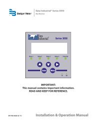
New Generation<br />
Globe Valve Actuator<br />
• Higher steam inlet rating up to<br />
100 psi.<br />
• Increased force ranges for higher<br />
close-off pressures.<br />
• Full selection of electronic fail <strong>and</strong><br />
non-fail-safe options.<br />
• Field selectable, fail-safe position<br />
with switch.<br />
• Modular order entry process for<br />
customizing fl exibility, e.g. cable<br />
length, run times, etc.<br />
GLOBE VALVE RETROFIT SOLUTIONS<br />
UGLK.../UGSP... Retrofit Linkage for Globe Valves . . . . . . . . . . . . . . . . . . . . . . . . . . . . . . . . . . 35<br />
New Generation Globe Valve Linkages . . . . . . . . . . . . . . . . . . . . . . . . . . . . . . . . . . . . . . . . 38<br />
New Generation Globe Valve Actuators . . . . . . . . . . . . . . . . . . . . . . . . . . . . . . . . . . . . . . . . 41<br />
UGSL1200 Short Stroke Valve Retrofit Kit . . . . . . . . . . . . . . . . . . . . . . . . . . . . . . . . . . . . . . 89<br />
How to Select a Globe Valve Retrofit Solution . . . . . . . . . . . . . . . . . . . . . . . . . . . . . . . . . . . . 90<br />
Globe Valve Retrofit Actuators . . . . . . . . . . . . . . . . . . . . . . . . . . . . . . . . . . . . . . . . . . . . 91<br />
SOLUTIONS FOR SPECIFIC MANUFACTURER AND PART NUMBERS<br />
Honeywell . . . . . . . . . . . . . . . . . . . . . . . . . . . . . . . . . . . . . . . . . . . . . . . . . . . . . 92<br />
Johnson Controls . . . . . . . . . . . . . . . . . . . . . . . . . . . . . . . . . . . . . . . . . . . . . . . . . . . 99<br />
Robertshaw . . . . . . . . . . . . . . . . . . . . . . . . . . . . . . . . . . . . . . . . . . . . . . . . . . . . 114<br />
Siebe - Invensys - Barber Colman . . . . . . . . . . . . . . . . . . . . . . . . . . . . . . . . . . . . . . . . . 114<br />
Siemens - L<strong>and</strong>is - Powers . . . . . . . . . . . . . . . . . . . . . . . . . . . . . . . . . . . . . . . . . . . . . 122<br />
Warren Controls . . . . . . . . . . . . . . . . . . . . . . . . . . . . . . . . . . . . . . . . . . . . . . . . . . 129<br />
Custom Globe Valve Solutions . . . . . . . . . . . . . . . . . . . . . . . . . . . . . . . . . . . . . . . . . . . 135<br />
Custom Globe Valve Retrofit Solution Form . . . . . . . . . . . . . . . . . . . . . . . . . . . . . . . . . . . . 136<br />
UGSP Series Globe Valve Retrofit Solution . . . . . . . . . . . . . . . . . . . . . . . . . . . . . . . . . . . . . 138<br />
UGLK Retrofit, Components . . . . . . . . . . . . . . . . . . . . . . . . . . . . . . . . . . . . . . . . . . . . 148<br />
Globe Valve Accessories . . . . . . . . . . . . . . . . . . . . . . . . . . . . . . . . . . . . . . . . . . . . . . 149<br />
P10406 - 04/13 - Subject to change. © <strong>Belimo</strong> Aircontrols (USA), Inc.<br />
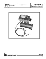
ZG-JSL Jackshaft Linkage<br />
• Simplifi es typical installations <strong>and</strong><br />
eliminates the diffi culties where<br />
jackshaft bearings are hard to access.<br />
• Unique open ended design <strong>and</strong> clamp<br />
insert accommodates any jackshaft<br />
½” to 1.05” in diameter.<br />
• Anti-rotation plate enables various<br />
actuators to be mounted <strong>and</strong> in<br />
multiple orientations.<br />
BUTTERFLY VALVE RETROFIT SOLUTIONS<br />
UFLK.../UFSP... Retrofi t Linkage for Butterfl y Valves . . . . . . . . . . . . . . . . . . . . . . . . . . . . . . . . 151<br />
How to Select a Butterfl y Valve Retrofi t Solution . . . . . . . . . . . . . . . . . . . . . . . . . . . . . . . . . . 155<br />
Butterfl y Valve Retrofi t Actuators . . . . . . . . . . . . . . . . . . . . . . . . . . . . . . . . . . . . . . . . . . 156<br />
SOLUTIONS FOR SPECIFIC MANUFACTURER AND PART NUMBERS<br />
<strong>Belimo</strong> . . . . . . . . . . . . . . . . . . . . . . . . . . . . . . . . . . . . . . . . . . . . . . . . . . . . 158<br />
Bray . . . . . . . . . . . . . . . . . . . . . . . . . . . . . . . . . . . . . . . . . . . . . . . . . . . . 159<br />
Centerline . . . . . . . . . . . . . . . . . . . . . . . . . . . . . . . . . . . . . . . . . . . . . . . . . . . . 160<br />
Flowseal . . . . . . . . . . . . . . . . . . . . . . . . . . . . . . . . . . . . . . . . . . . . . . . . . . . . 162<br />
Johnson Controls . . . . . . . . . . . . . . . . . . . . . . . . . . . . . . . . . . . . . . . . . . . . . . . . . . 163<br />
Keystone . . . . . . . . . . . . . . . . . . . . . . . . . . . . . . . . . . . . . . . . . . . . . . . . . . . . 164<br />
Milwaukee . . . . . . . . . . . . . . . . . . . . . . . . . . . . . . . . . . . . . . . . . . . . . . . . . . . . 166<br />
Nibco . . . . . . . . . . . . . . . . . . . . . . . . . . . . . . . . . . . . . . . . . . . . . . . . . . . . 168<br />
PDC . . . . . . . . . . . . . . . . . . . . . . . . . . . . . . . . . . . . . . . . . . . . . . . . . . . . 169<br />
Victualic . . . . . . . . . . . . . . . . . . . . . . . . . . . . . . . . . . . . . . . . . . . . . . . . . . . . 169<br />
SPECIALTY SOLUTIONS FOR VALVE MANUFACTURERS<br />
Apollo, Challenger, Chemtrol, Dezurik, FNW, Gruvlok,<br />
Hammond, Jamesbury, Jenkins, Metrafl ex, Mueller,<br />
Quartermaster, Watts . . . . . . . . . . . . . . . . . . . . . . . . . . . . . . . . . . . . . . . . . . . . . . . . 171<br />
Custom Butterfly Valve Retrofit Solution Form . . . . . . . . . . . . . . . . . . . . . . . . . . . . . . . . . . . 172<br />
Component Identification . . . . . . . . . . . . . . . . . . . . . . . . . . . . . . . . . . . . . . . . . . . . . . 174<br />
Valve Accessories . . . . . . . . . . . . . . . . . . . . . . . . . . . . . . . . . . . . . . . . . . . . . . . . . . 175<br />
BALL VALVE RETROFIT SOLUTIONS<br />
Custom Ball Valve Retrofi t Solution Form . . . . . . . . . . . . . . . . . . . . . . . . . . . . . . . . . . . . . . 178<br />
Component Identifi cation . . . . . . . . . . . . . . . . . . . . . . . . . . . . . . . . . . . . . . . . . . . . . . 180<br />
UBSP... Custom Retrofi t Linkages for Ball Valves . . . . . . . . . . . . . . . . . . . . . . . . . . . . . . . . . . 181<br />
<strong>Belimo</strong> Platinum Distributors . . . . . . . . . . . . . . . . . . . . . . . . . . . . . . . . . . . . . . . . inside back cover
Retrofit <strong>and</strong> Replacement<br />
How to Select an Actuator for Damper Retrofit<br />
®<br />
The “10 questions” method for sizing <strong>and</strong> selection shown below is<br />
recommended as the best method for your actuation requirements.<br />
Use the “Application Data” column in this chart as a worksheet to help<br />
in the selection process.<br />
APPLICATION INFO<br />
1<br />
2<br />
3<br />
4<br />
5<br />
What is the<br />
total area of<br />
the damper<br />
Opposed blade<br />
or Parallel<br />
blade control<br />
construction<br />
Are there blade<br />
<strong>and</strong> edge seals<br />
on the damper<br />
For the damper<br />
in question,<br />
what does the<br />
manufacturer<br />
specify as the<br />
torque rating<br />
What is the air<br />
velocity, static<br />
pressure, or<br />
design CFM<br />
L” x W” = Total sq<br />
inches/144 = total sq feet<br />
Opposed Blade<br />
w/o seals 3 in-lbs/sq feet*<br />
Opposed Blade<br />
w/ seals 5 in-lbs/sq feet<br />
Parallel Blade<br />
w/o seals 4 in-lbs/sq feet<br />
Parallel Blade<br />
w/ seals 7 in-lbs/sq feet<br />
*Less than 1,000 feet per<br />
minute<br />
This will impact<br />
the proper<br />
selection as the<br />
seals add resistance<br />
requiring more torque.<br />
If unknown, use<br />
a worst case<br />
scenario, parallel<br />
blade with seals.<br />
If this information<br />
is not available<br />
refer to the<br />
“typical damper<br />
requirements <strong>and</strong><br />
sizing” chart<br />
below.<br />
Systems above 1,000 FPM<br />
require additional actuator torque<br />
TYPICAL DAMPER REQUIREMENTS AND SIZING<br />
APPLICATION DATA<br />
sq.ft.<br />
❑ Opposed Blade<br />
❑ Parallel Blade<br />
❑ Yes<br />
❑ No<br />
in-lbs/sq.ft.<br />
_______W.G.<br />
_______CFM<br />
_______FPM<br />
ACTUATOR REQUIREMENTS<br />
6<br />
Is fail-safe<br />
actuation<br />
required<br />
7<br />
8<br />
9<br />
10<br />
What is<br />
the supply<br />
voltage to<br />
the actuator<br />
• 24 VAC/DC<br />
• 120 VAC<br />
• 230 VAC<br />
single phase<br />
What is<br />
the control<br />
signal to the<br />
actuator<br />
Can you direct<br />
couple to a<br />
damper shaft<br />
Are there<br />
additional<br />
accessories<br />
required<br />
Consider the application. Is the<br />
actuator <strong>and</strong>/or damper exposed to<br />
outside air If yes, use spring return.<br />
Do you need<br />
a step down<br />
transformer<br />
If replacing an oil<br />
immersed gear<br />
train actuator, is the transformer in the<br />
defective actuator You may need to<br />
purchase one.<br />
• 2 position<br />
• Floating point<br />
• Modulating<br />
• Sequencing<br />
• “Non-st<strong>and</strong>ard”<br />
voltage signals<br />
This will be a critical component to<br />
the selection of an actuator. Consider<br />
the …MFT actuator product range <strong>and</strong><br />
the flexibility of its application.<br />
Directcoupling<br />
has<br />
become the<br />
industry<br />
st<strong>and</strong>ard.<br />
Some retrofit<br />
applications<br />
do not allow direct coupling. Refer to<br />
the <strong>Belimo</strong> “Mounting & Methods<br />
<strong>Guide</strong>” for application details.<br />
PA…<br />
K4-2 US<br />
KH-AF US<br />
KH-AF-1 US<br />
SA…<br />
For example, some applications require<br />
the addition of an auxiliary switch for<br />
proof of position; a retrofit application<br />
may require an additional mounting<br />
bracket <strong>and</strong> linkage kit. We advise that<br />
you identify these needs prior to leaving<br />
the job site or ordering products.<br />
APPLICATION DATA<br />
❑ Yes<br />
❑ No<br />
❑ 24 VAC<br />
❑ 120 VAC<br />
❑ 230 VAC<br />
❑ On/Off<br />
❑ Floating Point<br />
❑ 2-10 VDC<br />
❑ 0-10 VDC<br />
❑ 4-20 mA<br />
❑ PWM____<br />
range<br />
❑ Other (MFT)<br />
❑ Yes<br />
❑ No, see<br />
accessories<br />
page<br />
❑ No<br />
❑ Yes, see<br />
accessories<br />
section or<br />
actuator<br />
series for<br />
details<br />
Square Damper (with square shape): ft 2 = h x w /144; (h= height, w= width, in inches)<br />
EXAMPLE: Damper Area (8 ft 2 ) x Rated Torque Loading of Damper (4 in-lbs/ft 2 ) = Total in-lbs Required (32 in-lbs) <strong>Belimo</strong> LF 35 in-lbs/ LM 45 in-lbs actuators<br />
P10406 - 04/13 - Subject to change. © <strong>Belimo</strong> Aircontrols (USA), Inc.<br />
SQUARE<br />
Torque Loading in-lbs/ft 2<br />
Damper Blade Type < 1000 FPM 1000-2500 FPM 2500-3500 FPM<br />
Parallel blade/edge seals 7 (Typical) 10.5 14<br />
Opposed blade/edge seals 5 (Typical) 7.5 10<br />
Parallel blade/no edge seals 4 6 8<br />
Opposed blade/no edge seals 3 4.5 6<br />
Round 10 14 20<br />
3<br />
800-543-9038 USA 866-805-7089 CANADA 203-791-8396 LATIN AMERICA/CARIBBEAN
®<br />
Retrofit <strong>and</strong> Replacement<br />
How to Select an Actuator<br />
TYPICAL DAMPER REQUIREMENTS AND SIZING EXAMPLE:<br />
APPLICATION REQUIREMENTS SQUARE DAMPER ROUND DAMPER<br />
Damper Length 24"<br />
Damper Width 12"<br />
Damper (Round) 12"<br />
Blade Type Opposed Round<br />
Edge Seals<br />
Edge Seals<br />
Design CFM 1800 CFM 700 CFM<br />
Fail-Safe Yes Yes<br />
Supply Voltage 24 Volt 24 Volt<br />
Control Signal 2-10 VDC 2-10 VDC<br />
CALCULATIONS<br />
Damper Area (sq inches) 24" x 12" = 288 in 2 πr² =113.04 in 2<br />
Damper Area (sq feet)* 288 in 2 x 1ft/12 in x 1ft/12 in = 2 ft 2 113.04 in 2 / 1ft/12in x 1ft/12in= 0.785 ft 2<br />
Velocity 1800 ft 3 /min / 2 ft 2 = 900 ft/min 700 ft 3 /min / .785 ft 2 = 892 ft/min<br />
See chart under
Retrofit <strong>and</strong> Replacement, Damper Actuators<br />
Discontinued <strong>Belimo</strong> Products<br />
®<br />
Replacement of Discontinued <strong>Belimo</strong> Products<br />
When replacing an actuator, whether <strong>Belimo</strong> or other, be sure to consider the application parameters before selecting the replacement. The new<br />
product may not be the best fit for the application.<br />
An example would be an existing SM24-SR US mounted to a valve linkage. The direct replacement of the actuator is the AMX24-MFT. However, the<br />
SM… <strong>and</strong> AM… are different lengths, the linkage would need to be replaced as well. When retrofitting or replacing actuators, it is always best to select<br />
the new product based on application parameters. This ensures the selected actuator is fit for the application.<br />
SPRING RETURN ACTUATORS<br />
DISCONTINUED MODEL REPLACEMENT MODEL DISCONTINUED MODEL REPLACEMENT MODEL<br />
LF24-SR-MP US LF24-MFT-20 US AF24-SR95 US AFB24-MFT95<br />
LF24-SR-S-MP US LF24-MFT-S-20 US AF24-PWM US AFB24-MFT + P-200…<br />
NF230 US NFBUP AF24-SR US AFB24-SR**<br />
NF230-S US NFBUP-S AFA24-SR US** AFB24-SR**<br />
SF24 US AFB24 AF24-PC US AFB24-PC<br />
SF24-S US AFB24-S AF24-ECON-R03 US Contact <strong>Belimo</strong><br />
SF120 US AFBUP AF24-SR US* AFB24-PC if phasecut is needed<br />
SF120-S US AFBUP-S AF24-MFT US AFB24-MFT<br />
FM24 US AFB24 AF24-MFT-S US AFB24-MFT-S<br />
FM24-SR US AFB24-SR AF24-MFT95 US AFB24-MFT95<br />
FM24-SR90 US AFB24-MFT95 NF24 US NFB24<br />
FM24-SR95 US AFB24-MFT95 NF24-S US NFB24-S<br />
FS24 AFB24 NF24-S2 US NFB24-S<br />
FS24-S AFB24-S NF120 US NFBUP<br />
AFR24 US AFB24 NF120-S US NFBUP-S<br />
AFR24-S US AFB24-S NF24-SR US NFB24-SR<br />
AFR120 US AFBUP NF24-SR-S US NFB24-SR-S<br />
AFR120-S US AFBUP-S NF24-MFT US NFB24-MFT<br />
AF24-3 US AFX24-MFT + P-300… TF24 US TFB24<br />
AFR24-3 US AFX24-MFT + P-300… TF24-S US TFB24-S<br />
AF24-3-S US AFX24-MFT-S + P-300… TF120 US TFB120<br />
AFR24-3-S US AFX24-MFT-S + P-300… TF120-S US TFB120-S<br />
AFR24-SR US AFB24-SR** TFC120-S US TFCB120-S<br />
AF24 US AFB24 TF24-SR US TFB24-SR<br />
AF24-S US AFB24-S TF24-SR-S US TFB24-SR-S<br />
AF120 US AFBUP TF24-3 US TFB24-3<br />
AF120-S US AFBUP-S TF24-3-S US TFB24-3-S<br />
AF230 US AFBUP TF24-MFT US TFB24-MFT<br />
AF230-S US AFBUP-S TF24-MFT-S US TFB24-MFT-S<br />
AF24-SR-S US<br />
AFB24-SR-S**<br />
NON-SPRING RETURN ACTUATORS<br />
DISCONTINUED MODEL REPLACEMENT MODEL DISCONTINUED MODEL REPLACEMENT MODEL<br />
LM24-SR US LMB24-SR AM24 US AMB24-3<br />
LM24-SR.1 US LMB24-SR.1 AM24-S US AMB24-3-S<br />
LM24-SR-2.0 US LMB24-SR AM24-SR US AMB24-SR<br />
LM24-SR-T US LMB24-SR-T AM24-PWM-A US AMX24-MFT + # AM100 1C1 W02<br />
LM24-SR-T.1 US LMB24-SR-T.1 AM24-PWM-B US AMX24-MFT + # AM100 1C1 W03<br />
LM24-SR-T-2.0 US LMB24-SR-T AM24-PWM-C US AMX24-MFT + # AM100 1C1 W01<br />
LMC24-SR US LMCB24-SR AM24-SRS-A US AMX24-MFT + # AM100 1C1 A04<br />
LM24-MFT US LMX24-MFT + # LM100 1C1 ❑ ❑ ❑ AM24-SRS-B US AMX24-MFT + # AM100 1C1 A05<br />
LM24-MFT.1 US LMX24-MFT+ # LM100 1C1 ❑ ❑ ❑ AM24-SRS-C US AMX24-MFT + # AM100 1C1 A06<br />
NM24 US NMB24-3 AM24-PC US AMX24-PC + # AM0N0 1C1 ❑ ❑ ❑<br />
NM24-1 US NMB24-3 AM24-MFT US AMX24-MFT + # AM100 1C1 ❑ ❑ ❑<br />
NM24 EU NMB24-3 AM24-MFT 95 US AMX24-MFT95 + # AM0L0 1C1 R01<br />
NM24-1/200 US NMX24-3 + # NM00 1C3 000 SM24 US AMB24-3<br />
NM24-1/300 US NMX24-3 + # NM00 1C3 000 SM24-S US AMX24-MFT + # AM110 1C1 ❑ ❑ ❑ + S1A/S2A<br />
NM24-SR US NMB24-SR SM24-SR US AMB24-SR<br />
NM24-SRS US NMX24-MFT + # NM100 1C1 A ❑ ❑ SM24-SR US AMX24-PC if phasecut is needed<br />
NM24-PWM US NMX24-MFT + # NM100 1C1 W ❑ ❑ SM24-SRS US AMX24-MFT + # AM100 1C1 A ❑ ❑<br />
NM24-MFT US NMX24-MFT + # NM100 1C1 ❑ ❑ ❑ SM24-SR94 US AMX24-MFT95 + # AM0L0 1C1 R01<br />
NM24-MFT.1 US NMX24-MFT + # NM100 1C1 ❑ ❑ ❑ GM24 US GMB24-3<br />
NMQ24-MFT US NMQ24-MFT GM24-SR US GMB24-SR<br />
NMV24-D US NMV-D3-MFT GM24-SR US GMX24-PC if phasecut is needed<br />
NMV24-V US NMV-D3-MFT GM24-MFT US GMX24-MFT+ # GM110 1C1 ❑ ❑ ❑<br />
* Purchased before May 2003. ** Not piggy back capable. ❑ Placeholder for custom options.<br />
P10406 - 04/13 - Subject to change. © <strong>Belimo</strong> Aircontrols (USA), Inc.<br />
5<br />
800-543-9038 USA 866-805-7089 CANADA 203-791-8396 LATIN AMERICA/CARIBBEAN
®<br />
Retrofit <strong>and</strong> Replacement, Valve Actuators<br />
Discontinued <strong>Belimo</strong> Products<br />
Replacement of Discontinued <strong>Belimo</strong> Products<br />
When replacing an actuator on a valve, whether <strong>Belimo</strong> or other, be sure to consider the application parameters before selecting the replacement. The<br />
new product may not be the best fit for the application.<br />
An example would be an existing MAR actuator mounted to a valve linkage. The direct replacement of the actuator would be the SY series actuator.<br />
However, the MAR <strong>and</strong> the SY have different linkage construction, <strong>and</strong> the linkage would need to be replaced as well. When retrofitting or replacing<br />
actuators, it is always best to select the new product based on application parameters. This ensures the selected actuator is fit for the application.<br />
Please consult <strong>Belimo</strong> for assistance with valve actuator replacement.<br />
P10406 - 04/13 - Subject to change. © <strong>Belimo</strong> Aircontrols (USA), Inc.<br />
SPRING RETURN ACTUATORS<br />
DISCONTINUED MODEL<br />
LF24-SR-MP US<br />
LF24-SR-S-MP US<br />
AF24-3 US<br />
AF24-3-S US<br />
AF24-SR-S US<br />
AF24-SR95 US<br />
AF24-PWM US<br />
NVF24-MFT US<br />
NVF24-MFT-E US<br />
*New linkage required.<br />
REPLACEMENT MODEL<br />
LF24-MFT-20 US<br />
LF24-MFT-S-20 US<br />
AFX24-MFT + P-300..<br />
AFX24-MFT-S + P-300..<br />
AFX24-MFT-S + P-100..<br />
AFB24-MFT95<br />
AFX24-MFT + P-200..<br />
SVKX24-MFT* or SVKX24-SR*<br />
SVKX24-MFT* or SVKX24-SR*<br />
NON-SPRING RETURN ACTUATORS<br />
DISCONTINUED MODEL<br />
REPLACEMENT MODEL<br />
LV24 US<br />
CCV with LR... or TR….<br />
LV24/200 US<br />
CCV with LR... or TR….<br />
LV24/300 US<br />
CCV with LR... or TR….<br />
LV24-3 US<br />
CCV with LR... or TR….<br />
LV24-1 US<br />
CCV with LR... or TR….<br />
LV24-1/200 US<br />
CCV with LR... or TR….<br />
LV24-1/300 US<br />
CCV with LR... or TR….<br />
LV24-3-1 US<br />
CCV with LR... or TR….<br />
LV24-SR US<br />
CCV with LR... or TR….<br />
LV24-SR/200 US<br />
CCV with LR... or TR….<br />
LV24-SR/300 US<br />
CCV with LR... or TR….<br />
LV24-SR-1 US<br />
CCV with LR... or TR….<br />
LV24-SR-1/200 US<br />
CCV with LR... or TR….<br />
LV24-SR-1/300 US<br />
CCV with LR... or TR….<br />
LV24-SR-1-2.0 US<br />
CCV with LR... or TR….<br />
LV24-SR-1-2.0/200 US<br />
CCV with LR... or TR….<br />
LV24-SR-1-2.0/300 US<br />
CCV with LR... or TR….<br />
LR24 US<br />
LRB24-3<br />
LR24-MFT US<br />
LRX24-MFT + # LR100 RC1 ❑ ❑ ❑<br />
LR24/200 US LRX24-3 + # LR000 RC3 002<br />
LR24/300 US LRX24-3 + # LR000 RC3 002<br />
LR24-1 US<br />
LRB24-3<br />
LR24-1/200 US LRX24-3 + # LR000 RC3 002<br />
LR24-1/300 US LRB24-3 + # LR000 RC3 002<br />
LR24-3-1 US<br />
LRB24-3<br />
LR24-3-1/200 US LRX24-3 + # LR000 RC3 002<br />
LR24-3-1/300 US LRX24-3 + # LR000 RC3 002<br />
LR24-SR/200 US LRX24-SR + # LR030 RC3 002<br />
LR24-SR/300 US LRX24-SR + # LR030 RC3 002<br />
LR24-SR-1 US<br />
LRB24-SR<br />
LR24-SR-1/200 US LRX24-SR + # LR030 RC3 002<br />
LR24-SR-1/300 US LRX24-SR + # LR030 RC3 002<br />
LR24-SR-1-2.0 US<br />
LRB24-SR<br />
LR24-SR-1-2.0/200 US LRX24-SR + # LR030 RC3 002<br />
LR24-SR-1-2.0/300 US LRX24-SR + # LR030 RC3 002<br />
LR24-SR-2.0 US<br />
LRB24-SR<br />
LR24-SR-2.0/200 US LRX24-SR + # LR030 RC3 002<br />
LR24-SR-2.0/300 US LRX24-SR + # LR030 RC3 002<br />
LR24-MFT/200 US<br />
LRX24-MFT + # LR100 RC3 ❑ ❑ ❑<br />
LR24-MFT/300 US<br />
LRX24-MFT + # LR100 RC3 ❑ ❑ ❑<br />
❑ Placeholder for custom options.<br />
NON-SPRING RETURN ACTUATORS<br />
DISCONTINUED MODEL<br />
REPLACEMENT MODEL<br />
NV24-3 US<br />
SVX24-3*<br />
NV24-MFT US<br />
SVX24-MFT* or SVX24-SR*<br />
NVG24-MFT US<br />
EVX24-MFT* or EVX24-3*<br />
NR24-3 US**<br />
LRB24-3<br />
NR24-SR US**<br />
LRX24-MFT + # LR100 RC1 ❑ ❑ ❑<br />
NM24 US<br />
ARB24-3<br />
NM24-SR US<br />
ARX24-SR + # AR030 RC1 ❑ ❑ ❑<br />
NM24-MFT US<br />
ARX24-MFT + # AR100 RC1A ❑ ❑<br />
NM24-SRS US<br />
ARX24-MFT + # AR100 RC1W ❑ ❑<br />
AM24 US<br />
ARB24-3<br />
AM24-S US<br />
ARB24-S US<br />
AM24-MFT US<br />
ARX24-MFT + # AR100 RC1 ❑ ❑ ❑<br />
* New linkage required.<br />
❑ Placeholder for custom options.<br />
** Consider ambient temperature for application.<br />
NON-SPRING RETURN – 24 VAC NON-SPRING RETURN – 24 VAC<br />
DISCONTINUED MODEL Torque REPLACEMENT MODEL Torque<br />
MAR100B-24V 1,500 SY4-24* 3,560<br />
MAR160-B-24V 2,000 SY4-24* 3,560<br />
MAR100BP-24V 1,800 SY4-24MFT* 3,560<br />
MAR160-BP-24V 2,500 SY4-24MFT* 3,560<br />
MAR250-60-24V 5,000 SY5-24* 4,450<br />
MAR250-60P-24V 5,000 SY5-24MFT* 4,450<br />
*New linkage required.<br />
NON-SPRING RETURN – 110 VAC NON-SPRING RETURN – 110 VAC<br />
DISCONTINUED MODEL Torque REPLACEMENT MODEL Torque<br />
MAR95-15B 1,000 SY3-110* 1,335<br />
MAR95-15BP 1,000 SY3-120MFT* 1,335<br />
MAR100B 1,500 SY4-110* 3,559<br />
MAR160B 2,000 SY4-110* 3,560<br />
MAR100BP 1,800 SY4-120MFT* 3,560<br />
MAR160-BP 2,500 SY4-120MFT* 3,560<br />
MAR250-30 5,000 SY5-110* 4,450<br />
MAR250-30P 5,000 SY5-120MFT* 4,450<br />
SY6-110* 6,450<br />
SY6-120MFT* 6,450<br />
MAR800-30 10,000 SY7-110* 9,790<br />
MAR800-30P 10,000 SY7-120MFT* 9,790<br />
SY8-110 * 13,350<br />
SY8-120MFT* 13,350<br />
MAR1600-70 21,000 SY10-110* 22,250<br />
MAR1600-70P 21,000 SY10-120MFT* 22,250<br />
MAR4000-70 48,000 SY12-110* 31,150<br />
MAR4000-70P 48,000 SY12-120MFT* 31,150<br />
*New linkage required.<br />
SPRING RETURN – 110 VAC NON-SPRING RETURN – 110 VAC<br />
DISCONTINUED MODEL Torque<br />
REPLACEMENT Torque &<br />
MODEL<br />
Battery System<br />
Sure49-30-CW 600 SY2-110* 800 + NSV-SY-01<br />
Sure100-30-CW 1,200 SY3-110* 1,335 + NSV-SY-01<br />
Sure49-30P-CW 600 SY2-120MFT* 800 + NSV-SY-02<br />
Sure100-30P-CW 1,200 SY3-120MFT* 1,335 + NSV-SY-02<br />
*New linkage required.<br />
800-543-9038 USA 866-805-7089 CANADA 203-791-8396 LATIN AMERICA/CARIBBEAN<br />
6
Retrofit <strong>and</strong> Replacement<br />
Discontinued <strong>Belimo</strong> Products<br />
®<br />
ZONE VALVES*<br />
DISCONTINUED MODEL Size Cv Rating Close-off REPLACEMENT MODEL(S) Size Cv Rating Close-off<br />
Z214T+SEF24 NO ½” 2.3 43.5<br />
ZONE215N-10+ZONE24NO<br />
1<br />
75<br />
½”<br />
ZONE215N-25+ZONE24NO<br />
2.5<br />
50<br />
Z215T+SEF24 NO ½” 3.7 30 ZONE215N-35+ZONE24NO ½” 3.5 30<br />
Z220T+SEF24 NO ¾” 3.7 30<br />
ZONE220N-35+ZONE24NO<br />
3.5<br />
¾”<br />
ZONE220N-50+ZONE24NO<br />
5<br />
30<br />
Z214T+SEF120 NO ½” 2.3 43.5<br />
ZONE215N-10+ZONE120NO<br />
1<br />
½”<br />
ZONE215N-25+ZONE120NO<br />
2.5<br />
75<br />
Z215T+SEF120 NO ½” 3.7 30 ZONE215N-35+ZONE120NO ½” 3.5 30<br />
Z220T+SEF120 NO ¾” 3.7 30<br />
ZONE220N-35+ZONE120NO<br />
3.5<br />
30<br />
¾”<br />
ZONE220N-50+ZONE120NO<br />
5<br />
25<br />
Z214T+SEF24 NC ½” 2.3 43.5<br />
ZONE215N-10+ZONE24NC<br />
1<br />
75<br />
½”<br />
ZONE215N-25+ZONE24NC<br />
2.5<br />
50<br />
Z215T+SEF24 NC ½” 3.7 30 ZONE215N-35+ZONE24NC ½” 3.5 30<br />
Z220T+SEF24 NC ¾” 3.7 30<br />
ZONE220N-35+ZONE24NC<br />
3.5<br />
30<br />
¾”<br />
ZONE220N-50+ZONE24NC<br />
5<br />
25<br />
Z214T+SEF120 NC ½” 2.3 43.5<br />
ZONE215N-10+ZONE120NC<br />
1<br />
75<br />
½”<br />
ZONE215N-25+ZONE120NC<br />
2.5<br />
50<br />
Z215T+SEF120 NC ½” 3.7 30 ZONE215N-35+ZONE120NC ½” 3.5 30<br />
Z220T+SEF120 NC ¾” 3.7 30<br />
ZONE220N-35+ZONE120NC<br />
3.5<br />
30<br />
¾”<br />
ZONE220N-50+ZONE120NC<br />
5<br />
25<br />
Z315T+SEF24 NC ½” 5 30<br />
ZONE315N-10+ZONE24NC<br />
ZONE315N-25+ZONE24NC<br />
ZONE315N-35+ZONE24NC<br />
½”<br />
1<br />
2.5<br />
3.5<br />
75<br />
50<br />
30<br />
Z315T+SEF120 NC ½” 5 30<br />
Z320T+SEF24 NC ¾” 5.4 30<br />
Z320T+SEF120 NC ¾” 5.4 30<br />
Z814T+SEF24 NO ½” 2.3 43.5<br />
ZONE315N-10+ZONE120NC<br />
ZONE315N-25+ZONE120NC<br />
ZONE315N-35+ZONE120NC<br />
ZONE320N-35+ZONE24NC<br />
ZONE320N-50+ZONE24NC<br />
ZONE320N-35+ZONE120NC<br />
ZONE320N-50+ZONE120NC<br />
ZONE215S-10+ZONE24NC<br />
ZONE215S-25+ZONE24NC<br />
Z815T+SEF24 NO ½” 3.7 30 ZONE215S-35+ZONE24NO ½” 3.5 30<br />
Z820T+SEF24 NO ¾” 3.7 30<br />
ZONE220S-35+ZONE24NO<br />
3.5<br />
30<br />
¾”<br />
ZONE220S-50+ZONE24NO<br />
5<br />
25<br />
Z814T+SEF120 NO ½” 2.3 43.5<br />
ZONE215S-10+ZONE120NO<br />
1<br />
75<br />
½”<br />
ZONE215S-25+ZONE120NO<br />
2.5<br />
50<br />
Z815T+SEF120 NO ½” 3.7 30 ZONE215S-35+ZONE120NO ½” 3.5 30<br />
Z820T+SEF120 NO ¾” 3.7 30<br />
ZONE220S-35+ZONE120NO<br />
3.5<br />
30<br />
¾”<br />
ZONE220S-50+ZONE120NO<br />
5<br />
25<br />
Z814T+SEF24 NC ½” 2.3 43.5<br />
ZONE215S-10+ZONE24NC<br />
1<br />
75<br />
½”<br />
ZONE215S-25+ZONE24NC<br />
2.5<br />
50<br />
Z815T+SEF24 NC ½” 3.7 30 ZONE215S-35+ZONE24NC ½” 3.5 30<br />
Z820T+SEF24 NC ¾” 3.7 30<br />
ZONE220S-35+ZONE24NC<br />
3.5<br />
30<br />
¾”<br />
ZONE220S-50+ZONE24NC<br />
5<br />
25<br />
Z814T+SEF120 NC ½” 2.3 43.5<br />
ZONE215S-10+ZONE120NC<br />
1<br />
75<br />
½”<br />
ZONE215S-25+ZONE120NC<br />
2.5<br />
50<br />
Z815T+SEF120 NC ½” 3.7 30 ZONE215S-35+ZONE120NC ½” 3.5 30<br />
Z820T+SEF120 NC ¾” 3.7 30<br />
ZONE220S-35+ZONE120NC<br />
3.5<br />
30<br />
ZONE220S-50+ZONE120NC<br />
5<br />
25<br />
Z915T+SEF24 NC ½” 5 30<br />
ZONE315S-10+ZONE24NC<br />
ZONE315S-25+ZONE24NC<br />
ZONE315S-35+ZONE24NC<br />
½”<br />
1<br />
2.5<br />
3.5<br />
75<br />
50<br />
30<br />
Z915T+SEF120 NC ½” 5 30<br />
ZONE315S-10+ZONE120NC<br />
ZONE315S-25+ZONE120NC<br />
ZONE315S-35+ZONE120NC<br />
Z920T+SEF24 NC ¾” 5.4 30<br />
ZONE320S-35+ZONE24NC<br />
ZONE320S-50+ZONE24NC<br />
Z920T+SEF120 NC ¾” 5.4 30<br />
ZONE320S-35+ZONE120NC<br />
ZONE320S-50+ZONE120NC<br />
*The recommended replacements must be considered depending on the C v rating <strong>and</strong> Close-off requirement involving your application.<br />
½”<br />
¾”<br />
¾”<br />
½”<br />
½”<br />
¾”<br />
¾”<br />
1<br />
2.5<br />
3.5<br />
3.5<br />
5<br />
3.5<br />
5<br />
1<br />
2.5<br />
1<br />
2.5<br />
3.5<br />
3.5<br />
5<br />
3.5<br />
5<br />
75<br />
50<br />
30<br />
30<br />
25<br />
30<br />
25<br />
75<br />
50<br />
75<br />
50<br />
30<br />
30<br />
25<br />
30<br />
25<br />
P10406 - 04/13 - Subject to change. © <strong>Belimo</strong> Aircontrols (USA), Inc.<br />
7<br />
800-543-9038 USA 866-805-7089 CANADA 203-791-8396 LATIN AMERICA/CARIBBEAN
®<br />
Retrofit <strong>and</strong> Replacement<br />
Fire <strong>and</strong> Smoke Actuators<br />
Replacement of Competitor Fire <strong>and</strong> Smoke Actuators<br />
DISCLAIMER:<br />
For Fire <strong>and</strong> Smoke series actuators, use the UL555S test to select the correct actuator for your application - do not match actuator to actuator.<br />
Different methods have been employed by different manufacturers to achieve the fire spring-closed function. For example, Pottorff with the MA220<br />
used a single spring. To replace the MA220, which is no longer made, the fusible link must be removed <strong>and</strong> a thermal sensor installed. Alternately,<br />
Ruskin used an external spring <strong>and</strong> a thermal sensor so removal of the old MA220 <strong>and</strong> external spring <strong>and</strong> replacement with <strong>Belimo</strong> is all that is<br />
required.<br />
Note that NFPA 80 & NFPA 105 require that dampers be repaired as soon as possible. In most jurisdictions, this is a normal repair. In some a<br />
permit <strong>and</strong> 3rd party inspection may be required. In all cases, a log of periodic testing <strong>and</strong> any repairs must be maintained within the facility.<br />
Repair of any fire <strong>and</strong> smoke damper is required by codes. A permit <strong>and</strong> retest may be required if the replacement is not an ordinary repair.<br />
Where any fire alarm wiring is touched or any structural changes are made, the fire department or building official must be consulted <strong>and</strong> a<br />
permit plus inspection is required.<br />
Legend<br />
Visit http://www.belimo.us/firesmoke for detailed instructions for each damper manufacturer.<br />
COMPETITOR BELIMO<br />
“WHITE” “GRAY”<br />
Model Numbers<br />
P10406 - 04/13 - Subject to change. © <strong>Belimo</strong> Aircontrols (USA), Inc.<br />
Use FSNF for dampers >4 sq.ft.<br />
All HW 50 in-lbs passed UL555S same<br />
damper sizes as FSLF.<br />
Single FSAF is limited to 12 sq.ft. @<br />
250ºF. If fast speed needed, use FSNF.<br />
UL555S listing of FSNF is 8 sq.ft. @<br />
350ºF for Ruskin. 12 sq.ft. for others<br />
@ 350ºF.<br />
Single FSAF is limited to 12 sq.ft. @<br />
250ºF. If fast speed needed, use FSNF.<br />
UL555S listing of FSNF is 8 sq.ft. @<br />
350ºF for Ruskin. 12 sq.ft. for others<br />
@ 350ºF.<br />
Single FSAF is limited to 12 sq.ft. @<br />
250ºF. If fast speed needed, use FSNF.<br />
UL555S listing of FSNF is 8 sq.ft. @<br />
350ºF for Ruskin. 12 sq.ft. for others<br />
@ 350ºF.<br />
Auxiliary switch packages<br />
NOTES HONEYWELL BELIMO Spring<br />
Return<br />
Control Signal Power Torque (in-lbs) Timing (seconds) Timing Drive/Spring<br />
ML4105A1000 FSLF120 US Yes Yes On/Off 120 120 50 30 14, 25, 75 15<br />
ML4105B1009 FSLF120 US Yes Yes On/Off 120 120 50 30 14, 25, 75 15<br />
M4105C1008 FSLF230 US Yes Yes On/Off 230 230 50 30 14, 25, 75 15<br />
ML4105D1007 FSLF230 US Yes Yes On/Off 230 230 50 30 14, 25, 75 15<br />
ML4115A1009 FSLF120 US Yes Yes On/Off 120 120 30 30 18 15<br />
ML4115B1008 FSLF120 US Yes Yes On/Off 120 120 30 30 18 15<br />
ML4115C FSLF230 US Yes Yes On/Off 230 230 30 30 18 15<br />
ML4115D FSLF230 US Yes Yes On/Off 230 230 30 30 18 15<br />
ML4115H FSLF120 US Yes Yes On/Off 120 120 30 30 18 15<br />
ML4115J FSLF120 US Yes Yes On/Off 120 120 30 30 18 15<br />
ML4202 FSLF120 US Yes Yes On/Off 120 120 20 30 25 15<br />
ML4302 FSLF120 US Yes Yes On/Off 120 120 20 30 25 15<br />
ML4702 FSLF230 US Yes Yes On/Off 230 230 20 30 25 15<br />
ML4802 FSLF230 US Yes Yes On/Off 230 230 20 30 25 15<br />
ML8105A1006 FSLF24 US Yes Yes On/Off 24 24 30 30 25 15<br />
ML8105B1005 FSLF24 US Yes Yes On/Off 24 24 30 30 25 15<br />
ML8115A1005 FSLF24 US Yes Yes On/Off 24 24 30 30 18 15<br />
ML8115B1004 FSLF24 US Yes Yes On/Off 24 24 30 30 18 15<br />
ML8115H FSLF24 US Yes Yes On/Off 24 24 30 30 22 15<br />
ML8115J FSLF24 US Yes Yes On/Off 24 24 30 30 22 15<br />
ML8202 FSLF24 US Yes Yes On/Off 24 24 20 30 25 15<br />
ML8302 FSLF24 US Yes Yes On/Off 24 24 20 30 25 15<br />
MS4120F1006 FSAF120 US Yes Yes On/Off 120 120 175 133 15
Retrofit <strong>and</strong> Replacement<br />
Fire <strong>and</strong> Smoke Actuators<br />
®<br />
Model Numbers<br />
NOTES RUSKIN BELIMO Spring<br />
The Ruskin/HW motors vary irregularly<br />
in torque. It is best to use damper size<br />
to select.<br />
< 4 sq.ft. use FSLF Series.<br />
> 4 sq.ft. use FSNF Series.<br />
Return<br />
Control Signal Power Torque (in-lbs) Timing (seconds) Timing Drive/Spring<br />
H-2000A/3 Low FSLF120 US Yes Yes On/Off 120 120 20 30 25 nominal 15<br />
H-2000A/6 Medium FSNF120 US Yes Yes On/Off 120 120 42 70 25 nominal 15<br />
H-2000A/8 High FSNF120 US Yes Yes On/Off 120 120 56 70 25 nominal 15<br />
H-2000B/3 Low FSLF120 US Yes Yes On/Off 120 120 20 30 25 nominal 15<br />
H-2000B/6 Medium FSNF120 US Yes Yes On/Off 120 120 42 30 25 nominal 15<br />
H-2000B/8 High FSNF120 US Yes Yes On/Off 120 120 56 30 25 nominal 15<br />
H-2024A/3 Low FSLF24 US Yes Yes On/Off 24 24 20 30 25 nominal 15<br />
H-2024A/6 Medium FSNF24 US Yes Yes On/Off 24 24 42 70 25 nominal 15<br />
H-2024A/8 High FSNF24 US Yes Yes On/Off 24 24 56 70 25 nominal 15<br />
H-2024B/3 Low FSLF24 US Yes Yes On/Off 24 24 20 30 25 nominal 15<br />
H-2024B/6 Medium FSNF24 US Yes Yes On/Off 24 24 42 70 25 nominal 15<br />
H-2024B/8 High FSNF24 US Yes Yes On/Off 24 24 56 70 25 nominal 15<br />
H-2230A/3 Low FSLF230 US Yes Yes On/Off 230 230 20 30 25 nominal 15<br />
H-2230A/6 Medium FSNF230 US Yes Yes On/Off 230 230 42 70 25 nominal 15<br />
H-2230A/8 High FSNF230 US Yes Yes On/Off 230 230 56 70 25 nominal 15<br />
H-2230B/3 Low FSLF230 US Yes Yes On/Off 230 230 20 30 25 nominal 15<br />
H-2230B/6 Medium FSNF230 US Yes Yes On/Off 230 230 42 70 25 nominal 15<br />
H-2230B/8 High FSNF230 US Yes Yes On/Off 230 230 56 70 25 nominal 15<br />
Model Numbers<br />
NOTES MULTIPRODUCTS BELIMO Spring<br />
Return<br />
Control Signal Torque (in-lbs) Timing (seconds) Timing Drive/Spring<br />
FSNF with a ZG-AF US linkage kit is necessary<br />
for many linkage versions. Check spring on<br />
old damper. Where the old shaft is not in plane<br />
of wall or drywall has been cut to fi t, replace<br />
damper <strong>and</strong> repair drywall.<br />
MP2430 FSNF Series No Yes On/Off No Data 70 No Data 15<br />
FSLF If a shaft is available for direct coupling.<br />
FSNF <strong>and</strong> ZG-AF US or other linkage if linkage<br />
is necessary. Note that old linkage, spring, <strong>and</strong><br />
motor can be removed <strong>and</strong> mounting <strong>Belimo</strong> to<br />
the shaft is the accepted procedure.<br />
Air Balance. FSLF < 3 sq.ft.; FSNF 3 to 8 sq.ft.<br />
Remove old motor <strong>and</strong> external spring.<br />
<strong>Belimo</strong> mounts on shaft without linkages.<br />
FSLF if a shaft is available for direct coupling.<br />
FSNF <strong>and</strong> ZG-AF US or other linkage if linkage<br />
is necessary. Note that old linkage, spring, <strong>and</strong><br />
motor can be removed <strong>and</strong> mounting <strong>Belimo</strong> to<br />
the shaft is the accepted procedure.<br />
Prefco. FSLF can be direct coupled if there is<br />
an external shaft. Internal mount motors are<br />
diffi cult to replace. FSTF may be linkaged on<br />
small dampers. <strong>Belimo</strong> jackshaft linkage may be<br />
used in some cases.<br />
Prefco. If externally mounted on a shaft, <strong>Belimo</strong><br />
FSLF can replace old motor <strong>and</strong> spring. <strong>Belimo</strong><br />
jackshaft linkage may be used in some cases.<br />
Greenheck. FSLF < 3 sq.ft.; FSNF 3 to 8 sq.ft.<br />
Remove old motor <strong>and</strong> external spring.<br />
<strong>Belimo</strong> mounts on shaft without linkages.<br />
Ruskin. FSLF120/MP Kit available from Ruskin<br />
Reps. See instructions for negator spring<br />
removal. Some dampers will need fusible link<br />
replaced <strong>and</strong> thermal sensor installed.<br />
FSLF < 3 sq.ft.; FSNF 3 to 8 sq.ft.<br />
Remove old motor <strong>and</strong> external spring.<br />
<strong>Belimo</strong> mounts on shaft without linkages.<br />
MP2659 FSLF Series No Yes On/Off No Data 30 No Data 15<br />
MP2724 FSLF Series No Yes On/Off No Data 30 No Data 15<br />
2814, 2920 FSLF Series No Yes On/Off No Data 30 No Data 15<br />
5800 EMB FSLF Series No Yes On/Off No Data 30 No Data 15<br />
5800 EMB 2XPO/C FSLF Series No Yes On/Off No Data 30 No Data 15<br />
MP3158, 9<br />
MP2985, 6<br />
FSLF Series No Yes On/Off No Data 30 No Data 15<br />
MP2781 FSLF Series No Yes On/Off No Data 30 No Data 15<br />
TSB2000/1 FSLF Series No Yes On/Off No Data 30 No Data 15<br />
P10406 - 04/13 - Subject to change. © <strong>Belimo</strong> Aircontrols (USA), Inc.<br />
9<br />
800-543-9038 USA 866-805-7089 CANADA 203-791-8396 LATIN AMERICA/CARIBBEAN
®<br />
Retrofit <strong>and</strong> Replacement<br />
Fire <strong>and</strong> Smoke Actuators<br />
Model Numbers<br />
NOTES SIEMENS BELIMO Spring<br />
Return<br />
One FSAF is limited to 12 sq.ft. @<br />
250ºF. May be paralleled. If fast speed is<br />
required, use FSNF. It is UL555S listed<br />
for 8 sq.ft. @ 350ºF with Ruskin, 12<br />
sq.ft. with others, <strong>and</strong> 16 sq.ft. @ 250ºF.<br />
FSLF passes UL555S at 4 sq.ft. (in some<br />
cases, 3 ft. wide x 2 ft. high as well.)<br />
This is a 165ºF thermal sensor. Call for<br />
information.<br />
Control Signal Power Torque (in-lbs) Timing (seconds) Timing Drive/Spring<br />
GGD121.1U FSAF24 US Yes Yes On/Off 24 24 142* 133 15
Honeywell to <strong>Belimo</strong><br />
Actuator Replacement Cross Reference<br />
®<br />
Auxiliary Switches<br />
add S2A 2 auxiliary switches (add-on)<br />
add S1A 1 auxiliary switch (add-on)<br />
1 1 auxiliary switch (built-in)<br />
2 2 auxiliary switches (built-in)<br />
HONEYWELL<br />
“WHITE”<br />
Legend<br />
BELIMO<br />
“GRAY”<br />
<strong>Belimo</strong> 24V actuators are AC/DC<br />
Model Numbers<br />
HONEYWELL BELIMO** Spring<br />
Return<br />
Control Signal Power Torque (in-lbs) Feedback Auxiliary Switches Timing (seconds)<br />
M4185A1001 NFBUP Yes On/Off On/Off 120 24-240 60 90 30-60
®<br />
Honeywell to <strong>Belimo</strong><br />
Actuator Replacement Cross Reference<br />
P10406 - 04/13 - Subject to change. © <strong>Belimo</strong> Aircontrols (USA), Inc.<br />
HONEYWELL BELIMO** Spring<br />
Return<br />
Control Signal Power Torque (in-lbs) Feedback Auxiliary Switches Timing (seconds)<br />
M9164C1068 LMX24-MFT95* No 0-135 ohm 0-135 ohm 24 24 35 45 2-10 VDC 2 add S2A 30-60 150-adj<br />
M9164D1009 LMX24-MFT95 No 0-135 ohm 0-135 ohm 24 24 35 45 2-10 VDC 30-60 150-adj<br />
M9174B1027 NMX24-MFT95* No 0-135 ohm 0-135 ohm 24 24 75 90 2-10 VDC 1 add S1A 30-60 150-adj<br />
M9174C1025 NMX24-MFT95* No 0-135 ohm 0-135 ohm 24 24 75 90 2-10 VDC 2 add S2A 30-60 150-adj<br />
M9174C1033 NMX24-MFT95* No 0-135 ohm 0-135 ohm 24 24 75 90 2-10 VDC 2 add S2A 30-60 150-adj<br />
M9174D1007 NMX24-MFT95 No 0-135 ohm 0-135 ohm 24 24 75 90 2-10 VDC 30-60 150-adj<br />
M9184A1019 AMX24-MFT95 No 0-135 ohm 0-135 ohm 24 24 150 180 2-10 VDC 30-60 150-adj<br />
M9184C1031 AMX24-MFT95 No 0-135 ohm 0-135 ohm 24 24 150 180 2-10 VDC 2 add S2A 30-60 150-adj<br />
M9184D1005 NMX24-MFT95 No 0-135 ohm 0-135 ohm 24 24 75 90 2-10 VDC 15-30 150-adj<br />
M9184D1021 AMX24-MFT95 No 0-135 ohm 0-135 ohm 24 24 150 180 2-10 VDC 30-60 150-adj<br />
M9184F1034 AMX24-MFT95 No 0-135 ohm 0-135 ohm 24 24 150 180 2-10 VDC 2 add S2A 30-60 150-adj<br />
M9185A1018 AFB24-MFT95 Yes 0-135 ohm 0-135 ohm 24 24 60 180 2-10 VDC 30-60 150-adj<br />
M9185C1006 AFB24-MFT95 Yes 0-135 ohm 0-135 ohm 24 24 60 180 2-10 VDC 2 30-60 150-adj<br />
M9185D1004 AFB24-MFT95 Yes 0-135 ohm 0-135 ohm 24 24 60 180 2-10 VDC 30-60 150-adj<br />
M9185E1019 AFB24-MFT95 Yes 0-135 ohm 0-135 ohm 24 24 60 180 2-10 VDC 1 30-60 150-adj<br />
M9186G1006 AFB24-MFT95 Yes 0-135 ohm 0-135 ohm 24 24 60 180 2-10 VDC 30-60 150-adj<br />
M9194D1003 GMX24-MFT95 No 0-135 ohm 0-135 ohm 24 24 300 360 2-10 VDC 120-240 150-adj<br />
M9194E1000 GMX24-MFT95 No 0-135 ohm 0-135 ohm 24 24 300 360 2-10 VDC 1 add S1A 120-240 150-adj<br />
ML6131B2001 LMQX24-MFT No On/Off, Floating Pt. On/Off, Floating Pt. 24 24 6 35 15 2.5-adj<br />
ML6161A2008 LMB24-SR No 2-10 VDC, 4-20 mA 2-10 VDC, 4-20 mA 24 24 35 45 2-10 VDC 90 95<br />
ML6161A2009 LMB24-3-P5-T No On/Off, Floating Pt. On/Off, Floating Pt. 24 24 35 45 2 kΩ 5 kΩ 90 95<br />
ML6161B2024 LMB24-3-T No On/Off, Floating Pt. On/Off, Floating Pt. 24 24 35 45 90 95<br />
ML6161B2024 LMB24-3-T No On/Off, Floating Pt. On/Off, Floating Pt. 24 24 35 45 90 95<br />
ML6174A2002 NMB24-3 No Floating Point Floating Point 24 24 70 90 90 95<br />
ML6174A2010 AMB24-3 No Floating Point Floating Point 24 24 70 180 180 95<br />
ML6174B2019 NMB24-3 No Floating Point Floating Point 24 24 70 90 90 95<br />
ML6174B2019 NMB24-3 No On/Off, Floating Pt. On/Off, Floating Pt. 24 24 90 90 90 95<br />
ML6174D2009 NMB24-3 No Floating Point Floating Point 24 24 70 90 90 95<br />
ML6174E2008 NMB24-3 No Floating Point Floating Point 24 24 70 90 90 95<br />
ML7161A2008 LMB24-SR No 2-10 VDC, 4-20 mA 2-10 VDC, 4-20 mA 24 24 35 45 2-10 VDC 90 95<br />
ML7161A2008 LMB24-SR-T No 2-10 VDC, 4-20 mA 2-10 VDC, 4-20 mA 24 24 35 45 2-10 VDC 90 95<br />
ML7174A2001 NMB24-SR No 2-10 VDC, 4-20 mA 2-10 VDC, 4-20 mA 24 24 70 90 2-10 VDC 90 95<br />
ML7174A2019 NMB24-SR No 2-10 VDC, 4-20 mA 2-10 VDC, 4-20 mA 24 24 70 90 2-10 VDC 2-10 VDC 90 95<br />
ML7174E2007 NMB24-SR No 2-10 VDC, 4-20 mA 2-10 VDC, 4-20 mA 24 24 70 90 2-10 VDC 2-10 VDC 90 95<br />
MN6120A1002 AMB24-3 No On/Off, Floating Pt. On/Off, Floating Pt. 24 24 175 180 90 95<br />
MN6120A1200 AMB24-3 No On/Off, Floating Pt. On/Off, Floating Pt. 24 24 175 180 2 add S2A 90 95<br />
MN6134A1003 GMB24-3 No On/Off, Floating Pt. On/Off, Floating Pt. 24 24 300 360 90 150<br />
MN6134A1003 GMB24-3 No On/Off, Floating Pt. On/Off, Floating Pt. 24 24 300 360 90 150<br />
MN7220A2007 AMB24-SR No 2-10 VDC, 4-20 mA 2-10 VDC, 4-20 mA 24 24 175 180 2-10 VDC 2-10 VDC 90 95<br />
MN7234A2008 GMB24-SR No 2-10 VDC, 4-20 mA 2-10 VDC, 4-20 mA 24 24 300 360 2-10 VDC 2-10 VDC 90 150<br />
MS4105A1002 LF230 US Yes On/Off On/Off<br />
100-<br />
250<br />
230 35 35 90 40-75<br />
MS4105A1002 LF120 US Yes On/Off On/Off<br />
100-<br />
250<br />
120 35 35 90 40-75<br />
MS4110A1002 NFBUP Yes On/Off, Floating Pt. On/Off<br />
100-<br />
250<br />
24-240 88 90 90
Honeywell to <strong>Belimo</strong><br />
Actuator Replacement Cross Reference<br />
®<br />
HONEYWELL BELIMO** Spring<br />
Return<br />
Control Signal Power Torque (in-lbs) Feedback Auxiliary Switches Timing (seconds)<br />
MS7520A2205 AFX24-MFT-S Yes<br />
2-10 VDC, 4-20 mA, MFT, 2-10 VDC<br />
Floating Pt., On/Off default<br />
24 24 175 180 2-10 VDC 2-10 VDC 2 2 90 150-adj<br />
MS8105A1008 LF24 US Yes On/Off On/Off 24 24 44 35 90 40-75<br />
MS8110A1008 NFB24 Yes On/Off, Floating Pt. On/Off 24 24 88 90 90
®<br />
Invensys to <strong>Belimo</strong><br />
Actuator Replacement Cross Reference<br />
Auxiliary Switches<br />
add S2A 2 auxiliary switches (add-on)<br />
add S1A 1 auxiliary switch (add-on)<br />
1 1 auxiliary switch (built-in)<br />
2 2 auxiliary switches (built-in)<br />
INVENSYS<br />
“WHITE”<br />
Legend<br />
BELIMO<br />
“GRAY”<br />
<strong>Belimo</strong> 24V actuators are AC/DC<br />
Model Numbers<br />
P10406 - 04/13 - Subject to change. © <strong>Belimo</strong> Aircontrols (USA), Inc.<br />
INVENSYS BELIMO** Spring<br />
Return<br />
Control Signal Power Torque (in-lbs) Feedback Auxiliary Switches Timing (seconds)<br />
MA-305 TFB24 Yes On/Off On/Off 24 24 16 22 75<br />
MA-305 TFB24-MFT Yes On/Off On/Off 24 24 16 22 2-10 VDC 150-adj<br />
MA-305-500 TFB24-S Yes On/Off On/Off 24 24 16 22 1 1 75<br />
MA-305-500 TFB24-MFT-S Yes On/Off On/Off 24 24 16 22 2-10 VDC 1 1 150-adj<br />
MA-318 NFBUP Yes On/Off On/Off 120 24-240 60 90
Invensys to <strong>Belimo</strong><br />
Actuator Replacement Cross Reference<br />
®<br />
INVENSYS BELIMO** Spring<br />
Return<br />
Control Signal Power Torque (in-lbs) Feedback Auxiliary Switches Timing (seconds)<br />
MF40-7153 AFX24-MFT Yes Floating Point<br />
MFT, 2-10 VDC<br />
default<br />
24 24 133 180 2-10 VDC 190 150-adj<br />
MF40-7153-502 AFX24-MFT-S Yes Floating Point<br />
MFT, 2-10 VDC<br />
default<br />
24 24 133 180 2-10 VDC 2 2 190 150-adj<br />
MF40-7173 AFX24-MFT Yes Floating Point<br />
MFT, 2-10 VDC<br />
default<br />
24 24 150 180 2-10 VDC 145 150-adj<br />
MF41-6043 LMB24-3 No Floating Point Floating Point 24 24 35 45 90 95<br />
MF41-6043-502 LMB24-3 No Floating Point Floating Point 24 24 35 45 2 add S2A 90 95<br />
MF41-6043-510 LMB24-3-P10-T No Floating Point Floating Point 24 24 35 45 1 kΩ 10 kΩ 90 95<br />
MF41-6083 NMB24-3 No Floating Point Floating Point 24 24 70 90 90 95<br />
MF41-6083-502 NMB24-3 No Floating Point Floating Point 24 24 70 90 2 add S2A 90 95<br />
MF41-6153 AMB24-3 No Floating Point Floating Point 24 24 133 180 90 95<br />
MF41-6343 GMB24-3 No Floating Point Floating Point 24 24 300 360 90 150<br />
MF41-7073 NFX24-MFT Yes Floating Point<br />
MFT, 2-10 VDC<br />
default<br />
24 24 60 90 2-10 VDC 195 150-adj<br />
MF41-7073-502 NFX24-MFT-S Yes Floating Point<br />
MFT, 2-10 VDC<br />
default<br />
24 24 60 90 2-10 VDC 2 2 195 150-adj<br />
MF41-7153 AFX24-MFT Yes Floating Point<br />
MFT, 2-10 VDC<br />
default<br />
24 24 133 180 2-10 VDC 190 150-adj<br />
MF41-7153-502 AFX24-MFT-S Yes Floating Point<br />
MFT, 2-10 VDC<br />
default<br />
24 24 133 180 2-10 VDC 2 2 190 150-adj<br />
MF-6343 GMB24-3 No Floating Point Floating Point 24 24 300 360 145 150<br />
MM-400 LMCB24-SR No 2-10 VDC, 4-20 mA 2-10 VDC, 4-20 mA 24 24 150 45 2-10 VDC 50 35<br />
MM-400-002 LMCB24-SR No 2-10 VDC, 4-20 mA 2-10 VDC, 4-20 mA 24 24 150 45 2-10 VDC 2 add S2A 50 35<br />
MM-500 NFX24-MFT Yes 2-10 VDC, 4-20 mA<br />
MFT, 2-10 VDC<br />
default<br />
24 24 50 90 2-10 VDC 55 150-adj<br />
MM-500-002 NFX24-MFT-S Yes 2-10 VDC, 4-20 mA<br />
MFT, 2-10 VDC<br />
default<br />
24 24 50 90 2-10 VDC 2 2 55 150-adj<br />
MMR-400 LMCB24-SR No 2-10 VDC, 4-20 mA 2-10 VDC, 4-20 mA 24 24 150 45 2-10 VDC 50 35<br />
MMR-400-002 LMCB24-SR No 2-10 VDC, 4-20 mA 2-10 VDC, 4-20 mA 24 24 150 45 2-10 VDC 2 add S2A 50 35<br />
MMR-500 NFX24-MFT Yes 2-10 VDC, 4-20 mA<br />
MFT, 2-10 VDC<br />
default<br />
24 24 50 90 2-10 VDC 55 150-adj<br />
MMR-500-002 NFX24-MFT-S Yes 2-10 VDC, 4-20 mA<br />
MFT, 2-10 VDC<br />
default<br />
24 24 50 90 2-10 VDC 2 2 55 150-adj<br />
MP-361 NFB24-SR-S Yes 2-10 VDC, 4-20 mA 2-10 VDC, 4-20 mA 24 24 50 90 2-10 VDC 1 2 95 95<br />
MP-361-600 NFX24-MFT-S Yes 2-10 VDC, 4-20 mA<br />
MFT, 2-10 VDC<br />
default<br />
24 24 50 90 2-10 VDC 1 2 90 150-adj<br />
MP-361-691 NFX24-MFT-S Yes 2-10 VDC, 4-20 mA<br />
MFT, 2-10 VDC<br />
default<br />
24 24 50 90 2-10 VDC 1 2 90 150-adj<br />
MP-371 NFB24-SR-S Yes 2-10 VDC, 4-20 mA 2-10 VDC, 4-20 mA 24 24 50 90 2-10 VDC 1 2 90 95<br />
MP-371-600 NFX24-MFT-S Yes 2-10 VDC, 4-20 mA<br />
MFT, 2-10 VDC<br />
default<br />
24 24 50 90 2-10 VDC 1 2 90 150-adj<br />
MP-371-602 NFX24-MFT-S Yes 2-10 VDC, 4-20 mA<br />
MFT, 2-10 VDC<br />
default<br />
24 24 50 90 2-10 VDC 1 2 90 150-adj<br />
MP-381 GMB24-SR No 2-10 VDC, 4-20 mA 2-10 VDC, 4-20 mA 24 24 220 360 2-10 VDC 1 add S1A 130 150<br />
MP-382 GMB24-SR No 2-10 VDC, 4-20 mA 2-10 VDC, 4-20 mA 24 24 220 360 2-10 VDC 1 add S1A 130 150<br />
MP-421 NMX24-MFT* No 2-10 VDC, 4-20 mA<br />
MFT, 2-10 VDC<br />
default<br />
120 24 60 90 2-10 VDC 1 add S1A 25 150-adj<br />
MP-422 NMX24-MFT* No 2-10 VDC, 4-20 mA<br />
MFT, 2-10 VDC<br />
default<br />
120 24 60 90 2-10 VDC 1 add S1A 25-250 150-adj<br />
MP-424 NMX24-MFT* No 2-10 VDC, 4-20 mA<br />
MFT, 2-10 VDC<br />
default<br />
120 24 60 90 2-10 VDC 1 add S1A 13-130 150-adj<br />
MP-451 NMX24-MFT* No 2-10 VDC, 4-20 mA<br />
MFT, 2-10 VDC<br />
default<br />
120 24 80 90 2-10 VDC 1 add S1A 80 150-adj<br />
MP-453 GMX24-MFT* No 2-10 VDC, 4-20 mA<br />
MFT, 2-10 VDC<br />
default<br />
120 24 220 360 2-10 VDC 1 add S1A 40 150-adj<br />
MP-465 NFB24-SR-S* Yes 2-10 VDC, 4-20 mA 2-10 VDC, 4-20 mA 120 24 50 90 2-10 VDC 1 2 50 95<br />
MP-475 NFB24-SR-S* Yes 2-10 VDC, 4-20 mA 2-10 VDC, 4-20 mA 120 24 50 90 2-10 VDC 1 2 50 95<br />
MP-481 AMX24-MFT* No 2-10 VDC, 4-20 mA<br />
MFT, 2-10 VDC<br />
default<br />
120 24 130 180 2-10 VDC 1 add S1A 130 150-adj<br />
MP-483 NMX24-MFT* No 2-10 VDC, 4-20 mA<br />
MFT, 2-10 VDC<br />
default<br />
120 24 65 90 2-10 VDC 1 add S1A 65 150-adj<br />
MP-485 AMX24-MFT* No 2-10 VDC, 4-20 mA<br />
MFT, 2-10 VDC<br />
default<br />
120 24 130 180 2-10 VDC 1 add S1A 130 150-adj<br />
MP-495 AMX24-MFT* No 2-10 VDC, 4-20 mA<br />
MFT, 2-10 VDC<br />
default<br />
120 24 130 180 2-10 VDC 1 add S1A 130 150-adj<br />
MP-483 NMX24-MFT* No 2-10 VDC, 4-20 mA<br />
MFT, 2-10 VDC<br />
default<br />
120 24 65 90 2-10 VDC 1 add S1A 65 150-adj<br />
* Add 120/24 volt transformer.<br />
** <strong>Belimo</strong> actuators are 95° max rotation.<br />
15<br />
800-543-9038 USA 866-805-7089 CANADA 203-791-8396 LATIN AMERICA/CARIBBEAN<br />
P10406 - 04/13 - Subject to change. © <strong>Belimo</strong> Aircontrols (USA), Inc.
®<br />
Invensys to <strong>Belimo</strong><br />
Actuator Replacement Cross Reference<br />
P10406 - 04/13 - Subject to change. © <strong>Belimo</strong> Aircontrols (USA), Inc.<br />
INVENSYS BELIMO** Spring<br />
Return<br />
Control Signal Power Torque (in-lbs) Feedback Auxiliary Switches Timing (seconds)<br />
MP-485 AMX24-MFT* No 2-10 VDC, 4-20 mA<br />
MFT, 2-10 VDC<br />
default<br />
120 24 130 180 2-10 VDC 1 add S1A 130 150-adj<br />
MP-5233 TFB24-MFT Yes 2-10 VDC, 4-20 mA<br />
MFT, 2-10 VDC<br />
default<br />
24 24 19 22 2-10 VDC 60 150-adj<br />
MP-5433 TFB24-MFT* Yes 2-10 VDC, 4-20 mA<br />
MFT, 2-10 VDC<br />
default<br />
120 24 19 22 2-10 VDC 60 150-adj<br />
MP-5613 TFB24-MFT Yes 2-10 VDC, 4-20 mA<br />
MFT, 2-10 VDC<br />
default<br />
24 24 22 2-10 VDC 60 150-adj<br />
MS-1233 TFB24-MFT No 2-10 VDC, 4-20 mA<br />
MFT, 2-10 VDC<br />
default<br />
24 24 20 22 2-10 VDC 225 150-adj<br />
MS-1233-002 TFB24-MFT No 2-10 VDC, 4-20 mA<br />
MFT, 2-10 VDC<br />
default<br />
24 24 20 22 2-10 VDC 225 150-adj<br />
MS-1233-100 TFB24-MFT No 2-10 VDC, 4-20 mA<br />
MFT, 2-10 VDC<br />
default<br />
24 24 20 22 2-10 VDC 225 150-adj<br />
MS-1233-102 TFB24-MFT No 2-10 VDC, 4-20 mA<br />
MFT, 2-10 VDC<br />
default<br />
24 24 20 17 2-10 VDC 225 150-adj<br />
MS40-7171 AFB24-SR Yes 2-10 VDC, 4-20 mA 2-10 VDC, 4-20 mA 24 24 150 180 2-10 VDC 2-10 VDC 145 95<br />
MS40-7171 AFB24-MFT Yes 2-10 VDC, 4-20 mA 2-10 VDC, 4-20 mA 24 24 150 180 2-10 VDC 2-10 VDC 145 150-adj<br />
MS40-7043 LF24-SR US Yes 2-10 VDC, 4-20 mA 2-10 VDC, 4-20 mA 24 24 35 35 2-10 VDC 2-10 VDC 130 150<br />
MS40-7043-501 LF24-SR-S US Yes 2-10 VDC, 4-20 mA 2-10 VDC, 4-20 mA 24 24 35 35 2-10 VDC 2-10 VDC 1 1 130 150<br />
MS40-7073-502 NFB24-SR-S Yes 2-10 VDC, 4-20 mA 2-10 VDC, 4-20 mA 24 24 60 90 2-10 VDC 2-10 VDC 2 2 130 95<br />
MS40-7153 AFB24-SR Yes 2-10 VDC, 4-20 mA 2-10 VDC, 4-20 mA 24 24 133 180 2-10 VDC 2-10 VDC 130 95<br />
MS40-7153-502 AFB24-MFT-S Yes 2-10 VDC, 4-20 mA<br />
MFT, 2-10 VDC<br />
default<br />
24 24 133 180 2-10 VDC 2-10 VDC 2 2 195 150-adj<br />
MS40-7170 AFB24-SR* Yes 2-10 VDC, 4-20 mA 2-10 VDC, 4-20 mA 120 24 150 180 2-10 VDC 2-10 VDC 145 95<br />
MS40-7170 AFB24-MFT* Yes 2-10 VDC, 4-20 mA 2-10 VDC, 4-20 mA 120 24 150 180 2-10 VDC 2-10 VDC 145 150-adj<br />
MS40-7173 AFB24-SR Yes 2-10 VDC, 4-20 mA 2-10 VDC, 4-20 mA 24 24 150 180 2-10 VDC 2-10 VDC 145 95<br />
MS40-7173 AFB24-MFT Yes 2-10 VDC, 4-20 mA 2-10 VDC, 4-20 mA 24 24 150 180 2-10 VDC 2-10 VDC 145 150-adj<br />
MS41-6043 LMCB24-SR No 2-10 VDC, 4-20 mA 2-10 VDC, 4-20 mA 24 24 35 45 2-10 VDC 2-10 VDC 35<br />
MS41-6043-502 LMB24-SR No 2-10 VDC, 4-20 mA 2-10 VDC, 4-20 mA 24 24 35 45 2-10 VDC 2-10 VDC 95<br />
MS41-6043-520 LMB24-MFT No 2-10 VDC, 4-20 mA 2-10 VDC, 4-20 mA 24 24 35 45 2-10 VDC 2-10 VDC 150-adj<br />
MS41-6043-522 LMB24-MFT No 2-10 VDC, 4-20 mA 2-10 VDC, 4-20 mA 24 24 35 45 2-10 VDC 2-10 VDC 150-adj<br />
MS41-6083 NMB24-SR No 2-10 VDC, 4-20 mA 2-10 VDC, 4-20 mA 24 24 70 90 2-10 VDC 2-10 VDC 150 95<br />
MS41-6083-502 NMB24-MFT No 2-10 VDC, 4-20 mA 2-10 VDC, 4-20 mA 24 24 70 90 2-10 VDC 2-10 VDC 150 150-adj<br />
MS41-6083-520 NMB24-MFT No 2-10 VDC, 4-20 mA 2-10 VDC, 4-20 mA 24 24 70 90 2-10 VDC 2-10 VDC 150 150-adj<br />
MS41-6083-522 NMB24-MFT No 2-10 VDC, 4-20 mA 2-10 VDC, 4-20 mA 24 24 70 90 2-10 VDC 2-10 VDC 150 150-adj<br />
MS41-6153 AMB24-SR No 2-10 VDC, 4-20 mA 2-10 VDC, 4-20 mA 24 24 133 180 2-10 VDC 2-10 VDC 95<br />
MS41-6343 GMB24-SR No 2-10 VDC, 4-20 mA 2-10 VDC, 4-20 mA 24 24 300 360 2-10 VDC 2-10 VDC 150<br />
MS41-7073 NFB24-SR Yes 2-10 VDC, 4-20 mA 2-10 VDC, 4-20 mA 24 24 60 90 2-10 VDC 2-10 VDC 195 95<br />
MS41-7153 AFB24-SR Yes 2-10 VDC, 4-20 mA 2-10 VDC, 4-20 mA 24 24 133 180 2-10 VDC 2-10 VDC 190 95<br />
MS50-E2001 AFB24-MFT Yes 2-10 VDC, 4-20 mA<br />
MFT, 2-10 VDC<br />
default<br />
24 24 150 180 2-10 VDC 145 150-adj<br />
MS50-E2101 AFB24-MFT Yes 2-10 VDC, 4-20 mA<br />
MFT, 2-10 VDC<br />
default<br />
24 24 150 180 2-10 VDC 145 150-adj<br />
MS50-E2301 AFB24-MFT Yes 2-10 VDC, 4-20 mA<br />
MFT, 2-10 VDC<br />
default<br />
24 24 150 180 2-10 VDC 145 150-adj<br />
MS50-H2001 GMB24-MFT No 2-10 VDC, 4-20 mA<br />
MFT, 2-10 VDC<br />
default<br />
24 24 300 360 2-10 VDC 145 150-adj<br />
MS50-H2101 GMB24-MFT No 2-10 VDC, 4-20 mA<br />
MFT, 2-10 VDC<br />
default<br />
24 24 300 360 2-10 VDC 145 150-adj<br />
MS50-H2301 GMB24-MFT No 2-10 VDC, 4-20 mA<br />
MFT, 2-10 VDC<br />
default<br />
24 24 300 360 2-10 VDC 145 150-adj<br />
* Add 120/24 volt transformer.<br />
** <strong>Belimo</strong> actuators are 95° max rotation.<br />
800-543-9038 USA 866-805-7089 CANADA 203-791-8396 LATIN AMERICA/CARIBBEAN<br />
16
Johnson Controls to <strong>Belimo</strong><br />
Actuator Replacement Cross Reference<br />
®<br />
Auxiliary Switches<br />
add S2A 2 auxiliary switches (add-on)<br />
add S1A 1 auxiliary switch (add-on)<br />
1 1 auxiliary switch (built-in)<br />
2 2 auxiliary switches (built-in)<br />
Model Numbers<br />
Legend<br />
JOHNSON<br />
CONTROLS<br />
“WHITE”<br />
BELIMO<br />
“GRAY”<br />
<strong>Belimo</strong> 24V actuators are AC/DC<br />
JOHNSON<br />
BELIMO** Spring<br />
CONTROLS<br />
Return<br />
Control Signal Power Torque (in-lbs) Feedback Auxiliary Switches Timing (seconds)<br />
M110AAB-1 LF120-S US Yes On/Off, Floating Pt. On/Off 120 120 25 35 1 1 40-75<br />
M110AGA-1 LF24-3 US Yes On/Off, Floating Pt. On/Off, Floating Pt. 24 24 25 35 150<br />
M110AGB-1 LF24-3-S US Yes On/Off, Floating Pt. On/Off, Floating Pt. 24 24 25 35 1 1 150<br />
M110GGA-3 LF24-MFT US Yes 2-10 VDC, 4-20 mA<br />
MFT, 2-10 VDC<br />
default<br />
24 24 25 35 2-10 VDC 2-10 VDC 150-adj<br />
M110JGA-1 LF24-MFT US Yes 2-10 VDC, 4-20 mA<br />
MFT, 2-10 VDC<br />
default<br />
24 24 25 35 2-10 VDC 2-10 VDC 150-adj<br />
M110JGB-1 LF24-MFT-S US Yes 2-10 VDC, 4-20 mA<br />
MFT, 2-10 VDC<br />
default<br />
24 24 25 35 2-10 VDC 2-10 VDC 1 1 150-adj<br />
M120AAA-1 LMB120-3 No On/Off, Floating Pt. On/Off, Floating Pt. 120 120 35 45 95<br />
M120AAC-1 LMB120-3 No On/Off, Floating Pt. On/Off, Floating Pt. 120 120 35 45 2 add S2A 95<br />
M120AGA-1 LMB24-3 No On/Off, Floating Pt. On/Off, Floating Pt. 24 24 35 45 95<br />
M120GGA-3 LMB24-MFT No 2-10 VDC, 4-20 mA<br />
MFT, 2-10 VDC<br />
default<br />
24 24 35 45 2-10 VDC 2-10 VDC 150-adj<br />
M120JAA-1 LMX120-SR No 2-10 VDC, 4-20 mA 2-10 VDC, 4-20 mA 120 120 35 45 2-10 VDC 2-10 VDC 95<br />
M120JAC-1 LMX120-SR No 2-10 VDC, 4-20 mA 2-10 VDC, 4-20 mA 120 120 35 45 2-10 VDC 2-10 VDC 2 add S2A 95<br />
M120JGA-1 LMB24-SR No 2-10 VDC, 4-20 mA 2-10 VDC, 4-20 mA 24 24 35 45 2-10 VDC 2-10 VDC 95<br />
M120MGA-1 LMX24-MFT95 No 0-135 ohm<br />
MFT, 2-10 VDC<br />
default<br />
24 24 35 45 150-adj<br />
M130AAA-1 NFBUP Yes On/Off, Floating Pt. On/Off 120 24-240 50 90
®<br />
Johnson Controls to <strong>Belimo</strong><br />
Actuator Replacement Cross Reference<br />
P10406 - 04/13 - Subject to change. © <strong>Belimo</strong> Aircontrols (USA), Inc.<br />
JOHNSON<br />
CONTROLS<br />
BELIMO**<br />
Spring<br />
Return<br />
Control Signal Power Torque (in-lbs) Feedback Auxiliary Switches Timing (seconds)<br />
M9106-AGA-<br />
MFT, 2-10 VDC<br />
LMX24-MFT No Floating Point<br />
2N02<br />
default<br />
24 24 53 45 2-10 VDC 120 150-adj<br />
M9106-AGC-2 LMB24-3 No Floating Point Floating Point 24 24 53 45 2 add S2A 60 95<br />
M9106-AGF-2 LMB24-3-P10-T No Floating Point Floating Point 24 24 53 45 10 kΩ 60 95<br />
M9106-GGA-2 LMB24-SR No 2-10 VDC, 4-20 mA 2-10 VDC, 4-20 mA 24 24 53 45 2-10 VDC 60 95<br />
M9106-IGA-2 LMB24-MFT No Floating Point Floating Point 24 24 53 45 2-10 VDC 60 150-adj<br />
M9108-AGA-2 NMCB24-3 No Floating Point Floating Point 24 24 70 90 25-50 45<br />
M9108-AGC-2 NMCB24-3 No Floating Point Floating Point 24 24 70 90 2 add S2A 25-50 45<br />
M9108-GGC-2 NMCB24-SR No 2-10 VDC, 4-20 mA 2-10 VDC, 4-20 mA 24 24 70 90 2-10 VDC 2 add S2A 25-50 45<br />
M9108-HGA-2 NMB24-MFT No<br />
2-10 VDC w/ adj. MFT, 2-10 VDC<br />
start <strong>and</strong> span default<br />
24 24 70 90 2-10 VDC 25-50 150-adj<br />
M9108-HGC-2 NMB24-MFT No<br />
2-10 VDC w/ adj. MFT, 2-10 VDC<br />
start <strong>and</strong> span default<br />
24 24 70 90 2-10 VDC 2 add S2A 25-50 150-adj<br />
M9109-AGA-2 NMB24-3 No Floating Point Floating Point 24 24 80 90 60 95<br />
M9109-AGC-2 NMB24-3 No Floating Point Floating Point 24 24 80 90 2 add S2A 60 95<br />
M9109-GGA-2 NMB24-SR No 2-10 VDC, 4-20 mA 2-10 VDC, 4-20 mA 24 24 80 90 2-10 VDC 60 95<br />
M9109-GGC-2 NMB24-SR No 2-10 VDC, 4-20 mA 2-10 VDC, 4-20 mA 24 24 80 90 2-10 VDC 2 add S2A 60 95<br />
M9116-AGA-2 AMB24-3 No Floating Point On/Off, Floating Pt. 24 24 140 180 0-10 VDC 70-115 95<br />
M9116-AGA-2 AMB24-3 No Floating Point Floating Point 24 24 140 180 70-115 95<br />
M9116-AGC-2 AMB24-3-S No Floating Point On/Off, Floating Pt. 24 24 140 180 0-10 VDC 2 add S2A 70-115 95<br />
M9116-AGC-2 AMB24-3 No Floating Point Floating Point 24 24 140 180 2 add S2A 70-115 95<br />
M9116-AGD-2 AMB24-3 + P140A No Floating Point On/Off, Floating Pt. 24 24 140 180 0-10 VDC 0-140 Ω 70-115 95<br />
M9116-AGE-2 AMB24-3 + P1000A No Floating Point On/Off, Floating Pt. 24 24 140 180 0-10 VDC 0-1000 Ω 70-115 95<br />
M9116-AGE-2 AMB24-3 + P1000A No Floating Point Floating Point 24 24 140 180 0-1000 Ω 70-115 95<br />
M9116-GGA-2 AMB24-SR No 2-10 VDC, 4-20 mA 2-10 VDC, 4-20 mA 24 24 140 180 0-10 VDC 2-10 VDC 70-115 95<br />
M9116-GGA-2 AMB24-MFT No 2-10 VDC, 4-20 mA 2-10 VDC, 4-20 mA 24 24 140 180 0-10 VDC 2-10 VDC 70-115 150-adj<br />
M9116-GGC-2 AMB24-SR-S No 2-10 VDC, 4-20 mA 2-10 VDC, 4-20 mA 24 24 140 180 0-10 VDC 2-10 VDC 2 add S2A 70-115 95<br />
M9116-GGC-2 AMB24-SR No 2-10 VDC, 4-20 mA 2-10 VDC, 4-20 mA 24 24 140 180 2-10 VDC 2 add S2A 70-115 95<br />
M9116-HGA-2 AMB24-MFT No<br />
2-10 VDC w/ adj. MFT, 2-10 VDC<br />
start <strong>and</strong> span default<br />
24 24 140 180 0-10 VDC 2-10 VDC 70-115 150-adj<br />
M9116-HGA-2 AMB24-MFT No<br />
2-10 VDC w/ adj. MFT, 2-10 VDC<br />
start <strong>and</strong> span default<br />
24 24 140 180 2-10 VDC 70-115 150-adj<br />
M9116-HGC-2 AMB24-MFT No<br />
2-10 VDC w/ adj. MFT, 2-10 VDC<br />
start <strong>and</strong> span default<br />
24 24 140 180 0-10 VDC 2-10 VDC 2 70-115 150-adj<br />
M9124-AGA-2 GMB24-3 No Floating Point On/Off, Floating Pt. 24 24 210 360 115-175 150<br />
M9124-AGC-2 GMB24-3 No Floating Point On/Off, Floating Pt. 24 24 210 360 2 add S2A 70-130 150<br />
M9124-AGD-2 GMB24-3 + P140A No Floating Point On/Off, Floating Pt. 24 24 210 360 0-140 Ω 115-175 150<br />
M9124-AGE-2 GMB24-3 + P1000A No Floating Point On/Off, Floating Pt. 24 24 210 360 0-1000 Ω 70-130 150<br />
M9124-GGA-2 GMB24-SR No 2-10 VDC, 4-20 mA 2-10 VDC, 4-20 mA 24 24 210 360 2-10 VDC 70-130 150<br />
M9124-HGA-2 GMB24-MFT No<br />
2-10 VDC w/ adj. MFT, 2-10 VDC<br />
start <strong>and</strong> span default<br />
24 24 210 360 2-10 VDC 70-130 150-adj<br />
M9124-HGC-2 GMB24-MFT No<br />
2-10 VDC w/ adj. MFT, 2-10 VDC<br />
start <strong>and</strong> span default<br />
24 24 210 360 2-10 VDC 2 add S2A 70-130 150-adj<br />
M9132-AGA-2 GMB24-3 No Floating Point On/Off, Floating Pt. 24 24 280 360 115-205 150<br />
M9132-AGC-2 GMB24-3 No Floating Point On/Off, Floating Pt. 24 24 280 360 2 add S2A 70-130 150<br />
M9132-AGE-2 GMB24-3 + P1000A No Floating Point On/Off, Floating Pt. 24 24 280 360 0-1000 Ω 115-205 150<br />
M9132-GGA-2 GMB24-SR No 2-10 VDC, 4-20 mA 2-10 VDC, 4-20 mA 24 24 280 360 2-10 VDC 70-130 150<br />
M9132-GGC-2 GMB24-SR No 2-10 VDC, 4-20 mA 2-10 VDC, 4-20 mA 24 24 280 360 2-10 VDC 2 add S2A 70-130 150<br />
M9206-AGA-2 NFX24-MFT Yes Floating Point<br />
MFT, 2-10 VDC<br />
default<br />
24 24 53 90 2-10 VDC 90 150-adj<br />
M9206-AGC-2 NFX24-MFT Yes Floating Point<br />
MFT, 2-10 VDC<br />
default<br />
24 24 53 90 2-10 VDC 2 90 150-adj<br />
M9206-BAA-2S NFBUP Yes On/Off On/Off 120 24-240 53 90 90
Johnson Controls to <strong>Belimo</strong><br />
Actuator Replacement Cross Reference<br />
®<br />
JOHNSON<br />
CONTROLS<br />
BELIMO**<br />
Spring<br />
Return<br />
Control Signal Power Torque (in-lbs) Feedback Auxiliary Switches Timing (seconds)<br />
M9216-BAC-2 AFBUP-S Yes On/Off On/Off 120 24-240 140 180 2 2 70-115
®<br />
Siemens to <strong>Belimo</strong><br />
Actuator Replacement Cross Reference<br />
Auxiliary Switches<br />
add S2A 2 auxiliary switches (add-on)<br />
add S1A 1 auxiliary switch (add-on)<br />
1 1 auxiliary switch (built-in)<br />
2 2 auxiliary switches (built-in)<br />
Model Numbers<br />
SIEMENS<br />
“WHITE”<br />
Legend<br />
BELIMO<br />
“GRAY”<br />
<strong>Belimo</strong> 24V actuators are AC/DC<br />
P10406 - 04/13 - Subject to change. © <strong>Belimo</strong> Aircontrols (USA), Inc.<br />
SIEMENS BELIMO** Spring<br />
Return<br />
Control Signal Power Torque (in-lbs) Feedback Auxiliary Switches Timing (seconds)<br />
GBB151.1U AMB24-SR No 2-10 VDC, 4-20 mA 2-10 VDC, 4-20 mA 24 24 177 180 2-10 VDC 150 95<br />
GBB156.1U AMB24-SR No On/Off 2-10 VDC, 4-20 mA 24 24 177 180 2-10 VDC 2 add S2A 150 95<br />
GBB161.1U AMB24-SR No 2-10 VDC, 4-20 mA 2-10 VDC, 4-20 mA 24 24 177 180 2-10 VDC 2-10 VDC 150 95<br />
GBB163.1U AMB24-MFT No<br />
2-10 VDC w/ adj. MFT, 2-10 VDC<br />
start <strong>and</strong> span default<br />
24 24 177 180 2-10 VDC 2-10 VDC 150 150-adj<br />
GBB164.1U AMB24-MFT No<br />
2-10 VDC w/ adj. MFT, 2-10 VDC<br />
start <strong>and</strong> span default<br />
24 24 177 180 2-10 VDC 2-10 VDC add S2A 150 150-adj<br />
GBB166.1U AMB24-SR No 2-10 VDC, 4-20 mA 2-10 VDC, 4-20 mA 24 24 177 180 2-10 VDC 2-10 VDC 2 150 95<br />
GBB171.1U AMB24-3 No On/Off On/Off, Floating Pt. 24 24 177 180 150 95<br />
GBB175.1U AMB24-SR No On/Off 2-10 VDC, 4-20 mA 24 24 177 180 2-10 VDC 150 95<br />
GCA121.1U AFB24 Yes On/Off On/Off 24 24 160 180 90
Siemens to <strong>Belimo</strong><br />
Actuator Replacement Cross Reference<br />
®<br />
SIEMENS BELIMO** Spring<br />
Return<br />
Control Signal Power Torque (in-lbs) Feedback Auxiliary Switches Timing (seconds)<br />
GMA161.1U NFB24-MFT Yes 2-10 VDC, 4-20 mA<br />
MFT, 2-10 VDC<br />
default<br />
24 24 62 90 2-10 VDC 2-10 VDC 90 150-adj<br />
GMA163.1U NFB24-MFT Yes 2-10 VDC, 4-20 mA<br />
MFT, 2-10 VDC<br />
default<br />
24 24 62 90 2-10 VDC 2-10 VDC 90 150-adj<br />
GMA166.1U NFB24-MFT-S Yes 2-10 VDC, 4-20 mA<br />
MFT, 2-10 VDC<br />
default<br />
24 24 62 90 2-10 VDC 2-10 VDC 2 2 90 150-adj<br />
GMA221.1U NFBUP Yes On/Off On/Off 120 24-240 62 90 90
®<br />
Specialized Retrofit Solutions<br />
Direct Coupled Actuators<br />
Control Signal Based Retrofit Solutions<br />
HONEYWELL SERIES 90, 0-135 Ω<br />
BELIMO MODEL<br />
AFB24-MFT95, AFX24-MFT95<br />
LMX24-MFT95<br />
NMX24-MFT95<br />
AMX24-MFT95<br />
GMX24-MFT95<br />
BARBER COLMAN MP…, 6-9 V<br />
BELIMO MODEL<br />
LF24-MFT-20 US<br />
LF24-MFT-S-20 US<br />
TORQUE<br />
180 in-lbs<br />
45 in-lbs<br />
90 in-lbs<br />
180 in-lbs<br />
360 in-lbs<br />
TORQUE<br />
35 in-lbs<br />
35 in-lbs<br />
STAEFA CONTROL 0-10 V PHASECUT<br />
BELIMO MODEL<br />
TORQUE<br />
AFB24-PC<br />
180 in-lbs<br />
LMX24-PC<br />
45 in-lbs<br />
NMX24-PC<br />
90 in-lbs<br />
AMX24-PC<br />
180 in-lbs<br />
GMX24-PC<br />
360 in-lbs<br />
AFB24-MFT…<br />
AMX24-MFT…<br />
P10406 - 04/13 - Subject to change. © <strong>Belimo</strong> Aircontrols (USA), Inc.<br />
LF24-MFT…<br />
800-543-9038 USA 866-805-7089 CANADA 203-791-8396 LATIN AMERICA/CARIBBEAN<br />
22
ZG-JSL, ZG-JSLA Jackshaft Retrofit Linkage<br />
For EF, AF, NF, LF, GM, GK, AM <strong>and</strong> NM Series Actuators<br />
®<br />
Application<br />
The ZG-JSL jackshaft linkage is designed to easily attach to any part of a<br />
jackshaft <strong>and</strong> allows easy installation of select <strong>Belimo</strong> actuators.<br />
The unique open ended design <strong>and</strong> clamp insert allows the ZG-JSL to be<br />
used with any jackshaft from ½” to ¾” in diameter. Removal of the insert<br />
will allow the linkage to attach to a maximum shaft diameter of 1.05”.<br />
Changing the anti-rotation plate will allow various actuators to be mounted.<br />
Default/Configuration<br />
The ZG-JSL linkage can also be configured by moving the anti-rotation plate<br />
90° for space saving applications. See mounting configurations below. The<br />
ZG-JSLA will have a factory mounted actuator on the linkage in the vertical<br />
position only.<br />
Operation<br />
The ¾” diameter built-in steel shaft allows direct coupling to <strong>Belimo</strong> series<br />
actuators (chart below). There is a torque reduction when using the ZG-JSL<br />
linkage. Verify application requirements before ordering.<br />
<strong>Tech</strong>nical Data ZG-JSL, ZG-JSLA<br />
Fits shaft diameter<br />
½” to ¾” with insert, 1.05” without insert<br />
Materials:<br />
Housing<br />
galvanized steel<br />
Bearings<br />
GF Delrin<br />
Shafts<br />
steel<br />
Max torque output<br />
90% of rated actuator torque<br />
Max actuator yield<br />
see chart on right<br />
Mech. angle of rotation 90° mountable<br />
Ambient temperature -22°F to +122°F [-33°C to +50°C]<br />
Storage temperature -40°F to +176°F [-40°C to +80°C]<br />
Housing type NEMA 2<br />
Weight<br />
3.25 lbs [1.47 kg]<br />
Actuator<br />
EF Series*<br />
Classic AF Series<br />
AF Series<br />
NF Series<br />
LF Series***<br />
GM/GK Series**<br />
AM Series<br />
NM Series<br />
* ZG-121 adapter must be used with EF.<br />
** EF, GM/GK not for use with ½” shafts.<br />
*** K6-1 clamp must be used with LF.<br />
Torque Reduction<br />
239 in-lbs<br />
123 in-lbs<br />
166 in-lbs<br />
87 in-lbs<br />
33 in-lbs<br />
288 in-lbs<br />
166 in-lbs<br />
87 in-lbs<br />
Mounting Configurations<br />
Dimensions (Inches [mm])<br />
8.74” [222]<br />
14.05” [357]<br />
10.16” [258]<br />
4.13” [105] 1.93” [49]<br />
3.86” [98]<br />
4.76” [121]<br />
4.65” [118]<br />
6.42” [163]<br />
10.31” [262]<br />
D314<br />
P10406 - 04/13 - Subject to change. © <strong>Belimo</strong> Aircontrols (USA), Inc.<br />
4.41” [112]<br />
23<br />
800-543-9038 USA 866-805-7089 CANADA 203-791-8396 LATIN AMERICA/CARIBBEAN
®<br />
Non-Direct Coupled Retrofit Solutions<br />
Crank Arm Adaptor Kits <strong>and</strong> Mounting Plates<br />
CRANK ARM KITS AND MOUNTING PLATES<br />
ZG-AFB118<br />
Crank arm adaptor kit<br />
The ZG-AFB118 is provided with hole patterns to mount the NF <strong>and</strong> AF series actuators in either a<br />
horizontal or vertical position to meet space requirements. The ZG-AFB118 mounting bracket is<br />
designed to mount the NF <strong>and</strong> AF series actuator in the same mounting locations as common foot<br />
mounted, crank arm style actuators. Hole patterns in the base match common Honeywell ® , Siebe ®<br />
(Barber Colman ® ), <strong>and</strong> Johnson Controls ® actuators for easy retrofit.<br />
ZG-AFB<br />
Crank arm adaptor kit<br />
The ZG-AFB crank arm adaptor kit is designed for applications where the actuator cannot be mounted<br />
directly to the damper shaft.<br />
ZG-100 <strong>and</strong> ZG-101 universal mounting brackets are needed to fully convert to crank arm operation.<br />
ZG-100 <strong>and</strong> ZG101<br />
Universal mounting brackets<br />
ZG-118<br />
Universal mounting brackets<br />
KH-AFB<br />
Crank arm<br />
The ZG-100 <strong>and</strong> ZG-101 universal mounting brackets are designed for applications where the actuator<br />
cannot be mounted directly to the shaft, <strong>and</strong> no proper mounting surface is available. It can be used for<br />
outside or inside the duct mounting, fastened to the duct work or directly to the damper assembly. It<br />
can also be used to mount to other surfaces rather than the duct.<br />
The ZG-100 <strong>and</strong> ZG-101 are provided with pre-punched hole patterns for the AM, GM, NF, <strong>and</strong> AF<br />
series actuators. The ZG-100 hole pattern layout allows mounting these actuators in three different,<br />
mounting orientations.<br />
The ZG-118 is provided with hole patterns to mount the NF <strong>and</strong> AF series actuators in either a<br />
horizontal or vertical position to meet space requirements. The ZG-118 is designed to mount the NF<br />
<strong>and</strong> AF series actuators in the same mounting locations as common foot mounted, crank arm style<br />
actuators. Hole patterns in the base match common Honeywell ® , Siebe ® (Barber Colman ® ), <strong>and</strong><br />
Johnson Controls ® actuators for easy retrofit.<br />
The ZG-118 is designed to place the KH-AFB crank arm in the same relative position as the<br />
Honeywell ® Mod IV <strong>and</strong> Mod III actuators.<br />
The KH-AFB crank arm is required to fully convert the AF for crank arm operation.<br />
ZG-112<br />
ZG-LF112<br />
P10406 - 04/13 - Subject to change. © <strong>Belimo</strong> Aircontrols (USA), Inc.<br />
KH-LF2<br />
crank arm<br />
KH-TF2<br />
crank arm<br />
KH-LF<br />
crank arm<br />
ZG-TF112<br />
ZG-LF112 <strong>and</strong> ZG-TF112<br />
Crank arm adaptor kit<br />
ZG-LF2 <strong>and</strong> ZG-TF2<br />
Crank arm adaptor kit<br />
ZG-GMA <strong>and</strong> ZG-NMA<br />
Crank arm adaptor kits<br />
The ZG-112 is provided with hole patterns to mount the LF <strong>and</strong> TF series actuators in either a horizontal<br />
or vertical position to meet space requirements.<br />
The ZG-112 mounting bracket is designed to mount the LF <strong>and</strong> TF series actuator in the same<br />
mounting locations as common foot mounted, crank arm style actuators. Hole patterns in the base<br />
match common Honeywell ® , Siebe ® (Barber Colman ® ), <strong>and</strong> Johnson Controls ® actuators for easy<br />
retrofit.<br />
Note: May require crank arm <strong>and</strong> ball joints.<br />
The ZG-LF2 <strong>and</strong> ZG-TF2 crank arm adaptor kits can be used to replace foot mounted, crank arm<br />
style actuators. The ZG-LF2 allows for easy retrofit of Honeywell ® , Siebe ® (Barber Colman ® ), <strong>and</strong><br />
Johnson Controls ® actuators.<br />
Note: May require additional damper shaft crank arm <strong>and</strong> ball joints.<br />
The ZG-GMA <strong>and</strong> ZG-NMA crank arm adaptor kits are designed for applications where the actuator<br />
cannot be mounted directly to the damper shaft.<br />
ZG-100, ZG-101, ZG-103 <strong>and</strong> ZG-104 universal mounting brackets are needed to fully convert to<br />
crank arm operation.<br />
ZG-103 <strong>and</strong> ZG-104<br />
Universal mounting brackets<br />
The ZG-103 <strong>and</strong> ZG-104 universal mounting brackets are designed for applications where the<br />
actuator cannot be mounted directly to the shaft, <strong>and</strong> no proper mounting surface is available. It may<br />
be used for outside or inside the duct mounting, fastened to the duct work or directly to the damper<br />
assembly. It may also be used to mount to other surfaces rather than the duct.<br />
The ZG-103 <strong>and</strong> ZG-104 are provided with pre-punched hole patterns for the NM, AM, GM, NF, <strong>and</strong><br />
AF series actuators. The ZG-103 <strong>and</strong> ZG-104 hole pattern layout allows mounting these actuators in<br />
two different, mounting orientations.<br />
800-543-9038 USA 866-805-7089 CANADA 203-791-8396 LATIN AMERICA/CARIBBEAN<br />
24
Non-Direct Coupled Retrofit Solutions<br />
Mounting Plates<br />
®<br />
MOUNTING PLATES<br />
ZG-102<br />
GM <strong>and</strong> AF dual mounting<br />
bracket<br />
The ZG-102 multiple actuator mounting bracket is designed for where it is necessary to<br />
mount two actuators to one shaft to provide extra torque.<br />
The dual mounting bracket is typically used with AF <strong>and</strong> GM series actuators offering the highest<br />
torque range available.<br />
ZG-LFC114<br />
Mounting kit for Trane<br />
Voyager unit retrofi t<br />
The ZG-LFC114 crank arm adaptor kit is designed for use with a LF actuator for a<br />
Trane Voyager ® economizer actuator retrofit. Use this kit when replacing Honeywell ® M84...<br />
<strong>and</strong> M7... actuators.<br />
ZG-121<br />
Support plate for<br />
ZG-JSL with EF actuator<br />
The ZG-121 support plate is designed for use with the ZG-JSL jackshaft shaft linkage <strong>and</strong> the<br />
EF actuator.<br />
ZG-EFB<br />
Crank arm adaptor kit<br />
The ZG-EFB crank arm adaptor kit is designed for applications where the actuator cannot be<br />
mounted directly to the damper shaft.<br />
ZG-100 <strong>and</strong> ZG-1010 universal mounting brackets are needed to fully convert to crank arm<br />
operation.<br />
P10406 - 04/13 - Subject to change. © <strong>Belimo</strong> Aircontrols (USA), Inc.<br />
25<br />
800-543-9038 USA 866-805-7089 CANADA 203-791-8396 LATIN AMERICA/CARIBBEAN
®<br />
Economizer Actuator Retrofit Solutions<br />
Honeywell to <strong>Belimo</strong> Economizer Solutions<br />
When replacing an existing actuator in an economizer unit, be sure to consider the application parameters before selecting the replacement. Use the<br />
chart below for reference. <strong>Belimo</strong> offers many direct coupled <strong>and</strong> non-direct replacement solutions. Start with your current model <strong>and</strong> controller type,<br />
<strong>and</strong> follow the diagram to the appropriate <strong>Belimo</strong> kit <strong>and</strong> actuator option.<br />
ACTUATOR<br />
CONTROLLER<br />
BELIMO<br />
RETROFIT KITS<br />
BELIMO RETROFIT<br />
ACTUATOR OPTIONS<br />
HW<br />
M7415<br />
W7459A, D<br />
W7460<br />
ZG-ECON1<br />
ZG-ECON2<br />
LF24-ECON-R03 US<br />
W7210<br />
ZG-ECON2<br />
LF24-SR US<br />
HW<br />
M8405<br />
W7459C<br />
ZG-ECON1<br />
LF24-SR-E US<br />
P10406 - 04/13 - Subject to change. © <strong>Belimo</strong> Aircontrols (USA), Inc.<br />
HW<br />
M7215<br />
HW<br />
ML7275A<br />
(DMA)<br />
W7212<br />
W7210A, D<br />
W7215A, B<br />
Please contact <strong>Belimo</strong> Customer Service for other solutions.<br />
ZG-ECON1<br />
FEMALE SPADES<br />
LF24-SR US<br />
LF24-SR US<br />
800-543-9038 USA 866-805-7089 CANADA 203-791-8396 LATIN AMERICA/CARIBBEAN<br />
26
ECON-ZIP-BASE<br />
ZIP Economizer Base Unit<br />
®<br />
Product Features<br />
The ZIP Economizer is a modular designed, plug <strong>and</strong> play economizer control solution.<br />
The ZIP offers an extended temperature transflective LCD display, with on board help,<br />
providing information every step of the way. Through its patented ZIP code set up, the<br />
system will automatically recognize your climate zone <strong>and</strong> will set the high limit<br />
change over temperature providing automatic compliance. Integrated onboard test<br />
sequence ensures effortless compliance with California Title 24, <strong>and</strong> verification of<br />
proper operation. Auto-detection of inputted devices <strong>and</strong> non-proprietary sensors,<br />
allows for a quicker, <strong>and</strong> easier set up. Through its superior fault detection <strong>and</strong><br />
diagnostics (FDD), it troubleshoots faults, initiates alarms, <strong>and</strong> reconfigures for best<br />
operation. Up to 10 alarms are stored as historic alarms, <strong>and</strong> with operating hours<br />
tracking it makes troubleshooting <strong>and</strong> maintenance easier.<br />
<strong>Tech</strong>nical Data<br />
Power supply<br />
24 VAC ± 20%, 50/60 Hz; Class 2 power<br />
source<br />
4 VA base control (ECON-ZIP-BASE)<br />
5.5 VA base control with Energy Module<br />
(ECON-ZIP-BASE + ECON-ZIP-EM)<br />
Power consumption rating* 5 VA base control with Communication<br />
Module (ECON-ZIP-BASE + ECON-ZIP-COM)<br />
6.5 VA base with Energy Module <strong>and</strong><br />
Communication Module.<br />
Rated impulse voltage 330V<br />
Connectors<br />
¼" male spade connectors<br />
Environmental<br />
RoHS, conformally coated<br />
Software class<br />
A<br />
Control pollution degree 3<br />
Temperature input signal NTC 10 kΩ<br />
Humidity<br />
5 to 95% RH non-condensing<br />
Humidity input signal 0-10 VDC; corresponds to 0 to 100%<br />
Housing NEMA 1<br />
Housing material<br />
UL94-5VA<br />
Ambient temperature range -40°F to +158°F (-40°C to +70°C)<br />
Storage temperature range -40°F to +176°F (-40°C to +80°C)<br />
Display<br />
2x16 character LCD; LED backlight;<br />
transflective<br />
Display op. range** -22°F to +176°F (-30°C to +80°C)<br />
Agency listing<br />
cULus acc. to UL873, CAN/CSA C22.2,<br />
No. 24-93<br />
Energy code compliant ASHRAE 90.1, CA Title 24, NECB<br />
Dimensions (Inches [mm])<br />
Application<br />
Direct expansion RTUs up to 30 tons, single dry bulb, single enthalpy, differential dry<br />
bulb, differential enthalpy change over strategies. Integrated cooling operations only<br />
when damper is 100% open (2 stages thermostat required). When optional energy<br />
module is used (ECON-ZIP-EM) dem<strong>and</strong> control ventilation, pre occupancy purge,<br />
power exhaust, remote damper position override, fan speed switch. When optional<br />
communication module (ECON-ZIP-COM) is used remote alarm indication is available.<br />
ECON-ZIP-BASE<br />
Suitable Actuators<br />
Spring Return<br />
AFB24-SR, NFB24-SR, LF24-SR, TFB24-SR<br />
I/O Specifications<br />
Type Name Description Electrical Specifi cation<br />
Input R Supply hot 24 VAC, ± 20%, 50/60Hz<br />
Input G Fan signal (occupied) On/Off, 24 VAC, ± 20%, 50/60Hz<br />
Input C Supply common Common<br />
Input Y1 Cooling requirement On/Off, 24 VAC, ± 20%, 50/60Hz<br />
Stage 1<br />
Input Y2 Cooling requirement On/Off, 24 VAC, ± 20%, 50/60Hz<br />
Stage 2<br />
Input W1 Heating requirement On/Off, 24 VAC, ± 20%, 50/60Hz<br />
Stage 1<br />
Input SAT ± Supply air temperature Type: 10K NTC (Type II thermistor)<br />
sensor<br />
Input OAT ± Outdoor air temperature Type: 10K NTC (Type II thermistor)<br />
Input OAH ± Outdoor air humidity 0-10 VDC<br />
Auto Detection: Sensor present if<br />
voltage 0.5V-10V<br />
Input RAT ± Return air temperature Type: 10K NTC (Type II thermistor)<br />
Input RAH ± Return air humidity 0-10 VDC<br />
Auto Detection: Sensor present if<br />
voltage 0.5V-10V<br />
Output CC1 Compressor 1<br />
RTU stage 1<br />
Mechanical cooling<br />
circuitry<br />
Output CC2 Compressor 2<br />
RTU stage 2<br />
Mechanical cooling<br />
circuitry<br />
Output Act 1 Actuator supply common Common<br />
Output Act 2 Actuator supply hot 24 VAC, 50/60Hz<br />
Output Act 3 Actuator control output 2-10 VDC<br />
Input Act 5 Actuator feedback signal 2-10 VDC<br />
100'000 cycles @ inrush current of<br />
3A, normal current 1.5A<br />
Impedance for Auto detection @ 24 V:<br />
®<br />
ECON-ZIP-BASE<br />
ZIP Economizer Base Unit<br />
Wiring Diagram<br />
R<br />
Thermostat<br />
C<br />
G<br />
Y1<br />
Y2<br />
W1<br />
W2<br />
Occ<br />
3<br />
4<br />
3<br />
Rooftop Unit Terminal<br />
Purge<br />
-SR Actuator<br />
Supply Air<br />
Temperature<br />
Return Air<br />
Temperature<br />
1<br />
2<br />
Outdoor Air<br />
Temperature<br />
CC1<br />
RTU Stage 1<br />
Mechanical Cooling<br />
Circuitry<br />
5<br />
1<br />
P10406 - 04/13 - Subject to change. © <strong>Belimo</strong> Aircontrols (USA), Inc.<br />
1 When Temperature <strong>and</strong> Humidity sensors are used for enthalpy, respective temperature<br />
only sensors are not used <strong>and</strong> OAT <strong>and</strong> RAT <strong>and</strong> wiring shall terminate at ECON-ZIP-TH<br />
2 Return Air Temperature <strong>and</strong> Humidity sensors are only required when differential<br />
temperature or differential enthalpy high limit changeover strategy is used<br />
3 When the thermostat is not equipped with occupancy control, ”Fan On” output “G” shall<br />
be wired to ECON-ZIP-BASE<br />
W1 must be wired to ECON-ZIP-BASE when unit is a Heat Pump, using 2 speed fan,<br />
4<br />
<strong>and</strong> when it is desired to record operational hours in heating<br />
5 Existing refrigeration safety devices may exist, consult RTU wiring diagram<br />
CC2<br />
RTU Stage 2<br />
Mechanical Cooling<br />
Circuitry<br />
ECON-ZIP-TH<br />
Return<br />
Enthalpy 2<br />
ECON-ZIP-TH<br />
Outdoor<br />
Enthalpy<br />
800-543-9038 USA 866-805-7089 CANADA 203-791-8396 LATIN AMERICA/CARIBBEAN<br />
28
ECON-ZIP-COM<br />
ZIP Economizer Communication Module<br />
®<br />
Product Features<br />
The ZIP Economizer Communication Module provides alarm output with future<br />
capabilities such as data trending, building automation integration, <strong>and</strong> OEM<br />
communication integration.<br />
Operation<br />
The ZIP Economizer Communication Module has full functionality when connected to<br />
the ECON-ZIP-Base. Its unique keyed slot makes installation a breeze.<br />
Dimensions (Inches [mm])<br />
<strong>Tech</strong>nical Data<br />
Power supply<br />
24 VAC ± 20%, 50/60Hz, class 2 power source<br />
Power consumption rating* 2.5 VA (ECON-ZIP-COM), 6.5 VA<br />
(ECON-ZIP-BASE + ECON-ZIP-COM)<br />
Connectors<br />
¼" male spade connectors<br />
Environmental<br />
RoHS, conformally coated<br />
Communication interface RS485 interface, optical isolation max. 1kVDC<br />
(for max.1 min), Pin 4: RS485 Com Gnd, Pin 7:<br />
RS485 Com A, Pin 8: RS485 Com B<br />
Supported remote alarm normal current: 0.5A, inrush current: 1A<br />
Humidity<br />
5 to 95% RH non-condensing<br />
Housing NEMA 1<br />
Housing material<br />
UL94-5VA<br />
Ambient temperature range -40°F to +158°F (-40°C to +70°C)<br />
Storage temperature range -40°F to +176°F (-40°C to +80°C)<br />
Agency listing<br />
cULus acc. to UL873, CAN/CSA C22.2, No.<br />
24-93<br />
Wiring Diagram<br />
*The power consumption is for the control only <strong>and</strong> does not include connected loads such as<br />
actuator, compressors, fans, <strong>and</strong> sensors. For transformer sizing, the power consumption of these<br />
attached components must be included.<br />
P10406 - 04/13 - Subject to change. © <strong>Belimo</strong> Aircontrols (USA), Inc.<br />
29<br />
800-543-9038 USA 866-805-7089 CANADA 203-791-8396 LATIN AMERICA/CARIBBEAN
®<br />
ECON-ZIP-EM<br />
ZIP Economizer Energy Module<br />
Product Features<br />
The ZIP Economizer Energy Module provides additional inputs/outputs (I/Os) to offer<br />
higher control functionalities that will save energy <strong>and</strong> will meet new <strong>and</strong> future<br />
minimum code requirements. The Energy Module is needed for CO2 sensors, indoor<br />
fan, two speed fan, exhaust fan, remote potentiometer for damper positioning, as well<br />
as purge control. The auto-detection <strong>and</strong> plug <strong>and</strong> play capability offers quick set up.<br />
Application<br />
The ZIP Economizer Energy Module offers dem<strong>and</strong> control ventilation for high<br />
occupancy areas. A third party CO2 sensor is required. Pre-occupancy purge input for<br />
VOC removal requires thermostat with purge contact. Power exhaust for building<br />
pressure control requires power exhaust fan. Remote damper override requires remote<br />
potentiometer installed. Two speed fan control requires supply fan to be equipped with<br />
multi speed fan or VFD.<br />
Dimensions (Inches [mm])<br />
P10406 - 04/13 - Subject to change. © <strong>Belimo</strong> Aircontrols (USA), Inc.<br />
<strong>Tech</strong>nical Data<br />
Power supply<br />
24 VAC ± 20%, 50/60Hz, class 2 power source<br />
Power consumption rating* 1.5 VA (ECON-ZIP-EM), 5.5 VA<br />
(ECON-ZIP-BASE + ECON-ZIP-EM)<br />
Connectors<br />
¼" male spade connectors<br />
Environmental<br />
RoHS, conformally coated<br />
Indoor fan speed selection 100'000 cycles @ inrush current of 3A,<br />
normal current 1.5A<br />
Exhaust fan selection 100'000 cycles @ inrush current of 3A,<br />
normal current 1.5A<br />
Supported CO2 sensor 0-10 VDC, sensor auto-detection<br />
Auxiliary input -<br />
purge contact<br />
on/off - 24 VAC, 50/60HZ - current load min<br />
10mA<br />
Auxiliary input -<br />
2-10VDC<br />
remote potentiometer<br />
Humidity<br />
5 to 95% RH non-condensing<br />
Housing NEMA 1<br />
Housing material<br />
UL94-5VA<br />
Ambient temperature range -40°F to +158°F (-40°C to +70°C)<br />
Storage temperature range -40°F to +176°F (-40°C to +80°C)<br />
Agency listing<br />
cULus acc. to UL873, CAN/CSA C22.2, No.<br />
24-93<br />
*The power consumption is for the control only <strong>and</strong> does not include connected loads such as<br />
actuator, compressors, fans, <strong>and</strong> sensors. For transformer sizing, the power consumption of these<br />
attached components must be included.<br />
I/O Specifications<br />
Type Name Description Electrical Specifi cation<br />
CO2 sensor<br />
Input CO2 ±<br />
0-10 VDC (0-2000 ppm)<br />
input Sensor auto-detection<br />
Output<br />
Output<br />
IF<br />
EF<br />
Input AUX1 ±<br />
Input AUX2 ±<br />
Indoor fan<br />
low speed<br />
enable<br />
Exhaust fan<br />
enable<br />
Auxiliary<br />
input<br />
Purge contact<br />
input<br />
Auxiliary<br />
input<br />
Remote Potentiometer<br />
Input<br />
100'000 cycles @ inrush current<br />
of 3A, normal current 1.5A<br />
Impedance for Auto detection<br />
@24 V:<br />
ECON-ZIP-EM<br />
ZIP Economizer Energy Module<br />
®<br />
Wiring Diagram<br />
1<br />
Purge Contact<br />
Thermostat<br />
24Vac<br />
2<br />
24Vac<br />
Power<br />
0-10Vdc<br />
Signal<br />
EFC LSF<br />
CO2 Sensor<br />
ECON-ZIP-EM<br />
Indoor Fan Low<br />
Speed Relay /<br />
VFD Enable<br />
2<br />
EFC<br />
CO2 Sensor<br />
Power Exhaust<br />
Fan Relay<br />
24Vac<br />
Power<br />
1 Power Source should be same as ECON-ZIP-BASE<br />
2-10Vdc<br />
Signal<br />
2 Not Supplied by <strong>Belimo</strong><br />
3 Sold Separately by <strong>Belimo</strong><br />
3<br />
Remote Potentiometer<br />
4 If the RTU has a 2 speed fan (IF wired), then W1 on<br />
the ECON-ZIP-BASE needs to be wired as well, since<br />
the fan shall not run in part load when heating.<br />
P10406 - 04/13 - Subject to change. © <strong>Belimo</strong> Aircontrols (USA), Inc.<br />
31<br />
800-543-9038 USA 866-805-7089 CANADA 203-791-8396 LATIN AMERICA/CARIBBEAN
®<br />
ECON-ZIP-10K<br />
ZIP Economizer Temperature Sensor<br />
Application<br />
ECON-ZIP-10K allows for reliable temperature air readings. The sensor may be used<br />
for outdoor air (OAT), return air (RAT), or supply air (SAT) temperature measurements<br />
<strong>and</strong> control, with no configuration required. A minimum of one SAT <strong>and</strong> one OAT<br />
sensor is required for the ZIP Economizer to function. An RAT sensor can be added for<br />
differential temperature change over strategy. For best control results, sensors should<br />
be placed in the air stream. T-Bracket mounting is universal <strong>and</strong> can be inserted<br />
through the duct work, fan housing or surface mounted.<br />
<strong>Tech</strong>nical Data<br />
Temperature output signal<br />
Connectors<br />
Accuracy<br />
Stability drift<br />
Material<br />
Ambient temperature range<br />
NTC 10 kΩ, Type II<br />
¼" female spade insulated connectors,<br />
3 ft. cable<br />
± 0.36°F (± 0.2°C)<br />
less than 0.036°F/yr [0.02°C/yr]<br />
etched Teflon, plenum-rated & FEP jacketed<br />
cable; galvanized t-bracket<br />
-67°F to +176°F (-55°C to +80°C)<br />
P10406 - 04/13 - Subject to change. © <strong>Belimo</strong> Aircontrols (USA), Inc.<br />
800-543-9038 USA 866-805-7089 CANADA 203-791-8396 LATIN AMERICA/CARIBBEAN<br />
32
Honeywell W7459 to <strong>Belimo</strong> ZIP Economizer <br />
®<br />
Honeywell W7459<br />
<strong>Belimo</strong> ZIP Economizer <br />
Dimensions (Inches [mm])<br />
Dimensions (Inches [mm])<br />
W7459 WIRE TERMINATION<br />
ZIP ECONOMIZER WIRE TERMINATION<br />
1 Y1<br />
2 CC1<br />
3 Y2<br />
4 CC2<br />
5<br />
TR<br />
TR1<br />
N<br />
P-P1<br />
T-T1<br />
So-So+<br />
Sr-Sr+<br />
R<br />
C<br />
G<br />
Mixed Air- New Sensor<br />
Outside Air- New Sensor<br />
New Sensors<br />
Actuators <strong>and</strong> sensors connected to the W7459 should be replaced with a <strong>Belimo</strong> actuator <strong>and</strong> correctly specifi ed temperature <strong>and</strong> humidity sensors (ECON-ZIP-10K<br />
<strong>and</strong>/or ECON-ZIP-TH).<br />
P10406 - 04/13 - Subject to change. © <strong>Belimo</strong> Aircontrols (USA), Inc.<br />
33<br />
800-543-9038 USA 866-805-7089 CANADA 203-791-8396 LATIN AMERICA/CARIBBEAN
Globe Valve Retrofi t Solutions<br />
• Adaptive stroke of actuators utilizes full control signal for maximum resolution.<br />
• Visual stroke indicators allow quick installation.<br />
• Linkages can be mounted in any orientation except upside down.<br />
• Travel ranges of up to 1.5” (38mm) of stroke.<br />
• Steam rated for inlets up to 100 psi.<br />
Applications<br />
UGVL,UGLK, UGSL, <strong>and</strong> UGSP globe valve retrofi t solutions are designed to easily<br />
attach to the valve bonnet <strong>and</strong> stem of competitor valves utilizing <strong>Belimo</strong> actuators.<br />
This kit will help to restore service without removal of the valve, saving down time<br />
<strong>and</strong> money.
UGLK.../UGSP... Retrofit Linkage for Globe Valves<br />
For LM <strong>and</strong> LF Series Actuators<br />
®<br />
<strong>Tech</strong>nical Data<br />
Materials:<br />
Frame, plate, base<br />
Collar<br />
Drive shaft<br />
Gears, rack<br />
Bearing<br />
Stem adaptor<br />
Stroke max (gear teeth)<br />
Mounting position<br />
Ambient temperature<br />
Storage temperature<br />
Servicing<br />
Weight<br />
UGLK... / UGSP...<br />
stainless steel<br />
brass<br />
½” brass<br />
sinttered steel<br />
bronze<br />
brass<br />
½” (12 teeth)<br />
360° mountable<br />
-22°F to +122°F [-30°C to +50°C]<br />
-40°F to +176°F [-40°C to +80°C]<br />
chilled or hot water<br />
max steam inlet 50 psi<br />
2.8 lbs [1.3 kg]<br />
Application<br />
The UGLK/UGSP retrofit kit is designed to easily attach to the valve bonnet on select<br />
competitor valves utilizing <strong>Belimo</strong> LM <strong>and</strong> LF series actuators. The kit<br />
is used to restore service to the valve without removal of the valve, saving<br />
down time.<br />
The unique collar design allows the UGLK to be mounted on various two-way or threeway<br />
valves. The rack <strong>and</strong> pinion construction allow the linkage to be used with<br />
normally open <strong>and</strong> normally closed valves.<br />
Default/Configuration<br />
The actuator is sold separately from the linkage. This allows users to select the<br />
actuator with the desired control signal. The linkage utilizes st<strong>and</strong>ard air-side actuators<br />
that can be purchased at any time <strong>and</strong> mounted in the field. With the free spring<br />
design of the linkage, clearance is not an issue. The linkage can be oriented at any<br />
angle on the bonnet.<br />
Operation<br />
The UGLK/UGSP linkage provides approximately ½” of downward stroke with 95°<br />
rotation on the actuator. The linkage travel is based on the size of gear inside. The<br />
gear size is stamped on the frame. This allows the valve to extend fully open or closed<br />
based on signal. When directional needs vary, the actuator can be flipped or the<br />
directional switch turned to a new rotation. The compact design allows for installation<br />
in tight spaces.<br />
Suitable Actuators<br />
Close-Off Ranges<br />
LM Series<br />
2-250 psi<br />
LF Series<br />
22-250 psi<br />
Competitor Valves**<br />
Honeywell<br />
JCI<br />
Siemens / Powers<br />
Siebe / Invensys / TAC / Schneider<br />
**Consult pages 92-134 of the Retrofit <strong>Tech</strong>nical Documentation <strong>and</strong>/or<br />
SelectPro for close-off pressures <strong>and</strong> a cross reference of each valve.<br />
UGLK / UGSP Parts Breakdown<br />
K Part Overview<br />
Actuator Plate<br />
Box Frame<br />
Base Bracket<br />
Retaining Ring<br />
Drive Shaft<br />
Rack<br />
UGLK / UGSP<br />
B<br />
H1<br />
H2<br />
C<br />
A<br />
D<br />
P10406 - 04/13 - Subject to change. © <strong>Belimo</strong> Aircontrols (USA), Inc.<br />
Collar<br />
Stem Adapter<br />
Dimensions (Inches [mm])<br />
A 6.5” [165] D 4.0” [102]<br />
B 1.5” [33] H1 4.0” [102]<br />
C 5.0” [127] H2 3.5" [89]<br />
35<br />
800-543-9038 USA 866-805-7089 CANADA 203-791-8396 LATIN AMERICA/CARIBBEAN
®<br />
UGLK.../UGSP... Retrofit Linkage for Globe Valves<br />
For Single Mounted GK, AF, NF, GM, AM <strong>and</strong> NM Series Actuators<br />
<strong>Tech</strong>nical Data<br />
Materials:<br />
Frame, plate, base<br />
Collar<br />
Drive shaft<br />
Gears, rack<br />
Bearing<br />
Stem adaptor<br />
Stroke max (gear teeth)<br />
Mounting position<br />
Ambient temperature<br />
Storage temperature<br />
Servicing<br />
Weight<br />
UGLK... / UGSP...<br />
stainless steel<br />
brass<br />
¾” brass<br />
sinttered steel<br />
bronze<br />
brass<br />
½” (12 teeth)<br />
¾” (17 teeth)<br />
1-1/8” (25 teeth)<br />
1-½” (33 teeth)<br />
360° mountable<br />
-22°F to +122°F [-30°C to +50°C]<br />
-40°F to +176°F [-40°C to +80°C]<br />
chilled or hot water, <strong>and</strong> steam<br />
5.7 lbs [2.6 kg]<br />
Application<br />
The UGLK/UGSP retrofit kit is designed to easily attach to the valve bonnet on select<br />
competitor valves utilizing <strong>Belimo</strong> GK, AF, NF, GM, AM <strong>and</strong> NM series actuators. The kit<br />
is used to restore service to the valve without removal of the valve, saving down time.<br />
The unique collar design allows the UGLK to be mounted on various two-way or threeway<br />
valves. The rack <strong>and</strong> pinion construction allow the linkage to be used with<br />
normally open <strong>and</strong> normally closed valves.<br />
Default/Configuration<br />
The actuator is sold separately from the linkage. This allows users to select the<br />
actuator with the desired control signal. The linkage utilizes st<strong>and</strong>ard air-side actuators<br />
that can be purchased at any time <strong>and</strong> mounted in the field. Due to the free spring<br />
design of the linkage, clearance is not an issue. The linkage can be oriented at any<br />
angle on the bonnet.<br />
Operation<br />
The UGLK/UGSP linkage provides approximately ½” to 1-½” of downward stroke with<br />
95° rotation on the actuator. The linkage travel is based on the size of gear inside. The<br />
gear size is stamped on the frame. This allows the valve to extend fully open or closed<br />
based on signal. When directional needs vary, the actuator can be flipped or directional<br />
switch turned to a new rotation.<br />
Suitable Actuators<br />
Close-Off Ranges<br />
GK Series<br />
10-250 psi<br />
AF Series<br />
4-250 psi<br />
NF Series<br />
10-250 psi<br />
GM Series<br />
10-250 psi<br />
AM Series<br />
4-250 psi<br />
NM Series<br />
10-250 psi<br />
Competitor Valves**<br />
Honeywell<br />
JCI<br />
Siemens / Powers<br />
Siebe / Invensys / TAC / Schneider<br />
Warren Controls<br />
P10406 - 04/13 - Subject to change. © <strong>Belimo</strong> Aircontrols (USA), Inc.<br />
UGLK / UGSP Parts Breakdown<br />
K Part Overview<br />
Actuator Plate<br />
Box Frame<br />
Base Bracket<br />
Retaining Ring<br />
Drive Shaft<br />
Rack<br />
**Consult pages 92-134 of the Retrofit <strong>Tech</strong>nical Documentation <strong>and</strong>/or<br />
SelectPro for close-off pressures <strong>and</strong> a cross reference of each valve.<br />
UGLK / UGSP<br />
H1<br />
A<br />
B<br />
H2<br />
C<br />
D<br />
Collar<br />
Stem Adapter<br />
Dimensions (Inches [mm])<br />
A 9”-11” [178-356] D 4.0” [102]<br />
B 1.5” [33] H1 4.0” [102]<br />
C 5.0” [127] H2 3.5" [89]<br />
800-543-9038 USA 866-805-7089 CANADA 203-791-8396 LATIN AMERICA/CARIBBEAN<br />
36
UGLK.../UGSP... Retrofit Linkage for Globe Valves<br />
For Dual Mounted AF, GM, <strong>and</strong> GK Series Actuators<br />
®<br />
<strong>Tech</strong>nical Data<br />
Materials:<br />
Frame, plate, base<br />
Collar<br />
Drive shaft<br />
Gears, rack<br />
Bearing<br />
Stem adaptor<br />
Stroke max (gear teeth)<br />
Mounting position<br />
Ambient temperature<br />
Storage temperature<br />
Servicing<br />
Weight<br />
UGLK / UGSP Parts Breakdown<br />
Box Frame<br />
Drive Shaft<br />
UGLK... / UGSP...<br />
stainless steel<br />
brass<br />
¾” brass<br />
sinttered steel<br />
bronze<br />
brass<br />
½” (12 teeth)<br />
¾” (17 teeth)<br />
1-1/8” (25 teeth)<br />
1-½” (33 teeth)<br />
360° mountable<br />
-22°F to +122°F [-30°C to +50°C]<br />
-40°F to +176°F [-40°C to +80°C]<br />
chilled or hot water, <strong>and</strong> steam<br />
max steam inlet 50 psi<br />
10 lbs [4.5 kg]<br />
Actuator Plate<br />
Rack<br />
Application<br />
The UGLK/UGSP retrofit kit is designed to easily attach to the valve bonnet on select<br />
competitor valves utilizing t<strong>and</strong>em <strong>Belimo</strong> AF, GM, <strong>and</strong> GK series actuators when<br />
higher close-off is required. The kit is used to restore service to the valve without<br />
removal of the valve, saving down time.<br />
The unique collar design allows the UGLK to be mounted on various two-way or threeway<br />
valves. The rack <strong>and</strong> pinion construction allow the linkage to be used with<br />
normally open <strong>and</strong> normally closed valves.<br />
Default/Configuration<br />
The actuator is sold separately from the linkage. This allows users to select any<br />
actuator with the desired control signal. The linkage utilizes st<strong>and</strong>ard air-side actuators<br />
that can be purchased at any time <strong>and</strong> mounted in the field. With the free spring<br />
design of the linkage, clearance is not an issue. The linkage can be oriented at any<br />
angle on the bonnet.<br />
Operation<br />
The UGLK/UGSP linkage provides approximately ½” to 1-½” of downward stroke with<br />
95° rotation on the actuator. The linkage travel is based on the size of gear inside. The<br />
gear size is stamped on the frame. This allows the valve to extend fully open or closed<br />
based on signal. When directional needs vary, the actuators can be flipped or<br />
directional switch turned to a new rotation. Refer to Master Slave wiring for dual<br />
mounted actuators.<br />
Suitable Actuators<br />
2*AF Series<br />
2*GM Series<br />
2*GK Series<br />
Competitor Valves**<br />
Honeywell<br />
JCI<br />
Siemens / Powers<br />
Siebe / Invensys / TAC / Schneider<br />
Warren Controls<br />
Close-Off Ranges<br />
10-250 psi<br />
25-250 psi<br />
25-250 psi<br />
**Consult pages 92-134 of the Retrofit <strong>Tech</strong>nical Documentation <strong>and</strong>/or<br />
SelectPro for close-off pressures <strong>and</strong> a cross reference of each valve.<br />
UGLK / UGSP<br />
A<br />
B C D<br />
P10406 - 04/13 - Subject to change. © <strong>Belimo</strong> Aircontrols (USA), Inc.<br />
Base Bracket<br />
Drive Shaft<br />
Retaining Ring<br />
Collar<br />
Stem Adapter<br />
Dimensions (Inches [mm])<br />
A 13”-17” [483] C 9” [229]<br />
B 3” [76] D 5” [127]<br />
37<br />
800-543-9038 USA 866-805-7089 CANADA 203-791-8396 LATIN AMERICA/CARIBBEAN
®<br />
UGVL Universal Globe Valve Linkage<br />
For Use with LV <strong>and</strong> SV Series Actuators<br />
Application<br />
The UGVL retrofit kit is designed to easily attach LV <strong>and</strong> SV series actuators to select<br />
globe valves. Its unique adjustable design allows the UGVL to be mounted on ½” to 2”<br />
two-way or three-way valves in both normally open <strong>and</strong> normally closed<br />
configurations.<br />
Default/Configuration<br />
The default set up for a UGVL linkage will be factory installed along with a LV or SV<br />
series actuator. Included in the kit will be all the necessary hardware to facilitate<br />
mounting to the valve.<br />
Operation<br />
The UGVL linkage with actuator will provide 20 mm of linear travel to accommodate a<br />
wide range of valves.<br />
Suitable Actuators<br />
Linkage Non-Spring Return Electronic Fail-Safe<br />
UGVL LV, SV LVK, SVK<br />
<strong>Tech</strong>nical Data<br />
Service<br />
chilled or hot water <strong>and</strong> steam<br />
Applicable valve size ½" [13], ¾" [19], 1" [25], 1-¼" [32], 1-½"<br />
[38], 2" [50]<br />
Stem<br />
slotted, threaded<br />
Frame, plate, base<br />
aluminum, steel<br />
Collar<br />
aluminum, steel, (fits bonnets up to 1.7" dia.)<br />
Stem adaptor<br />
aluminum<br />
Stroke<br />
0.75" [20mm]<br />
Mounting position 360°<br />
Media temp range (water) 20°F to 250°F [-7°C to +120°C]<br />
Media temp range (steam) 32°F to 388°F [0°C to 170°C]<br />
Weight<br />
1.9 lbs<br />
Dimensions (Inches [mm]) with LV <strong>and</strong> SV Series Actuators<br />
C<br />
B<br />
A<br />
H1<br />
H2<br />
B<br />
P10406 - 04/13 - Subject to change. © <strong>Belimo</strong> Aircontrols (USA), Inc.<br />
A B C H1 H2<br />
8" [203.2] 4.4" [113] 8.60" [218] 7.5" [190] 11.4" [290]<br />
Dimensions (Inches [mm]) with LVK <strong>and</strong> SVK Series Actuators<br />
B<br />
C<br />
B<br />
A<br />
H1<br />
H2<br />
A B C H1 H2<br />
8.5" [217] 4.4" [113] 9.6" [244] 8.4" [207] 12.1" [307]<br />
Application Notes<br />
**Consult pages 92-134 of the Retrofit <strong>Tech</strong>nical Documentation <strong>and</strong>/or<br />
SelectPro for close-off pressures <strong>and</strong> a cross reference of each valve.<br />
800-543-9038 USA 866-805-7089 CANADA 203-791-8396 LATIN AMERICA/CARIBBEAN<br />
38
SGVL Schneider Globe Valve Linkage<br />
For use with LV <strong>and</strong> SV Series Actuators<br />
®<br />
Application<br />
The SGVL retrofi t kit is designed to easily attach LV <strong>and</strong> SV series actuators to select<br />
Schneider ® globe valves. The cast base <strong>and</strong> free spinning collar allow the SGVL to<br />
be mounted on ½” to 2” two-way or three-way valves in both normally open <strong>and</strong><br />
normally closed confi gurations.<br />
Default/Configuration<br />
The default set up for a SGVL linkage will be factory installed along with a LV or<br />
SV series actuator. Included in the kit is all the necessary hardware to facilitate<br />
mounting to the Schneider valve.<br />
Operation<br />
The SGVL linkage with actuator will provide 20 mm of linear travel to accommodate<br />
a wide range of valve sizes.<br />
Suitable Actuators<br />
Linkage Non-Spring Return Electronic Fail-Safe<br />
SGVL LV, SV LVK, SVK<br />
<strong>Tech</strong>nical Data<br />
Service<br />
chilled or hot water <strong>and</strong> steam<br />
Applicable valve size ½" [13], ¾" [19], 1" [25], 1-¼" [32], 1-½"<br />
[38], 2" [50]<br />
Frame, plate, base<br />
aluminum<br />
Collar*<br />
aluminum<br />
(fi ts VB7 ½” to 2”/VB9 ½” to 1-¼” valves)<br />
Coupling<br />
aluminum<br />
Stem adaptor<br />
steel<br />
Stroke<br />
0.75" [20 mm]<br />
Mounting position 360°<br />
Media temp range (water) 20°F to 250°F [-7°C to +120°C]<br />
Media temp range (steam) 20°F to 250°F [-7°C to +120°C]<br />
Housing material<br />
aluminum die cast <strong>and</strong> plastic casing<br />
Weight<br />
0.5 lbs<br />
*Will also fi t post 1994 VB9 1-½” to 2” valves.<br />
Dimensions (Inches [mm]) with LV <strong>and</strong> SV Series Actuators<br />
C<br />
B<br />
A B C<br />
6" [152] 3.9" [98] 7.8" [199]<br />
Dimensions (Inches [mm]) with LVK <strong>and</strong> SVK Series Actuators<br />
C<br />
B<br />
A B C<br />
6.7" [169] 3.9" [98] 8.2" [209]<br />
A<br />
A<br />
P10406 - 04/13 - Subject to change. © <strong>Belimo</strong> Aircontrols (USA), Inc.<br />
Application Notes<br />
**Consult pages 92-134 of the Retrofit <strong>Tech</strong>nical Documentation <strong>and</strong>/or<br />
SelectPro for close-off pressures <strong>and</strong> a cross reference of each valve.<br />
39<br />
800-543-9038 USA 866-805-7089 CANADA 203-791-8396 LATIN AMERICA/CARIBBEAN
®<br />
WGVL Warren Globe Valve Linkage<br />
For use with EV, RV <strong>and</strong> AVK Series Actuators<br />
Application<br />
The WGVL retrofit kit is designed to easily attach AVK, EV <strong>and</strong> RV series actuators to<br />
select Warren ® globe valves. The cast base <strong>and</strong> lower lock nut allow the WGVL to be<br />
mounted on 2-½” to 6” two-way or three-way valves in both normally open <strong>and</strong><br />
normally closed configurations.<br />
Default/Configuration<br />
The default set up for a WGVL linkage will be factory installed along with an AVK or EV,<br />
RV series actuator. Included in the kit is all the necessary hardware to facilitate<br />
mounting to the Warren valve.<br />
Operation<br />
The WGVL linkage with actuator will provide 50 mm of linear travel to accommodate a<br />
wide range of valve sizes.<br />
Suitable Actuators<br />
Linkage Non-Spring Return Electronic Fail-Safe<br />
WGVL EV, RV AVK<br />
<strong>Tech</strong>nical Data<br />
Service<br />
chilled or hot water <strong>and</strong> steam<br />
Applicable valve size 2" [50], 2-½" [65], 3" [80], 4" [100], 5" [125],<br />
6" [150]<br />
Stem<br />
316 stainless steel<br />
Frame, plate, base aluminum, steel (fits Warren Type 20,22,23,30,<br />
<strong>and</strong> 32) (<strong>Belimo</strong> G6 & G7 series)<br />
Collar<br />
steel<br />
Stem adaptor<br />
steel<br />
Stroke<br />
2" [50 mm]<br />
Mounting position 360°<br />
Media temp range (water) 20°F to 250°F [-7°C to +120°C]<br />
Media temp range (steam) 32°F to 388°F [0°C to 170°C]<br />
Housing material<br />
aluminum die cast <strong>and</strong> plastic casing<br />
Weight<br />
2.59 lbs<br />
Dimensions (Inches [mm]) with EV <strong>and</strong> RV Series Actuators<br />
C<br />
B<br />
A<br />
D<br />
P10406 - 04/13 - Subject to change. © <strong>Belimo</strong> Aircontrols (USA), Inc.<br />
A B C D<br />
10.2" [259] 5.5" [140] 9.2" [233] 10.9" [276]<br />
Dimensions (Inches [mm]) with AVK Series Actuators<br />
C<br />
B<br />
A<br />
D<br />
A B C D<br />
10.4" [264] 5.5" [140] 10.3" [262] 10.9" [276]<br />
Application Notes<br />
**Consult pages 92-134 of the Retrofit <strong>Tech</strong>nical Documentation <strong>and</strong>/or<br />
SelectPro for close-off pressures <strong>and</strong> a cross reference of each valve.<br />
800-543-9038 USA 866-805-7089 CANADA 203-791-8396 LATIN AMERICA/CARIBBEAN<br />
40
LVX24-3<br />
On/Off, Floating Point, Non-Spring Return Actuator, Linear, 24 V<br />
®<br />
<strong>Tech</strong>nical Data<br />
Power supply 24 VAC ± 20% 50/60 Hz, 24 VDC ± 10%<br />
Power consumption running 2 W<br />
Power consumption holding 0.5 W<br />
Transformer sizing<br />
5 VA (class 2 power source)<br />
Electrical connection 3 ft, 18 GA plenum rated cable with ½"<br />
conduit connector protected NEMA 2 (IP54)<br />
Overload protection electronic throughout full stroke<br />
Electrical protection actuators are double insulated<br />
Control<br />
on/off, fl oating point<br />
Operating range Y<br />
on/off, fl oating point<br />
Input impedance<br />
100 k (0.1 mA), 500 , 1000 (on/off)<br />
Feeback output U<br />
no feedback<br />
Stroke<br />
0.6" [15 mm]<br />
Linear force 112 lbf [500 N]<br />
Direction of rotation reversible with switch<br />
Position indication<br />
stroke indicator on bracket<br />
Manual override<br />
4 mm hex crank (shipped with actuator)<br />
Running time motor 90 seconds (default), variable (90 to 150<br />
seconds)<br />
Humidity<br />
5 to 95% RH non condensing<br />
Ambient temperature -22°F to +122°F [-30°C to +50°C]<br />
Storage temperature -40°F to +176°F [-40°C to +80°C]<br />
Housing NEMA 2, IP54, UL enclosure type 2<br />
Housing material<br />
aluminum die cast <strong>and</strong> plastic casing<br />
Agency listings†<br />
cULus acc. to UL 60730-1A/-2-14,<br />
CAN/CSA E60730-1:02,<br />
CE acc. to 2004/108/EC <strong>and</strong> 2006/95/EC<br />
Noise level<br />
®<br />
LVX24-3<br />
On/Off, Floating Point, Non-Spring Return Actuator, Linear, 24 V<br />
Typical Specification<br />
On/off, floating point control globe valve actuators shall be electronic <strong>and</strong> direct<br />
coupled to the globe valve bonnet via an integrated linkage, which requires no<br />
secondary linkage <strong>and</strong> be capable of mounting to valves ½” to 2” in size. Actuators<br />
must provide control in response to a control input from an electronic controller or<br />
positioner. Actuators shall have brushless DC motor technology <strong>and</strong> be protected from<br />
overload at all angles of rotation. Actuators shall have reversing switch <strong>and</strong> manual<br />
override on the cover. Run time shall be constant <strong>and</strong> independent of torque. Actuators<br />
shall be cULus listed, have a 5-year warranty, <strong>and</strong> be manufactured under ISO 9001<br />
International Quality Control St<strong>and</strong>ards. Actuators shall be as manufactured by <strong>Belimo</strong>.<br />
Wiring Diagrams<br />
2<br />
CAUTION Equipment Damage!<br />
Actuators may be connected in parallel. Power consumption <strong>and</strong> input<br />
impedance must be observed.<br />
3 Actuators may also be powered by 24 VDC.<br />
18 Actuators with plenum cable do not have numbers; use color codes instead.<br />
Meets cULus or UL <strong>and</strong> CSA St<strong>and</strong>ard requirements without the<br />
need of an electrical ground connection.<br />
WARNING Live Electrical Components!<br />
During installation, testing, servicing <strong>and</strong> troubleshooting of this product, it may be<br />
necessary to work with live electrical components. Have a qualifi ed licensed electrician or<br />
other individual who has been properly trained in h<strong>and</strong>ling live electrical components perform<br />
these tasks. Failure to follow all electrical safety precautions when exposed to live electrical<br />
components could result in death or serious injury.<br />
24 VAC Transformer<br />
2 3<br />
18<br />
Line<br />
Volts<br />
Blk (1) Common<br />
Red (2) +<br />
Wht (3) +<br />
On/Off<br />
P10406 - 04/13 - Subject to change. © <strong>Belimo</strong> Aircontrols (USA), Inc.<br />
Line<br />
Volts<br />
Triac Sink<br />
Line<br />
Volts<br />
24 VAC Transformer (AC only)<br />
2<br />
Hot<br />
Controller<br />
Com<br />
Blk (1) – Common<br />
Red (2) + Hot<br />
Wht (3) Y 1 Input<br />
24 VAC Transformer (AC only)<br />
2<br />
Hot Com<br />
Blk (1) – Common<br />
Red (2) + Hot<br />
Controller<br />
Wht (3) Y 1 Input<br />
Triac Source<br />
800-543-9038 USA 866-805-7089 CANADA 203-791-8396 LATIN AMERICA/CARIBBEAN<br />
42
LVX120-3<br />
On/Off, Floating Point, Non-Spring Return Actuator, Linear, 100 to 240 VAC<br />
®<br />
<strong>Tech</strong>nical Data<br />
Power supply<br />
100-240 VAC ± 20%, 50/60 Hz<br />
Power consumption running 5.5 W<br />
Power consumption holding 1 W<br />
Transformer sizing<br />
6 VA (class 2 power source)<br />
Electrical connection 3 ft, 18 GA appliance rated cable with ½"<br />
conduit connector protected NEMA 2 (IP54)<br />
Overload protection electronic throughout full stroke<br />
Electrical protection actuators are double insulated<br />
Control<br />
on/off, fl oating point<br />
Operating range Y<br />
on/off, fl oating point<br />
Input impedance<br />
100 k (0.1 mA), 500 , 1000 (on/off)<br />
Feeback output U<br />
no feedback<br />
Stroke<br />
0.6" [15 mm]<br />
Linear force 112 lbf [500 N]<br />
Direction of rotation reversible with switch<br />
Position indication<br />
stroke indicator on bracket<br />
Manual override<br />
4 mm hex crank (shipped with actuator)<br />
Running time motor 90 seconds (default), variable (90 to 150<br />
seconds)<br />
Humidity<br />
5 to 95% RH non condensing<br />
Ambient temperature -22°F to +122°F [-30°C to +50°C]<br />
Storage temperature -40°F to +176°F [-40°C to +80°C]<br />
Housing NEMA 2, IP54, UL enclosure type 2<br />
Housing material<br />
aluminum die cast <strong>and</strong> plastic casing<br />
Agency listings†<br />
cULus acc. to UL 60730-1A/-2-14,<br />
CAN/CSA E60730-1:02,<br />
CE acc. to 2004/108/EC <strong>and</strong> 2006/95/EC<br />
Noise level<br />
®<br />
LVX120-3<br />
On/Off, Floating Point, Non-Spring Return Actuator, Linear, 100 to 240 VAC<br />
Typical Specification<br />
Wiring Diagrams<br />
On/off, floating point control globe valve actuators shall be electronic <strong>and</strong> direct<br />
coupled to the globe valve bonnet via an integrated linkage, which requires no<br />
secondary linkage <strong>and</strong> be capable of mounting to valves ½” to 2” in size. Actuators<br />
must provide control in response to a control input from an electronic controller or<br />
positioner. Actuators shall have brushless DC motor technology <strong>and</strong> be protected from<br />
overload at all angles of rotation. Actuators shall have reversing switch <strong>and</strong> manual<br />
override on the cover. Run time shall be constant <strong>and</strong> independent of torque. Actuators<br />
shall be cULus listed, have a 5-year warranty, <strong>and</strong> be manufactured under ISO 9001<br />
International Quality Control St<strong>and</strong>ards. Actuators shall be as manufactured by <strong>Belimo</strong>.<br />
A<br />
2<br />
Actuators with appliance cables are numbered.<br />
CAUTION Equipment Damage!<br />
Actuators may be connected in parallel. Power consumption <strong>and</strong> input<br />
impedance must be observed.<br />
Meets cULus or UL <strong>and</strong> CSA St<strong>and</strong>ard requirements without the<br />
need of an electrical ground connection.<br />
WARNING Live Electrical Components!<br />
During installation, testing, servicing <strong>and</strong> troubleshooting of this product, it may be<br />
necessary to work with live electrical components. Have a qualifi ed licensed electrician or other<br />
individual who has been properly trained in h<strong>and</strong>ling live electrical components perform these<br />
tasks. Failure to follow all electrical safety precautions when exposed to live electrical components<br />
could result in death or serious injury.<br />
Line<br />
N L1<br />
100 to 240 VAC<br />
2<br />
A<br />
Blu (1) Common –<br />
Hot<br />
H L2<br />
Brn (2) +<br />
Wht (3) +<br />
On/Off<br />
P10406 - 04/13 - Subject to change. © <strong>Belimo</strong> Aircontrols (USA), Inc.<br />
100 to 240 VAC<br />
Line N L1<br />
Hot H L2<br />
Floating Point<br />
2<br />
A<br />
Blu (1) Common<br />
Brn (2) +<br />
Wht (3) +<br />
800-543-9038 USA 866-805-7089 CANADA 203-791-8396 LATIN AMERICA/CARIBBEAN<br />
44
LVB24-SR<br />
Proportional, Non-Spring Return Actuator, Linear, 24 V, for 2 to 10 VDC or 4 to 20 mA<br />
®<br />
<strong>Tech</strong>nical Data<br />
Power supply 24 VAC ± 20% 50/60 Hz, 24 VDC ± 10%<br />
Power consumption running 2 W<br />
Power consumption holding 0.5 W<br />
Transformer sizing<br />
5 VA (class 2 power source)<br />
Electrical connection 3 ft, 18 GA plenum rated cable with ½"<br />
conduit connector protected NEMA 2 (IP54)<br />
Overload protection electronic throughout full stroke<br />
Electrical protection actuators are double insulated<br />
Control<br />
2-10 VDC<br />
Operating range Y<br />
2 to 10 VDC, 4 to 20 mA (default)<br />
Input impedance 100 k for 2 to 10 VDC (0.1 mA), 500 for 4<br />
to 20 mA<br />
Feeback output U<br />
2 to 10 VDC<br />
Stroke<br />
0.6" [15 mm]<br />
Linear force 112 lbf [500 N]<br />
Direction of rotation reversible with switch<br />
Position indication<br />
stroke indicator on bracket<br />
Manual override<br />
4 mm hex crank (shipped with actuator)<br />
Running time motor 90 seconds (default), variable (90 to 150<br />
seconds)<br />
Humidity<br />
5 to 95% RH non condensing<br />
Ambient temperature -22°F to +122°F [-30°C to +50°C]<br />
Storage temperature -40°F to +176°F [-40°C to +80°C]<br />
Housing NEMA 2, IP54, UL enclosure type 2<br />
Housing material<br />
aluminum die cast <strong>and</strong> plastic casing<br />
Agency listings†<br />
cULus acc. to UL 60730-1A/-2-14,<br />
CAN/CSA E60730-1:02,<br />
CE acc. to 2004/108/EC <strong>and</strong> 2006/95/EC<br />
Noise level<br />
®<br />
LVB24-SR<br />
Proportional, Non-Spring Return Actuator, Linear, 24 V, for 2 to 10 VDC or 4 to 20 mA<br />
Typical Specification<br />
Proportional control globe valve actuators shall be electronic <strong>and</strong> direct coupled to the<br />
globe valve bonnet via an integrated linkage, which requires no secondary linkage <strong>and</strong><br />
be capable of mounting to valves ½” to 2” in size. Actuators must provide control in<br />
response to a control input from an electronic controller or positioner. Actuators shall<br />
have brushless DC motor technology <strong>and</strong> be protected from overload at all angles of<br />
rotation. Actuators shall have reversing switch <strong>and</strong> manual override on the cover. Run<br />
time shall be constant <strong>and</strong> independent of torque. Actuators shall be cULus listed,<br />
have a 5-year warranty, <strong>and</strong> be manufactured under ISO 9001 International Quality<br />
Control St<strong>and</strong>ards. Actuators shall be as manufactured by <strong>Belimo</strong>.<br />
Wiring Diagrams<br />
3 Actuators may also be powered by 24 VDC.<br />
5 Only connect common to neg. (-) leg of control circuits.<br />
7 A 500 resistor converts the 4-20 mA control signal to 2-10 VDC.<br />
18 Actuators with plenum cable do not have numbers; use color codes instead.<br />
Meets cULus or UL <strong>and</strong> CSA St<strong>and</strong>ard requirements without the<br />
need of an electrical ground connection.<br />
WARNING Live Electrical Components!<br />
During installation, testing, servicing <strong>and</strong> troubleshooting of this product, it may be<br />
necessary to work with live electrical components. Have a qualifi ed licensed electrician or other<br />
individual who has been properly trained in h<strong>and</strong>ling live electrical components perform these<br />
tasks. Failure to follow all electrical safety precautions when exposed to live electrical components<br />
could result in death or serious injury.<br />
24 VAC Transformer<br />
Line<br />
Volts<br />
Ω<br />
(–) 500 Ω<br />
Control Signal<br />
(+)<br />
VDC/mA<br />
7<br />
2 to 10 VDC (–)<br />
Feedback Signal (+)<br />
5<br />
3<br />
Blk (1) Common<br />
Red (2) + Hot<br />
18<br />
Wht (3) Y Input, 2 to 10V<br />
Org (5) U Output, 2 to 10V<br />
VDC/4-20 mA<br />
P10406 - 04/13 - Subject to change. © <strong>Belimo</strong> Aircontrols (USA), Inc.<br />
800-543-9038 USA 866-805-7089 CANADA 203-791-8396 LATIN AMERICA/CARIBBEAN<br />
46
LVX24-MFT<br />
Proportional, Non-Spring Return Actuator, Linear, 24 V, Multi-Function <strong>Tech</strong>nology®<br />
®<br />
<strong>Tech</strong>nical Data<br />
Power supply 24 VAC ± 20% 50/60 Hz, 24 VDC ± 10%<br />
Power consumption running 3 W<br />
Power consumption holding 1.5 W<br />
Transformer sizing<br />
6 VA (class 2 power source)<br />
Electrical connection 3 ft, 18 GA plenum rated cable with ½"<br />
conduit connector protected NEMA 2 (IP54)<br />
Overload protection electronic throughout full stroke<br />
Electrical protection actuators are double insulated<br />
Control<br />
proportional/MFT<br />
Operating range Y<br />
2 to 10 VDC, 4 to 20 mA (default), variable<br />
(VDC, PWM, fl oating point, on/off)<br />
Input impedance 100 k for 2 to 10 VDC (0.1 mA), 500 for 4<br />
to 20 mA, 1500 for PWM, fl oating point <strong>and</strong><br />
on/off<br />
Feeback output U<br />
2 to 10 VDC, 0.5 mA max, VDC variable<br />
Stroke<br />
0.6" [15 mm]<br />
Linear force 112 lbf [500 N]<br />
Direction of rotation reversible with switch<br />
Position indication<br />
stroke indicator on bracket<br />
Manual override<br />
4 mm hex crank (shipped with actuator)<br />
Running time motor 90 seconds (default), variable (90 to 150<br />
seconds)<br />
Humidity<br />
5 to 95% RH non condensing<br />
Ambient temperature -22°F to +122°F [-30°C to +50°C]<br />
Storage temperature -40°F to +176°F [-40°C to +80°C]<br />
Housing NEMA 2, IP54, UL enclosure type 2<br />
Housing material<br />
aluminum die cast <strong>and</strong> plastic casing<br />
Agency listings†<br />
cULus acc. to UL 60730-1A/-2-14,<br />
CAN/CSA E60730-1:02,<br />
CE acc. to 2004/108/EC <strong>and</strong> 2006/95/EC<br />
Noise level<br />
®<br />
LVX24-MFT<br />
Proportional, Non-Spring Return Actuator, Linear, 24 V, Multi-Function <strong>Tech</strong>nology®<br />
Typical Specification<br />
Proportional control globe valve actuators shall be electronic <strong>and</strong> direct coupled to the<br />
globe valve bonnet via an integrated linkage, which requires no secondary linkage <strong>and</strong><br />
be capable of mounting to valves ½” to 2” in size. Actuators must provide control in<br />
response to a control input from an electronic controller or positioner. Actuators shall<br />
have brushless DC motor technology <strong>and</strong> be protected from overload at all angles of<br />
rotation. Actuators shall have reversing switch <strong>and</strong> manual override on the cover. Run<br />
time shall be constant <strong>and</strong> independent of torque. Actuators shall be cULus listed,<br />
have a 5-year warranty, <strong>and</strong> be manufactured under ISO 9001 International Quality<br />
Control St<strong>and</strong>ards. Actuators shall be as manufactured by <strong>Belimo</strong>.<br />
Line<br />
Volts<br />
24 VAC Transformer<br />
(–)<br />
2 to 10 VDC<br />
Feedback Signal (+)<br />
3 18<br />
Blk (1) Common<br />
Red (2) Hot<br />
Wht (3) Y Input<br />
Org (5) U Output<br />
Wiring Diagrams<br />
On/Off<br />
2<br />
CAUTION Equipment Damage!<br />
Actuators may be connected in parallel if not mechanically mounted to the<br />
same shaft. Power consumption <strong>and</strong> input impedance must be observed.<br />
3 Actuators may also be powered by 24 VDC.<br />
7<br />
A 500 resistor converts the 4-20 mA control signal to 2-10 VDC<br />
24 VAC Transformer<br />
Line<br />
Volts<br />
A<br />
8 B<br />
(–)<br />
2 to 10 VDC<br />
9<br />
(+)<br />
Feedback Signal<br />
12<br />
2 10 18<br />
Blk (1) – Common<br />
Red (2) + Hot<br />
Wht (3) Y1 Input<br />
Org (5) U Output 2 to 10V<br />
8<br />
Control signal may be pulsed from either the Hot (Source) or Common<br />
(Sink) 24 VAC line.<br />
Direction of rotation switch<br />
A B 18 A B 18<br />
9<br />
For triac sink the common connection from the actuator must be connected<br />
to the hot connection of the controller. Contact closures A & B also can be<br />
triacs. A & B should both be closed for the triac source <strong>and</strong> open for triac<br />
sink.<br />
Floating Point<br />
24 VAC Transformer<br />
3 18<br />
P10406 - 04/13 - Subject to change. © <strong>Belimo</strong> Aircontrols (USA), Inc.<br />
10<br />
12<br />
18<br />
For triac sink the common connection from the actuator must be connected<br />
to the hot connection of the controller. Position feedback cannot be used<br />
with a triac sink controller. The actuator internal common reference is not<br />
compatible.<br />
IN4004 or IN4007 diode. (IN4007 supplied, <strong>Belimo</strong> part number 40155)<br />
Actuators with plenum cable do not have numbers; use color codes instead.<br />
Meets cULus or UL <strong>and</strong> CSA St<strong>and</strong>ard requirements without the<br />
need of an electrical ground connection.<br />
WARNING Live Electrical Components!<br />
During installation, testing, servicing <strong>and</strong> troubleshooting of this product, it may be<br />
necessary to work with live electrical components. Have a qualifi ed licensed electrician or other<br />
individual who has been properly trained in h<strong>and</strong>ling live electrical components perform these<br />
tasks. Failure to follow all electrical safety precautions when exposed to live electrical components<br />
could result in death or serious injury.<br />
Line<br />
Volts<br />
VDC/4-20 mA<br />
Min*<br />
Mid*<br />
Max*<br />
Normal**<br />
(–)<br />
Control Signal<br />
(+)<br />
VDC/mA<br />
Line<br />
Volts<br />
(–)<br />
Control Signal<br />
(+)<br />
VDC/mA<br />
7<br />
Functions<br />
0%<br />
50%<br />
100%<br />
Control mode acc. to Y<br />
Ω<br />
Ω<br />
7<br />
500 Ω<br />
1/4 watt<br />
500 Ω 1/4 watt<br />
24 VAC Transformer (AC Only)<br />
A<br />
B<br />
C<br />
a b c<br />
Blk (1) Common<br />
Red (2) + Hot<br />
Wht (3) Y 1 Input, 2 to 10V<br />
Org (5) U Output, 2 to 10V<br />
18<br />
Blk (1) Common<br />
Red (2) + Hot<br />
Wht (3) Y 1 Input, 2 to 10V<br />
Org (5)<br />
* Default selectable 0-100%. See Configuration Data Sheet.<br />
** Customizable. See Configuration Data Sheet.<br />
Override<br />
800-543-9038 USA 866-805-7089 CANADA 203-791-8396 LATIN AMERICA/CARIBBEAN<br />
48
SVX24-3<br />
On/Off, Floating Point, Non-Spring Return Actuator, Linear, 24 V<br />
®<br />
<strong>Tech</strong>nical Data<br />
Power supply 24 VAC ± 20% 50/60 Hz, 24 VDC ± 10%<br />
Power consumption running 2.5 W<br />
Power consumption holding 0.5 W<br />
Transformer sizing<br />
5 VA (class 2 power source)<br />
Electrical connection 3 ft, 18 GA plenum rated cable with ½"<br />
conduit connector protected NEMA 2 (IP54)<br />
Overload protection electronic throughout full stroke<br />
Electrical protection actuators are double insulated<br />
Control<br />
on/off, fl oating point<br />
Operating range Y<br />
on/off, fl oating point<br />
Input impedance<br />
100 k (0.1 mA), 500 , 1000 (on/off)<br />
Feeback output U<br />
no feedback<br />
Stroke<br />
0.75" [20 mm]<br />
Linear force 337 lbf [1500 N]<br />
Direction of rotation reversible with switch<br />
Position indication<br />
stroke indicator on bracket<br />
Manual override<br />
4 mm hex crank (shipped with actuator)<br />
Running time motor 90 seconds (default), variable (90 to 150<br />
seconds)<br />
Humidity<br />
5 to 95% RH non condensing<br />
Ambient temperature -22°F to +122°F [-30°C to +50°C]<br />
Storage temperature -40°F to +176°F [-40°C to +80°C]<br />
Housing NEMA 2, IP54, UL enclosure type 2<br />
Housing material<br />
aluminum die cast <strong>and</strong> plastic casing<br />
Agency listings†<br />
cULus acc. to UL 60730-1A/-2-14,<br />
CAN/CSA E60730-1:02,<br />
CE acc. to 2004/108/EC <strong>and</strong> 2006/95/EC<br />
Noise level<br />
®<br />
SVX24-3<br />
On/Off, Floating Point, Non-Spring Return Actuator, Linear, 24 V<br />
Typical Specification<br />
On/off, floating point control globe valve actuators shall be electronic <strong>and</strong> direct<br />
coupled to the globe valve bonnet via an integrated linkage, which requires no<br />
secondary linkage <strong>and</strong> be capable of mounting to valves ½” to 2” in size. Actuators<br />
must provide control in response to a control input from an electronic controller or<br />
positioner. Actuators shall have brushless DC motor technology <strong>and</strong> be protected from<br />
overload at all angles of rotation. Actuators shall have reversing switch <strong>and</strong> manual<br />
override on the cover. Run time shall be constant <strong>and</strong> independent of torque. Actuators<br />
shall be cULus listed, have a 5-year warranty, <strong>and</strong> be manufactured under ISO 9001<br />
International Quality Control St<strong>and</strong>ards. Actuators shall be as manufactured by <strong>Belimo</strong>.<br />
Wiring Diagrams<br />
2<br />
CAUTION Equipment Damage!<br />
Actuators may be connected in parallel. Power consumption <strong>and</strong> input<br />
impedance must be observed.<br />
3 Actuators may also be powered by 24 VDC.<br />
18 Actuators with plenum cable do not have numbers; use color codes instead.<br />
Meets cULus or UL <strong>and</strong> CSA St<strong>and</strong>ard requirements without the<br />
need of an electrical ground connection.<br />
WARNING Live Electrical Components!<br />
During installation, testing, servicing <strong>and</strong> troubleshooting of this product, it may be<br />
necessary to work with live electrical components. Have a qualifi ed licensed electrician or other<br />
individual who has been properly trained in h<strong>and</strong>ling live electrical components perform these<br />
tasks. Failure to follow all electrical safety precautions when exposed to live electrical components<br />
could result in death or serious injury.<br />
24 VAC Transformer<br />
2 3<br />
18<br />
Line<br />
Volts<br />
Blk (1) Common<br />
Red (2) +<br />
Wht (3) +<br />
On/Off<br />
P10406 - 04/13 - Subject to change. © <strong>Belimo</strong> Aircontrols (USA), Inc.<br />
Line<br />
Volts<br />
Triac Sink<br />
Line<br />
Volts<br />
24 VAC Transformer (AC only)<br />
2<br />
Hot<br />
Controller<br />
Com<br />
Blk (1) – Common<br />
Red (2) + Hot<br />
Wht (3) Y 1 Input<br />
24 VAC Transformer (AC only)<br />
2<br />
Hot Com<br />
Blk (1) – Common<br />
Red (2) + Hot<br />
Controller<br />
Wht (3) Y 1 Input<br />
Triac Source<br />
800-543-9038 USA 866-805-7089 CANADA 203-791-8396 LATIN AMERICA/CARIBBEAN<br />
50
SVX120-3<br />
On/Off, Floating Point, Non-Spring Return Actuator, Linear, 100 to 240 VAC<br />
®<br />
<strong>Tech</strong>nical Data<br />
Power supply<br />
100-240 VAC ± 20%, 50/60 Hz<br />
Power consumption running 5.5 W<br />
Power consumption holding 1 W<br />
Transformer sizing<br />
6 VA (class 2 power source)<br />
Electrical connection 3 ft, 18 GA appliance rated cable with ½"<br />
conduit connector protected NEMA 2 (IP54)<br />
Overload protection electronic throughout full stroke<br />
Electrical protection actuators are double insulated<br />
Control<br />
on/off, fl oating point<br />
Operating range Y<br />
on/off, fl oating point<br />
Input impedance<br />
100 k (0.1 mA), 500 , 1000 (on/off)<br />
Feeback output U<br />
no feedback<br />
Stroke<br />
0.75" [20 mm]<br />
Linear force 337 lbf [1500 N]<br />
Direction of rotation reversible with switch<br />
Position indication<br />
stroke indicator on bracket<br />
Manual override<br />
4 mm hex crank (shipped with actuator)<br />
Running time motor 90 seconds (default), variable (90 to 150<br />
seconds)<br />
Humidity<br />
5 to 95% RH non condensing<br />
Ambient temperature -22°F to +122°F [-30°C to +50°C]<br />
Storage temperature -40°F to +176°F [-40°C to +80°C]<br />
Housing NEMA 2, IP54, UL enclosure type 2<br />
Housing material<br />
aluminum die cast <strong>and</strong> plastic casing<br />
Agency listings†<br />
cULus acc. to UL 60730-1A/-2-14,<br />
CAN/CSA E60730-1:02,<br />
CE acc. to 2004/108/EC <strong>and</strong> 2006/95/EC<br />
Noise level<br />
®<br />
SVX120-3<br />
On/Off, Floating Point, Non-Spring Return Actuator, Linear, 100 to 240 VAC<br />
Typical Specification<br />
Wiring Diagrams<br />
On/off, floating point control globe valve actuators shall be electronic <strong>and</strong> direct<br />
coupled to the globe valve bonnet via an integrated linkage, which requires no<br />
secondary linkage <strong>and</strong> be capable of mounting to valves ½” to 2” in size. Actuators<br />
must provide control in response to a control input from an electronic controller or<br />
positioner. Actuators shall have brushless DC motor technology <strong>and</strong> be protected from<br />
overload at all angles of rotation. Actuators shall have reversing switch <strong>and</strong> manual<br />
override on the cover. Run time shall be constant <strong>and</strong> independent of torque. Actuators<br />
shall be cULus listed, have a 5-year warranty, <strong>and</strong> be manufactured under ISO 9001<br />
International Quality Control St<strong>and</strong>ards. Actuators shall be as manufactured by <strong>Belimo</strong>.<br />
A<br />
2<br />
Actuators with appliance cables are numbered.<br />
CAUTION Equipment Damage!<br />
Actuators may be connected in parallel. Power consumption <strong>and</strong> input<br />
impedance must be observed.<br />
Meets cULus or UL <strong>and</strong> CSA St<strong>and</strong>ard requirements without the<br />
need of an electrical ground connection.<br />
WARNING Live Electrical Components!<br />
During installation, testing, servicing <strong>and</strong> troubleshooting of this product, it may be<br />
necessary to work with live electrical components. Have a qualifi ed licensed electrician or other<br />
individual who has been properly trained in h<strong>and</strong>ling live electrical components perform these<br />
tasks. Failure to follow all electrical safety precautions when exposed to live electrical components<br />
could result in death or serious injury.<br />
Line<br />
N L1<br />
100 to 240 VAC<br />
2<br />
A<br />
Blu (1) Common –<br />
Hot<br />
H L2<br />
Brn (2) +<br />
Wht (3) +<br />
On/Off<br />
P10406 - 04/13 - Subject to change. © <strong>Belimo</strong> Aircontrols (USA), Inc.<br />
100 to 240 VAC<br />
Line N L1<br />
Hot H L2<br />
Floating Point<br />
2<br />
A<br />
Blu (1) Common<br />
Brn (2) +<br />
Wht (3) +<br />
800-543-9038 USA 866-805-7089 CANADA 203-791-8396 LATIN AMERICA/CARIBBEAN<br />
52
SVB24-SR<br />
Proportional, Non-Spring Return Actuator, Linear, 24 V, for 2 to 10 VDC or 4 to 20 mA<br />
®<br />
<strong>Tech</strong>nical Data<br />
Power supply 24 VAC ± 20% 50/60 Hz, 24 VDC ± 10%<br />
Power consumption running 4 W<br />
Power consumption holding 2.5 W<br />
Transformer sizing<br />
6 VA (class 2 power source)<br />
Electrical connection 3 ft, 18 GA plenum rated cable with ½"<br />
conduit connector protected NEMA 2 (IP54)<br />
Overload protection electronic throughout full stroke<br />
Electrical protection actuators are double insulated<br />
Control<br />
2-10 VDC<br />
Operating range Y<br />
2 to 10 VDC, 4 to 20 mA (default)<br />
Input impedance 100 k for 2 to 10 VDC (0.1 mA), 500 for 4<br />
to 20 mA<br />
Feeback output U<br />
2 to 10 VDC<br />
Stroke<br />
0.75" [20 mm]<br />
Linear force 337 lbf [1500 N]<br />
Direction of rotation reversible with switch<br />
Position indication<br />
stroke indicator on bracket<br />
Manual override<br />
4 mm hex crank (shipped with actuator)<br />
Running time motor 90 seconds (default), variable (90 to 150<br />
seconds)<br />
Humidity<br />
5 to 95% RH non condensing<br />
Ambient temperature -22°F to +122°F [-30°C to +50°C]<br />
Storage temperature -40°F to +176°F [-40°C to +80°C]<br />
Housing NEMA 2, IP54, UL enclosure type 2<br />
Housing material<br />
aluminum die cast <strong>and</strong> plastic casing<br />
Agency listings†<br />
cULus acc. to UL 60730-1A/-2-14,<br />
CAN/CSA E60730-1:02,<br />
CE acc. to 2004/108/EC <strong>and</strong> 2006/95/EC<br />
Noise level<br />
®<br />
SVB24-SR<br />
Proportional, Non-Spring Return Actuator, Linear, 24 V, for 2 to 10 VDC or 4 to 20 mA<br />
Typical Specification<br />
Proportional control globe valve actuators shall be electronic <strong>and</strong> direct coupled to the<br />
globe valve bonnet via an integrated linkage, which requires no secondary linkage <strong>and</strong><br />
be capable of mounting to valves ½” to 2” in size. Actuators must provide control in<br />
response to a control input from an electronic controller or positioner. Actuators shall<br />
have brushless DC motor technology <strong>and</strong> be protected from overload at all angles of<br />
rotation. Actuators shall have reversing switch <strong>and</strong> manual override on the cover. Run<br />
time shall be constant <strong>and</strong> independent of torque. Actuators shall be cULus listed,<br />
have a 5-year warranty, <strong>and</strong> be manufactured under ISO 9001 International Quality<br />
Control St<strong>and</strong>ards. Actuators shall be as manufactured by <strong>Belimo</strong>.<br />
Wiring Diagrams<br />
3<br />
5<br />
7<br />
18<br />
Actuators may also be powered by 24 VDC.<br />
Only connect common to neg. (-) leg of control circuits.<br />
A 500 resistor converts the 4-20 mA control signal to 2-10 VDC.<br />
Actuators with plenum cable do not have numbers; use color codes<br />
instead.<br />
Meets cULus or UL <strong>and</strong> CSA St<strong>and</strong>ard requirements without the<br />
need of an electrical ground connection.<br />
WARNING Live Electrical Components!<br />
During installation, testing, servicing <strong>and</strong> troubleshooting of this product, it may be<br />
necessary to work with live electrical components. Have a qualifi ed licensed electrician or other<br />
individual who has been properly trained in h<strong>and</strong>ling live electrical components perform these<br />
tasks. Failure to follow all electrical safety precautions when exposed to live electrical components<br />
could result in death or serious injury.<br />
24 VAC Transformer<br />
Line<br />
Volts<br />
Ω<br />
(–) 500 Ω<br />
Control Signal<br />
(+)<br />
VDC/mA<br />
7<br />
2 to 10 VDC (–)<br />
Feedback Signal (+)<br />
5<br />
3<br />
Blk (1) Common<br />
Red (2) + Hot<br />
18<br />
Wht (3) Y Input, 2 to 10V<br />
Org (5) U Output, 2 to 10V<br />
VDC/4-20 mA<br />
P10406 - 04/13 - Subject to change. © <strong>Belimo</strong> Aircontrols (USA), Inc.<br />
800-543-9038 USA 866-805-7089 CANADA 203-791-8396 LATIN AMERICA/CARIBBEAN<br />
54
SVX24-MFT<br />
Proportional, Non-Spring Return Actuator, Linear, 24 V, Multi-Function <strong>Tech</strong>nology®<br />
®<br />
<strong>Tech</strong>nical Data<br />
Power supply 24 VAC ± 20% 50/60 Hz, 24 VDC ± 10%<br />
Power consumption running 4 W<br />
Power consumption holding 2.5 W<br />
Transformer sizing<br />
6 VA (class 2 power source)<br />
Electrical connection 3 ft, 18 GA plenum rated cable with ½"<br />
conduit connector protected NEMA 2 (IP54)<br />
Overload protection electronic throughout full stroke<br />
Electrical protection actuators are double insulated<br />
Control<br />
proportional/MFT<br />
Operating range Y<br />
2 to 10 VDC, 4 to 20 mA (default), variable<br />
(VDC, PWM, fl oating point, on/off)<br />
Input impedance 100 k for 2 to 10 VDC (0.1 mA), 500 for 4<br />
to 20 mA, 1500 for PWM, fl oating point <strong>and</strong><br />
on/off<br />
Feeback output U<br />
2 to 10 VDC, 0.5 mA max, VDC variable<br />
Stroke<br />
0.75" [20 mm]<br />
Linear force 337 lbf [1500 N]<br />
Direction of rotation reversible with switch<br />
Position indication<br />
stroke indicator on bracket<br />
Manual override<br />
4 mm hex crank (shipped with actuator)<br />
Running time motor 90 seconds (default), variable (90 to 150<br />
seconds)<br />
Humidity<br />
5 to 95% RH non condensing<br />
Ambient temperature -22°F to +122°F [-30°C to +50°C]<br />
Storage temperature -40°F to +176°F [-40°C to +80°C]<br />
Housing NEMA 2, IP54, UL enclosure type 2<br />
Housing material<br />
aluminum die cast <strong>and</strong> plastic casing<br />
Agency listings†<br />
cULus acc. to UL 60730-1A/-2-14,<br />
CAN/CSA E60730-1:02,<br />
CE acc. to 2004/108/EC <strong>and</strong> 2006/95/EC<br />
Noise level<br />
®<br />
SVX24-MFT<br />
Proportional, Non-Spring Return Actuator, Linear, 24 V, Multi-Function <strong>Tech</strong>nology®<br />
Typical Specification<br />
Proportional control globe valve actuators shall be electronic <strong>and</strong> direct coupled to the<br />
globe valve bonnet via an integrated linkage, which requires no secondary linkage <strong>and</strong><br />
be capable of mounting to valves ½” to 2” in size. Actuators must provide control in<br />
response to a control input from an electronic controller or positioner. Actuators shall<br />
have brushless DC motor technology <strong>and</strong> be protected from overload at all angles of<br />
rotation. Actuators shall have reversing switch <strong>and</strong> manual override on the cover. Run<br />
time shall be constant <strong>and</strong> independent of torque. Actuators shall be cULus listed,<br />
have a 5-year warranty, <strong>and</strong> be manufactured under ISO 9001 International Quality<br />
Control St<strong>and</strong>ards. Actuators shall be as manufactured by <strong>Belimo</strong>.<br />
Line<br />
Volts<br />
24 VAC Transformer<br />
(–)<br />
2 to 10 VDC<br />
Feedback Signal (+)<br />
3 18<br />
Blk (1) Common<br />
Red (2) Hot<br />
Wht (3) Y Input<br />
Org (5) U Output<br />
Wiring Diagrams<br />
On/Off<br />
2<br />
CAUTION Equipment Damage!<br />
Actuators may be connected in parallel if not mechanically mounted to the<br />
same shaft. Power consumption <strong>and</strong> input impedance must be observed.<br />
3 Actuators may also be powered by 24 VDC.<br />
7<br />
8<br />
A 500 resistor converts the 4-20 mA control signal to 2-10 VDC<br />
Control signal may be pulsed from either the Hot (Source) or Common<br />
(Sink) 24 VAC line.<br />
24 VAC Transformer<br />
Line<br />
Volts<br />
A<br />
8 B<br />
(–)<br />
2 to 10 VDC<br />
9<br />
(+)<br />
Feedback Signal<br />
Direction of rotation switch<br />
12<br />
2 10 18<br />
Blk (1) – Common<br />
Red (2) + Hot<br />
Wht (3) Y1 Input<br />
Org (5) U Output 2 to 10V<br />
A B 18 A B 18<br />
9<br />
For triac sink the common connection from the actuator must be connected<br />
to the hot connection of the controller. Contact closures A & B also can be<br />
triacs. A & B should both be closed for the triac source <strong>and</strong> open for triac<br />
sink.<br />
Floating Point<br />
24 VAC Transformer<br />
3 18<br />
P10406 - 04/13 - Subject to change. © <strong>Belimo</strong> Aircontrols (USA), Inc.<br />
10<br />
12<br />
18<br />
For triac sink the common connection from the actuator must be connected<br />
to the hot connection of the controller. Position feedback cannot be used<br />
with a triac sink controller. The actuator internal common reference is not<br />
compatible.<br />
IN4004 or IN4007 diode. (IN4007 supplied, <strong>Belimo</strong> part number 40155)<br />
Actuators with plenum cable do not have numbers; use color codes instead.<br />
Meets cULus or UL <strong>and</strong> CSA St<strong>and</strong>ard requirements without the<br />
need of an electrical ground connection.<br />
WARNING Live Electrical Components!<br />
During installation, testing, servicing <strong>and</strong> troubleshooting of this product, it may be<br />
necessary to work with live electrical components. Have a qualifi ed licensed electrician or other<br />
individual who has been properly trained in h<strong>and</strong>ling live electrical components perform these<br />
tasks. Failure to follow all electrical safety precautions when exposed to live electrical components<br />
could result in death or serious injury.<br />
Line<br />
Volts<br />
VDC/4-20 mA<br />
Min*<br />
Mid*<br />
Max*<br />
Normal**<br />
(–)<br />
Control Signal<br />
(+)<br />
VDC/mA<br />
Line<br />
Volts<br />
(–)<br />
Control Signal<br />
(+)<br />
VDC/mA<br />
7<br />
Functions<br />
0%<br />
50%<br />
100%<br />
Control mode acc. to Y<br />
Ω<br />
Ω<br />
7<br />
500 Ω<br />
1/4 watt<br />
500 Ω 1/4 watt<br />
24 VAC Transformer (AC Only)<br />
A<br />
B<br />
C<br />
a b c<br />
Blk (1) Common<br />
Red (2) + Hot<br />
Wht (3) Y 1 Input, 2 to 10V<br />
Org (5) U Output, 2 to 10V<br />
18<br />
Blk (1) Common<br />
Red (2) + Hot<br />
Wht (3) Y 1 Input, 2 to 10V<br />
Org (5)<br />
* Default selectable 0-100%. See Configuration Data Sheet.<br />
** Customizable. See Configuration Data Sheet.<br />
Override<br />
800-543-9038 USA 866-805-7089 CANADA 203-791-8396 LATIN AMERICA/CARIBBEAN<br />
56
EVB24-3<br />
On/Off, Floating Point, Non-Spring Return Actuator, Linear, 24 V<br />
®<br />
<strong>Tech</strong>nical Data<br />
Power supply 24 VAC ± 20% 50/60 Hz, 24 VDC ± 10%<br />
Power consumption running 6 W<br />
Power consumption holding 3.5 W<br />
Transformer sizing<br />
7 VA (class 2 power source)<br />
Electrical connection 3 ft, 18 GA plenum rated cable with ½"<br />
conduit connector protected NEMA 2 (IP54)<br />
Overload protection electronic throughout full stroke<br />
Electrical protection actuators are double insulated<br />
Control<br />
on/off, fl oating point<br />
Operating range Y<br />
on/off, fl oating point<br />
Input impedance<br />
100 k (0.1 mA), 500 , 1000 (on/off)<br />
Feeback output U<br />
no feedback<br />
Stroke<br />
2" [50 mm]<br />
Linear force 562 lbf [2500 N]<br />
Direction of rotation reversible with switch<br />
Position indication<br />
stroke indicator on bracket<br />
Manual override<br />
5 mm hex crank (3/16" Allen), supplied<br />
Running time motor 90 seconds (default), variable (90 to 150<br />
seconds)<br />
Humidity<br />
5 to 95% RH non condensing<br />
Ambient temperature -22°F to +122°F [-30°C to +50°C]<br />
Storage temperature -40°F to +176°F [-40°C to +80°C]<br />
Housing NEMA 2, IP54, UL enclosure type 2<br />
Housing material<br />
aluminum die cast <strong>and</strong> plastic casing<br />
Agency listings†<br />
cULus acc. to UL 60730-1A/-2-14,<br />
CAN/CSA E60730-1:02,<br />
CE acc. to 2004/108/EC <strong>and</strong> 2006/95/EC<br />
Noise level<br />
®<br />
EVB24-3<br />
On/Off, Floating Point, Non-Spring Return Actuator, Linear, 24 V<br />
Typical Specification<br />
On/off, floating point control globe valve actuators shall be electronic <strong>and</strong> direct<br />
coupled to the globe valve bonnet via an integrated linkage, which requires no<br />
secondary linkage <strong>and</strong> be capable of mounting to valves 2.5” to 6” in size. Actuators<br />
must provide control in response to a control input from an electronic controller or<br />
positioner. Actuators shall have brushless DC motor technology <strong>and</strong> be protected from<br />
overload at all angles of rotation. Actuators shall have reversing switch <strong>and</strong> manual<br />
override on the cover. Run time shall be constant <strong>and</strong> independent of torque. Actuators<br />
shall be cULus listed, have a 5-year warranty, <strong>and</strong> be manufactured under ISO 9001<br />
International Quality Control St<strong>and</strong>ards. Actuators shall be as manufactured by <strong>Belimo</strong>.<br />
Wiring Diagrams<br />
2<br />
CAUTION Equipment Damage!<br />
Actuators may be connected in parallel. Power consumption <strong>and</strong> input<br />
impedance must be observed.<br />
3 Actuators may also be powered by 24 VDC.<br />
18<br />
Actuators with plenum cable do not have numbers; use color codes instead.<br />
Meets cULus or UL <strong>and</strong> CSA St<strong>and</strong>ard requirements without the<br />
need of an electrical ground connection.<br />
WARNING Live Electrical Components!<br />
During installation, testing, servicing <strong>and</strong> troubleshooting of this product, it may be<br />
necessary to work with live electrical components. Have a qualifi ed licensed electrician or other<br />
individual who has been properly trained in h<strong>and</strong>ling live electrical components perform these<br />
tasks. Failure to follow all electrical safety precautions when exposed to live electrical components<br />
could result in death or serious injury.<br />
24 VAC Transformer<br />
2 3<br />
18<br />
Line<br />
Volts<br />
Blk (1) Common<br />
Red (2) +<br />
Wht (3) +<br />
On/Off<br />
P10406 - 04/13 - Subject to change. © <strong>Belimo</strong> Aircontrols (USA), Inc.<br />
Line<br />
Volts<br />
Triac Sink<br />
Line<br />
Volts<br />
24 VAC Transformer (AC only)<br />
2<br />
Hot<br />
Controller<br />
Com<br />
Blk (1) – Common<br />
Red (2) + Hot<br />
Wht (3) Y 1 Input<br />
24 VAC Transformer (AC only)<br />
2<br />
Hot Com<br />
Blk (1) – Common<br />
Red (2) + Hot<br />
Controller<br />
Wht (3) Y 1 Input<br />
Triac Source<br />
800-543-9038 USA 866-805-7089 CANADA 203-791-8396 LATIN AMERICA/CARIBBEAN<br />
58
EVX120-3<br />
On/Off, Floating Point, Non-Spring Return Actuator, Linear, 100 to 240 VAC<br />
®<br />
<strong>Tech</strong>nical Data<br />
Power supply<br />
100-240 VAC ± 20%, 50/60 Hz<br />
Power consumption running 5 W<br />
Power consumption holding 1 W<br />
Transformer sizing<br />
10 VA (class 2 power source)<br />
Electrical connection 3 ft, 18 GA appliance rated cable with ½"<br />
conduit connector protected NEMA 2 (IP54)<br />
Overload protection electronic throughout full stroke<br />
Electrical protection actuators are double insulated<br />
Control<br />
on/off, fl oating point<br />
Operating range Y<br />
on/off, fl oating point<br />
Input impedance<br />
100 k (0.1 mA), 500 , 1000 (on/off)<br />
Feeback output U<br />
no feedback<br />
Stroke<br />
2" [50 mm]<br />
Linear force 562 lbf [2500 N]<br />
Direction of rotation reversible with switch<br />
Position indication<br />
stroke indicator on bracket<br />
Manual override<br />
5 mm hex crank (3/16" Allen), supplied<br />
Running time motor 90 seconds (default), variable (90 to 150<br />
seconds)<br />
Humidity<br />
5 to 95% RH non condensing<br />
Ambient temperature -22°F to +122°F [-30°C to +50°C]<br />
Storage temperature -40°F to +176°F [-40°C to +80°C]<br />
Housing NEMA 2, IP54, UL enclosure type 2<br />
Housing material<br />
aluminum die cast <strong>and</strong> plastic casing<br />
Agency listings†<br />
cULus acc. to UL 60730-1A/-2-14,<br />
CAN/CSA E60730-1:02,<br />
CE acc. to 2004/108/EC <strong>and</strong> 2006/95/EC<br />
Noise level<br />
®<br />
EVX120-3<br />
On/Off, Floating Point, Non-Spring Return Actuator, Linear, 100 to 240 VAC<br />
Typical Specification<br />
Wiring Diagrams<br />
On/off, floating point control globe valve actuators shall be electronic <strong>and</strong> direct<br />
coupled to the globe valve bonnet via an integrated linkage, which requires no<br />
secondary linkage <strong>and</strong> be capable of mounting to valves 2.5” to 6” in size. Actuators<br />
must provide control in response to a control input from an electronic controller or<br />
positioner. Actuators shall have brushless DC motor technology <strong>and</strong> be protected from<br />
overload at all angles of rotation. Actuators shall have reversing switch <strong>and</strong> manual<br />
override on the cover. Run time shall be constant <strong>and</strong> independent of torque. Actuators<br />
shall be cULus listed, have a 5-year warranty, <strong>and</strong> be manufactured under ISO 9001<br />
International Quality Control St<strong>and</strong>ards. Actuators shall be as manufactured by <strong>Belimo</strong>.<br />
A<br />
2<br />
Actuators with appliance cables are numbered.<br />
CAUTION Equipment Damage!<br />
Actuators may be connected in parallel. Power consumption <strong>and</strong> input<br />
impedance must be observed.<br />
Meets cULus or UL <strong>and</strong> CSA St<strong>and</strong>ard requirements without the<br />
need of an electrical ground connection.<br />
WARNING Live Electrical Components!<br />
During installation, testing, servicing <strong>and</strong> troubleshooting of this product, it may be<br />
necessary to work with live electrical components. Have a qualifi ed licensed electrician or other<br />
individual who has been properly trained in h<strong>and</strong>ling live electrical components perform these<br />
tasks. Failure to follow all electrical safety precautions when exposed to live electrical components<br />
could result in death or serious injury.<br />
Line<br />
N L1<br />
100 to 240 VAC<br />
2<br />
A<br />
Blu (1) Common –<br />
Hot<br />
H L2<br />
Brn (2) +<br />
Wht (3) +<br />
On/Off<br />
P10406 - 04/13 - Subject to change. © <strong>Belimo</strong> Aircontrols (USA), Inc.<br />
100 to 240 VAC<br />
Line N L1<br />
Hot H L2<br />
Floating Point<br />
2<br />
A<br />
Blu (1) Common<br />
Brn (2) +<br />
Wht (3) +<br />
800-543-9038 USA 866-805-7089 CANADA 203-791-8396 LATIN AMERICA/CARIBBEAN<br />
60
EVB24-MFT<br />
Proportional, Non-Spring Return Actuator, Linear, 24 V, Multi-Function <strong>Tech</strong>nology®<br />
®<br />
<strong>Tech</strong>nical Data<br />
Power supply 24 VAC ± 20% 50/60 Hz, 24 VDC ± 10%<br />
Power consumption running 6 W<br />
Power consumption holding 3.5 W<br />
Transformer sizing<br />
7 VA (class 2 power source)<br />
Electrical connection 3 ft, 18 GA plenum rated cable with ½"<br />
conduit connector protected NEMA 2 (IP54)<br />
Overload protection electronic throughout full stroke<br />
Electrical protection actuators are double insulated<br />
Control<br />
proportional/MFT<br />
Operating range Y<br />
2 to 10 VDC, 4 to 20 mA (default), variable<br />
(VDC, PWM, fl oating point, on/off)<br />
Input impedance 100 k for 2 to 10 VDC (0.1 mA), 500 for 4<br />
to 20 mA, 1500 for PWM, fl oating point <strong>and</strong><br />
on/off<br />
Feeback output U<br />
2 to 10 VDC, 0.5 mA max, VDC variable<br />
Stroke<br />
2" [50 mm]<br />
Linear force 562 lbf [2500 N]<br />
Direction of rotation reversible with switch<br />
Position indication<br />
stroke indicator on bracket<br />
Manual override<br />
5 mm hex crank (3/16" Allen), supplied<br />
Running time motor 90 seconds (default), variable (90 to 150<br />
seconds)<br />
Humidity<br />
5 to 95% RH non condensing<br />
Ambient temperature -22°F to +122°F [-30°C to +50°C]<br />
Storage temperature -40°F to +176°F [-40°C to +80°C]<br />
Housing NEMA 2, IP54, UL enclosure type 2<br />
Housing material<br />
aluminum die cast <strong>and</strong> plastic casing<br />
Agency listings†<br />
cULus acc. to UL 60730-1A/-2-14,<br />
CAN/CSA E60730-1:02,<br />
CE acc. to 2004/108/EC <strong>and</strong> 2006/95/EC<br />
Noise level<br />
®<br />
EVB24-MFT<br />
Proportional, Non-Spring Return Actuator, Linear, 24 V, Multi-Function <strong>Tech</strong>nology®<br />
Typical Specification<br />
Proportional control globe valve actuators shall be electronic <strong>and</strong> direct coupled to the<br />
globe valve bonnet via an integrated linkage, which requires no secondary linkage <strong>and</strong><br />
be capable of mounting to valves 2.5” to 6” in size. Actuators must provide control in<br />
response to a control input from an electronic controller or positioner. Actuators shall<br />
have brushless DC motor technology <strong>and</strong> be protected from overload at all angles of<br />
rotation. Actuators shall have reversing switch <strong>and</strong> manual override on the cover. Run<br />
time shall be constant <strong>and</strong> independent of torque. Actuators shall be cULus listed,<br />
have a 5-year warranty, <strong>and</strong> be manufactured under ISO 9001 International Quality<br />
Control St<strong>and</strong>ards. Actuators shall be as manufactured by <strong>Belimo</strong>.<br />
Line<br />
Volts<br />
24 VAC Transformer<br />
(–)<br />
2 to 10 VDC<br />
Feedback Signal (+)<br />
3 18<br />
Blk (1) Common<br />
Red (2) Hot<br />
Wht (3) Y Input<br />
Org (5) U Output<br />
Wiring Diagrams<br />
On/Off<br />
2<br />
CAUTION Equipment Damage!<br />
Actuators may be connected in parallel if not mechanically mounted to the<br />
same shaft. Power consumption <strong>and</strong> input impedance must be observed.<br />
3 Actuators may also be powered by 24 VDC.<br />
7<br />
A 500 resistor converts the 4-20 mA control signal to 2-10 VDC<br />
24 VAC Transformer<br />
Line<br />
Volts<br />
A<br />
8 B<br />
(–)<br />
2 to 10 VDC<br />
9<br />
(+)<br />
Feedback Signal<br />
12<br />
2 10 18<br />
Blk (1) – Common<br />
Red (2) + Hot<br />
Wht (3) Y1 Input<br />
Org (5) U Output 2 to 10V<br />
Direction of rotation switch<br />
8<br />
Control signal may be pulsed from either the Hot (Source) or Common<br />
(Sink) 24 VAC line.<br />
A B 18 A B 18<br />
9<br />
For triac sink the common connection from the actuator must be connected<br />
to the hot connection of the controller. Contact closures A & B also can be<br />
triacs. A & B should both be closed for the triac source <strong>and</strong> open for triac<br />
sink.<br />
Floating Point<br />
24 VAC Transformer<br />
3 18<br />
P10406 - 04/13 - Subject to change. © <strong>Belimo</strong> Aircontrols (USA), Inc.<br />
10<br />
12<br />
18<br />
For triac sink the common connection from the actuator must be connected<br />
to the hot connection of the controller. Position feedback cannot be used<br />
with a triac sink controller. The actuator internal common reference is not<br />
compatible.<br />
IN4004 or IN4007 diode. (IN4007 supplied, <strong>Belimo</strong> part number 40155)<br />
Actuators with plenum cable do not have numbers; use color codes instead.<br />
Meets cULus or UL <strong>and</strong> CSA St<strong>and</strong>ard requirements without the<br />
need of an electrical ground connection.<br />
WARNING Live Electrical Components!<br />
During installation, testing, servicing <strong>and</strong> troubleshooting of this product, it may be<br />
necessary to work with live electrical components. Have a qualifi ed licensed electrician or<br />
other individual who has been properly trained in h<strong>and</strong>ling live electrical components perform<br />
these tasks. Failure to follow all electrical safety precautions when exposed to live electrical<br />
components could result in death or serious injury.<br />
Line<br />
Volts<br />
VDC/4-20 mA<br />
Min*<br />
Mid*<br />
Max*<br />
Normal**<br />
(–)<br />
Control Signal<br />
(+)<br />
VDC/mA<br />
Line<br />
Volts<br />
(–)<br />
Control Signal<br />
(+)<br />
VDC/mA<br />
7<br />
Functions<br />
0%<br />
50%<br />
100%<br />
Control mode acc. to Y<br />
Ω<br />
Ω<br />
7<br />
500 Ω<br />
1/4 watt<br />
500 Ω 1/4 watt<br />
24 VAC Transformer (AC Only)<br />
A<br />
B<br />
C<br />
a b c<br />
Blk (1) Common<br />
Red (2) + Hot<br />
Wht (3) Y 1 Input, 2 to 10V<br />
Org (5) U Output, 2 to 10V<br />
18<br />
Blk (1) Common<br />
Red (2) + Hot<br />
Wht (3) Y 1 Input, 2 to 10V<br />
Org (5)<br />
* Default selectable 0-100%. See Configuration Data Sheet.<br />
** Customizable. See Configuration Data Sheet.<br />
Override<br />
800-543-9038 USA 866-805-7089 CANADA 203-791-8396 LATIN AMERICA/CARIBBEAN<br />
62
RVB24-3<br />
On/Off, Floating Point, Non-Spring Return Actuator, Linear, 24 V<br />
®<br />
<strong>Tech</strong>nical Data<br />
Power supply 24 VAC ± 20% 50/60 Hz, 24 VDC ± 10%<br />
Power consumption running 6 W<br />
Power consumption holding 3.5 W<br />
Transformer sizing<br />
10 VA (class 2 power source)<br />
Electrical connection 3 ft, 18 GA plenum rated cable with ½"<br />
conduit connector protected NEMA 2 (IP54)<br />
Overload protection electronic throughout full stroke<br />
Electrical protection actuators are double insulated<br />
Control<br />
on/off, fl oating point<br />
Operating range Y<br />
on/off, fl oating point<br />
Input impedance<br />
100 k (0.1 mA), 500 , 1000 (on/off)<br />
Feeback output U<br />
2 to 10 VDC, 0.5 mA max<br />
Stroke<br />
2" [50 mm]<br />
Linear force 1011 lbf [4500 N]<br />
Direction of rotation reversible with switch<br />
Position indication<br />
stroke indicator on bracket<br />
Manual override<br />
5 mm hex crank (3/16" Allen), supplied<br />
Running time motor 90 seconds (default), variable (90 to 150<br />
seconds)<br />
Humidity<br />
5 to 95% RH non condensing<br />
Ambient temperature -22°F to +122°F [-30°C to +50°C]<br />
Storage temperature -40°F to +176°F [-40°C to +80°C]<br />
Housing NEMA 2, IP54, UL enclosure type 2<br />
Housing material<br />
aluminum die cast <strong>and</strong> plastic casing<br />
Agency listings†<br />
cULus acc. to UL 60730-1A/-2-14,<br />
CAN/CSA E60730-1:02,<br />
CE acc. to 2004/108/EC <strong>and</strong> 2006/95/EC<br />
Noise level<br />
®<br />
RVB24-3<br />
On/Off, Floating Point, Non-Spring Return Actuator, Linear, 24 V<br />
Typical Specification<br />
On/off, floating point control globe valve actuators shall be electronic <strong>and</strong> direct<br />
coupled to the globe valve bonnet via an integrated linkage, which requires no<br />
secondary linkage <strong>and</strong> be capable of mounting to valves 2.5” to 6” in size. Actuators<br />
must provide control in response to a control input from an electronic controller or<br />
positioner. Actuators shall have brushless DC motor technology <strong>and</strong> be protected from<br />
overload at all angles of rotation. Actuators shall have reversing switch <strong>and</strong> manual<br />
override on the cover. Run time shall be constant <strong>and</strong> independent of torque. Actuators<br />
shall be cULus listed, have a 5-year warranty, <strong>and</strong> be manufactured under ISO 9001<br />
International Quality Control St<strong>and</strong>ards. Actuators shall be as manufactured by <strong>Belimo</strong>.<br />
Line<br />
Volts<br />
24 VAC Transformer<br />
(–)<br />
2 to 10 VDC<br />
Feedback Signal (+)<br />
3 18<br />
Blk (1) Common<br />
Red (2) Hot<br />
Wht (3) Y Input<br />
Org (5) U Output<br />
Wiring Diagrams<br />
On/Off<br />
2<br />
CAUTION Equipment Damage!<br />
Actuators may be connected in parallel if not mechanically mounted to the<br />
same shaft. Power consumption <strong>and</strong> input impedance must be observed.<br />
3 Actuators may also be powered by 24 VDC.<br />
8<br />
Control signal may be pulsed from either the Hot (Source) or Common<br />
(Sink) 24 VAC line.<br />
24 VAC Transformer<br />
Line<br />
Volts<br />
A<br />
8 B<br />
(–)<br />
2 to 10 VDC<br />
9<br />
(+)<br />
Feedback Signal<br />
Direction of rotation switch<br />
12<br />
2 10 18<br />
Blk (1) – Common<br />
Red (2) + Hot<br />
Wht (3) Y1 Input<br />
Org (5) U Output 2 to 10V<br />
9<br />
For triac sink the common connection from the actuator must be connected<br />
to the hot connection of the controller. Contact closures A & B also can be<br />
triacs. A & B should both be closed for the triac source <strong>and</strong> open for triac<br />
sink.<br />
Floating Point<br />
A B 18 A B 18<br />
10<br />
For triac sink the common connection from the actuator must be connected<br />
to the hot connection of the controller. Position feedback cannot be used<br />
with a triac sink controller. The actuator internal common reference is not<br />
compatible.<br />
12<br />
IN4004 or IN4007 diode. (IN4007 supplied, <strong>Belimo</strong> part number 40155)<br />
P10406 - 04/13 - Subject to change. © <strong>Belimo</strong> Aircontrols (USA), Inc.<br />
18<br />
Actuators with plenum cable do not have numbers; use color codes instead.<br />
Meets cULus or UL <strong>and</strong> CSA St<strong>and</strong>ard requirements without the<br />
need of an electrical ground connection.<br />
WARNING Live Electrical Components!<br />
During installation, testing, servicing <strong>and</strong> troubleshooting of this product, it may be<br />
necessary to work with live electrical components. Have a qualifi ed licensed electrician or other<br />
individual who has been properly trained in h<strong>and</strong>ling live electrical components perform these<br />
tasks. Failure to follow all electrical safety precautions when exposed to live electrical components<br />
could result in death or serious injury.<br />
800-543-9038 USA 866-805-7089 CANADA 203-791-8396 LATIN AMERICA/CARIBBEAN<br />
64
RVB24-MFT<br />
Proportional, Non-Spring Return Actuator, Linear, 24 V, Multi-Function <strong>Tech</strong>nology®<br />
®<br />
<strong>Tech</strong>nical Data<br />
Power supply 24 VAC ± 20% 50/60 Hz, 24 VDC ± 10%<br />
Power consumption running 6 W<br />
Power consumption holding 3.5 W<br />
Transformer sizing<br />
10 VA (class 2 power source)<br />
Electrical connection 3 ft, 18 GA plenum rated cable with ½"<br />
conduit connector protected NEMA 2 (IP54)<br />
Overload protection electronic throughout full stroke<br />
Electrical protection actuators are double insulated<br />
Control<br />
proportional/MFT<br />
Operating range Y<br />
2 to 10 VDC, 4 to 20 mA (default), variable<br />
(VDC, PWM, fl oating point, on/off)<br />
Input impedance 100 k for 2 to 10 VDC (0.1 mA), 500 for 4<br />
to 20 mA, 1500 for PWM, fl oating point <strong>and</strong><br />
on/off<br />
Feeback output U<br />
2 to 10 VDC, 0.5 mA max, VDC variable<br />
Stroke<br />
2" [50 mm]<br />
Linear force 1011 lbf [4500 N]<br />
Direction of rotation reversible with switch<br />
Position indication<br />
stroke indicator on bracket<br />
Manual override<br />
5 mm hex crank (3/16" Allen), supplied<br />
Running time motor 90 seconds (default), variable (90 to 150<br />
seconds)<br />
Humidity<br />
5 to 95% RH non condensing<br />
Ambient temperature -22°F to +122°F [-30°C to +50°C]<br />
Storage temperature -40°F to +176°F [-40°C to +80°C]<br />
Housing NEMA 2, IP54, UL enclosure type 2<br />
Housing material<br />
aluminum die cast <strong>and</strong> plastic casing<br />
Agency listings†<br />
cULus acc. to UL 60730-1A/-2-14,<br />
CAN/CSA E60730-1:02,<br />
CE acc. to 2004/108/EC <strong>and</strong> 2006/95/EC<br />
Noise level<br />
®<br />
RVB24-MFT<br />
Proportional, Non-Spring Return Actuator, Linear, 24 V, Multi-Function <strong>Tech</strong>nology®<br />
Typical Specification<br />
Proportional control globe valve actuators shall be electronic <strong>and</strong> direct coupled to the<br />
globe valve bonnet via an integrated linkage, which requires no secondary linkage <strong>and</strong><br />
be capable of mounting to valves 2.5” to 6” in size. Actuators must provide control in<br />
response to a control input from an electronic controller or positioner. Actuators shall<br />
have brushless DC motor technology <strong>and</strong> be protected from overload at all angles of<br />
rotation. Actuators shall have reversing switch <strong>and</strong> manual override on the cover. Run<br />
time shall be constant <strong>and</strong> independent of torque. Actuators shall be cULus listed,<br />
have a 5-year warranty, <strong>and</strong> be manufactured under ISO 9001 International Quality<br />
Control St<strong>and</strong>ards. Actuators shall be as manufactured by <strong>Belimo</strong>.<br />
Line<br />
Volts<br />
24 VAC Transformer<br />
(–)<br />
2 to 10 VDC<br />
Feedback Signal (+)<br />
3 18<br />
Blk (1) Common<br />
Red (2) Hot<br />
Wht (3) Y Input<br />
Org (5) U Output<br />
Wiring Diagrams<br />
On/Off<br />
2<br />
CAUTION Equipment Damage!<br />
Actuators may be connected in parallel if not mechanically mounted to the<br />
same shaft. Power consumption <strong>and</strong> input impedance must be observed.<br />
3 Actuators may also be powered by 24 VDC.<br />
7<br />
A 500 resistor converts the 4-20 mA control signal to 2-10 VDC<br />
24 VAC Transformer<br />
Line<br />
Volts<br />
A<br />
8 B<br />
(–)<br />
2 to 10 VDC<br />
9<br />
(+)<br />
Feedback Signal<br />
12<br />
2 10 18<br />
Blk (1) – Common<br />
Red (2) + Hot<br />
Wht (3) Y1 Input<br />
Org (5) U Output 2 to 10V<br />
Direction of rotation switch<br />
8<br />
Control signal may be pulsed from either the Hot (Source) or Common<br />
(Sink) 24 VAC line.<br />
A B 18 A B 18<br />
9<br />
For triac sink the common connection from the actuator must be connected<br />
to the hot connection of the controller. Contact closures A & B also can be<br />
triacs. A & B should both be closed for the triac source <strong>and</strong> open for triac<br />
sink.<br />
Floating Point<br />
24 VAC Transformer<br />
3 18<br />
P10406 - 04/13 - Subject to change. © <strong>Belimo</strong> Aircontrols (USA), Inc.<br />
10<br />
12<br />
18<br />
For triac sink the common connection from the actuator must be connected<br />
to the hot connection of the controller. Position feedback cannot be used<br />
with a triac sink controller. The actuator internal common reference is not<br />
compatible.<br />
IN4004 or IN4007 diode. (IN4007 supplied, <strong>Belimo</strong> part number 40155)<br />
Actuators with plenum cable do not have numbers; use color codes instead.<br />
Meets cULus or UL <strong>and</strong> CSA St<strong>and</strong>ard requirements without the<br />
need of an electrical ground connection.<br />
WARNING Live Electrical Components!<br />
During installation, testing, servicing <strong>and</strong> troubleshooting of this product, it may be<br />
necessary to work with live electrical components. Have a qualifi ed licensed electrician or other<br />
individual who has been properly trained in h<strong>and</strong>ling live electrical components perform these<br />
tasks. Failure to follow all electrical safety precautions when exposed to live electrical components<br />
could result in death or serious injury.<br />
Line<br />
Volts<br />
VDC/4-20 mA<br />
Min*<br />
Mid*<br />
Max*<br />
Normal**<br />
(–)<br />
Control Signal<br />
(+)<br />
VDC/mA<br />
Line<br />
Volts<br />
(–)<br />
Control Signal<br />
(+)<br />
VDC/mA<br />
7<br />
Functions<br />
0%<br />
50%<br />
100%<br />
Control mode acc. to Y<br />
Ω<br />
Ω<br />
7<br />
500 Ω<br />
1/4 watt<br />
500 Ω 1/4 watt<br />
24 VAC Transformer (AC Only)<br />
A<br />
B<br />
C<br />
a b c<br />
Blk (1) Common<br />
Red (2) + Hot<br />
Wht (3) Y 1 Input, 2 to 10V<br />
Org (5) U Output, 2 to 10V<br />
18<br />
Blk (1) Common<br />
Red (2) + Hot<br />
Wht (3) Y 1 Input, 2 to 10V<br />
Org (5)<br />
* Default selectable 0-100%. See Configuration Data Sheet.<br />
** Customizable. See Configuration Data Sheet.<br />
Override<br />
800-543-9038 USA 866-805-7089 CANADA 203-791-8396 LATIN AMERICA/CARIBBEAN<br />
66
LVKX24-3<br />
On/Off, Floating Point, Electronic Fail-Safe Actuator, Linear, 24 V<br />
®<br />
<strong>Tech</strong>nical Data<br />
Power supply 24 VAC ± 20% 50/60 Hz, 24 VDC ± 10%<br />
Power consumption running 8.5 W<br />
Power consumption holding 2.5 W<br />
Transformer sizing<br />
21 VA (class 2 power source)<br />
Electrical connection 3 ft, 18 GA plenum rated cable with ½"<br />
conduit connector protected NEMA 2 (IP54)<br />
Overload protection electronic throughout full stroke<br />
Electrical protection actuators are double insulated<br />
Control<br />
on/off, fl oating point<br />
Operating range Y<br />
on/off, fl oating point<br />
Input impedance<br />
100 k (0.1 mA), 500 , 1000 (on/off)<br />
Feeback output U<br />
no feedback<br />
Stroke<br />
0.6" [15 mm]<br />
Linear force 112 lbf [500 N]<br />
Direction of rotation reversible with switch<br />
Position indication<br />
stroke indicator on bracket<br />
Manual override<br />
4 mm hex crank (shipped with actuator)<br />
Running time motor 90 seconds (default), variable (90 to 150<br />
seconds)<br />
Running time fail-safe 35 seconds<br />
Humidity<br />
5 to 95% RH non condensing<br />
Ambient temperature -22°F to +122°F [-30°C to +50°C]<br />
Storage temperature -40°F to +176°F [-40°C to +80°C]<br />
Housing NEMA 2, IP54, UL enclosure type 2<br />
Housing material<br />
aluminum die cast <strong>and</strong> plastic casing<br />
Bridge time<br />
2 second delay before fail-safe activates<br />
Initial charge<br />
5 to 20 seconds<br />
Agency listings†<br />
cULus acc. to UL 60730-1A/-2-14,<br />
CAN/CSA E60730-1:02,<br />
CE acc. to 2004/108/EC <strong>and</strong> 2006/95/EC<br />
Noise level<br />
®<br />
LVKX24-3<br />
On/Off, Floating Point, Electronic Fail-Safe Actuator, Linear, 24 V<br />
Typical Specification<br />
On/off, floating point control globe valve actuators shall be electronic <strong>and</strong> direct<br />
coupled to the globe valve bonnet via an integrated linkage, which requires no<br />
secondary linkage <strong>and</strong> be capable of mounting to valves ½” to 2” in size. Actuators<br />
must provide control in response to a control input from an electronic controller or<br />
positioner. Actuators shall have brushless DC motor technology <strong>and</strong> be protected from<br />
overload at all angles of rotation. Actuators shall have reversing switch <strong>and</strong> manual<br />
override on the cover. Run time shall be constant <strong>and</strong> independent of torque. Actuators<br />
shall be cULus listed, have a 5-year warranty, <strong>and</strong> be manufactured under ISO 9001<br />
International Quality Control St<strong>and</strong>ards. Actuators shall be as manufactured by <strong>Belimo</strong>.<br />
Wiring Diagrams<br />
2<br />
CAUTION Equipment Damage!<br />
Actuators may be connected in parallel. Power consumption <strong>and</strong> input<br />
impedance must be observed.<br />
3 Actuators may also be powered by 24 VDC.<br />
Control signal may be pulsed from either the Hot (Source) or Common<br />
8 (Sink) 24 VAC line.<br />
9<br />
18<br />
For triac sink the common connection from the actuator must be connected<br />
to the hot connection of the controller. Contact closures A & B also can be<br />
triacs. A & B should both be closed for the triac source <strong>and</strong> open for triac<br />
sink.<br />
Actuators with plenum cable do not have numbers; use color codes instead.<br />
Meets cULus or UL <strong>and</strong> CSA St<strong>and</strong>ard requirements without the<br />
need of an electrical ground connection.<br />
WARNING Live Electrical Components!<br />
During installation, testing, servicing <strong>and</strong> troubleshooting of this product, it may be<br />
necessary to work with live electrical components. Have a qualifi ed licensed electrician or other<br />
individual who has been properly trained in h<strong>and</strong>ling live electrical components perform these<br />
tasks. Failure to follow all electrical safety precautions when exposed to live electrical components<br />
could result in death or serious injury.<br />
24 VAC Transformer<br />
2 3<br />
18<br />
Line<br />
Volts<br />
Blk (1) Common –<br />
Red (2) + Hot<br />
P10406 - 04/13 - Subject to change. © <strong>Belimo</strong> Aircontrols (USA), Inc.<br />
On/Off<br />
Wht (3) +<br />
Pnk (4)<br />
18<br />
Y 1 input<br />
Floating Point<br />
800-543-9038 USA 866-805-7089 CANADA 203-791-8396 LATIN AMERICA/CARIBBEAN<br />
68
LVKX120-3<br />
On/Off, Floating Point, Electronic Fail-Safe Actuator, Linear, 120 V<br />
®<br />
<strong>Tech</strong>nical Data<br />
Power supply<br />
100-240 VAC ± 20%, 50/60 Hz<br />
Power consumption running 8.5 W<br />
Power consumption holding 2.5 W<br />
Transformer sizing<br />
21 VA (class 2 power source)<br />
Electrical connection 3 ft, 18 GA appliance rated cable with ½"<br />
conduit connector protected NEMA 2 (IP54)<br />
Overload protection electronic throughout full stroke<br />
Electrical protection actuators are double insulated<br />
Control<br />
on/off, fl oating point<br />
Operating range Y<br />
on/off, fl oating point<br />
Input impedance<br />
100 k (0.1 mA), 500 , 1000 (on/off)<br />
Feeback output U<br />
no feedback<br />
Stroke<br />
0.6" [15 mm]<br />
Linear force 112 lbf [500 N]<br />
Direction of rotation reversible with switch<br />
Position indication<br />
stroke indicator on bracket<br />
Manual override<br />
4 mm hex crank (shipped with actuator)<br />
Running time motor 90 seconds (default), variable (90 to 150<br />
seconds)<br />
Running time fail-safe 35 seconds<br />
Humidity<br />
5 to 95% RH non condensing<br />
Ambient temperature -22°F to +122°F [-30°C to +50°C]<br />
Storage temperature -40°F to +176°F [-40°C to +80°C]<br />
Housing NEMA 2, IP54, UL enclosure type 2<br />
Housing material<br />
aluminum die cast <strong>and</strong> plastic casing<br />
Bridge time<br />
2 second delay before fail-safe activates<br />
Initial charge<br />
5 to 20 seconds<br />
Agency listings†<br />
cULus acc. to UL 60730-1A/-2-14,<br />
CAN/CSA E60730-1:02,<br />
CE acc. to 2004/108/EC <strong>and</strong> 2006/95/EC<br />
Noise level<br />
®<br />
LVKX120-3<br />
On/Off, Floating Point, Electronic Fail-Safe Actuator, Linear, 120 V<br />
Typical Specification<br />
Wiring Diagrams<br />
On/off, floating point control globe valve actuators shall be electronic <strong>and</strong> direct<br />
coupled to the globe valve bonnet via an integrated linkage, which requires no<br />
secondary linkage <strong>and</strong> be capable of mounting to valves ½” to 2” in size. Actuators<br />
must provide control in response to a control input from an electronic controller or<br />
positioner. Actuators shall have brushless DC motor technology <strong>and</strong> be protected from<br />
overload at all angles of rotation. Actuators shall have reversing switch <strong>and</strong> manual<br />
override on the cover. Run time shall be constant <strong>and</strong> independent of torque. Actuators<br />
shall be cULus listed, have a 5-year warranty, <strong>and</strong> be manufactured under ISO 9001<br />
International Quality Control St<strong>and</strong>ards. Actuators shall be as manufactured by <strong>Belimo</strong>.<br />
A<br />
2<br />
Actuators with appliance cables are numbered.<br />
CAUTION Equipment Damage!<br />
Actuators may be connected in parallel. Power consumption <strong>and</strong> input<br />
impedance must be observed.<br />
Meets cULus or UL <strong>and</strong> CSA St<strong>and</strong>ard requirements without the<br />
need of an electrical ground connection.<br />
WARNING Live Electrical Components!<br />
During installation, testing, servicing <strong>and</strong> troubleshooting of this product, it may be<br />
necessary to work with live electrical components. Have a qualifi ed licensed electrician or other<br />
individual who has been properly trained in h<strong>and</strong>ling live electrical components perform these<br />
tasks. Failure to follow all electrical safety precautions when exposed to live electrical components<br />
could result in death or serious injury.<br />
100 to 240 VAC<br />
Line N L1<br />
Hot H L2<br />
2<br />
Blu (1)<br />
Brn (2) +<br />
A<br />
Wht (3) +<br />
Wht (4)<br />
On/Off<br />
100 to 240 VAC<br />
A<br />
P10406 - 04/13 - Subject to change. © <strong>Belimo</strong> Aircontrols (USA), Inc.<br />
Line N L1<br />
Hot H L2<br />
Floating Point<br />
Blu (1)<br />
Brn (2) +<br />
Wht (3) +<br />
Wht (4) +<br />
800-543-9038 USA 866-805-7089 CANADA 203-791-8396 LATIN AMERICA/CARIBBEAN<br />
70
LVKB24-SR<br />
Proportional, Electronic Fail-Safe Actuator, Linear, 24 V, for 2 to 10 VDC or 4 to 20 mA<br />
®<br />
<strong>Tech</strong>nical Data<br />
Power supply 24 VAC ± 20% 50/60 Hz, 24 VDC ± 10%<br />
Power consumption running 8.5 W<br />
Power consumption holding 2.5 W<br />
Transformer sizing<br />
21 VA (class 2 power source)<br />
Electrical connection 3 ft, 18 GA plenum rated cable with ½"<br />
conduit connector protected NEMA 2 (IP54)<br />
Overload protection electronic throughout full stroke<br />
Electrical protection actuators are double insulated<br />
Control<br />
2-10 VDC<br />
Operating range Y<br />
2 to 10 VDC, 4 to 20 mA (default)<br />
Input impedance<br />
100 k for 2 to 10 VDC (0.1 mA), 500 for<br />
4 to 20 mA<br />
Feeback output U<br />
2 to 10 VDC<br />
Stroke<br />
0.6" [15 mm]<br />
Linear force 112 lbf [500 N]<br />
Direction of rotation reversible with switch<br />
Position indication<br />
stroke indicator on bracket<br />
Manual override<br />
4 mm hex crank (shipped with actuator)<br />
Running time motor 90 seconds (default), variable (90 to 150<br />
seconds)<br />
Running time fail-safe 35 seconds<br />
Humidity<br />
5 to 95% RH non condensing<br />
Ambient temperature -22°F to +122°F [-30°C to +50°C]<br />
Storage temperature -40°F to +176°F [-40°C to +80°C]<br />
Housing NEMA 2, IP54, UL enclosure type 2<br />
Housing material<br />
aluminum die cast <strong>and</strong> plastic casing<br />
Bridge time<br />
2 second delay before fail-safe activates<br />
Initial charge<br />
5 to 20 seconds<br />
Agency listings†<br />
cULus acc. to UL 60730-1A/-2-14,<br />
CAN/CSA E60730-1:02,<br />
CE acc. to 2004/108/EC <strong>and</strong> 2006/95/EC<br />
Noise level<br />
®<br />
LVKB24-SR<br />
Proportional, Electronic Fail-Safe Actuator, Linear, 24 V, for 2 to 10 VDC or 4 to 20 mA<br />
Typical Specification<br />
Proportional control globe valve actuators shall be electronic <strong>and</strong> direct coupled to the<br />
globe valve bonnet via an integrated linkage, which requires no secondary linkage <strong>and</strong><br />
be capable of mounting to valves ½” to 2” in size. Actuators must provide control in<br />
response to a control input from an electronic controller or positioner. Actuators shall<br />
have brushless DC motor technology <strong>and</strong> be protected from overload at all angles of<br />
rotation. Actuators shall have reversing switch <strong>and</strong> manual override on the cover. Run<br />
time shall be constant <strong>and</strong> independent of torque. Actuators shall be cULus listed,<br />
have a 5-year warranty, <strong>and</strong> be manufactured under ISO 9001 International Quality<br />
Control St<strong>and</strong>ards. Actuators shall be as manufactured by <strong>Belimo</strong>.<br />
Wiring Diagrams<br />
3<br />
Actuators may also be powered by 24 VDC.<br />
5 Only connect common to neg. (-) leg of control circuits.<br />
7 A 500 resistor converts the 4-20 mA control signal to 2-10 VDC.<br />
18 Actuators with plenum cable do not have numbers; use color codes instead.<br />
Meets cULus or UL <strong>and</strong> CSA St<strong>and</strong>ard requirements without the<br />
need of an electrical ground connection.<br />
WARNING Live Electrical Components!<br />
During installation, testing, servicing <strong>and</strong> troubleshooting of this product, it may be<br />
necessary to work with live electrical components. Have a qualifi ed licensed electrician or other<br />
individual who has been properly trained in h<strong>and</strong>ling live electrical components perform these<br />
tasks. Failure to follow all electrical safety precautions when exposed to live electrical components<br />
could result in death or serious injury.<br />
24 VAC Transformer<br />
Line<br />
Volts<br />
Ω<br />
(–) 500 Ω<br />
Control Signal<br />
(+)<br />
VDC/mA<br />
7<br />
2 to 10 VDC (–)<br />
Feedback Signal (+)<br />
5<br />
3<br />
Blk (1) Common<br />
Red (2) + Hot<br />
18<br />
Wht (3) Y Input, 2 to 10V<br />
Org (5) U Output, 2 to 10V<br />
VDC/4-20 mA<br />
P10406 - 04/13 - Subject to change. © <strong>Belimo</strong> Aircontrols (USA), Inc.<br />
800-543-9038 USA 866-805-7089 CANADA 203-791-8396 LATIN AMERICA/CARIBBEAN<br />
72
LVKX24-MFT<br />
Proportional, Electronic Fail-Safe Actuator, Linear, 24 V, Multi-Function <strong>Tech</strong>nology®<br />
®<br />
<strong>Tech</strong>nical Data<br />
Power supply 24 VAC ± 20% 50/60 Hz, 24 VDC ± 10%<br />
Power consumption running 8.5 W<br />
Power consumption holding 2.5 W<br />
Transformer sizing<br />
21 VA (class 2 power source)<br />
Electrical connection 3 ft, 18 GA plenum rated cable with ½"<br />
conduit connector protected NEMA 2 (IP54)<br />
Overload protection electronic throughout full stroke<br />
Electrical protection actuators are double insulated<br />
Control<br />
proportional/MFT<br />
Operating range Y<br />
2 to 10 VDC, 4 to 20 mA (default), variable<br />
(VDC, PWM, fl oating point, on/off)<br />
Input impedance<br />
100 k for 2 to 10 VDC (0.1 mA), 500 for<br />
4 to 20 mA, 1500 for PWM, fl oating point<br />
<strong>and</strong> on/off<br />
Feeback output U<br />
2 to 10 VDC, 0.5 mA max, VDC variable<br />
Stroke<br />
0.6" [15 mm]<br />
Linear force 112 lbf [500 N]<br />
Direction of rotation reversible with switch<br />
Position indication<br />
stroke indicator on bracket<br />
Manual override<br />
4 mm hex crank (shipped with actuator)<br />
Running time motor 90 seconds (default), variable (90 to 150<br />
seconds)<br />
Running time fail-safe 35 seconds<br />
Humidity<br />
5 to 95% RH non condensing<br />
Ambient temperature -22°F to +122°F [-30°C to +50°C]<br />
Storage temperature -40°F to +176°F [-40°C to +80°C]<br />
Housing NEMA 2, IP54, UL enclosure type 2<br />
Housing material<br />
aluminum die cast <strong>and</strong> plastic casing<br />
Bridge time<br />
2 second delay before fail-safe activates<br />
Initial charge<br />
5 to 20 seconds<br />
Agency listings†<br />
cULus acc. to UL 60730-1A/-2-14,<br />
CAN/CSA E60730-1:02,<br />
CE acc. to 2004/108/EC <strong>and</strong> 2006/95/EC<br />
Noise level<br />
®<br />
LVKX24-MFT<br />
Proportional, Electronic Fail-Safe Actuator, Linear, 24 V, Multi-Function <strong>Tech</strong>nology®<br />
Typical Specification<br />
Proportional control globe valve actuators shall be electronic <strong>and</strong> direct coupled to the<br />
globe valve bonnet via an integrated linkage, which requires no secondary linkage <strong>and</strong><br />
be capable of mounting to valves ½” to 2” in size. Actuators must provide control in<br />
response to a control input from an electronic controller or positioner. Actuators shall<br />
have brushless DC motor technology <strong>and</strong> be protected from overload at all angles of<br />
rotation. Actuators shall have reversing switch <strong>and</strong> manual override on the cover. Run<br />
time shall be constant <strong>and</strong> independent of torque. Actuators shall be cULus listed,<br />
have a 5-year warranty, <strong>and</strong> be manufactured under ISO 9001 International Quality<br />
Control St<strong>and</strong>ards. Actuators shall be as manufactured by <strong>Belimo</strong>.<br />
Line<br />
Volts<br />
24 VAC Transformer<br />
(–)<br />
2 to 10 VDC<br />
Feedback Signal (+)<br />
3 18<br />
Blk (1) Common<br />
Red (2) Hot<br />
Wht (3) Y Input<br />
Org (5) U Output<br />
Wiring Diagrams<br />
On/Off<br />
2<br />
CAUTION Equipment Damage!<br />
Actuators may be connected in parallel if not mechanically mounted to the<br />
same shaft. Power consumption <strong>and</strong> input impedance must be observed.<br />
3 Actuators may also be powered by 24 VDC.<br />
7<br />
A 500 resistor converts the 4-20 mA control signal to 2-10 VDC<br />
24 VAC Transformer<br />
Line<br />
Volts<br />
A<br />
8 B<br />
(–)<br />
2 to 10 VDC<br />
9<br />
(+)<br />
Feedback Signal<br />
12<br />
2 10 18<br />
Blk (1) – Common<br />
Red (2) + Hot<br />
Wht (3) Y1 Input<br />
Org (5) U Output 2 to 10V<br />
8<br />
Control signal may be pulsed from either the Hot (Source) or Common<br />
(Sink) 24 VAC line.<br />
Direction of rotation switch<br />
9<br />
For triac sink the common connection from the actuator must be connected<br />
to the hot connection of the controller. Contact closures A & B also can be<br />
triacs. A & B should both be closed for the triac source <strong>and</strong> open for triac<br />
sink.<br />
Floating Point<br />
A B 18 A B<br />
18<br />
P10406 - 04/13 - Subject to change. © <strong>Belimo</strong> Aircontrols (USA), Inc.<br />
10<br />
12<br />
18<br />
For triac sink the common connection from the actuator must be connected<br />
to the hot connection of the controller. Position feedback cannot be used<br />
with a triac sink controller. The actuator internal common reference is not<br />
compatible.<br />
IN4004 or IN4007 diode. (IN4007 supplied, <strong>Belimo</strong> part number 40155)<br />
Actuators with plenum cable do not have numbers; use color codes instead.<br />
Meets cULus or UL <strong>and</strong> CSA St<strong>and</strong>ard requirements without the<br />
need of an electrical ground connection.<br />
WARNING Live Electrical Components!<br />
During installation, testing, servicing <strong>and</strong> troubleshooting of this product, it may be<br />
necessary to work with live electrical components. Have a qualifi ed licensed electrician or other<br />
individual who has been properly trained in h<strong>and</strong>ling live electrical components perform these<br />
tasks. Failure to follow all electrical safety precautions when exposed to live electrical components<br />
could result in death or serious injury.<br />
Line<br />
Volts<br />
VDC/4-20 mA<br />
Min*<br />
Mid*<br />
Max*<br />
Normal**<br />
24 VAC Transformer<br />
(–)<br />
Control Signal<br />
(+)<br />
VDC/mA<br />
(–)<br />
Control Signal<br />
(+)<br />
VDC/mA<br />
7<br />
Functions<br />
0%<br />
50%<br />
100%<br />
Control mode acc. to Y<br />
Ω<br />
7<br />
500 Ω 1/4 watt<br />
24 VAC Transformer (AC Only)<br />
Line<br />
Volts<br />
Ω<br />
500 Ω<br />
1/4 watt<br />
A<br />
B<br />
C<br />
a b c<br />
3 18<br />
Blk (1) Common<br />
Red (2) + Hot<br />
Wht (3) Y 1 Input, 2 to 10V<br />
Org (5) U Output, 2 to 10V<br />
18<br />
Blk (1) Common<br />
Red (2) + Hot<br />
Wht (3) Y 1 Input, 2 to 10V<br />
Org (5)<br />
* Default selectable 0-100%. See Configuration Data Sheet.<br />
** Customizable. See Configuration Data Sheet.<br />
Override<br />
800-543-9038 USA 866-805-7089 CANADA 203-791-8396 LATIN AMERICA/CARIBBEAN<br />
74
SVKX24-3<br />
On/Off, Floating Point, Electronic Fail-Safe Actuator, Linear, 24 V<br />
®<br />
<strong>Tech</strong>nical Data<br />
Power supply 24 VAC ± 20% 50/60 Hz, 24 VDC ± 10%<br />
Power consumption running 8.5 W<br />
Power consumption holding 2.5 W<br />
Transformer sizing<br />
21 VA (class 2 power source)<br />
Electrical connection 3 ft, 18 GA plenum rated cable with ½"<br />
conduit connector protected NEMA 2 (IP54)<br />
Overload protection electronic throughout full stroke<br />
Electrical protection actuators are double insulated<br />
Control<br />
on/off, fl oating point<br />
Operating range Y<br />
on/off, fl oating point<br />
Input impedance<br />
100 k (0.1 mA), 500 , 1000 (on/off)<br />
Feeback output U<br />
no feedback<br />
Stroke<br />
0.75" [20 mm]<br />
Linear force 337 lbf [1500 N]<br />
Direction of rotation reversible with switch<br />
Position indication<br />
stroke indicator on bracket<br />
Manual override<br />
4 mm hex crank (shipped with actuator)<br />
Running time motor 90 seconds (default), variable (90 to 150<br />
seconds)<br />
Running time fail-safe 35 seconds<br />
Humidity<br />
5 to 95% RH non condensing<br />
Ambient temperature -22°F to +122°F [-30°C to +50°C]<br />
Storage temperature -40°F to +176°F [-40°C to +80°C]<br />
Housing NEMA 2, IP54, UL enclosure type 2<br />
Housing material<br />
aluminum die cast <strong>and</strong> plastic casing<br />
Bridge time<br />
2 second delay before fail-safe activates<br />
Initial charge<br />
5 to 20 seconds<br />
Agency listings†<br />
cULus acc. to UL 60730-1A/-2-14,<br />
CAN/CSA E60730-1:02,<br />
CE acc. to 2004/108/EC <strong>and</strong> 2006/95/EC<br />
Noise level<br />
®<br />
SVKX24-3<br />
On/Off, Floating Point, Electronic Fail-Safe Actuator, Linear, 24 V<br />
Typical Specification<br />
On/off, floating point control globe valve actuators shall be electronic <strong>and</strong> direct<br />
coupled to the globe valve bonnet via an integrated linkage, which requires no<br />
secondary linkage <strong>and</strong> be capable of mounting to valves ½” to 2” in size. Actuators<br />
must provide control in response to a control input from an electronic controller or<br />
positioner. Actuators shall have brushless DC motor technology <strong>and</strong> be protected from<br />
overload at all angles of rotation. Actuators shall have reversing switch <strong>and</strong> manual<br />
override on the cover. Run time shall be constant <strong>and</strong> independent of torque. Actuators<br />
shall be cULus listed, have a 5-year warranty, <strong>and</strong> be manufactured under ISO 9001<br />
International Quality Control St<strong>and</strong>ards. Actuators shall be as manufactured by <strong>Belimo</strong>.<br />
Wiring Diagrams<br />
2<br />
CAUTION Equipment Damage!<br />
Actuators may be connected in parallel. Power consumption <strong>and</strong> input<br />
impedance must be observed.<br />
3 Actuators may also be powered by 24 VDC.<br />
Control signal may be pulsed from either the Hot (Source) or Common<br />
8 (Sink) 24 VAC line.<br />
9<br />
18<br />
For triac sink the common connection from the actuator must be connected<br />
to the hot connection of the controller. Contact closures A & B also can be<br />
triacs. A & B should both be closed for the triac source <strong>and</strong> open for triac<br />
sink.<br />
Actuators with plenum cable do not have numbers; use color codes instead.<br />
Meets cULus or UL <strong>and</strong> CSA St<strong>and</strong>ard requirements without the<br />
need of an electrical ground connection.<br />
WARNING Live Electrical Components!<br />
During installation, testing, servicing <strong>and</strong> troubleshooting of this product, it may be<br />
necessary to work with live electrical components. Have a qualifi ed licensed electrician or other<br />
individual who has been properly trained in h<strong>and</strong>ling live electrical components perform these<br />
tasks. Failure to follow all electrical safety precautions when exposed to live electrical components<br />
could result in death or serious injury.<br />
24 VAC Transformer<br />
2 3<br />
18<br />
Line<br />
Volts<br />
Blk (1) Common –<br />
Red (2) + Hot<br />
P10406 - 04/13 - Subject to change. © <strong>Belimo</strong> Aircontrols (USA), Inc.<br />
On/Off<br />
Wht (3) +<br />
Pnk (4)<br />
18<br />
Y 1 input<br />
Floating Point<br />
800-543-9038 USA 866-805-7089 CANADA 203-791-8396 LATIN AMERICA/CARIBBEAN<br />
76
SVKX120-3<br />
On/Off, Floating Point, Electronic Fail-Safe Actuator, Linear, 120 V<br />
®<br />
<strong>Tech</strong>nical Data<br />
Power supply<br />
100-240 VAC ± 20%, 50/60 Hz<br />
Power consumption running 8.5 W<br />
Power consumption holding 2.5 W<br />
Transformer sizing<br />
21 VA (class 2 power source)<br />
Electrical connection 3 ft, 18 GA appliance rated cable with ½"<br />
conduit connector protected NEMA 2 (IP54)<br />
Overload protection electronic throughout full stroke<br />
Electrical protection actuators are double insulated<br />
Control<br />
on/off, fl oating point<br />
Operating range Y<br />
on/off, fl oating point<br />
Input impedance<br />
100 k (0.1 mA), 500 , 1000 (on/off)<br />
Feeback output U<br />
no feedback<br />
Stroke<br />
0.75" [20 mm]<br />
Linear force 337 lbf [1500 N]<br />
Direction of rotation reversible with switch<br />
Position indication<br />
stroke indicator on bracket<br />
Manual override<br />
4 mm hex crank (shipped with actuator)<br />
Running time motor 90 seconds (default), variable (90 to 150<br />
seconds)<br />
Running time fail-safe 35 seconds<br />
Humidity<br />
5 to 95% RH non condensing<br />
Ambient temperature -22°F to +122°F [-30°C to +50°C]<br />
Storage temperature -40°F to +176°F [-40°C to +80°C]<br />
Housing NEMA 2, IP54, UL enclosure type 2<br />
Housing material<br />
aluminum die cast <strong>and</strong> plastic casing<br />
Bridge time<br />
2 second delay before fail-safe activates<br />
Initial charge<br />
5 to 20 seconds<br />
Agency listings†<br />
cULus acc. to UL 60730-1A/-2-14,<br />
CAN/CSA E60730-1:02,<br />
CE acc. to 2004/108/EC <strong>and</strong> 2006/95/EC<br />
Noise level<br />
®<br />
SVKX120-3<br />
On/Off, Floating Point, Electronic Fail-Safe Actuator, Linear, 120 V<br />
Typical Specification<br />
Wiring Diagrams<br />
On/off, floating point control globe valve actuators shall be electronic <strong>and</strong> direct<br />
coupled to the globe valve bonnet via an integrated linkage, which requires no<br />
secondary linkage <strong>and</strong> be capable of mounting to valves ½” to 2” in size. Actuators<br />
must provide control in response to a control input from an electronic controller or<br />
positioner. Actuators shall have brushless DC motor technology <strong>and</strong> be protected from<br />
overload at all angles of rotation. Actuators shall have reversing switch <strong>and</strong> manual<br />
override on the cover. Run time shall be constant <strong>and</strong> independent of torque. Actuators<br />
shall be cULus listed, have a 5-year warranty, <strong>and</strong> be manufactured under ISO 9001<br />
International Quality Control St<strong>and</strong>ards. Actuators shall be as manufactured by <strong>Belimo</strong>.<br />
A<br />
2<br />
Actuators with appliance cables are numbered.<br />
CAUTION Equipment Damage!<br />
Actuators may be connected in parallel. Power consumption <strong>and</strong> input<br />
impedance must be observed.<br />
Meets cULus or UL <strong>and</strong> CSA St<strong>and</strong>ard requirements without the<br />
need of an electrical ground connection.<br />
WARNING Live Electrical Components!<br />
During installation, testing, servicing <strong>and</strong> troubleshooting of this product, it may be<br />
necessary to work with live electrical components. Have a qualifi ed licensed electrician or other<br />
individual who has been properly trained in h<strong>and</strong>ling live electrical components perform these<br />
tasks. Failure to follow all electrical safety precautions when exposed to live electrical components<br />
could result in death or serious injury.<br />
100 to 240 VAC<br />
Line N L1<br />
Hot H L2<br />
2<br />
Blu (1)<br />
Brn (2) +<br />
A<br />
Wht (3) +<br />
Wht (4)<br />
On/Off<br />
P10406 - 04/13 - Subject to change. © <strong>Belimo</strong> Aircontrols (USA), Inc.<br />
100 to 240 VAC<br />
Line N L1<br />
Hot H L2<br />
Floating Point<br />
A<br />
Blu (1)<br />
Brn (2) +<br />
Wht (3) +<br />
Wht (4) +<br />
800-543-9038 USA 866-805-7089 CANADA 203-791-8396 LATIN AMERICA/CARIBBEAN<br />
78
SVKB24-SR<br />
Proportional, Electronic Fail-Safe Actuator, Linear, 24 V, for 2 to 10 VDC or 4 to 20 mA<br />
®<br />
<strong>Tech</strong>nical Data<br />
Power supply 24 VAC ± 20% 50/60 Hz, 24 VDC ± 10%<br />
Power consumption running 8.5 W<br />
Power consumption holding 2.5 W<br />
Transformer sizing<br />
21 VA (class 2 power source)<br />
Electrical connection 3 ft, 18 GA plenum rated cable with ½"<br />
conduit connector protected NEMA 2 (IP54)<br />
Overload protection electronic throughout full stroke<br />
Electrical protection actuators are double insulated<br />
Control<br />
2-10 VDC<br />
Operating range Y<br />
2 to 10 VDC, 4 to 20 mA (default)<br />
Input impedance<br />
100 k for 2 to 10 VDC (0.1 mA), 500 for<br />
4 to 20 mA<br />
Feeback output U<br />
2 to 10 VDC<br />
Stroke<br />
0.75" [20 mm]<br />
Linear force 337 lbf [1500 N]<br />
Direction of rotation reversible with switch<br />
Position indication<br />
stroke indicator on bracket<br />
Manual override<br />
4 mm hex crank (shipped with actuator)<br />
Running time motor 90 seconds (default), variable (90 to 150<br />
seconds)<br />
Running time fail-safe 35 seconds<br />
Humidity<br />
5 to 95% RH non condensing<br />
Ambient temperature -22°F to +122°F [-30°C to +50°C]<br />
Storage temperature -40°F to +176°F [-40°C to +80°C]<br />
Housing NEMA 2, IP54, UL enclosure type 2<br />
Housing material<br />
aluminum die cast <strong>and</strong> plastic casing<br />
Bridge time<br />
2 second delay before fail-safe activates<br />
Initial charge<br />
5 to 20 seconds<br />
Agency listings†<br />
cULus acc. to UL 60730-1A/-2-14,<br />
CAN/CSA E60730-1:02,<br />
CE acc. to 2004/108/EC <strong>and</strong> 2006/95/EC<br />
Noise level<br />
®<br />
SVKB24-SR<br />
Proportional, Electronic Fail-Safe Actuator, Linear, 24 V, for 2 to 10 VDC or 4 to 20 mA<br />
Typical Specification<br />
Proportional control globe valve actuators shall be electronic <strong>and</strong> direct coupled to the<br />
globe valve bonnet via an integrated linkage, which requires no secondary linkage <strong>and</strong><br />
be capable of mounting to valves ½” to 2” in size. Actuators must provide control in<br />
response to a control input from an electronic controller or positioner. Actuators shall<br />
have brushless DC motor technology <strong>and</strong> be protected from overload at all angles of<br />
rotation. Actuators shall have reversing switch <strong>and</strong> manual override on the cover. Run<br />
time shall be constant <strong>and</strong> independent of torque. Actuators shall be cULus listed,<br />
have a 5-year warranty, <strong>and</strong> be manufactured under ISO 9001 International Quality<br />
Control St<strong>and</strong>ards. Actuators shall be as manufactured by <strong>Belimo</strong>.<br />
Wiring Diagrams<br />
3<br />
5<br />
7<br />
Actuators may also be powered by 24 VDC.<br />
Only connect common to neg. (-) leg of control circuits.<br />
A 500 resistor converts the 4-20 mA control signal to 2-10 VDC.<br />
18 Actuators with plenum cable do not have numbers; use color codes instead.<br />
Meets cULus or UL <strong>and</strong> CSA St<strong>and</strong>ard requirements without the<br />
need of an electrical ground connection.<br />
WARNING Live Electrical Components!<br />
During installation, testing, servicing <strong>and</strong> troubleshooting of this product, it may be<br />
necessary to work with live electrical components. Have a qualifi ed licensed electrician or<br />
other individual who has been properly trained in h<strong>and</strong>ling live electrical components perform<br />
these tasks. Failure to follow all electrical safety precautions when exposed to live electrical<br />
components could result in death or serious injury.<br />
24 VAC Transformer<br />
Line<br />
Volts<br />
Ω<br />
(–) 500 Ω<br />
Control Signal<br />
(+)<br />
VDC/mA<br />
7<br />
2 to 10 VDC (–)<br />
Feedback Signal (+)<br />
5<br />
3<br />
Blk (1) Common<br />
Red (2) + Hot<br />
18<br />
Wht (3) Y Input, 2 to 10V<br />
Org (5) U Output, 2 to 10V<br />
VDC/4-20 mA<br />
P10406 - 04/13 - Subject to change. © <strong>Belimo</strong> Aircontrols (USA), Inc.<br />
800-543-9038 USA 866-805-7089 CANADA 203-791-8396 LATIN AMERICA/CARIBBEAN<br />
80
SVKX24-MFT<br />
Proportional, Electronic Fail-Safe Actuator, Linear, 24 V, Multi-Function <strong>Tech</strong>nology®<br />
®<br />
<strong>Tech</strong>nical Data<br />
Power supply 24 VAC ± 20% 50/60 Hz, 24 VDC ± 10%<br />
Power consumption running 8.5 W<br />
Power consumption holding 2.5 W<br />
Transformer sizing<br />
21 VA (class 2 power source)<br />
Electrical connection 3 ft, 18 GA plenum rated cable with ½"<br />
conduit connector protected NEMA 2 (IP54)<br />
Overload protection electronic throughout full stroke<br />
Electrical protection actuators are double insulated<br />
Control<br />
proportional/MFT<br />
Operating range Y<br />
2 to 10 VDC, 4 to 20 mA (default), variable<br />
(VDC, PWM, fl oating point, on/off)<br />
Input impedance<br />
100 k for 2 to 10 VDC (0.1 mA), 500 for<br />
4 to 20 mA, 1500 for PWM, fl oating point<br />
<strong>and</strong> on/off<br />
Feeback output U<br />
2 to 10 VDC, 0.5 mA max, VDC variable<br />
Stroke<br />
0.75" [20 mm]<br />
Linear force 337 lbf [1500 N]<br />
Direction of rotation reversible with switch<br />
Position indication<br />
stroke indicator on bracket<br />
Manual override<br />
4 mm hex crank (shipped with actuator)<br />
Running time motor 90 seconds (default), variable (90 to 150<br />
seconds)<br />
Running time fail-safe 35 seconds<br />
Humidity<br />
5 to 95% RH non condensing<br />
Ambient temperature -22°F to +122°F [-30°C to +50°C]<br />
Storage temperature -40°F to +176°F [-40°C to +80°C]<br />
Housing NEMA 2, IP54, UL enclosure type 2<br />
Housing material<br />
aluminum die cast <strong>and</strong> plastic casing<br />
Bridge time<br />
2 second delay before fail-safe activates<br />
Initial charge<br />
5 to 20 seconds<br />
Agency listings†<br />
cULus acc. to UL 60730-1A/-2-14,<br />
CAN/CSA E60730-1:02,<br />
CE acc. to 2004/108/EC <strong>and</strong> 2006/95/EC<br />
Noise level<br />
®<br />
SVKX24-MFT<br />
Proportional, Electronic Fail-Safe Actuator, Linear, 24 V, Multi-Function <strong>Tech</strong>nology®<br />
Typical Specification<br />
Proportional control globe valve actuators shall be electronic <strong>and</strong> direct coupled to the<br />
globe valve bonnet via an integrated linkage, which requires no secondary linkage <strong>and</strong><br />
be capable of mounting to valves ½” to 2” in size. Actuators must provide control in<br />
response to a control input from an electronic controller or positioner. Actuators shall<br />
have brushless DC motor technology <strong>and</strong> be protected from overload at all angles of<br />
rotation. Actuators shall have reversing switch <strong>and</strong> manual override on the cover. Run<br />
time shall be constant <strong>and</strong> independent of torque. Actuators shall be cULus listed,<br />
have a 5-year warranty, <strong>and</strong> be manufactured under ISO 9001 International Quality<br />
Control St<strong>and</strong>ards. Actuators shall be as manufactured by <strong>Belimo</strong>.<br />
Line<br />
Volts<br />
24 VAC Transformer<br />
(–)<br />
2 to 10 VDC<br />
Feedback Signal (+)<br />
3 18<br />
Blk (1) Common<br />
Red (2) Hot<br />
Wht (3) Y Input<br />
Org (5) U Output<br />
Wiring Diagrams<br />
On/Off<br />
2<br />
CAUTION Equipment Damage!<br />
Actuators may be connected in parallel if not mechanically mounted to the<br />
same shaft. Power consumption <strong>and</strong> input impedance must be observed.<br />
3 Actuators may also be powered by 24 VDC.<br />
7<br />
8<br />
A 500 resistor converts the 4-20 mA control signal to 2-10 VDC<br />
Control signal may be pulsed from either the Hot (Source) or Common<br />
(Sink) 24 VAC line.<br />
24 VAC Transformer<br />
Line<br />
Volts<br />
A<br />
8 B<br />
12<br />
(–)<br />
2 to 10 VDC<br />
9<br />
(+)<br />
Feedback Signal<br />
Direction of rotation switch<br />
A B 18 A B 18<br />
2 10 18<br />
Blk (1) – Common<br />
Red (2) + Hot<br />
Wht (3) Y1 Input<br />
Org (5) U Output 2 to 10V<br />
P10406 - 04/13 - Subject to change. © <strong>Belimo</strong> Aircontrols (USA), Inc.<br />
9<br />
10<br />
12<br />
18<br />
For triac sink the common connection from the actuator must be connected<br />
to the hot connection of the controller. Contact closures A & B also can be<br />
triacs. A & B should both be closed for the triac source <strong>and</strong> open for triac<br />
sink.<br />
For triac sink the common connection from the actuator must be connected<br />
to the hot connection of the controller. Position feedback cannot be used<br />
with a triac sink controller. The actuator internal common reference is not<br />
compatible.<br />
IN4004 or IN4007 diode. (IN4007 supplied, <strong>Belimo</strong> part number 40155)<br />
Actuators with plenum cable do not have numbers; use color codes instead.<br />
Meets cULus or UL <strong>and</strong> CSA St<strong>and</strong>ard requirements without the<br />
need of an electrical ground connection.<br />
WARNING Live Electrical Components!<br />
During installation, testing, servicing <strong>and</strong> troubleshooting of this product, it may be<br />
necessary to work with live electrical components. Have a qualifi ed licensed electrician or other<br />
individual who has been properly trained in h<strong>and</strong>ling live electrical components perform these<br />
tasks. Failure to follow all electrical safety precautions when exposed to live electrical components<br />
could result in death or serious injury.<br />
Floating Point<br />
Line<br />
Volts<br />
VDC/4-20 mA<br />
Min*<br />
Mid*<br />
Max*<br />
Normal**<br />
24 VAC Transformer<br />
(–)<br />
Control Signal<br />
(+)<br />
VDC/mA<br />
(–)<br />
Control Signal<br />
(+)<br />
VDC/mA<br />
7<br />
Functions<br />
0%<br />
50%<br />
100%<br />
Control mode acc. to Y<br />
Ω<br />
7<br />
500 Ω 1/4 watt<br />
24 VAC Transformer (AC Only)<br />
Line<br />
Volts<br />
Ω<br />
500 Ω<br />
1/4 watt<br />
A<br />
B<br />
C<br />
a b c<br />
3 18<br />
Blk (1) Common<br />
Red (2) + Hot<br />
Wht (3) Y 1 Input, 2 to 10V<br />
Org (5) U Output, 2 to 10V<br />
18<br />
Blk (1) Common<br />
Red (2) + Hot<br />
Wht (3) Y 1 Input, 2 to 10V<br />
Org (5)<br />
* Default selectable 0-100%. See Configuration Data Sheet.<br />
** Customizable. See Configuration Data Sheet.<br />
Override<br />
800-543-9038 USA 866-805-7089 CANADA 203-791-8396 LATIN AMERICA/CARIBBEAN<br />
82
AVKB24-3<br />
On/Off, Floating Point, Electronic Fail-Safe Actuator, Linear, 24 V<br />
®<br />
<strong>Tech</strong>nical Data<br />
Power supply 24 VAC ± 20% 50/60 Hz, 24 VDC ± 10%<br />
Power consumption running 12 W<br />
Power consumption holding 3 W<br />
Transformer sizing<br />
21 VA (class 2 power source)<br />
Electrical connection 3 ft, 18 GA plenum rated cable with ½"<br />
conduit connector protected NEMA 2 (IP54)<br />
Overload protection electronic throughout full stroke<br />
Electrical protection actuators are double insulated<br />
Control<br />
on/off, fl oating point<br />
Operating range Y<br />
on/off, fl oating point<br />
Input impedance<br />
100 k (0.1 mA), 500 , 1000 (on/off)<br />
Feeback output U<br />
no feedback<br />
Stroke<br />
1.25" [32 mm]<br />
Linear force 450 lbf [2000 N]<br />
Direction of rotation reversible with switch<br />
Position indication<br />
stroke indicator on bracket<br />
Manual override<br />
5 mm hex crank (3/16" Allen), supplied<br />
Running time motor 90 seconds (default), variable (90 to 150<br />
seconds)<br />
Running time fail-safe 35 seconds<br />
Humidity<br />
5 to 95% RH non condensing<br />
Ambient temperature -22°F to +122°F [-30°C to +50°C]<br />
Storage temperature -40°F to +176°F [-40°C to +80°C]<br />
Housing NEMA 2, IP54, UL enclosure type 2<br />
Housing material<br />
aluminum die cast <strong>and</strong> plastic casing<br />
Bridge time<br />
2 second delay before fail-safe activates<br />
Initial charge<br />
5 to 20 seconds<br />
Agency listings†<br />
cULus acc. to UL 60730-1A/-2-14,<br />
CAN/CSA E60730-1:02,<br />
CE acc. to 2004/108/EC <strong>and</strong> 2006/95/EC<br />
Noise level<br />
®<br />
AVKB24-3<br />
On/Off, Floating Point, Electronic Fail-Safe Actuator, Linear, 24 V<br />
Typical Specification<br />
On/off, floating point control globe valve actuators shall be electronic <strong>and</strong> direct<br />
coupled to the globe valve bonnet via an integrated linkage, which requires no<br />
secondary linkage <strong>and</strong> be capable of mounting to valves 2.5” to 6” in size. Actuators<br />
must provide control in response to a control input from an electronic controller or<br />
positioner. Actuators shall have brushless DC motor technology <strong>and</strong> be protected from<br />
overload at all angles of rotation. Actuators shall have reversing switch <strong>and</strong> manual<br />
override on the cover. Run time shall be constant <strong>and</strong> independent of torque. Actuators<br />
shall be cULus listed, have a 5-year warranty, <strong>and</strong> be manufactured under ISO 9001<br />
International Quality Control St<strong>and</strong>ards. Actuators shall be as manufactured by <strong>Belimo</strong>.<br />
Wiring Diagrams<br />
2<br />
CAUTION Equipment Damage!<br />
Actuators may be connected in parallel. Power consumption <strong>and</strong> input<br />
impedance must be observed.<br />
3 Actuators may also be powered by 24 VDC.<br />
Control signal may be pulsed from either the Hot (Source) or Common<br />
8 (Sink) 24 VAC line.<br />
9<br />
18<br />
For triac sink the common connection from the actuator<br />
must be connected to the hot connection of the controller. Contact closures<br />
A & B also can be triacs. A & B should both be closed for the triac source<br />
<strong>and</strong> open for triac sink.<br />
Actuators with plenum cable do not have numbers; use color codes instead.<br />
Meets cULus or UL <strong>and</strong> CSA St<strong>and</strong>ard requirements without the<br />
need of an electrical ground connection.<br />
WARNING Live Electrical Components!<br />
During installation, testing, servicing <strong>and</strong> troubleshooting of this product, it may be<br />
necessary to work with live electrical components. Have a qualifi ed licensed electrician or<br />
other individual who has been properly trained in h<strong>and</strong>ling live electrical components perform<br />
these tasks. Failure to follow all electrical safety precautions when exposed to live electrical<br />
components could result in death or serious injury.<br />
24 VAC Transformer<br />
2 3<br />
18<br />
Line<br />
Volts<br />
Blk (1) Common –<br />
Red (2) + Hot<br />
P10406 - 04/13 - Subject to change. © <strong>Belimo</strong> Aircontrols (USA), Inc.<br />
On/Off<br />
Wht (3) +<br />
Pnk (4)<br />
18<br />
Y 1 input<br />
Floating Point<br />
800-543-9038 USA 866-805-7089 CANADA 203-791-8396 LATIN AMERICA/CARIBBEAN<br />
84
AVKX120-3<br />
On/Off, Floating Point, Electronic Fail-Safe Actuator, Linear, 120 V<br />
®<br />
<strong>Tech</strong>nical Data<br />
Power supply<br />
100-240 VAC ± 20%, 50/60 Hz<br />
Power consumption running 8.5 W<br />
Power consumption holding 2.5 W<br />
Transformer sizing<br />
21 VA (class 2 power source)<br />
Electrical connection 3 ft, 18 GA appliance rated cable with ½"<br />
conduit connector protected NEMA 2 (IP54)<br />
Overload protection electronic throughout full stroke<br />
Electrical protection actuators are double insulated<br />
Control<br />
on/off, fl oating point<br />
Operating range Y<br />
on/off, fl oating point<br />
Input impedance<br />
100 k (0.1 mA), 500 , 1000 (on/off)<br />
Feeback output U<br />
no feedback<br />
Stroke<br />
1.25" [32 mm]<br />
Linear force 450 lbf [2000 N]<br />
Direction of rotation reversible with switch<br />
Position indication<br />
stroke indicator on bracket<br />
Manual override<br />
5 mm hex crank (3/16" Allen), supplied<br />
Running time motor 90 seconds (default), variable (90 to 150<br />
seconds)<br />
Running time fail-safe 35 seconds<br />
Humidity<br />
5 to 95% RH non condensing<br />
Ambient temperature -22°F to +122°F [-30°C to +50°C]<br />
Storage temperature -40°F to +176°F [-40°C to +80°C]<br />
Housing NEMA 2, IP54, UL enclosure type 2<br />
Housing material<br />
aluminum die cast <strong>and</strong> plastic casing<br />
Bridge time<br />
2 second delay before fail-safe activates<br />
Initial charge<br />
5 to 20 seconds<br />
Agency listings†<br />
cULus acc. to UL 60730-1A/-2-14,<br />
CAN/CSA E60730-1:02,<br />
CE acc. to 2004/108/EC <strong>and</strong> 2006/95/EC<br />
Noise level<br />
®<br />
AVKX120-3<br />
On/Off, Floating Point, Electronic Fail-Safe Actuator, Linear, 120 V<br />
Typical Specification<br />
Wiring Diagrams<br />
On/off, floating point control globe valve actuators shall be electronic <strong>and</strong> direct<br />
coupled to the globe valve bonnet via an integrated linkage, which requires no<br />
secondary linkage <strong>and</strong> be capable of mounting to valves 2.5” to 6” in size. Actuators<br />
must provide control in response to a control input from an electronic controller or<br />
positioner. Actuators shall have brushless DC motor technology <strong>and</strong> be protected from<br />
overload at all angles of rotation. Actuators shall have reversing switch <strong>and</strong> manual<br />
override on the cover. Run time shall be constant <strong>and</strong> independent of torque. Actuators<br />
shall be cULus listed, have a 5-year warranty, <strong>and</strong> be manufactured under ISO 9001<br />
International Quality Control St<strong>and</strong>ards. Actuators shall be as manufactured by <strong>Belimo</strong>.<br />
A<br />
2<br />
Actuators with appliance cables are numbered.<br />
CAUTION Equipment Damage!<br />
Actuators may be connected in parallel. Power consumption <strong>and</strong> input<br />
impedance must be observed.<br />
Meets cULus or UL <strong>and</strong> CSA St<strong>and</strong>ard requirements without the<br />
need of an electrical ground connection.<br />
WARNING Live Electrical Components!<br />
During installation, testing, servicing <strong>and</strong> troubleshooting of this product, it may be<br />
necessary to work with live electrical components. Have a qualifi ed licensed electrician or<br />
other individual who has been properly trained in h<strong>and</strong>ling live electrical components perform<br />
these tasks. Failure to follow all electrical safety precautions when exposed to live electrical<br />
components could result in death or serious injury.<br />
100 to 240 VAC<br />
Line N L1<br />
Hot H L2<br />
2<br />
Blu (1)<br />
Brn (2) +<br />
A<br />
Wht (3) +<br />
Wht (4)<br />
On/Off<br />
100 to 240 VAC<br />
A<br />
P10406 - 04/13 - Subject to change. © <strong>Belimo</strong> Aircontrols (USA), Inc.<br />
Line N L1<br />
Hot H L2<br />
Floating Point<br />
Blu (1)<br />
Brn (2) +<br />
Wht (3) +<br />
Wht (4) +<br />
800-543-9038 USA 866-805-7089 CANADA 203-791-8396 LATIN AMERICA/CARIBBEAN<br />
86
AVKB24-MFT<br />
Proportional, Electronic Fail-Safe Actuator, Linear, 24 V, Multi-Function <strong>Tech</strong>nology®<br />
®<br />
<strong>Tech</strong>nical Data<br />
Power supply 24 VAC ± 20% 50/60 Hz, 24 VDC ± 10%<br />
Power consumption running 12 W<br />
Power consumption holding 3 W<br />
Transformer sizing<br />
21 VA (class 2 power source)<br />
Electrical connection 3 ft, 18 GA plenum rated cable with ½"<br />
conduit connector protected NEMA 2 (IP54)<br />
Overload protection electronic throughout full stroke<br />
Electrical protection actuators are double insulated<br />
Control<br />
proportional/MFT<br />
Operating range Y<br />
2 to 10 VDC, 4 to 20 mA (default), variable<br />
(VDC, PWM, fl oating point, on/off)<br />
Input impedance<br />
100 k for 2 to 10 VDC (0.1 mA), 500 for<br />
4 to 20 mA, 1500 for PWM, fl oating point<br />
<strong>and</strong> on/off<br />
Feeback output U<br />
2 to 10 VDC, 0.5 mA max, VDC variable<br />
Stroke<br />
1.25" [32 mm]<br />
Linear force 450 lbf [2000 N]<br />
Direction of rotation reversible with switch<br />
Position indication<br />
stroke indicator on bracket<br />
Manual override<br />
5 mm hex crank (3/16" Allen), supplied<br />
Running time motor 90 seconds (default), variable (90 to 150<br />
seconds)<br />
Running time fail-safe 35 seconds<br />
Humidity<br />
5 to 95% RH non condensing<br />
Ambient temperature -22°F to +122°F [-30°C to +50°C]<br />
Storage temperature -40°F to +176°F [-40°C to +80°C]<br />
Housing NEMA 2, IP54, UL enclosure type 2<br />
Housing material<br />
aluminum die cast <strong>and</strong> plastic casing<br />
Bridge time<br />
2 second delay before fail-safe activates<br />
Initial charge<br />
5 to 20 seconds<br />
Agency listings†<br />
cULus acc. to UL 60730-1A/-2-14,<br />
CAN/CSA E60730-1:02,<br />
CE acc. to 2004/108/EC <strong>and</strong> 2006/95/EC<br />
Noise level<br />
®<br />
AVKB24-MFT<br />
Proportional, Electronic Fail-Safe Actuator, Linear, 24 V, Multi-Function <strong>Tech</strong>nology®<br />
Typical Specification<br />
Proportional control globe valve actuators shall be electronic <strong>and</strong> direct coupled to the<br />
globe valve bonnet via an integrated linkage, which requires no secondary linkage <strong>and</strong><br />
be capable of mounting to valves 2.5” to 6” in size. Actuators must provide control in<br />
response to a control input from an electronic controller or positioner. Actuators shall<br />
have brushless DC motor technology <strong>and</strong> be protected from overload at all angles of<br />
rotation. Actuators shall have reversing switch <strong>and</strong> manual override on the cover. Run<br />
time shall be constant <strong>and</strong> independent of torque. Actuators shall be cULus listed,<br />
have a 5-year warranty, <strong>and</strong> be manufactured under ISO 9001 International Quality<br />
Control St<strong>and</strong>ards. Actuators shall be as manufactured by <strong>Belimo</strong>.<br />
Line<br />
Volts<br />
24 VAC Transformer<br />
(–)<br />
2 to 10 VDC<br />
Feedback Signal (+)<br />
3 18<br />
Blk (1) Common<br />
Red (2) Hot<br />
Wht (3) Y Input<br />
Org (5) U Output<br />
Wiring Diagrams<br />
On/Off<br />
2<br />
CAUTION Equipment Damage!<br />
Actuators may be connected in parallel if not mechanically mounted to the<br />
same shaft. Power consumption <strong>and</strong> input impedance must be observed.<br />
3 Actuators may also be powered by 24 VDC.<br />
7<br />
8<br />
A 500 resistor converts the 4-20 mA control signal to 2-10 VDC<br />
Control signal may be pulsed from either the Hot (Source) or Common<br />
(Sink) 24 VAC line.<br />
24 VAC Transformer<br />
Line<br />
Volts<br />
A<br />
8 B<br />
(–)<br />
2 to 10 VDC<br />
9<br />
(+)<br />
Feedback Signal<br />
Direction of rotation switch<br />
12<br />
2 10 18<br />
Blk (1) – Common<br />
Red (2) + Hot<br />
Wht (3) Y1 Input<br />
Org (5) U Output 2 to 10V<br />
P10406 - 04/13 - Subject to change. © <strong>Belimo</strong> Aircontrols (USA), Inc.<br />
9<br />
10<br />
12<br />
18<br />
For triac sink the common connection from the actuator must be connected<br />
to the hot connection of the controller. Contact closures A & B also can be<br />
triacs. A & B should both be closed for the triac source <strong>and</strong> open for triac<br />
sink.<br />
For triac sink the common connection from the actuator must be connected<br />
to the hot connection of the controller. Position feedback cannot be used<br />
with a triac sink controller. The actuator internal common reference is not<br />
compatible.<br />
IN4004 or IN4007 diode. (IN4007 supplied, <strong>Belimo</strong> part number 40155)<br />
Actuators with plenum cable do not have numbers; use color codes instead.<br />
Meets cULus or UL <strong>and</strong> CSA St<strong>and</strong>ard requirements without the<br />
need of an electrical ground connection.<br />
WARNING Live Electrical Components!<br />
During installation, testing, servicing <strong>and</strong> troubleshooting of this product, it may be<br />
necessary to work with live electrical components. Have a qualifi ed licensed electrician or other<br />
individual who has been properly trained in h<strong>and</strong>ling live electrical components perform these<br />
tasks. Failure to follow all electrical safety precautions when exposed to live electrical components<br />
could result in death or serious injury.<br />
Floating Point<br />
Line<br />
Volts<br />
VDC/4-20 mA<br />
Min*<br />
Mid*<br />
Max*<br />
Normal**<br />
(–)<br />
Control Signal<br />
(+)<br />
VDC/mA<br />
A B 18 A B<br />
24 VAC Transformer<br />
Functions<br />
0%<br />
50%<br />
100%<br />
Control mode acc. to Y<br />
Ω<br />
7<br />
500 Ω 1/4 watt<br />
24 VAC Transformer (AC Only)<br />
Line<br />
Volts<br />
(–)<br />
Control Signal<br />
(+)<br />
VDC/mA<br />
7<br />
Ω<br />
500 Ω<br />
1/4 watt<br />
18<br />
A<br />
B<br />
C<br />
a b c<br />
3 18<br />
Blk (1) Common<br />
Red (2) + Hot<br />
Wht (3) Y 1 Input, 2 to 10V<br />
Org (5) U Output, 2 to 10V<br />
18<br />
Blk (1) Common<br />
Red (2) + Hot<br />
Wht (3) Y 1 Input, 2 to 10V<br />
Org (5)<br />
Override<br />
* Default selectable 0-100%. See Configuration Data Sheet.<br />
** Customizable. See Configuration Data Sheet.<br />
800-543-9038 USA 866-805-7089 CANADA 203-791-8396 LATIN AMERICA/CARIBBEAN<br />
88
UGSL1200 Short-Stroke Valve Retrofit Kit<br />
For CM <strong>and</strong> TF Series Actuators<br />
®<br />
Application<br />
The UGSL1200 retrofit kit is designed to easily attach to the valve bonnet on select<br />
Siemens 599 MT/MZ short-stroke valves utilizing <strong>Belimo</strong> CM <strong>and</strong> TF* series actuators.<br />
The unique coupler design allows the UGSL1200 to be mounted on any ½” to<br />
1¼” two-way or three-way valves. In addition, the linkage is suitable for both normally<br />
open <strong>and</strong> normally closed valves.<br />
Default/Configuration<br />
The default set up for this linkage is for usage with the CM actuator. Included in the kit<br />
is an extension piece for TF actuators. Hardware is supplied to attach the shaft<br />
extension <strong>and</strong> anti-rotation screws to both a CM or TF actuator.<br />
Operation<br />
The UGSL1200 linkage provides 6 mm of downward stroke with 95° CW rotation on<br />
the actuator. This allows the valve to extend fully open or closed based on signal. The<br />
slot located on the housing provides indication when the maximum stroke has been<br />
reached. For troubleshooting when using a CM actuator, the operator may use the<br />
manual override feature to rotate the linkage up or down. When using the TF, refer to<br />
electronic override instructions according to actuator model.<br />
<strong>Tech</strong>nical Data UGSL1200<br />
Housing<br />
aluminum<br />
Materials:<br />
Coupling nut<br />
brass<br />
Shafts<br />
stainless steel<br />
Base plate<br />
aluminum<br />
Upper plate<br />
stainless steel<br />
Cams<br />
nylon 6/6 with MDS<br />
Stroke<br />
6 mm in CW direction<br />
Max out force 67 lbf [300 N]<br />
Mounting position<br />
360° mountable as shown<br />
Ambient temperature -22°F to +122°F [-30°C to +50°C]<br />
Storage temperature -40°F to +176°F [-40°C to +80°C]<br />
Servicing<br />
chilled or hot water<br />
max steam inlet 15 psi<br />
Weight<br />
1.25 lbs [0.57 kg]<br />
Mounting Configurations<br />
360°<br />
360°<br />
Note: Linkage cannot be used on 1-½” normally closed valves.<br />
*TFL series actuators required for on/off applications<br />
TF Dimensions (Inches [mm])<br />
CM Dimensions (Inches [mm])<br />
2.4” [60.3]<br />
6.3” [159.8]<br />
D315<br />
D316<br />
P10406 - 04/13 - Subject to change. © <strong>Belimo</strong> Aircontrols (USA), Inc.<br />
TF Actuator*<br />
3.7” [95.2]<br />
2.8” [72]<br />
1.5” [37.9]<br />
2.4” [60.3]<br />
CM Actuator<br />
89<br />
800-543-9038 USA 866-805-7089 CANADA 203-791-8396 LATIN AMERICA/CARIBBEAN
®<br />
How to Select the Globe Valve Retrofit Solution<br />
How to Select a Globe Valve Retrofi t Solution<br />
Follow the four steps listed below when ordering a globe valve retrofit kit for either UGLK or GVL series linkages.<br />
Example: Siemens 658 series, 1¼” valve, needing 200 psi close-off pressure <strong>and</strong> Fail-Safe actuation.<br />
1 Based on the Valve Number, Configuration <strong>and</strong> Size, select the proper linkage or linkages for your valve.<br />
Some valves will have more than one linkage offered, use the actuator or combination pages to determine the appropriate linkage for<br />
a given application. In this example there is a UGLK1214, UGLK1350 <strong>and</strong> a UGVL series linkage available.<br />
2 Use the selection guide <strong>and</strong> your close-off pressure requirement to select the correct actuator series for your application.<br />
Looking at the UGLK1350 there are no fail-safe actuators that will achieve 200 psi close-off for 1¼" valve. Looking at the UGLK1214<br />
or UGVL, the AF or SVK Series actuator will provide over 200 psi close-off for the 1¼” valve.<br />
3 Use the actuator listings to make your final actuator selection.<br />
4 HOW TO ORDER:<br />
Option One:<br />
Item 1 1pc UGLK1214<br />
Item 2 1pc AFB24-MFT<br />
Option Two:<br />
Item 1 1pc UGVL + SVKX24-MFT<br />
1<br />
Select linkage solution<br />
based on the Valve<br />
Number, Confi guration,<br />
<strong>and</strong> Size; select the<br />
proper Linkage Solution<br />
for your valve.<br />
Siemens\L<strong>and</strong>is\Powers<br />
658 Series Valves<br />
Linkage/Actuator Selection <strong>Guide</strong><br />
Valve Body Model<br />
Valve<br />
Configuration<br />
Size Body Type Flow Fail-safe Close-Off psi<br />
<strong>Belimo</strong><br />
Actuator Series<br />
<strong>Belimo</strong><br />
Linkage<br />
P10406 - 04/13 - Subject to change. © <strong>Belimo</strong> Aircontrols (USA), Inc.<br />
Example: Siemens Series #658,<br />
2-Way, 1¼” valve to be retrofi tted.<br />
Choose correct kit UGLK1214<br />
or UGVL.<br />
2<br />
3<br />
4<br />
4<br />
Verify close-off is suitable<br />
for application.<br />
Looking at the UGLK or<br />
UGVL, the AF <strong>and</strong> SVK Series<br />
actuator will provide 200 psi<br />
close-off for the 1¼” valve.<br />
Select actuator from Product<br />
<strong>Guide</strong> <strong>and</strong> Price List based<br />
on needed control type.<br />
Decide between AFB24,<br />
AFB24-MFT<br />
or SVKX24-3,<br />
SVKX24-MFT.<br />
Complete Ordering Example<br />
Option One:<br />
Item 1: UGLK1214<br />
Item 2: AFB24-MFT<br />
Complete Ordering Example<br />
Option Two:<br />
Item 1: UGVL +<br />
SVKX24-MFT<br />
658 Series 2-way 1¼” NPT - No 78 LM UGLK1350<br />
Model<br />
BASIC PRODUCTS<br />
Control Input<br />
Feedback<br />
Spring Return Actuators<br />
Power<br />
Supply<br />
Running Time(s)<br />
<br />
VA Rating<br />
AFB24 On/Off - 24 VAC/DC
Globe Valve Retrofit Actuators<br />
Actuator Suggestion <strong>Guide</strong><br />
®<br />
ROTARY ACTUATORS<br />
SERIES<br />
91<br />
ROTARY ACTUATOR<br />
LINEAR<br />
ACTUATOR<br />
MODEL<br />
Spring<br />
Return<br />
Electronic<br />
Fail-Safe<br />
T<strong>and</strong>em<br />
Mounting<br />
Available<br />
Control Input<br />
G43 2-10 VDC 90 seconds 2-10 VDC<br />
G53 0.5-10 VDC 90 seconds 0.5-10 VDC<br />
W3M 0.02-5.00 seconds PWM 90 seconds 2-10 VDC<br />
G13 Floating Point 90 seconds 2-10 VDC<br />
G03 On/Off 90 seconds 2-10 VDC<br />
Feedback<br />
Position<br />
Power<br />
Supply<br />
St<strong>and</strong>ard<br />
Running<br />
Time<br />
LF Series*<br />
LF24 US • On/Off - 24 VAC/DC<br />
LF24-MFT US • Variable with MFT Variable VDC 24 VAC/DC<br />
NF Series*<br />
NFBUP-X1 • On/Off - 24-240 VAC<br />
NFX24-MFT • (24 VAC/DC) Variable with MFT Variable VDC 24 VAC/DC<br />
AF Series*<br />
AFBUP-X1 • • On/Off - 24-240 VAC<br />
AFX24-MFT-X1 • • Variable with MFT Variable VDC 24 VAC/DC<br />
LM Series*<br />
LMB24-3-X1 Floating Point, On/Off - 24 VAC/DC<br />
LMX24-MFT-X1 Variable with MFT Variable VDC 24 VAC/DC<br />
NM Series*<br />
NMB24-3-X1 Floating Point, On/Off - 24 VAC/DC<br />
NMX24-MFT-X1 Variable with MFT Variable VDC 24 VAC/DC<br />
AM Series*<br />
AMB24-3-X1 Floating Point, On/Off - 24 VAC/DC<br />
AMX24-MFT-X1 Variable with MFT Variable VDC 24 VAC/DC<br />
GM Series*<br />
GMB24-3-X1 • Floating Point, On/Off - 24 VAC/DC<br />
GMX24-MFT-X1 • Variable with MFT Variable VDC 24 VAC/DC<br />
GK Series*<br />
GKB24-3-X1 • Floating Point, On/Off - 24 VAC/DC<br />
GKX24-MFT-X1 • • Variable with MFT Variable VDC 24 VAC/DC<br />
*Please consult the Damper section of the Product <strong>Guide</strong> <strong>and</strong> Price List for a full list of product offerings. St<strong>and</strong>ard run times should be considered in the selection. All air side products are<br />
applicable for retrofit kits. Select “X1” actuators come with a h<strong>and</strong>le.<br />
LINEAR ACTUATORS**<br />
SERIES MODEL Fail-Safe Control Input<br />
St<strong>and</strong>ard<br />
Feedback Power<br />
Running<br />
Position Supply<br />
Time*<br />
Force<br />
LVX24-3 No Floating Pt., On/Off N/A 24 VAC/DC 90 seconds 112 lbf<br />
LV Series<br />
LVX120-3 No Floating Pt., On/Off N/A 120-240 VAC 90 seconds 112 lbf<br />
LVBSR-SR No 2-10 VDC 2-10 VDC 24 VAC/DC 90 seconds 112 lbf<br />
LVX24-MFT No Variable with MFT Variable VDC 24 VAC/DC 90 seconds 112 lbf<br />
LVKX24-3 Yes Floating Pt., On/Off N/A 24 VAC/DC 90 seconds 112 lbf<br />
LVK Series<br />
LVKX120-3 Yes Floating Pt., On/Off N/A 120-240 VAC 90 seconds 112 lbf<br />
LVKBSR-SR Yes 2-10 VDC 2-10 VDC 24 VAC/DC 90 seconds 112 lbf<br />
LVKX24-MFT Yes Variable with MFT Variable VDC 24 VAC/DC 90 seconds 112 lbf<br />
SVX24-3 No Floating Pt., On/Off N/A 24 VAC/DC 90 seconds 337 lbf<br />
SV Series<br />
SVX120-3 No Floating Pt., On/Off N/A 120-240 VAC 90 seconds 337 lbf<br />
SVBSR-SR No 2-10 VDC 2-10 VDC 24 VAC/DC 90 seconds 337 lbf<br />
SVX24-MFT No Variable with MFT Variable VDC 24 VAC/DC 90 seconds 337 lbf<br />
SVKX24-3 Yes Floating Pt., On/Off N/A 24 VAC/DC 90 seconds 337 lbf<br />
SVK Series<br />
SVKX120-3 Yes Floating Pt., On/Off N/A 120-240 VAC 90 seconds 337 lbf<br />
SVKBSR-SR Yes 2-10 VDC 2-10 VDC 24 VAC/DC 90 seconds 337 lbf<br />
SVKX24-MFT Yes Variable with MFT Variable VDC 24 VAC/DC 90 seconds 337 lbf<br />
AVKB24-3 Yes Floating Pt., On/Off N/A 24 VAC/DC 90 seconds 450 lbf<br />
AV Series AVKB120-3 Yes Floating Pt., On/Off N/A 120-240 VAC 90 seconds 450 lbf<br />
AVKB24-MFT Yes Variable with MFT Variable VDC 24 VAC/DC 90 seconds 450 lbf<br />
EVB24-3 No Floating Pt., On/Off N/A 24 VAC/DC 90 seconds 562 lbf<br />
EV Series EVB120-3 No Floating Pt., On/Off N/A 120-240 VAC 90 seconds 562 lbf<br />
EVB24-MFT No Variable with MFT Variable VDC 24 VAC/DC 90 seconds 562 lbf<br />
RV Series<br />
RVB24-3 No Floating Pt., On/Off N/A 24 VAC/DC 90 seconds 562 lbf<br />
RVB24-MFT No Variable with MFT Variable VDC 24 VAC/DC 90 seconds 562 lbf<br />
* Other speeds available on request. ** Sold as an assembly with linkage.<br />
MULTI-FUNCTION TECHNOLOGY<br />
PROGRAMMING CODE Control Input Running Time Built-in Feedback<br />
P-10001 A01 2-10 VDC 150 seconds 2-10 VDC<br />
P-10002 A02 0.5-10 VDC 150 seconds 0.5-10 VDC<br />
P-10028 A28 0.5-10 VDC 150 seconds 0.5-10 VDC<br />
P-10063 A63 0.5-4.5 VDC 150 seconds 0.5-4.5 VDC<br />
P-10064 A64 5.5-10 VDC 150 seconds 5.5-10 VDC<br />
P-20002 W02 0.02-5.00 seconds PWM 150 seconds 2-10 VDC<br />
P-20003 W03 0.10-25.5 seconds PWM 150 seconds 2-10 VDC<br />
P-30001 F01 Floating Point 150 seconds 2-10 VDC<br />
P-40002 J02 On/Off 150 seconds 2-10 VDC<br />
800-543-9038 USA 866-805-7089 CANADA 203-791-8396 LATIN AMERICA/CARIBBEAN<br />
Consult Specifi cations<br />
P10406 - 04/13 - Subject to change. © <strong>Belimo</strong> Aircontrols (USA), Inc.
Honeywell<br />
V5011, V5011N Series Valves<br />
Linkage/Actuator Selection <strong>Guide</strong><br />
P10406 - 04/13 - Subject to change. © <strong>Belimo</strong> Aircontrols (USA), Inc.<br />
Valve Body Model<br />
Valve<br />
Confi guration<br />
All close-off pressures listed are approximate <strong>and</strong> based on valve condition <strong>and</strong> application.<br />
Size Body Type Flow Fail-Safe Close-Off psi<br />
<strong>Belimo</strong><br />
Actuator Series<br />
<strong>Belimo</strong><br />
Linkage<br />
V5011 Series 2-way ½” NPT - No 250 LV UGVL<br />
Yes 250 LVK UGVL<br />
¾” NPT - No 211 LV UGVL<br />
Yes 211 LVK UGVL<br />
1” NPT - No 92 LV UGVL<br />
250 SV UGVL<br />
Yes 92 LVK UGVL<br />
250 SVK UGVL<br />
1¼” NPT - No 236 SV UGVL<br />
Yes 236 SVK UGVL<br />
1½” NPT - No 160 SV UGVL<br />
Yes 160 SVK UGVL<br />
2” NPT - No 85 SV UGVL<br />
Yes 85 SVK UGVL<br />
2½” NPT - No 59 SV UGVL<br />
Yes 59 SVK UGVL<br />
3” NPT - No 41 SV UGVL<br />
Yes 41 SVK UGVL<br />
V5011N Series 2-way ½” NPT - No 250 LM UGLK1806<br />
LV<br />
UGVL<br />
Yes 250 LF UGLK1806<br />
LVK<br />
UGVL<br />
NF<br />
UGLK1800<br />
¾” NPT - No 153 LM UGLK1806<br />
211 LV UGVL<br />
250 NM UGLK1806<br />
Yes 119 LF UGLK1806<br />
211 LVK UGVL<br />
250 NF UGLK1800<br />
1” NPT - No 92 LV UGVL<br />
86 LM UGLK1806<br />
173 NM UGLK1806<br />
250 AM UGLK1800<br />
SV<br />
UGVL<br />
Yes 67 LF UGLK1806<br />
92 LVK UGVL<br />
173 NF UGLK1800<br />
250 SVK UGVL<br />
250 AF UGLK1800<br />
1¼” NPT - No 55 LM UGLK1806<br />
110 NM UGLK1806<br />
221 AM UGLK1800<br />
236 SV UGVL<br />
Yes 43 LF UGLK1806<br />
110 NF UGLK1800<br />
221 AF UGLK1800<br />
236 SVK UGVL<br />
1½” NPT - No 38 LM UGLK1806<br />
77 NM UGLK1806<br />
153 AM UGLK1800<br />
160 SV UGVL<br />
250 GM UGLK1800<br />
Yes 77 NF UGLK1800<br />
30 LF UGLK1806<br />
153 AF UGLK1800<br />
160 SVK UGVL<br />
250 GK UGLK1800<br />
No 22 LM UGLK1806<br />
43 NM UGLK1806<br />
85 SV UGVL<br />
86 AM UGLK1800<br />
173 GM UGLK1800<br />
800-543-9038 USA 866-805-7089 CANADA 203-791-8396 LATIN AMERICA/CARIBBEAN<br />
92
Honeywell<br />
V5011N, V5013, V5013N Series Valves<br />
Linkage/Actuator Selection <strong>Guide</strong><br />
Valve Body Model<br />
93<br />
Valve<br />
Confi guration<br />
Size Body Type Flow Fail-Safe Close-Off psi<br />
<strong>Belimo</strong><br />
Actuator Series<br />
<strong>Belimo</strong><br />
Linkage<br />
V5011N Series 2-way 2” NPT - Yes 17 LF UGLK1806<br />
43 NF UGLK1800<br />
85 SVK UGVL<br />
86 AF UGLK1800<br />
173 GK UGLK1800<br />
V5013 Series 3-way ½” NPT - No 250 LV UGVL<br />
Yes 250 LVK UGVL<br />
¾” NPT - No 211 LV UGVL<br />
Yes 211 LVK UGVL<br />
1” NPT - No 92 LV UGVL<br />
250 SV UGVL<br />
Yes 92 LVK UGVL<br />
250 SVK UGVL<br />
1¼” NPT - No 236 SV UGVL<br />
Yes 236 SVK UGVL<br />
1½” NPT - No 160 SV UGVL<br />
Yes 160 SVK UGVL<br />
2” NPT - No 85 SV UGVL<br />
Yes 85 SVK UGVL<br />
2½” NPT - No 59 SV UGVL<br />
Yes 59 SVK UGVL<br />
3” NPT - No 41 SV UGVL<br />
Yes 41 SVK UGVL<br />
V5013N Series 3-way ½” NPT - No 250 LM UGLK1806<br />
LV<br />
UGVL<br />
Yes 250 LF UGLK1806<br />
LVK<br />
UGVL<br />
NF<br />
UGLK1800<br />
¾” NPT - No 153 LM UGLK1806<br />
211 LV UGVL<br />
250 NM UGLK1806<br />
Yes 119 LF UGLK1806<br />
211 LVK UGVL<br />
250 NF UGLK1800<br />
1” NPT - No 92 LV UGVL<br />
86 LM UGLK1806<br />
173 NM UGLK1806<br />
250 AM UGLK1800<br />
SV<br />
UGVL<br />
Yes 67 LF UGLK1806<br />
92 LVK UGVL<br />
173 NF UGLK1800<br />
250 SVK UGVL<br />
250 AF UGLK1800<br />
1¼” NPT - No 55 LM UGLK1806<br />
110 NM UGLK1806<br />
221 AM UGLK1800<br />
236 SV UGVL<br />
Yes 43 LF UGLK1806<br />
110 NF UGLK1800<br />
221 AF UGLK1800<br />
236 SVK UGVL<br />
1½” NPT - No 38 LM UGLK1806<br />
77 NM UGLK1806<br />
153 AM UGLK1800<br />
160 SV UGVL<br />
250 GM UGLK1800<br />
Yes 77 NF UGLK1800<br />
30 LF UGLK1806<br />
153 AF UGLK1800<br />
160 SVK UGVL<br />
250 GK UGLK1800<br />
2” NPT - No 22 LM UGLK1806<br />
43 NM UGLK1806<br />
85 SV UGVL<br />
86 AM UGLK1800<br />
173 GM UGLK1800<br />
All close-off pressures listed are approximate <strong>and</strong> based on valve condition <strong>and</strong> application.<br />
800-543-9038 USA 866-805-7089 CANADA 203-791-8396 LATIN AMERICA/CARIBBEAN<br />
P10406 - 04/13 - Subject to change. © <strong>Belimo</strong> Aircontrols (USA), Inc.
Honeywell<br />
V5013N, V5011, V5013 Series Valves<br />
Linkage/Actuator Selection <strong>Guide</strong><br />
P10406 - 04/13 - Subject to change. © <strong>Belimo</strong> Aircontrols (USA), Inc.<br />
Valve Body Model<br />
Valve<br />
Confi guration<br />
All close-off pressures listed are approximate <strong>and</strong> based on valve condition <strong>and</strong> application.<br />
Size Body Type Flow Fail-Safe Close-Off psi<br />
<strong>Belimo</strong><br />
Actuator Series<br />
<strong>Belimo</strong><br />
Linkage<br />
V5013N Series 3-way 2” NPT - Yes 17 LF UGLK1806<br />
43 NF UGLK1800<br />
85 SVK UGVL<br />
86 AF UGLK1800<br />
173 GK UGLK1800<br />
V5011F (1014, 1022, 1030, 1048, 2-way ½” NPT - No 250 LM UGLK1806<br />
1121, 1139)<br />
Yes 250 LF UGLK1806<br />
NF<br />
UGLK1800<br />
V5011G (1137, 1145, 1152, 1160, 2-way ½” NPT - No 250 LM UGLK1806<br />
1178, 1186)<br />
Yes 250 LF UGLK1806<br />
NF<br />
UGLK1800<br />
V5011H (1002, 1010) 2-way ½” NPT - No 250 LM UGLK1806<br />
Yes 250 LF UGLK1806<br />
NF<br />
UGLK1800<br />
V5011J (1012, 1079) 2-way ½” NPT - No 250 LM UGLK1806<br />
Yes 250 LF UGLK1806<br />
NF<br />
UGLK1800<br />
V5011F (1055, 1147) 2-way ¾” NPT - No 153 LM UGLK1806<br />
250 NM UGLK1806<br />
Yes 119 LF UGLK1806<br />
250 NF UGLK1800<br />
V5011 (H1028, G1194, J1023) 2-way ¾” NPT - No 153 LM UGLK1806<br />
250 NM UGLK1806<br />
Yes 119 LF UGLK1806<br />
250 NF UGLK1800<br />
V5011 (F1063, F1154, H1028,<br />
G1194)<br />
2-way 1” NPT - No 86 LM UGLK1806<br />
173 NM UGLK1806<br />
250 AM UGLK1800<br />
Yes 67 LF UGLK1806<br />
173 NF UGLK1800<br />
250 AF UGLK1800<br />
V5011F (1071, 1162) 2-way 1¼” NPT - No 55 LM UGLK1806<br />
110 NM UGLK1806<br />
221 AM UGLK1800<br />
Yes 43 LF UGLK1806<br />
110 NF UGLK1800<br />
221 AF UGLK1800<br />
V5011 (H1044, G1210, J1049) 2-way 1¼” NPT - No 55 LM UGLK1806<br />
110 NM UGLK1806<br />
221 AM UGLK1800<br />
Yes 43 LF UGLK1806<br />
110 NF UGLK1800<br />
221 AF UGLK1800<br />
V5011 (F1089, F1178, G1228) 2-way 1½” NPT - No 38 LM UGLK1806<br />
77 NM UGLK1806<br />
153 AM UGLK1800<br />
250 GM UGLK1800<br />
Yes 77 NF UGLK1800<br />
30 LF UGLK1806<br />
153 AF UGLK1800<br />
250 GK UGLK1800<br />
V5011 (F1097, F1188, G1103) 2-way 2” NPT - No 22 LM UGLK1806<br />
43 NM UGLK1806<br />
86 AM UGLK1800<br />
173 GM UGLK1800<br />
V5011 (F1097, F1188, G1103) 2-way 2” NPT - Yes 17 LF UGLK1800<br />
43 NF UGLK1806<br />
86 AF UGLK1800<br />
173 GK UGLK1800<br />
V5013F (1004, 1012, 1079) 3-way ½” NPT - No 250 LM UGLK1806<br />
Yes 250 LF UGLK1806<br />
NF<br />
UGLK1800<br />
V5013F (1020, 1087) 3-way ¾” NPT - No 153 LM UGLK1806<br />
250 NM UGLK1806<br />
Yes 119 LF UGLK1806<br />
250 NF UGLK1800<br />
800-543-9038 USA 866-805-7089 CANADA 203-791-8396 LATIN AMERICA/CARIBBEAN<br />
94
Honeywell<br />
V5013, V5045, V3350 Series Valves<br />
Linkage/Actuator Selection <strong>Guide</strong><br />
Valve Body Model<br />
Valve<br />
Confi guration<br />
All close-off pressures listed are approximate <strong>and</strong> based on valve condition <strong>and</strong> application.<br />
Size Body Type Flow Fail-Safe Close-Off psi<br />
<strong>Belimo</strong><br />
Actuator Series<br />
<strong>Belimo</strong><br />
Linkage<br />
V5013F (1038, 1095) 3-way 1” NPT - No 86 LM UGLK1806<br />
173 NM UGLK1806<br />
250 AM UGLK1800<br />
Yes 67 LF UGLK1806<br />
173 NF UGLK1800<br />
250 AF UGLK1800<br />
V5013F (1046, 1103) 3-way 1¼” NPT - No 55 LM UGLK1806<br />
110 NM UGLK1806<br />
221 AM UGLK1800<br />
Yes 43 LF UGLK1806<br />
110 NF UGLK1800<br />
221 AF UGLK1800<br />
V5013F (1053, 1111) 3-way 1½” NPT - No 38 LM UGLK1806<br />
77 NM UGLK1806<br />
153 AM UGLK1800<br />
250 GM UGLK1800<br />
Yes 77 NF UGLK1800<br />
30 LF UGLK1806<br />
153 AF UGLK1800<br />
250 GK UGLK1800<br />
V5013F (1061, 1129) 3-way 2” NPT - No 22 LM UGLK1806<br />
43 NM UGLK1806<br />
86 AM UGLK1800<br />
173 GM UGLK1800<br />
Yes 17 LF UGLK1800<br />
43 NF UGLK1806<br />
86 AF UGLK1800<br />
173 GK UGLK1800<br />
V5045 2-way ½” NPT - No 250 AM UGLK1804<br />
Yes 250 NF UGLK1804<br />
¾” NPT - Yes 250 NF UGLK1804<br />
1” NPT - No 250 AM UGLK1804<br />
Yes 244 NF UGLK1804<br />
1¼” NPT - No 250 AM UGLK1804<br />
Yes 156 NF UGLK1804<br />
1½” NPT - No 217 AM UGLK1804<br />
Yes 217 AF UGLK1804<br />
2” NPT - No 122 AM UGLK1804<br />
Yes 122 AF UGLK1804<br />
V3350 (A2009, A2017, B2007,<br />
C2013, D2003)<br />
V3350 (A3007, A3015, B3005,<br />
C3011, D3001)<br />
V3350 (A4005, A4013, B4003,<br />
C4019, D4009)<br />
V3350 (A5002, A5010, B5000,<br />
C5016, D5006)<br />
2-way 2½” Flanged - No 55 AM UGLK1800<br />
110 GM UGLK1800<br />
196 2*GM UGLK1870<br />
Yes 55 AF UGLK1800<br />
110 2*AF UGLK1870<br />
GK<br />
UGLK1800<br />
196 2*GK UGLK1870<br />
2-way 3” Flanged - No 38 AM UGLK1800<br />
77 GM UGLK1800<br />
136 2*GM UGLK1870<br />
Yes 38 AF UGLK1800<br />
77 2*AF UGLK1870<br />
GK<br />
UGLK1800<br />
136 2*GK UGLK1870<br />
2-way 4” Flanged - No 11 AM UGLK1802<br />
22 GM UGLK1802<br />
40 2*GM UGLK1872<br />
Yes 11 AF UGLK1802<br />
22 2*AF UGLK1872<br />
GK<br />
UGLK1802<br />
40 2*GK UGLK1872<br />
2-way 5” Flanged - No 14 GM UGLK1802<br />
25 2*GM UGLK1872<br />
Yes 7 AF UGLK1802<br />
14 2*AF UGLK1872<br />
GK<br />
UGLK1802<br />
25 2*GK UGLK1872<br />
P10406 - 04/13 - Subject to change. © <strong>Belimo</strong> Aircontrols (USA), Inc.<br />
95<br />
800-543-9038 USA 866-805-7089 CANADA 203-791-8396 LATIN AMERICA/CARIBBEAN
Honeywell<br />
V3350, V3351, V3360 Series Valves<br />
Linkage/Actuator Selection <strong>Guide</strong><br />
P10406 - 04/13 - Subject to change. © <strong>Belimo</strong> Aircontrols (USA), Inc.<br />
Valve Body Model<br />
V3350 (A6000, A6008, A6018,<br />
C6014, D6004)<br />
Valve<br />
Confi guration<br />
All close-off pressures listed are approximate <strong>and</strong> based on valve condition <strong>and</strong> application.<br />
Size Body Type Flow Fail-Safe Close-Off psi<br />
<strong>Belimo</strong><br />
Actuator Series<br />
<strong>Belimo</strong><br />
Linkage<br />
2-way 6” Flanged - No 10 GM UGLK1802<br />
18 2*GM UGLK1872<br />
Yes 10 2*AF UGLK1872<br />
GK<br />
UGLK1802<br />
18 2*GK UGLK1872<br />
V3351 (A2008, C2005, D2002) 2-way 2½” Flanged - No 55 AM UGLK1800<br />
110 GM UGLK1800<br />
196 2*GM UGLK1870<br />
Yes 55 AF UGLK1800<br />
110 2*AF UGLK1870<br />
GK<br />
UGLK1800<br />
196 2*GK UGLK1870<br />
V3351 (A3006, C3002, C3003) 2-way 3” Flanged - No 38 AM UGLK1800<br />
77 GM UGLK1800<br />
136 2*GM UGLK1870<br />
Yes 38 AF UGLK1800<br />
77 2*AF UGLK1870<br />
GK<br />
UGLK1800<br />
136 2*GK UGLK1870<br />
V3351 ( A4004, C4000, C4001) 2-way 4” Flanged - No 11 AM UGLK1802<br />
22 GM UGLK1802<br />
40 2*GM UGLK1872<br />
Yes 11 AF UGLK1802<br />
22 2*AF UGLK1872<br />
GK<br />
UGLK1802<br />
40 2*GK UGLK1872<br />
V3351 (A5001, C5008, D5005) 2-way 5” Flanged - No 14 GM UGLK1802<br />
25 2*GM UGLK1872<br />
Yes 7 AF UGLK1802<br />
14 2*AF UGLK1872<br />
GK<br />
UGLK1802<br />
25 2*GK UGLK1872<br />
V3351 (A6009, C6005, C6006) 2-way 6” Flanged - No 10 GM UGLK1802<br />
18 2*GM UGLK1872<br />
Yes 10 2*AF UGLK1872<br />
GK<br />
UGLK1802<br />
18 2*GK UGLK1872<br />
V3360E2008, V3361E2007 3-way 2½” Flanged - No 55 AM UGLK1800<br />
110 GM UGLK1800<br />
196 2*GM UGLK1870<br />
Yes 55 AF UGLK1800<br />
110 2*AF UGLK1870<br />
GK<br />
UGLK1800<br />
196 2*GK UGLK1870<br />
V3360E3006, V3361E3005 3-way 3” Flanged - No 38 AM UGLK1800<br />
77 GM UGLK1800<br />
136 2*GM UGLK1870<br />
Yes 38 AF UGLK1800<br />
77 2*AF UGLK1870<br />
GK<br />
UGLK1800<br />
136 2*GK UGLK1870<br />
V3360E4004, V3361E4003 3-way 4” Flanged - No 11 AM UGLK1802<br />
22 GM UGLK1802<br />
40 2*GM UGLK1872<br />
Yes 11 AF UGLK1802<br />
22 2*AF UGLK1872<br />
GK<br />
UGLK1802<br />
40 2*GK UGLK1872<br />
V3360E5001, V3361E5000 3-way 5” Flanged - No 14 GM UGLK1802<br />
25 2*GM UGLK1872<br />
Yes 7 AF UGLK1802<br />
14 2*AF UGLK1872<br />
GK<br />
UGLK1802<br />
25 2*GK UGLK1872<br />
800-543-9038 USA 866-805-7089 CANADA 203-791-8396 LATIN AMERICA/CARIBBEAN<br />
96
Honeywell<br />
V3360, V3450, V3451 Series Valves<br />
Linkage/Actuator Selection <strong>Guide</strong><br />
Valve Body Model<br />
Valve<br />
Confi guration<br />
Size Body Type Flow Fail-Safe Close-Off psi<br />
<strong>Belimo</strong><br />
Actuator Series<br />
<strong>Belimo</strong><br />
Linkage<br />
V3360E6009, V3361E6008 3-way 6” Flanged - No 10 GM UGLK1802<br />
18 2*GM UGLK1872<br />
Yes 10 2*AF UGLK1872<br />
GK<br />
UGLK1802<br />
18 2*GK UGLK1872<br />
V3450 (A2008, A2016, B2006,<br />
C2012, D2002)<br />
V3450 (A3006, A3014, B3004,<br />
C3010, D3000)<br />
V3450 (A4004, A4012, B4002,<br />
C4018, D4008)<br />
V3450 (A5001, A5019, B5009,<br />
C5015, D5005)<br />
V3450 (A6009, A6007, A6017,<br />
C6013, D6003)<br />
2-way 2½” Flanged - No 55 AM UGLK1800<br />
110 GM UGLK1800<br />
196 2*GM UGLK1870<br />
Yes 55 AF UGLK1800<br />
110 2*AF UGLK1870<br />
GK<br />
UGLK1800<br />
196 2*GK UGLK1870<br />
2-way 3” Flanged - No 38 AM UGLK1800<br />
77 GM UGLK1800<br />
136 2*GM UGLK1870<br />
Yes 38 AF UGLK1800<br />
77 2*AF UGLK1870<br />
GK<br />
UGLK1800<br />
136 2*GK UGLK1870<br />
2-way 4” Flanged - No 11 AM UGLK1802<br />
22 GM UGLK1802<br />
40 2*GM UGLK1872<br />
Yes 11 AF UGLK1802<br />
22 2*AF UGLK1872<br />
GK<br />
UGLK1802<br />
40 2*GK UGLK1872<br />
2-way 5” Flanged - No 14 GM UGLK1802<br />
25 2*GM UGLK1872<br />
Yes 7 AF UGLK1802<br />
14 2*AF UGLK1872<br />
GK<br />
UGLK1802<br />
25 2*GK UGLK1872<br />
2-way 6” Flanged - No 10 GM UGLK1802<br />
18 2*GM UGLK1872<br />
Yes 10 2*AF UGLK1872<br />
GK<br />
UGLK1802<br />
18 2*GK UGLK1872<br />
V3451 (A2007, C2003, C2004) 2-way 2½” Flanged - No 55 AM UGLK1800<br />
110 GM UGLK1800<br />
196 2*GM UGLK1870<br />
Yes 55 AF UGLK1800<br />
110 2*AF UGLK1870<br />
GK<br />
UGLK1800<br />
196 2*GK UGLK1870<br />
V3451 (A3005, C3001, C3002) 2-way 3” Flanged - No 38 AM UGLK1800<br />
77 GM UGLK1800<br />
136 2*GM UGLK1870<br />
V3451 (A3005, C3001, C3002) 2-way 3” Flanged - Yes 38 AF UGLK1800<br />
77 2*AF UGLK1870<br />
GK<br />
UGLK1800<br />
136 2*GK UGLK1870<br />
V3451 (A4003, C4000, C4009) 2-way 4” Flanged - No 11 AM UGLK1802<br />
22 GM UGLK1802<br />
40 2*GM UGLK1872<br />
Yes 11 AF UGLK1802<br />
22 2*AF UGLK1872<br />
GK<br />
UGLK1802<br />
40 2*GK UGLK1872<br />
V3451 (A5000, C5006, C5007) 2-way 5” Flanged - No 14 GM UGLK1802<br />
25 2*GM UGLK1872<br />
Yes 7 AF UGLK1802<br />
14 2*AF UGLK1872<br />
GK<br />
UGLK1802<br />
25 2*GK UGLK1872<br />
All close-off pressures listed are approximate <strong>and</strong> based on valve condition <strong>and</strong> application.<br />
P10406 - 04/13 - Subject to change. © <strong>Belimo</strong> Aircontrols (USA), Inc.<br />
97<br />
800-543-9038 USA 866-805-7089 CANADA 203-791-8396 LATIN AMERICA/CARIBBEAN
Honeywell<br />
V3451, V3460, V5011 Series Valves<br />
Linkage/Actuator Selection <strong>Guide</strong><br />
P10406 - 04/13 - Subject to change. © <strong>Belimo</strong> Aircontrols (USA), Inc.<br />
Valve Body Model<br />
Valve<br />
Confi guration<br />
All close-off pressures listed are approximate <strong>and</strong> based on valve condition <strong>and</strong> application.<br />
Size Body Type Flow Fail-Safe Close-Off psi<br />
<strong>Belimo</strong><br />
Actuator Series<br />
<strong>Belimo</strong><br />
Linkage<br />
V3451 (A6008, C6004, C6005) 2-way 6” Flanged - No 10 GM UGLK1802<br />
18 2*GM UGLK1872<br />
Yes 10 2*AF UGLK1872<br />
GK<br />
UGLK1802<br />
18 2*GK UGLK1872<br />
V3460E2007, V3461E2006 3-way 2½” Flanged - No 55 AM UGLK1800<br />
110 GM UGLK1800<br />
196 2*GM UGLK1870<br />
Yes 55 AF UGLK1800<br />
110 2*AF UGLK1870<br />
GK<br />
UGLK1800<br />
196 2*GK UGLK1870<br />
V3460E3005, V3461E3004 3-way 3” Flanged - No 38 AM UGLK1800<br />
77 GM UGLK1800<br />
136 2*GM UGLK1870<br />
Yes 38 AF UGLK1800<br />
77 2*AF UGLK1870<br />
GK<br />
UGLK1800<br />
136 2*GK UGLK1870<br />
V3460E4003, V3461E4002 3-way 4” Flanged - No 11 AM UGLK1802<br />
22 GM UGLK1802<br />
40 2*GM UGLK1872<br />
Yes 11 AF UGLK1802<br />
22 2*AF UGLK1872<br />
GK<br />
UGLK1802<br />
40 2*GK UGLK1872<br />
V3460E5000, V3461E5009 3-way 5” Flanged - No 14 GM UGLK1802<br />
25 2*GM UGLK1872<br />
Yes 7 AF UGLK1802<br />
14 2*AF UGLK1872<br />
GK<br />
UGLK1802<br />
25 2*GK UGLK1872<br />
V3460E6008, V3461E6007 3-way 6” Flanged - No 10 GM UGLK1802<br />
18 2*GM UGLK1872<br />
Yes 10 2*AF UGLK1872<br />
GK<br />
UGLK1802<br />
18 2*GK UGLK1872<br />
V5011 (A1734, F1105, F1196,<br />
G1111)<br />
V5011 (A1767, F1113, F1204,<br />
G1129)<br />
2-way 2½” Flanged/NPT - No 55 AM UGLK1800<br />
110 GM UGLK1800<br />
196 2*GM UGLK1870<br />
Yes 55 AF UGLK1800<br />
110 2*AF UGLK1870<br />
GK<br />
UGLK1800<br />
196 2*GK UGLK1870<br />
2-way 3” Flanged/NPT - No 38 AM UGLK1800<br />
77 GM UGLK1800<br />
136 2*GM UGLK1870<br />
Yes 38 AF UGLK1800<br />
77 2*AF UGLK1870<br />
GK<br />
UGLK1800<br />
136 2*GK UGLK1870<br />
V5011 (A1858, B1013) 2-way 4” Flanged - No 11 AM UGLK1802<br />
22 GM UGLK1802<br />
40 2*GM UGLK1872<br />
Yes 11 AF UGLK1802<br />
22 2*AF UGLK1872<br />
GK<br />
UGLK1802<br />
40 2*GK UGLK1872<br />
V5011 (A1882, B1047) 2-way 5” Flanged - No 14 GM UGLK1802<br />
25 2*GM UGLK1872<br />
Yes 7 AF UGLK1802<br />
14 2*AF UGLK1872<br />
GK<br />
UGLK1802<br />
25 2*GK UGLK1872<br />
800-543-9038 USA 866-805-7089 CANADA 203-791-8396 LATIN AMERICA/CARIBBEAN<br />
98
Honeywell<br />
V5011, V5013 Series Valves<br />
Linkage/Actuator Selection <strong>Guide</strong><br />
Johnson Controls<br />
V52... Series Valves<br />
Linkage/Actuator Selection <strong>Guide</strong><br />
Valve Body Model<br />
Valve<br />
Confi guration<br />
Size Body Type Flow Fail-Safe Close-Off psi<br />
<strong>Belimo</strong><br />
Actuator Series<br />
<strong>Belimo</strong><br />
Linkage<br />
V5011 (A1916, B1078) 2-way 6” Flanged - No 10 GM UGLK1802<br />
18 2*GM UGLK1872<br />
Yes 10 2*AF UGLK1872<br />
GK<br />
UGLK1802<br />
18 2*GK UGLK1872<br />
V5013 (B1003, C1001) 3-way 2½” Flanged - No 55 AM UGLK1800<br />
110 GM UGLK1800<br />
196 2*GM UGLK1870<br />
Yes 55 AF UGLK1800<br />
110 2*AF UGLK1870<br />
GK<br />
UGLK1800<br />
196 2*GK UGLK1870<br />
V5013 (B1011, C1019) 3-way 3” Flanged - No 38 AM UGLK1800<br />
77 GM UGLK1800<br />
136 2*GM UGLK1870<br />
Yes 38 AF UGLK1800<br />
77 2*AF UGLK1870<br />
GK<br />
UGLK1800<br />
136 2*GK UGLK1870<br />
V5013 (B1029, C1027) 3-way 4” Flanged - No 11 AM UGLK1802<br />
22 GM UGLK1802<br />
40 2*GM UGLK1872<br />
Yes 11 AF UGLK1802<br />
22 2*AF UGLK1872<br />
GK<br />
UGLK1802<br />
40 2*GK UGLK1872<br />
V5013 (B1037, C1035) 3-way 5” Flanged - No 14 GM UGLK1802<br />
25 2*GM UGLK1872<br />
Yes 7 AF UGLK1802<br />
14 2*AF UGLK1872<br />
GK<br />
UGLK1802<br />
25 2*GK UGLK1872<br />
V5013 (B1045, C1043) 3-way 6” Flanged - No 10 GM UGLK1802<br />
18 2*GM UGLK1872<br />
Yes 10 2*AF UGLK1872<br />
GK<br />
UGLK1802<br />
18 2*GK UGLK1872<br />
JOHNSON CONTROLS<br />
V-5252-12 2-way 3” Flanged PDTC No 26 AM UGLK1410<br />
52 GM UGLK1410<br />
93 2*GM UGLK1476<br />
Yes 26 AF UGLK1410<br />
52 2*AF UGLK1476<br />
GK<br />
UGLK1410<br />
93 2*GK UGLK1476<br />
V-5252-13 2-way 3” Flanged PDTC No 26 AM UGLK1410<br />
52 GM UGLK1410<br />
93 2*GM UGLK1476<br />
Yes 26 AF UGLK1410<br />
52 2*AF UGLK1476<br />
GK<br />
UGLK1410<br />
93 2*GK UGLK1476<br />
V-5252-35 2-way 3” Flanged PDTC No 26 AM UGLK1410<br />
52 GM UGLK1410<br />
93 2*GM UGLK1476<br />
Yes 26 AF UGLK1410<br />
52 2*AF UGLK1476<br />
GK<br />
UGLK1410<br />
93 2*GK UGLK1476<br />
V-5252-14 2-way 4” Flanged PDTC No 15 AM UGLK1410<br />
29 GM UGLK1410<br />
52 2*GM UGLK1476<br />
Yes 15 AF UGLK1410<br />
29 2*AF UGLK1476<br />
GK<br />
UGLK1410<br />
52 2*GK UGLK1476<br />
P10406 - 04/13 - Subject to change. © <strong>Belimo</strong> Aircontrols (USA), Inc.<br />
All close-off pressures listed are approximate <strong>and</strong> based on valve condition <strong>and</strong> application.<br />
PDTO = Push down to open<br />
PDTC = Push down to close<br />
99<br />
800-543-9038 USA 866-805-7089 CANADA 203-791-8396 LATIN AMERICA/CARIBBEAN
Johnson Controls<br />
V-52..., V-54... Series Valves<br />
Linkage/Actuator Selection <strong>Guide</strong><br />
P10406 - 04/13 - Subject to change. © <strong>Belimo</strong> Aircontrols (USA), Inc.<br />
Valve Body Model<br />
Valve<br />
Confi guration<br />
Size Body Type Flow Fail-Safe Close-Off psi<br />
<strong>Belimo</strong><br />
Actuator Series<br />
<strong>Belimo</strong><br />
Linkage<br />
V-5252-36 2-way 4” Flanged PDTC No 15 AM UGLK1410<br />
29 GM UGLK1410<br />
52 2*GM UGLK1476<br />
Yes 15 AF UGLK1410<br />
29 2*AF UGLK1476<br />
GK<br />
UGLK1410<br />
52 2*GK UGLK1476<br />
V-5252-17 2-way 5” Flanged PDTC No 14 GM UGLK1414<br />
25 2*GM UGLK1480<br />
Yes 7 AF UGLK1414<br />
14 2*AF UGLK1480<br />
GK<br />
UGLK1414<br />
25 2*GK UGLK1480<br />
V-5252-18 2-way 5” Flanged PDTC No 14 GM UGLK1414<br />
25 2*GM UGLK1480<br />
Yes 7 AF UGLK1414<br />
14 2*AF UGLK1480<br />
GK<br />
UGLK1414<br />
25 2*GK UGLK1480<br />
V-5252-38 2-way 5” Flanged PDTC No 14 GM UGLK1414<br />
25 2*GM UGLK1480<br />
Yes 7 AF UGLK1414<br />
14 2*AF UGLK1480<br />
GK<br />
UGLK1414<br />
25 2*GK UGLK1480<br />
V-5252-19 2-way 6” Flanged PDTC No 10 GM UGLK1414<br />
18 2*GM UGLK1480<br />
Yes 10 2*AF UGLK1480<br />
GK<br />
UGLK1414<br />
18 2*GK UGLK1480<br />
V-5252-39 2-way 6” Flanged PDTC No 10 GM UGLK1414<br />
18 2*GM UGLK1480<br />
Yes 10 2*AF UGLK1480<br />
GK<br />
UGLK1414<br />
18 2*GK UGLK1480<br />
V-5462-8 2-way 3” Flanged PDTO No 26 AM UGLK1410<br />
52 GM UGLK1410<br />
93 2*GM UGLK1476<br />
Yes 26 AF UGLK1410<br />
52 2*AF UGLK1476<br />
GK<br />
UGLK1410<br />
93 2*GK UGLK1476<br />
V-5462-9 2-way 3” Flanged PDTO No 26 AM UGLK1410<br />
52 GM UGLK1410<br />
93 2*GM UGLK1476<br />
Yes 26 AF UGLK1410<br />
52 2*AF UGLK1476<br />
GK<br />
UGLK1410<br />
93 2*GK UGLK1476<br />
V-5462-35 2-way 3” Flanged PDTO No 26 AM UGLK1410<br />
52 GM UGLK1410<br />
93 2*GM UGLK1476<br />
Yes 26 AF UGLK1410<br />
52 2*AF UGLK1476<br />
GK<br />
UGLK1410<br />
93 2*GK UGLK1476<br />
V-5462-11 2-way 4” Flanged PDTO No 15 AM UGLK1410<br />
29 GM UGLK1410<br />
52 2*GM UGLK1476<br />
Yes 15 AF UGLK1410<br />
29 2*AF UGLK1476<br />
GK<br />
UGLK1410<br />
52 2*GK UGLK1476<br />
V-5462-12 2-way 4” Flanged PDTO No 15 AM UGLK1410<br />
29 GM UGLK1410<br />
52 2*GM UGLK1476<br />
All close-off pressures listed are approximate <strong>and</strong> based on valve condition <strong>and</strong> application. PDTO = Push down to open PDTC = Push down to close<br />
800-543-9038 USA 866-805-7089 CANADA 203-791-8396 LATIN AMERICA/CARIBBEAN<br />
100
Johnson Controls<br />
V-54..., V-58... Series Valves<br />
Linkage/Actuator Selection <strong>Guide</strong><br />
Valve Body Model<br />
Valve<br />
Confi guration<br />
Size Body Type Flow Fail-Safe Close-Off psi<br />
<strong>Belimo</strong><br />
Actuator Series<br />
<strong>Belimo</strong><br />
Linkage<br />
V-5462-12 2-way 4” Flanged PDTO Yes 15 AF UGLK1410<br />
29 2*AF UGLK1476<br />
GK<br />
UGLK1410<br />
52 2*GK UGLK1476<br />
V-5462-37 2-way 4” Flanged PDTO No 15 AM UGLK1410<br />
29 GM UGLK1410<br />
52 2*GM UGLK1476<br />
Yes 15 AF UGLK1410<br />
29 2*AF UGLK1476<br />
GK<br />
UGLK1410<br />
52 2*GK UGLK1476<br />
V-5462-15 2-way 5” Flanged PDTO No 14 GM UGLK1414<br />
25 2*GM UGLK1480<br />
Yes 7 AF UGLK1414<br />
14 2*AF UGLK1480<br />
GK<br />
UGLK1414<br />
25 2*GK UGLK1480<br />
V-5462-16 2-way 5” Flanged PDTO No 14 GM UGLK1414<br />
25 2*GM UGLK1480<br />
Yes 7 AF UGLK1414<br />
14 2*AF UGLK1480<br />
GK<br />
UGLK1414<br />
25 2*GK UGLK1480<br />
V-5462-39 2-way 5” Flanged PDTO No 14 GM UGLK1414<br />
25 2*GM UGLK1480<br />
Yes 7 AF UGLK1414<br />
14 2*AF UGLK1480<br />
GK<br />
UGLK1414<br />
25 2*GK UGLK1480<br />
V-5462-17 2-way 6” Flanged PDTO No 10 GM UGLK1414<br />
18 2*GM UGLK1480<br />
Yes 10 2*AF UGLK1480<br />
GK<br />
UGLK1414<br />
18 2*GK UGLK1480<br />
V-5462-18 2-way 6” Flanged PDTO No 10 GM UGLK1414<br />
18 2*GM UGLK1480<br />
Yes 10 2*AF UGLK1480<br />
GK<br />
UGLK1414<br />
18 2*GK UGLK1480<br />
V-5462-40 2-way 6” Flanged PDTO No 10 GM UGLK1414<br />
18 2*GM UGLK1480<br />
Yes 10 2*AF UGLK1480<br />
GK<br />
UGLK1414<br />
18 2*GK UGLK1480<br />
V-5842-9 3-way 3” Flanged Mixing No 26 AM UGLK1410<br />
52 GM UGLK1410<br />
93 2*GM UGLK1476<br />
Yes 26 AF UGLK1410<br />
52 2*AF UGLK1476<br />
GK<br />
UGLK1410<br />
93 2*GK UGLK1476<br />
V-5842-10 3-way 3” Flanged Mixing No 26 AM UGLK1410<br />
52 GM UGLK1410<br />
93 2*GM UGLK1476<br />
Yes 26 AF UGLK1410<br />
52 2*AF UGLK1476<br />
GK<br />
UGLK1410<br />
93 2*GK UGLK1476<br />
V-5842-32 3-way 3” Flanged Mixing No 26 AM UGLK1410<br />
52 GM UGLK1410<br />
93 2*GM UGLK1476<br />
Yes 26 AF UGLK1410<br />
52 2*AF UGLK1476<br />
GK<br />
UGLK1410<br />
93 2*GK UGLK1476<br />
P10406 - 04/13 - Subject to change. © <strong>Belimo</strong> Aircontrols (USA), Inc.<br />
All close-off pressures listed are approximate <strong>and</strong> based on valve condition <strong>and</strong> application. PDTO = Push down to open PDTC = Push down to close<br />
101<br />
800-543-9038 USA 866-805-7089 CANADA 203-791-8396 LATIN AMERICA/CARIBBEAN
Johnson Controls<br />
V-58...,VB-37..., VB-39... Series Valves<br />
Linkage/Actuator Selection <strong>Guide</strong><br />
P10406 - 04/13 - Subject to change. © <strong>Belimo</strong> Aircontrols (USA), Inc.<br />
Valve Body Model<br />
Valve<br />
Confi guration<br />
Size Body Type Flow Fail-Safe Close-Off psi<br />
<strong>Belimo</strong><br />
Actuator Series<br />
<strong>Belimo</strong><br />
Linkage<br />
V-5842-13 3-way 5” Flanged Mixing No 14 GM UGLK1414<br />
25 2*GM UGLK1480<br />
Yes 7 AF UGLK1414<br />
14 2*AF UGLK1480<br />
GK<br />
UGLK1414<br />
25 2*GK UGLK1480<br />
V-5842-14 3-way 5” Flanged Mixing No 14 GM UGLK1414<br />
25 2*GM UGLK1480<br />
Yes 7 AF UGLK1414<br />
14 2*AF UGLK1480<br />
GK<br />
UGLK1414<br />
25 2*GK UGLK1480<br />
V-5842-35 3-way 5” Flanged Mixing No 14 GM UGLK1414<br />
25 2*GM UGLK1480<br />
Yes 7 AF UGLK1414<br />
14 2*AF UGLK1480<br />
GK<br />
UGLK1414<br />
25 2*GK UGLK1480<br />
V-5842-15 3-way 6” Flanged Mixing No 10 GM UGLK1414<br />
18 2*GM UGLK1480<br />
Yes 10 2*AF UGLK1480<br />
GK<br />
UGLK1414<br />
18 2*GK UGLK1480<br />
V-5842-16 3-way 6” Flanged Mixing No 10 GM UGLK1414<br />
18 2*GM UGLK1480<br />
Yes 10 2*AF UGLK1480<br />
GK<br />
UGLK1414<br />
18 2*GK UGLK1480<br />
V-5842-36 3-way 6” Flanged Mixing No 10 GM UGLK1414<br />
18 2*GM UGLK1480<br />
Yes 10 2*AF UGLK1480<br />
GK<br />
UGLK1414<br />
18 2*GK UGLK1480<br />
VB-3752-22 2-way 3” Flanged PDTC No 26 AM UGLK1410<br />
52 GM UGLK1410<br />
93 2*GM UGLK1476<br />
Yes 26 AF UGLK1410<br />
52 2*AF UGLK1476<br />
GK<br />
UGLK1410<br />
93 2*GK UGLK1476<br />
VB-3752-25 2-way 4” Flanged PDTC No 15 AM UGLK1410<br />
29 GM UGLK1410<br />
52 2*GM UGLK1476<br />
Yes 15 AF UGLK1410<br />
29 2*AF UGLK1476<br />
GK<br />
UGLK1410<br />
52 2*GK UGLK1476<br />
VB-3752-28 2-way 5” Flanged PDTC No 14 GM UGLK1414<br />
25 2*GM UGLK1480<br />
Yes 7 AF UGLK1414<br />
14 2*AF UGLK1480<br />
GK<br />
UGLK1414<br />
25 2*GK UGLK1480<br />
VB-3752-31 2-way 6” Flanged PDTC No 10 GM UGLK1414<br />
18 2*GM UGLK1480<br />
Yes 10 2*AF UGLK1480<br />
GK<br />
UGLK1414<br />
18 2*GK UGLK1480<br />
VB-3970-14 2-way 3” Flanged PDTO No 26 AM UGLK1410<br />
52 GM UGLK1410<br />
93 2*GM UGLK1476<br />
Yes 26 AF UGLK1410<br />
52 2*AF UGLK1476<br />
GK<br />
UGLK1410<br />
93 2*GK UGLK1476<br />
All close-off pressures listed are approximate <strong>and</strong> based on valve condition <strong>and</strong> application. PDTO = Push down to open PDTC = Push down to close<br />
800-543-9038 USA 866-805-7089 CANADA 203-791-8396 LATIN AMERICA/CARIBBEAN<br />
102
Johnson Controls<br />
VB-39…, VB-43…, VG22… Series Valves<br />
Linkage/Actuator Selection <strong>Guide</strong><br />
Valve Body Model<br />
Valve<br />
Confi guration<br />
Size Body Type Flow Fail-Safe Close-Off psi<br />
<strong>Belimo</strong><br />
Actuator Series<br />
<strong>Belimo</strong><br />
Linkage<br />
VB-3970-17 2-way 4” Flanged PDTO No 15 AM UGLK1410<br />
29 GM UGLK1410<br />
52 2*GM UGLK1476<br />
Yes 15 AF UGLK1410<br />
29 2*AF UGLK1476<br />
GK<br />
UGLK1410<br />
52 2*GK UGLK1476<br />
VB-3970-20 2-way 5” Flanged PDTO No 14 GM UGLK1414<br />
25 2*GM UGLK1480<br />
Yes 7 AF UGLK1414<br />
14 2*AF UGLK1480<br />
GK<br />
UGLK1414<br />
25 2*GK UGLK1480<br />
VB-3970-23 2-way 6” Flanged PDTO No 10 GM UGLK1414<br />
18 2*GM UGLK1480<br />
Yes 10 2*AF UGLK1480<br />
GK<br />
UGLK1414<br />
18 2*GK UGLK1480<br />
VB-4322-11 3-way 3” Flanged Mixing No 26 AM UGLK1410<br />
52 GM UGLK1410<br />
93 2*GM UGLK1476<br />
Yes 26 AF UGLK1410<br />
52 2*AF UGLK1476<br />
GK<br />
UGLK1410<br />
93 2*GK UGLK1476<br />
VB-4322-13 3-way 4” Flanged Mixing No 15 AM UGLK1410<br />
29 GM UGLK1410<br />
52 2*GM UGLK1476<br />
Yes 15 AF UGLK1410<br />
29 2*AF UGLK1476<br />
GK<br />
UGLK1410<br />
52 2*GK UGLK1476<br />
VB-4322-18 3-way 6” Flanged Mixing No 10 GM UGLK1414<br />
18 2*GM UGLK1480<br />
Yes 10 2*AF UGLK1480<br />
GK<br />
UGLK1414<br />
18 2*GK UGLK1480<br />
VB-4322-19 3-way 5” Flanged Mixing No 14 GM UGLK1414<br />
25 2*GM UGLK1480<br />
Yes 7 AF UGLK1414<br />
14 2*AF UGLK1480<br />
GK<br />
UGLK1414<br />
25 2*GK UGLK1480<br />
VG2231 UM 2-way 3” Flanged PDTC No 26 AM UGLK1410<br />
52 GM UGLK1410<br />
93 2*GM UGLK1476<br />
Yes 26 AF UGLK1410<br />
52 2*AF UGLK1476<br />
GK<br />
UGLK1410<br />
93 2*GK UGLK1476<br />
VG2231 VM 2-way 4” Flanged PDTC No 15 AM UGLK1410<br />
29 GM UGLK1410<br />
52 2*GM UGLK1476<br />
Yes 15 AF UGLK1410<br />
29 2*AF UGLK1476<br />
GK<br />
UGLK1410<br />
52 2*GK UGLK1476<br />
VG2231 WN 2-way 5” Flanged PDTC No 14 GM UGLK1414<br />
25 2*GM UGLK1480<br />
Yes 7 AF UGLK1414<br />
14 2*AF UGLK1480<br />
GK<br />
UGLK1414<br />
25 2*GK UGLK1480<br />
VG2231 YN 2-way 6” Flanged PDTC No 10 GM UGLK1414<br />
18 2*GM UGLK1480<br />
P10406 - 04/13 - Subject to change. © <strong>Belimo</strong> Aircontrols (USA), Inc.<br />
All close-off pressures listed are approximate <strong>and</strong> based on valve condition <strong>and</strong> application. PDTO = Push down to open PDTC = Push down to close<br />
103<br />
800-543-9038 USA 866-805-7089 CANADA 203-791-8396 LATIN AMERICA/CARIBBEAN
Johnson Controls<br />
VG22…, VG24…, VG28…, V-52... Series Valves<br />
Linkage/Actuator Selection <strong>Guide</strong><br />
P10406 - 04/13 - Subject to change. © <strong>Belimo</strong> Aircontrols (USA), Inc.<br />
Valve Body Model<br />
Valve<br />
Confi guration<br />
Size Body Type Flow Fail-Safe Close-Off psi<br />
<strong>Belimo</strong><br />
Actuator Series<br />
<strong>Belimo</strong><br />
Linkage<br />
VG2231 YN 2-way 6” Flanged PDTC Yes 10 2*AF UGLK1480<br />
GK<br />
UGLK1414<br />
18 2*GK UGLK1480<br />
VG2431 UM 2-way 3” Flanged PDTO No 26 AM UGLK1410<br />
52 GM UGLK1410<br />
93 2*GM UGLK1476<br />
Yes 26 AF UGLK1410<br />
52 2*AF UGLK1476<br />
GK<br />
UGLK1410<br />
93 2*GK UGLK1476<br />
VG2431 VM 2-way 4” Flanged PDTO No 15 AM UGLK1410<br />
29 GM UGLK1410<br />
52 2*GM UGLK1476<br />
Yes 15 AF UGLK1410<br />
29 2*AF UGLK1476<br />
GK<br />
UGLK1410<br />
52 2*GK UGLK1476<br />
VG2431 WN 2-way 5” Flanged PDTO No 14 GM UGLK1414<br />
25 2*GM UGLK1480<br />
Yes 7 AF UGLK1414<br />
14 2*AF UGLK1480<br />
GK<br />
UGLK1414<br />
25 2*GK UGLK1480<br />
VG2431 YN 2-way 6” Flanged PDTO No 10 GM UGLK1414<br />
18 2*GM UGLK1480<br />
Yes 10 2*AF UGLK1480<br />
GK<br />
UGLK1414<br />
18 2*GK UGLK1480<br />
VG2831 UM 3-way 3” Flanged Mixing No 26 AM UGLK1410<br />
52 GM UGLK1410<br />
93 2*GM UGLK1476<br />
Yes 26 AF UGLK1410<br />
52 2*AF UGLK1476<br />
GK<br />
UGLK1410<br />
93 2*GK UGLK1476<br />
VG2831 VM 3-way 4” Flanged Mixing No 15 AM UGLK1410<br />
29 GM UGLK1410<br />
52 2*GM UGLK1476<br />
Yes 15 AF UGLK1410<br />
29 2*AF UGLK1476<br />
GK<br />
UGLK1410<br />
52 2*GK UGLK1476<br />
VG2831 WN 3-way 5” Flanged Mixing No 14 GM UGLK1414<br />
25 2*GM UGLK1480<br />
Yes 7 AF UGLK1414<br />
14 2*AF UGLK1480<br />
GK<br />
UGLK1414<br />
25 2*GK UGLK1480<br />
VG2831 YN 3-way 6” Flanged Mixing No 10 GM UGLK1414<br />
18 2*GM UGLK1480<br />
Yes 10 2*AF UGLK1480<br />
GK<br />
UGLK1414<br />
18 2*GK UGLK1480<br />
V-5210-4595 2-way 2½” Flanged PDTC No 38 AM UGLK1412<br />
75 GM UGLK1412<br />
134 2*GM UGLK1478<br />
Yes 38 AF UGLK1412<br />
75 2*AF UGLK1478<br />
GK<br />
UGLK1412<br />
134 2*GK UGLK1478<br />
V-5210-4596 2-way 3” Flanged PDTC No 26 AM UGLK1412<br />
52 GM UGLK1412<br />
93 2*GM UGLK1478<br />
Yes 26 AF UGLK1412<br />
52 2*AF UGLK1478<br />
GK<br />
UGLK1412<br />
93 2*GK UGLK1478<br />
All close-off pressures listed are approximate <strong>and</strong> based on valve condition <strong>and</strong> application. PDTO = Push down to open PDTC = Push down to close<br />
800-543-9038 USA 866-805-7089 CANADA 203-791-8396 LATIN AMERICA/CARIBBEAN<br />
104
Johnson Controls<br />
V-52… Series Valves<br />
Linkage/Actuator Selection <strong>Guide</strong><br />
Valve Body Model<br />
Valve<br />
Confi guration<br />
Size Body Type Flow Fail-Safe Close-Off psi<br />
<strong>Belimo</strong><br />
Actuator Series<br />
<strong>Belimo</strong><br />
Linkage<br />
V-5210-4597 2-way 4” Flanged PDTC No 15 AM UGLK1412<br />
29 GM UGLK1412<br />
52 2*GM UGLK1478<br />
Yes 15 AF UGLK1412<br />
29 2*AF UGLK1478<br />
GK<br />
UGLK1412<br />
52 2*GK UGLK1478<br />
V-5252-4 2-way 2½” Flanged PDTC No 55 AM UGLK1404<br />
110 GM UGLK1404<br />
196 2*GM UGLK1472<br />
Yes 55 AF UGLK1404<br />
110 2*AF UGLK1472<br />
GK<br />
UGLK1404<br />
196 2*GK UGLK1472<br />
V-5252-5 2-way 2½” Flanged PDTC No 55 AM UGLK1404<br />
110 GM UGLK1404<br />
196 2*GM UGLK1472<br />
Yes 55 AF UGLK1404<br />
110 2*AF UGLK1472<br />
GK<br />
UGLK1404<br />
196 2*GK UGLK1472<br />
V-5252-6 2-way 2½” Flanged PDTC No 55 AM UGLK1404<br />
110 GM UGLK1404<br />
196 2*GM UGLK1472<br />
Yes 55 AF UGLK1404<br />
110 2*AF UGLK1472<br />
GK<br />
UGLK1404<br />
196 2*GK UGLK1472<br />
V-5252-7 2-way 2½” Flanged PDTC No 55 AM UGLK1404<br />
110 GM UGLK1404<br />
196 2*GM UGLK1472<br />
Yes 55 AF UGLK1404<br />
110 2*AF UGLK1472<br />
GK<br />
UGLK1404<br />
196 2*GK UGLK1472<br />
V-5252-8 2-way 2½” Flanged PDTC No 55 AM UGLK1404<br />
110 GM UGLK1404<br />
196 2*GM UGLK1472<br />
Yes 55 AF UGLK1404<br />
110 2*AF UGLK1472<br />
GK<br />
UGLK1404<br />
196 2*GK UGLK1472<br />
V-5252-32 2-way 2½” Flanged PDTC No 55 AM UGLK1404<br />
110 GM UGLK1404<br />
196 2*GM UGLK1472<br />
Yes 55 AF UGLK1404<br />
110 2*AF UGLK1472<br />
GK<br />
UGLK1404<br />
196 2*GK UGLK1472<br />
V-5252-33 2-way 2½” Flanged PDTC No 55 AM UGLK1404<br />
110 GM UGLK1404<br />
196 2*GM UGLK1472<br />
Yes 55 AF UGLK1404<br />
110 2*AF UGLK1472<br />
GK<br />
UGLK1404<br />
196 2*GK UGLK1472<br />
V-5252-9 2-way 3” Flanged PDTC No 38 AM UGLK1404<br />
77 GM UGLK1404<br />
136 2*GM UGLK1472<br />
V-5252-9 2-way 3” Flanged PDTC Yes 38 AF UGLK1404<br />
77 2*AF UGLK1472<br />
GK<br />
UGLK1404<br />
136 2*GK UGLK1472<br />
V-5252-10 2-way 3” Flanged PDTC No 38 AM UGLK1404<br />
77 GM UGLK1404<br />
136 2*GM UGLK1472<br />
All close-off pressures listed are approximate <strong>and</strong> based on valve condition <strong>and</strong> application. PDTO = Push down to open PDTC = Push down to close<br />
P10406 - 04/13 - Subject to change. © <strong>Belimo</strong> Aircontrols (USA), Inc.<br />
105<br />
800-543-9038 USA 866-805-7089 CANADA 203-791-8396 LATIN AMERICA/CARIBBEAN
Johnson Controls<br />
V-52…, V-54… Series Valves<br />
Linkage/Actuator Selection <strong>Guide</strong><br />
P10406 - 04/13 - Subject to change. © <strong>Belimo</strong> Aircontrols (USA), Inc.<br />
Valve Body Model<br />
Valve<br />
Confi guration<br />
Size Body Type Flow Fail-Safe Close-Off psi<br />
<strong>Belimo</strong><br />
Actuator Series<br />
<strong>Belimo</strong><br />
Linkage<br />
V-5252-10 2-way 3” Flanged PDTC Yes 38 AF UGLK1404<br />
77 2*AF UGLK1472<br />
GK<br />
UGLK1404<br />
136 2*GK UGLK1472<br />
V-5252-11 2-way 3” Flanged PDTC No 38 AM UGLK1404<br />
77 GM UGLK1404<br />
136 2*GM UGLK1472<br />
Yes 38 AF UGLK1404<br />
77 2*AF UGLK1472<br />
GK<br />
UGLK1404<br />
136 2*GK UGLK1472<br />
V-5252-34 2-way 3” Flanged PDTC No 38 AM UGLK1404<br />
77 GM UGLK1404<br />
136 2*GM UGLK1472<br />
Yes 38 AF UGLK1404<br />
77 2*AF UGLK1472<br />
GK<br />
UGLK1404<br />
136 2*GK UGLK1472<br />
V-5252-15 2-way 4” Flanged PDTC No 15 AM UGLK1412<br />
29 GM UGLK1412<br />
52 2*GM UGLK1478<br />
Yes 15 AF UGLK1412<br />
29 2*AF UGLK1478<br />
GK<br />
UGLK1412<br />
52 2*GK UGLK1478<br />
V-5252-16 2-way 4” Flanged PDTC No 15 AM UGLK1412<br />
29 GM UGLK1412<br />
52 2*GM UGLK1478<br />
Yes 15 AF UGLK1412<br />
29 2*AF UGLK1478<br />
GK<br />
UGLK1412<br />
52 2*GK UGLK1478<br />
V-5252-37 2-way 4” Flanged PDTC No 15 AM UGLK1412<br />
29 GM UGLK1412<br />
52 2*GM UGLK1478<br />
Yes 15 AF UGLK1412<br />
29 2*AF UGLK1478<br />
GK<br />
UGLK1412<br />
52 2*GK UGLK1478<br />
V-5410-4595 2-way 2½” Flanged PDTO No 38 AM UGLK1412<br />
75 GM UGLK1412<br />
134 2*GM UGLK1478<br />
Yes 38 AF UGLK1412<br />
75 2*AF UGLK1478<br />
GK<br />
UGLK1412<br />
134 2*GK UGLK1478<br />
V-5410-4596 2-way 3” Flanged PDTO No 26 AM UGLK1412<br />
52 GM UGLK1412<br />
93 2*GM UGLK1478<br />
Yes 26 AF UGLK1412<br />
52 2*AF UGLK1478<br />
GK<br />
UGLK1412<br />
93 2*GK UGLK1478<br />
V-5410-4597 2-way 4” Flanged PDTO No 15 AM UGLK1412<br />
29 GM UGLK1412<br />
52 2*GM UGLK1478<br />
V-5410-4597 2-way 4” Flanged PDTO Yes 15 AF UGLK1412<br />
29 2*AF UGLK1478<br />
GK<br />
UGLK1412<br />
52 2*GK UGLK1478<br />
V-5462-6 2-way 2½” Flanged PDTO No 55 AM UGLK1404<br />
110 GM UGLK1404<br />
196 2*GM UGLK1472<br />
Yes 55 AF UGLK1404<br />
110 2*AF UGLK1472<br />
GK<br />
UGLK1404<br />
196 2*GK UGLK1472<br />
All close-off pressures listed are approximate <strong>and</strong> based on valve condition <strong>and</strong> application. PDTO = Push down to open PDTC = Push down to close<br />
800-543-9038 USA 866-805-7089 CANADA 203-791-8396 LATIN AMERICA/CARIBBEAN<br />
106
Johnson Controls<br />
V-54…, V-58... Series Valves<br />
Linkage/Actuator Selection <strong>Guide</strong><br />
Valve Body Model<br />
Valve<br />
Confi guration<br />
Size Body Type Flow Fail-Safe Close-Off psi<br />
<strong>Belimo</strong><br />
Actuator Series<br />
<strong>Belimo</strong><br />
Linkage<br />
V-5462-7 2-way 2½” Flanged PDTO No 55 AM UGLK1404<br />
110 GM UGLK1404<br />
196 2*GM UGLK1472<br />
Yes 55 AF UGLK1404<br />
110 2*AF UGLK1472<br />
GK<br />
UGLK1404<br />
196 2*GK UGLK1472<br />
V-5462-34 2-way 2½” Flanged PDTO No 55 AM UGLK1404<br />
110 GM UGLK1404<br />
196 2*GM UGLK1472<br />
Yes 55 AF UGLK1404<br />
110 2*AF UGLK1472<br />
GK<br />
UGLK1404<br />
196 2*GK UGLK1472<br />
V-5462-10 2-way 3” Flanged PDTC No 26 AM UGLK1412<br />
52 GM UGLK1412<br />
93 2*GM UGLK1478<br />
Yes 26 AF UGLK1412<br />
52 2*AF UGLK1478<br />
GK<br />
UGLK1412<br />
93 2*GK UGLK1478<br />
V-5462-36 2-way 3” Flanged PDTC No 26 AM UGLK1412<br />
52 GM UGLK1412<br />
93 2*GM UGLK1478<br />
Yes 26 AF UGLK1412<br />
52 2*AF UGLK1478<br />
GK<br />
UGLK1412<br />
93 2*GK UGLK1478<br />
V-5462-13 2-way 4” Flanged PDTO No 15 AM UGLK1412<br />
29 GM UGLK1412<br />
52 2*GM UGLK1478<br />
Yes 15 AF UGLK1412<br />
29 2*AF UGLK1478<br />
GK<br />
UGLK1412<br />
52 2*GK UGLK1478<br />
V-5462-14 2-way 4” Flanged PDTO No 15 AM UGLK1412<br />
29 GM UGLK1412<br />
52 2*GM UGLK1478<br />
Yes 15 AF UGLK1412<br />
29 2*AF UGLK1478<br />
GK<br />
UGLK1412<br />
52 2*GK UGLK1478<br />
V-5462-38 2-way 4” Flanged PDTO No 15 AM UGLK1412<br />
29 GM UGLK1412<br />
52 2*GM UGLK1478<br />
Yes 15 AF UGLK1412<br />
29 2*AF UGLK1478<br />
GK<br />
UGLK1412<br />
52 2*GK UGLK1478<br />
V-5842-7 3-way 2½” Flanged Mixing No 55 AM UGLK1404<br />
110 GM UGLK1404<br />
196 2*GM UGLK1472<br />
Yes 55 AF UGLK1404<br />
110 2*AF UGLK1472<br />
GK<br />
UGLK1404<br />
196 2*GK UGLK1472<br />
V-5842-8 3-way 2½” Flanged Mixing No 55 AM UGLK1404<br />
110 GM UGLK1404<br />
196 2*GM UGLK1472<br />
Yes 55 AF UGLK1404<br />
110 2*AF UGLK1472<br />
GK<br />
UGLK1404<br />
196 2*GK UGLK1472<br />
V-5842-31 3-way 2½” Flanged Mixing No 55 AM UGLK1404<br />
110 GM UGLK1404<br />
196 2*GM UGLK1472<br />
P10406 - 04/13 - Subject to change. © <strong>Belimo</strong> Aircontrols (USA), Inc.<br />
All close-off pressures listed are approximate <strong>and</strong> based on valve condition <strong>and</strong> application. PDTO = Push down to open PDTC = Push down to close<br />
107<br />
800-543-9038 USA 866-805-7089 CANADA 203-791-8396 LATIN AMERICA/CARIBBEAN
Johnson Controls<br />
V-58…, VB-37..., VB-39..., VB-43... Series Valves<br />
Linkage/Actuator Selection <strong>Guide</strong><br />
P10406 - 04/13 - Subject to change. © <strong>Belimo</strong> Aircontrols (USA), Inc.<br />
Valve Body Model<br />
Valve<br />
Confi guration<br />
Size Body Type Flow Fail-Safe Close-Off psi<br />
<strong>Belimo</strong><br />
Actuator Series<br />
<strong>Belimo</strong><br />
Linkage<br />
V-5842-31 3-way 2½” Flanged Mixing Yes 55 AF UGLK1404<br />
110 2*AF UGLK1472<br />
GK<br />
UGLK1404<br />
196 2*GK UGLK1472<br />
V-5842-17 3-way 3” Flanged Mixing No 26 AM UGLK1412<br />
52 GM UGLK1412<br />
93 2*GM UGLK1478<br />
Yes 26 AF UGLK1412<br />
52 2*AF UGLK1478<br />
GK<br />
UGLK1412<br />
93 2*GK UGLK1478<br />
V-5842-18 3-way 3” Flanged Mixing No 26 AM UGLK1412<br />
52 GM UGLK1412<br />
93 2*GM UGLK1478<br />
Yes 26 AF UGLK1412<br />
52 2*AF UGLK1478<br />
GK<br />
UGLK1412<br />
93 2*GK UGLK1478<br />
V-5842-33 3-way 3” Flanged Mixing No 26 AM UGLK1412<br />
52 GM UGLK1412<br />
93 2*GM UGLK1478<br />
Yes 26 AF UGLK1412<br />
52 2*AF UGLK1478<br />
GK<br />
UGLK1412<br />
93 2*GK UGLK1478<br />
V-5842-11 3-way 4” Flanged Mixing No 15 AM UGLK1412<br />
29 GM UGLK1412<br />
52 2*GM UGLK1478<br />
Yes 15 AF UGLK1412<br />
29 2*AF UGLK1478<br />
GK<br />
UGLK1412<br />
52 2*GK UGLK1478<br />
V-5842-12 3-way 4” Flanged Mixing No 15 AM UGLK1412<br />
29 GM UGLK1412<br />
52 2*GM UGLK1478<br />
Yes 15 AF UGLK1412<br />
29 2*AF UGLK1478<br />
GK<br />
UGLK1412<br />
52 2*GK UGLK1478<br />
V-5842-34 3-way 4” Flanged Mixing No 15 AM UGLK1412<br />
29 GM UGLK1412<br />
52 2*GM UGLK1478<br />
Yes 15 AF UGLK1412<br />
29 2*AF UGLK1478<br />
GK<br />
UGLK1412<br />
52 2*GK UGLK1478<br />
VB-3752-19 2-way 2½” Flanged PDTC No 55 AM UGLK1404<br />
110 GM UGLK1404<br />
196 2*GM UGLK1472<br />
Yes 55 AF UGLK1404<br />
110 2*AF UGLK1472<br />
GK<br />
UGLK1404<br />
196 2*GK UGLK1472<br />
VB-3970-11 2-way 2½” Flanged PDTO No 55 AM UGLK1404<br />
110 GM UGLK1404<br />
196 2*GM UGLK1472<br />
Yes 55 AF UGLK1404<br />
110 2*AF UGLK1472<br />
GK<br />
UGLK1404<br />
196 2*GK UGLK1472<br />
VB-4322-9 3-way 2½” Flanged Mixing No 55 AM UGLK1404<br />
110 GM UGLK1404<br />
196 2*GM UGLK1472<br />
Yes 55 AF UGLK1404<br />
110 2*AF UGLK1472<br />
GK<br />
UGLK1404<br />
196 2*GK UGLK1472<br />
All close-off pressures listed are approximate <strong>and</strong> based on valve condition <strong>and</strong> application. PDTO = Push down to open PDTC = Push down to close<br />
800-543-9038 USA 866-805-7089 CANADA 203-791-8396 LATIN AMERICA/CARIBBEAN<br />
108
Johnson Controls<br />
VG2…, V(B)-37… Series Valves<br />
Linkage/Actuator Selection <strong>Guide</strong><br />
Valve Body Model<br />
109<br />
Valve<br />
Confi guration<br />
Size Body Type Flow Fail-Safe Close-Off psi<br />
<strong>Belimo</strong><br />
Actuator Series<br />
<strong>Belimo</strong><br />
Linkage<br />
VG2231 TM 2-way 2½” Flanged PDTC No 55 AM UGLK1404<br />
110 GM UGLK1404<br />
196 2*GM UGLK1472<br />
Yes 55 AF UGLK1404<br />
110 2*AF UGLK1472<br />
GK<br />
UGLK1404<br />
196 2*GK UGLK1472<br />
VG2231 UN 2-way 3” Flanged PDTC No 26 AM UGLK1412<br />
52 GM UGLK1412<br />
93 2*GM UGLK1478<br />
Yes 26 AF UGLK1412<br />
52 2*AF UGLK1478<br />
GK<br />
UGLK1412<br />
93 2*GK UGLK1478<br />
VG2231 VN 2-way 4” Flanged PDTC No 15 AM UGLK1412<br />
29 GM UGLK1412<br />
52 2*GM UGLK1478<br />
Yes 15 AF UGLK1412<br />
29 2*AF UGLK1478<br />
GK<br />
UGLK1412<br />
52 2*GK UGLK1478<br />
VG2431 TM 2-way 2½” Flanged PDTO No 55 AM UGLK1404<br />
110 GM UGLK1404<br />
196 2*GM UGLK1472<br />
Yes 55 AF UGLK1404<br />
110 2*AF UGLK1472<br />
GK<br />
UGLK1404<br />
196 2*GK UGLK1472<br />
VG2431 UN 2-way 3” Flanged PDTO No 26 AM UGLK1412<br />
52 GM UGLK1412<br />
93 2*GM UGLK1478<br />
Yes 26 AF UGLK1412<br />
52 2*AF UGLK1478<br />
GK<br />
UGLK1412<br />
93 2*GK UGLK1478<br />
VG2431 VN 2-way 4” Flanged PDTO No 15 AM UGLK1412<br />
29 GM UGLK1412<br />
52 2*GM UGLK1478<br />
Yes 15 AF UGLK1412<br />
29 2*AF UGLK1478<br />
GK<br />
UGLK1412<br />
52 2*GK UGLK1478<br />
VG2831 TM 3-way 2½” Flanged Mixing No 55 AM UGLK1404<br />
110 GM UGLK1404<br />
196 2*GM UGLK1472<br />
Yes 55 AF UGLK1404<br />
110 2*AF UGLK1472<br />
GK<br />
UGLK1404<br />
196 2*GK UGLK1472<br />
VG2831 UN 3-way 3” Flanged Mixing No 26 AM UGLK1412<br />
52 GM UGLK1412<br />
93 2*GM UGLK1478<br />
Yes 26 AF UGLK1412<br />
52 2*AF UGLK1478<br />
GK<br />
UGLK1412<br />
93 2*GK UGLK1478<br />
VG2831 VN 3-way 4” Flanged Mixing No 15 AM UGLK1412<br />
29 GM UGLK1412<br />
52 2*GM UGLK1478<br />
Yes 15 AF UGLK1412<br />
29 2*AF UGLK1478<br />
GK<br />
UGLK1412<br />
52 2*GK UGLK1478<br />
V(B)-3754 Series, Bronze Trim 2-way ¾” NPT - No 211 LV UGVL<br />
Yes 211 LVK UGVL<br />
1” NPT - No 92 LV UGVL<br />
250 SV UGVL<br />
All close-off pressures listed are approximate <strong>and</strong> based on valve condition <strong>and</strong> application. PDTO = Push down to open PDTC = Push down to close<br />
800-543-9038 USA 866-805-7089 CANADA 203-791-8396 LATIN AMERICA/CARIBBEAN<br />
P10406 - 04/13 - Subject to change. © <strong>Belimo</strong> Aircontrols (USA), Inc.
Johnson Controls<br />
V(B)-37…, V(B)-39…, V(B)-43…, V(B)-58…, V-43… Series Valves<br />
Linkage/Actuator Selection <strong>Guide</strong><br />
P10406 - 04/13 - Subject to change. © <strong>Belimo</strong> Aircontrols (USA), Inc.<br />
Valve Body Model<br />
Valve<br />
Confi guration<br />
Size Body Type Flow Fail-Safe Close-Off psi<br />
<strong>Belimo</strong><br />
Actuator Series<br />
<strong>Belimo</strong><br />
Linkage<br />
V(B)-3754 Series, Bronze Trim 2-way 1” NPT - Yes 92 LVK UGVL<br />
250 SVK UGVL<br />
1¼” NPT - No 236 SV UGVL<br />
Yes 236 SVK UGVL<br />
1½” NPT - No 160 SV UGVL<br />
Yes 160 SVK UGVL<br />
2” NPT - No 85 SV UGVL<br />
Yes 85 SVK UGVL<br />
V(B)-3974 Series, Bronze Trim 2-way ¾” NPT - No 211 LV UGVL<br />
Yes 211 LVK UGVL<br />
1” NPT - No 92 LV UGVL<br />
250 SV UGVL<br />
Yes 92 LVK UGVL<br />
250 SVK UGVL<br />
1¼” NPT - No 236 SV UGVL<br />
Yes 236 SVK UGVL<br />
1½” NPT - No 160 SV UGVL<br />
Yes 160 SVK UGVL<br />
2” NPT - No 85 SV UGVL<br />
Yes 85 SVK UGVL<br />
V(B)-4324 Series, Bronze Trim 3-way ¾” NPT - No 211 LV UGVL<br />
Yes 211 LVK UGVL<br />
1” NPT - No 92 LV UGVL<br />
250 SV UGVL<br />
Yes 92 LVK UGVL<br />
250 SVK UGVL<br />
1¼” NPT - No 236 SV UGVL<br />
Yes 236 SVK UGVL<br />
1½” NPT - No 160 SV UGVL<br />
Yes 160 SVK UGVL<br />
2” NPT - No 85 SV UGVL<br />
Yes 85 SVK UGVL<br />
V(B)-5844 Series 2-way ¾” NPT - No 211 LV UGVL<br />
Yes 211 LVK UGVL<br />
1” NPT - No 92 LV UGVL<br />
250 SV UGVL<br />
Yes 92 LVK UGVL<br />
250 SVK UGVL<br />
1¼” NPT - No 236 SV UGVL<br />
Yes 236 SVK UGVL<br />
1½” NPT - No 160 SV UGVL<br />
Yes 160 SVK UGVL<br />
2” NPT - No 85 SV UGVL<br />
Yes 85 SVK UGVL<br />
3-way ¾” NPT - No 211 LV UGVL<br />
Yes 211 LVK UGVL<br />
1” NPT - No 92 LV UGVL<br />
250 SV UGVL<br />
Yes 92 LVK UGVL<br />
250 SVK UGVL<br />
1¼” NPT - No 236 SV UGVL<br />
Yes 236 SVK UGVL<br />
1½” NPT - No 160 SV UGVL<br />
Yes 160 SVK UGVL<br />
2” NPT - No 85 SV UGVL<br />
Yes 85 SVK UGVL<br />
V-4332 3-way ¾” NPT - No 211 LV UGVL<br />
Yes 211 LVK UGVL<br />
1” NPT - No 92 LV UGVL<br />
250 SV UGVL<br />
Yes 92 LVK UGVL<br />
250 SVK UGVL<br />
1¼” NPT - No 236 SV UGVL<br />
Yes 236 SVK UGVL<br />
1½” NPT - No 160 SV UGVL<br />
Yes 160 SVK UGVL<br />
All close-off pressures listed are approximate <strong>and</strong> based on valve condition <strong>and</strong> application.<br />
800-543-9038 USA 866-805-7089 CANADA 203-791-8396 LATIN AMERICA/CARIBBEAN<br />
110
Johnson Controls<br />
V-43…, VG7000, V-37…, V-38…, V-39… Series Valves<br />
Linkage/Actuator Selection <strong>Guide</strong><br />
Valve Body Model<br />
Valve<br />
Confi guration<br />
Size Body Type Flow Fail-Safe Close-Off psi<br />
<strong>Belimo</strong><br />
Actuator Series<br />
<strong>Belimo</strong><br />
Linkage<br />
V-4332 3-way 2” NPT - No 85 SV UGVL<br />
Yes 85 SVK UGVL<br />
VG7000 Series 2-way ½” NPT - No 250 LV UGVL<br />
NVG<br />
UGVL<br />
Yes 250 LVK UGVL<br />
¾” NPT - No 211 LV UGVL<br />
Yes 211 LVK UGVL<br />
1” NPT - No 92 LV UGVL<br />
250 SV UGVL<br />
Yes 92 LVK UGVL<br />
250 SVK UGVL<br />
1¼” NPT - No 236 SV UGVL<br />
Yes 236 SVK UGVL<br />
1½” NPT - No 160 SV UGVL<br />
Yes 160 SVK UGVL<br />
2” NPT - No 85 SV UGVL<br />
Yes 85 SVK UGVL<br />
3-way ½” NPT - No 250 LV UGVL<br />
NVG<br />
UGVL<br />
Yes 250 LVK UGVL<br />
¾” NPT - No 211 LV UGVL<br />
Yes 211 LVK UGVL<br />
1” NPT - No 92 LV UGVL<br />
250 SV UGVL<br />
Yes 92 LVK UGVL<br />
250 SVK UGVL<br />
1¼” NPT - No 236 SV UGVL<br />
Yes 236 SVK UGVL<br />
1½” NPT - No 160 SV UGVL<br />
Yes 160 SVK UGVL<br />
2” NPT - No 85 SV UGVL<br />
Yes 85 SVK UGVL<br />
V-3754-(4, 1008, 1022, 1026) 2-way ¾” NPT PDTC No 215 LM UGLK1550<br />
250 NM UGLK1550<br />
Yes 215 LF UGLK1550<br />
250 NF UGLK1400<br />
V-3754-(5, 1010, 1023, 1027) 2-way 1” NPT PDTC No 250 AM UGLK1402<br />
Yes 173 NF UGLK1402<br />
250 AF UGLK1402<br />
V-3754-8 2-way 1¼” NPT PDTC No 221 AM UGLK1402<br />
Yes 110 NF UGLK1402<br />
221 AF UGLK1402<br />
V-3754-(6, 1028, 1029, 1030) 2-way 1½” NPT PDTC No 153 AM UGLK1402<br />
250 GM UGLK1402<br />
Yes 77 NF UGLK1402<br />
153 AF UGLK1402<br />
209 2*AF UGLK1478<br />
250 GK UGLK1402<br />
V-3754-7 2-way 2” NPT PDTC No 86 AM UGLK1406<br />
173 GM UGLK1406<br />
250 2*GM UGLK1474<br />
Yes 43 NF UGLK1406<br />
86 AF UGLK1406<br />
173 2*AF UGLK1474<br />
GK<br />
UGLK1406<br />
250 2*GK UGLK1474<br />
V-3766 2-way ½” FLARE PDTC No 250 LM UGLK1552<br />
Yes 250 LF UGLK1552<br />
V-3854-5 2-way ½” NPT PDTC No 250 LM UGLK1554<br />
Yes 250 LF UGLK1554<br />
V-3966 2-way ½” FLARE PDTO No 250 LM UGLK1552<br />
Yes 250 LF UGLK1552<br />
V-3974-(4, 1004, 1010) 2-way ¾” NPT PDTO No 215 LM UGLK1550<br />
250 NM UGLK1550<br />
Yes 215 LF UGLK1550<br />
250 NF UGLK1400<br />
All close-off pressures listed are approximate <strong>and</strong> based on valve condition <strong>and</strong> application.<br />
PDTO = Push down to open PDTC = Push down to close<br />
P10406 - 04/13 - Subject to change. © <strong>Belimo</strong> Aircontrols (USA), Inc.<br />
111<br />
800-543-9038 USA 866-805-7089 CANADA 203-791-8396 LATIN AMERICA/CARIBBEAN
Johnson Controls<br />
V-39…, V-43…, V-52…, V-54… Series Valves<br />
Linkage/Actuator Selection <strong>Guide</strong><br />
Valve Body Model<br />
Valve<br />
Confi guration<br />
Size Body Type Flow Fail-Safe Close-Off psi<br />
<strong>Belimo</strong><br />
Actuator Series<br />
<strong>Belimo</strong><br />
Linkage<br />
P10406 - 04/13 - Subject to change. © <strong>Belimo</strong> Aircontrols (USA), Inc.<br />
V-3974-(5, 1005, 1011) 2-way 1” NPT PDTO No 250 AM UGLK1402<br />
Yes 173 NF UGLK1402<br />
250 AF UGLK1402<br />
V-3974-(6, 1012, 1013) 2-way 1½” NPT PDTO No 153 AM UGLK1402<br />
250 GM UGLK1402<br />
Yes 77 NF UGLK1402<br />
153 AF UGLK1402<br />
209 2*AF UGLK1478<br />
250 GK UGLK1402<br />
V-3974-7 2-way 2” NPT PDTO No 86 AM UGLK1406<br />
173 GM UGLK1406<br />
250 2*GM UGLK1474<br />
Yes 43 NF UGLK1406<br />
86 AF UGLK1406<br />
173 2*AF UGLK1474<br />
GK<br />
UGLK1406<br />
250 2*GK UGLK1474<br />
V-4324-(4, 1005, 1006, 1013) 3-way ¾” NPT Mixing No 215 LM UGLK1550<br />
250 NM UGLK1550<br />
Yes 215 LF UGLK1550<br />
250 NF UGLK1400<br />
V-4324-(5, 1007, 1008, 1014) 3-way 1” NPT Mixing No 250 AM UGLK1402<br />
Yes 173 NF UGLK1402<br />
250 AF UGLK1402<br />
V-4324-8 3-way 1¼” NPT Mixing No 221 AM UGLK1402<br />
Yes 110 NF UGLK1402<br />
221 AF UGLK1402<br />
V-4324-(6,1015, 1016, 1017) 3-way 1½” NPT Mixing No 153 AM UGLK1402<br />
250 GM UGLK1402<br />
Yes 77 NF UGLK1402<br />
153 AF UGLK1402<br />
209 2*AF UGLK1478<br />
250 GK UGLK1402<br />
V-4324-7 3-way 2” NPT Mixing No 86 AM UGLK1406<br />
173 GM UGLK1406<br />
250 2*GM UGLK1474<br />
Yes 43 NF UGLK1406<br />
86 AF UGLK1406<br />
173 2*AF UGLK1474<br />
GK<br />
UGLK1406<br />
250 2*GK UGLK1474<br />
V-4332 3-way ½” FLARE PDTC No 250 LM UGLK1552<br />
Yes 250 LF UGLK1552<br />
V-5254-(1, 2, 3, 11) 2-way 1½” NPT PDTC No 153 AM UGLK1404<br />
250 2*GM UGLK1472<br />
GM<br />
UGLK1404<br />
Yes 77 NF UGLK1404<br />
153 AF UGLK1404<br />
250 2*GK UGLK1472<br />
GK<br />
UGLK1404<br />
307 2*AF UGLK1472<br />
V-5254-(4, 5, 6, 12) 2-way 2” NPT PDTC No 86 AM UGLK1406<br />
173 GM UGLK1406<br />
250 2*GM UGLK1474<br />
V-5254-(4, 5, 6, 12) 2-way 2” NPT PDTC Yes 43 NF UGLK1406<br />
86 AF UGLK1406<br />
173 2*AF UGLK1474<br />
GK<br />
UGLK1406<br />
250 2*GK UGLK1474<br />
V-5464-(1, 2, 11) 2-way 1½” NPT PDTO No 153 AM UGLK1404<br />
250 2*GM UGLK1472<br />
GM<br />
UGLK1404<br />
All close-off pressures listed are approximate <strong>and</strong> based on valve condition <strong>and</strong> application. PDTO = Push down to open PDTC = Push down to close<br />
800-543-9038 USA 866-805-7089 CANADA 203-791-8396 LATIN AMERICA/CARIBBEAN<br />
112
Johnson Controls<br />
V-54…, V-58…, VG7… Series Valves<br />
Linkage/Actuator Selection <strong>Guide</strong><br />
Valve Body Model<br />
Valve<br />
Confi guration<br />
Size Body Type Flow Fail-Safe Close-Off psi<br />
<strong>Belimo</strong><br />
Actuator Series<br />
<strong>Belimo</strong><br />
Linkage<br />
V-5464-(1, 2, 11) 2-way 1½” NPT PDTO Yes 77 NF UGLK1404<br />
153 AF UGLK1404<br />
250 2*GK UGLK1472<br />
GK<br />
UGLK1404<br />
307 2*AF UGLK1472<br />
V-5464-(3, 4, 12) 2-way 2” NPT PDTO No 86 AM UGLK1406<br />
173 GM UGLK1406<br />
250 2*GM UGLK1474<br />
Yes 43 NF UGLK1406<br />
86 AF UGLK1406<br />
173 2*AF UGLK1474<br />
GK<br />
UGLK1406<br />
250 2*GK UGLK1474<br />
V-5844-(1, 2, 3, 11) 3-way 1½” NPT Mixing No 153 AM UGLK1404<br />
250 2*GM UGLK1472<br />
GM<br />
UGLK1404<br />
Yes 77 NF UGLK1404<br />
153 AF UGLK1404<br />
250 2*GK UGLK1472<br />
GK<br />
UGLK1404<br />
307 2*AF UGLK1472<br />
V-5844-(4, 5, 6, 12) 3-way 2” NPT Mixing No 86 AM UGLK1406<br />
173 GM UGLK1406<br />
250 2*GM UGLK1474<br />
Yes 43 NF UGLK1406<br />
86 AF UGLK1406<br />
173 2*AF UGLK1474<br />
GK<br />
UGLK1406<br />
250 2*GK UGLK1474<br />
VG7XXX-(C, E, GT) *Threaded<br />
Stem Only<br />
2-way ½” NPT - No 250 LM UGLK1416<br />
Yes 250 LF UGLK1416<br />
3-way ½” NPT - No 250 LM UGLK1416<br />
Yes 250 LF UGLK1416<br />
VG7XXX-LT *Threaded Stem Only 2-way ¾” NPT - No 217 LM UGLK1416<br />
250 NM UGLK1416<br />
Yes 169 LF UGLK1416<br />
3-way ¾” NPT - No 217 LM UGLK1416<br />
250 NM UGLK1416<br />
Yes 169 LF UGLK1416<br />
VG7XXX-NT *Threaded Stem Only 2-way 1” NPT - No 122 LM UGLK1418<br />
244 NM UGLK1418<br />
Yes 95 LF UGLK1418<br />
3-way 1” NPT - No 122 LM UGLK1418<br />
244 NM UGLK1418<br />
Yes 95 LF UGLK1418<br />
VG7XXX-PT *Threaded Stem Only 2-way 1¼” NPT - No 78 LM UGLK1418<br />
156 NM UGLK1418<br />
Yes 61 LF UGLK1418<br />
3-way 1¼” NPT - No 78 LM UGLK1418<br />
156 NM UGLK1418<br />
Yes 61 LF UGLK1418<br />
VG7XXX-RT *Threaded Stem Only 2-way 1½” NPT - No 38 LM UGLK1420<br />
77 NM UGLK1420<br />
153 AM UGLK1422<br />
250 GM UGLK1422<br />
Yes 77 NF UGLK1422<br />
30 LF UGLK1420<br />
250 GK UGLK1422<br />
3-way 1½” NPT - No 38 LM UGLK1420<br />
77 NM UGLK1420<br />
153 AM UGLK1422<br />
250 GM UGLK1422<br />
Yes 77 NF UGLK1422<br />
30 LF UGLK1420<br />
153 AF UGLK1422<br />
250 GK UGLK1422<br />
P10406 - 04/13 - Subject to change. © <strong>Belimo</strong> Aircontrols (USA), Inc.<br />
All close-off pressures listed are approximate <strong>and</strong> based on valve condition <strong>and</strong> application. PDTO = Push down to open PDTC = Push down to close<br />
113<br />
800-543-9038 USA 866-805-7089 CANADA 203-791-8396 LATIN AMERICA/CARIBBEAN
Johnson Controls<br />
VG7…, VTM Series Valves<br />
Linkage/Actuator Selection <strong>Guide</strong><br />
Robertshaw<br />
V6700, V6600, V6800 Series Valves<br />
Linkage/Actuator Selection <strong>Guide</strong><br />
Siebe\Invensys\Barber Colman<br />
<strong>Belimo</strong> USA G2 Series Valves<br />
Linkage/Actuator Selection <strong>Guide</strong><br />
P10406 - 04/13 - Subject to change. © <strong>Belimo</strong> Aircontrols (USA), Inc.<br />
Valve Body Model<br />
Valve<br />
Confi guration<br />
Size Body Type Flow Fail-Safe Close-Off psi<br />
<strong>Belimo</strong><br />
Actuator Series<br />
<strong>Belimo</strong><br />
Linkage<br />
VG7XXX-ST *Threaded Stem Only 2-way 2” NPT - No 22 LM UGLK1420<br />
43 NM UGLK1420<br />
86 AM UGLK1422<br />
173 GM UGLK1422<br />
Yes 17 LF UGLK1420<br />
43 NF UGLK1422<br />
86 AF UGLK1422<br />
153 AF UGLK1422<br />
173 GK UGLK1422<br />
3-way 2” NPT - No 22 LM UGLK1420<br />
43 NM UGLK1420<br />
86 AM UGLK1422<br />
173 GM UGLK1422<br />
Yes 17 LF UGLK1420<br />
43 NF UGLK1422<br />
86 AF UGLK1422<br />
173 GK UGLK1422<br />
VTM-TN-(007, 019, 047)*<br />
Threaded Stem Only<br />
2-way ½” FLARE - No 250 LM UGLK1550<br />
Yes 250 LF UGLK1550<br />
3-way ½” NPT - No 250 LM UGLK1550<br />
Yes 250 LF UGLK1550<br />
ROBERTSHAW<br />
V6700 2-way ½” NPT - No 250 LV UGVL<br />
Yes 250 LVK UGVL<br />
¾” NPT - No 211 LV UGVL<br />
Yes 211 LVK UGVL<br />
1” NPT - No 92 LV UGVL<br />
250 SV UGVL<br />
Yes 92 LVK UGVL<br />
250 SVK UGVL<br />
1¼” NPT - No 236 SV UGVL<br />
Yes 236 SVK UGVL<br />
1½” NPT - No 160 SV UGVL<br />
Yes 160 SVK UGVL<br />
2” NPT - No 85 SV UGVL<br />
Yes 85 SVK UGVL<br />
V6600 3-way ½” NPT - No 250 LV UGVL<br />
Yes 250 LVK UGVL<br />
¾” NPT - No 211 LV UGVL<br />
Yes 211 LVK UGVL<br />
1” NPT - No 92 LV UGVL<br />
250 SV UGVL<br />
Yes 92 LVK UGVL<br />
250 SVK UGVL<br />
1¼” NPT - No 236 SV UGVL<br />
Yes 236 SVK UGVL<br />
1½” NPT - No 160 SV UGVL<br />
Yes 160 SVK UGVL<br />
2” NPT - No 85 SV UGVL<br />
Yes 85 SVK UGVL<br />
V6800 2-way ¾” NPT - No 211 LV UGVL<br />
Yes 211 LVK UGVL<br />
SIEBE\INVENSYS\BARBER COLMAN<br />
<strong>Belimo</strong> USA G2 Series 2-way ½” NPT - No 250 LV SGVL<br />
Yes 250 LVK SGVL<br />
¾” NPT - No 211 LV SGVL<br />
Yes 211 LVK SGVL<br />
1” NPT - No 250 SV SGVL<br />
Yes 250 SVK SGVL<br />
1¼” NPT - No 236 SV SGVL<br />
Yes 236 SVK SGVL<br />
1½” NPT - No 160 SV SGVL<br />
Yes 160 SVK SGVL<br />
2” NPT - No 85 SV SGVL<br />
Yes 85 SVK SGVL<br />
All close-off pressures listed are approximate <strong>and</strong> based on valve condition <strong>and</strong> application.<br />
800-543-9038 USA 866-805-7089 CANADA 203-791-8396 LATIN AMERICA/CARIBBEAN<br />
114
Siebe\Invensys\Barber Colman<br />
<strong>Belimo</strong> USA G2..., G3..., VB7000, VB9000 Series Valves<br />
Linkage/Actuator Selection <strong>Guide</strong><br />
Valve Body Model<br />
Valve<br />
Confi guration<br />
Size Body Type Flow Fail-Safe Close-Off psi<br />
<strong>Belimo</strong><br />
Actuator Series<br />
<strong>Belimo</strong><br />
Linkage<br />
<strong>Belimo</strong> USA G2…S Series 2-way ½” NPT - No 250 LV SGVL<br />
Yes 250 LVK SGVL<br />
¾” NPT - No 211 LV SGVL<br />
Yes 211 LVK SGVL<br />
1” NPT - No 92 LV SGVL<br />
250 SV SGVL<br />
Yes 92 LVK SGVL<br />
250 SVK SGVL<br />
1¼” NPT - No 236 SV SGVL<br />
Yes 236 SVK SGVL<br />
1½” NPT - No 160 SV SGVL<br />
Yes 160 SVK SGVL<br />
2” NPT - No 85 SV SGVL<br />
Yes 85 SVK SGVL<br />
<strong>Belimo</strong> USA G3 Series 3-way ½” NPT - No 250 LV SGVL<br />
Yes 250 LVK SGVL<br />
¾” NPT - No 211 LV SGVL<br />
Yes 211 LVK SGVL<br />
1” NPT - No 92 LV SGVL<br />
250 SV SGVL<br />
Yes 92 LVK SGVL<br />
250 SVK SGVL<br />
1¼” NPT - No 236 SV SGVL<br />
Yes 236 SVK SGVL<br />
1½” NPT - No 160 SV SGVL<br />
Yes 160 SVK SGVL<br />
2” NPT - No 85 SV SGVL<br />
Yes 85 SVK SGVL<br />
VB7000 Series 2-way ½” NPT - No 250 LV SGVL<br />
Yes 250 LVK SGVL<br />
¾” NPT - No 211 LV SGVL<br />
Yes 211 LVK SGVL<br />
1” NPT - No 92 LV SGVL<br />
250 SV SGVL<br />
Yes 92 LVK SGVL<br />
250 SVK SGVL<br />
1¼” NPT - No 236 SV SGVL<br />
Yes 236 SVK SGVL<br />
1½” NPT - No 160 SV SGVL<br />
Yes 160 SVK SGVL<br />
2” NPT - No 85 SV SGVL<br />
Yes 85 SVK SGVL<br />
3-way ½” NPT - No 250 LV SGVL<br />
Yes 250 LVK SGVL<br />
¾” NPT - No 211 LV SGVL<br />
Yes 211 LVK SGVL<br />
1” NPT - No 92 LV SGVL<br />
250 SV SGVL<br />
Yes 92 LVK SGVL<br />
250 SVK SGVL<br />
1¼” NPT - No 236 SV SGVL<br />
Yes 236 SVK SGVL<br />
1½” NPT - No 160 SV SGVL<br />
Yes 160 SVK SGVL<br />
2” NPT - No 85 SV SGVL<br />
Yes 85 SVK SGVL<br />
VB9000 Series 2-way ½” NPT - No 250 LV SGVL<br />
Yes 250 LVK SGVL<br />
¾” NPT - No 211 LV SGVL<br />
Yes 211 LVK SGVL<br />
1” NPT - No 92 LV SGVL<br />
250 SV SGVL<br />
Yes 92 LVK SGVL<br />
250 SVK SGVL<br />
1¼” NPT - No 236 SV SGVL<br />
Yes 236 SVK SGVL<br />
All close-off pressures listed are approximate <strong>and</strong> based on valve condition <strong>and</strong> application.<br />
P10406 - 04/13 - Subject to change. © <strong>Belimo</strong> Aircontrols (USA), Inc.<br />
115<br />
800-543-9038 USA 866-805-7089 CANADA 203-791-8396 LATIN AMERICA/CARIBBEAN
Siebe\Invensys\Barber Colman<br />
VB9000, <strong>Belimo</strong> USA G2, <strong>Belimo</strong> USA G3, VB3... Series Valves<br />
Linkage/Actuator Selection <strong>Guide</strong><br />
P10406 - 04/13 - Subject to change. © <strong>Belimo</strong> Aircontrols (USA), Inc.<br />
Valve Body Model<br />
Valve<br />
Confi guration<br />
All close-off pressures listed are approximate <strong>and</strong> based on valve condition <strong>and</strong> application.<br />
Size Body Type Flow Fail-Safe Close-Off psi<br />
<strong>Belimo</strong><br />
Actuator Series<br />
<strong>Belimo</strong><br />
Linkage<br />
VB9000 Series 3-way ½” NPT - No 250 LV SGVL<br />
Yes 250 LVK SGVL<br />
¾” NPT - No 211 LV SGVL<br />
Yes 211 LVK SGVL<br />
1” NPT - No 92 LV SGVL<br />
250 SV SGVL<br />
Yes 92 LVK SGVL<br />
250 SVK SGVL<br />
1¼” NPT - No 236 SV SGVL<br />
Yes 236 SVK SGVL<br />
<strong>Belimo</strong> USA G2 Series 2-way 1” NPT - No 250 AM UGLK1000<br />
Yes 250 AF UGLK1000<br />
1¼” NPT - No 250 AM UGLK1000<br />
Yes 250 AF UGLK1000<br />
1½” NPT - No 217 AM UGLK1000<br />
Yes 217 AF UGLK1000<br />
2” NPT - No 122 AM UGLK1000<br />
Yes 122 AF UGLK1000<br />
<strong>Belimo</strong> USA G3 Series 3-way 1” NPT - No 250 AM UGLK1000<br />
Yes 250 AF UGLK1000<br />
1¼” NPT - No 250 AM UGLK1000<br />
Yes 250 AF UGLK1000<br />
1½” NPT - No 217 AM UGLK1000<br />
Yes 217 AF UGLK1000<br />
2” NPT - No 122 AM UGLK1000<br />
Yes 122 AF UGLK1000<br />
<strong>Belimo</strong> USA G2 Series 2-way ½” NPT - No 250 LM UGLK1150<br />
Yes 250 LF UGLK1150<br />
¾” NPT - No 215 LM UGLK1150<br />
250 NM UGLK1150<br />
Yes 215 LF UGLK1150<br />
1” NPT - No 120 LM UGLK1150<br />
244 NM UGLK1150<br />
Yes 95 LF UGLK1150<br />
1¼” NPT - No 78 LM UGLK1150<br />
156 NM UGLK1150<br />
Yes 61 LF UGLK1150<br />
<strong>Belimo</strong> USA G3 Series 3-way ½” NPT - No 250 LM UGLK1150<br />
Yes 250 LF UGLK1150<br />
¾” NPT - No 215 LM UGLK1150<br />
250 NM UGLK1150<br />
Yes 215 LF UGLK1150<br />
1” NPT - No 120 LM UGLK1150<br />
244 NM UGLK1150<br />
Yes 95 LF UGLK1150<br />
1¼” NPT - No 78 LM UGLK1150<br />
156 NM UGLK1150<br />
Yes 61 LF UGLK1150<br />
VB304X-0-1-4 3-way ½” NPT Mixing No 250 LM UGLK1002<br />
NM<br />
UGLK1002<br />
Yes 250 AF UGLK1004<br />
LF<br />
UGLK1002<br />
VB304X-0-1-7 3-way ¾” NPT Mixing No 153 LM UGLK1002<br />
250 NM UGLK1002<br />
Yes 119 LF UGLK1002<br />
VB304X-0-1-8 3-way 1” NPT Mixing No 86 LM UGLK1002<br />
173 NM UGLK1002<br />
250 AM UGLK1004<br />
Yes 67 LF UGLK1002<br />
250 AF UGLK1004<br />
VB304X-0-1-9 3-way 1¼” NPT Mixing No 55 LM UGLK1002<br />
110 NM UGLK1002<br />
221 AM UGLK1004<br />
Yes 43 LF UGLK1002<br />
221 AF UGLK1004<br />
800-543-9038 USA 866-805-7089 CANADA 203-791-8396 LATIN AMERICA/CARIBBEAN<br />
116
Siebe\Invensys\Barber Colman<br />
VB3..., VB7... Series Valves<br />
Linkage/Actuator Selection <strong>Guide</strong><br />
Valve Body Model<br />
Valve<br />
Confi guration<br />
Size Body Type Flow Fail-Safe Close-Off psi<br />
<strong>Belimo</strong><br />
Actuator Series<br />
<strong>Belimo</strong><br />
Linkage<br />
VB304X-0-1-10 3-way 1½” NPT Mixing No 38 LM UGLK1002<br />
77 NM UGLK1002<br />
153 AM UGLK1004<br />
250 GM UGLK1004<br />
Yes 30 LF UGLK1002<br />
153 AF UGLK1004<br />
250 GK UGLK1004<br />
VB304X-0-1-11 3-way 2” NPT Mixing No 22 LM UGLK1002<br />
43 NM UGLK1002<br />
86 AM UGLK1004<br />
173 GM UGLK1004<br />
Yes 17 LF UGLK1002<br />
86 AF UGLK1004<br />
173 GK UGLK1004<br />
VB7XXX-0-4-1 2-way ½” NPT - No 250 LM UGLK1150<br />
Yes 250 LF UGLK1150<br />
3-way ½” NPT - No 250 LM UGLK1150<br />
Yes 250 LF UGLK1150<br />
VB7XXX-0-4-2 2-way ½” NPT - No 250 LM UGLK1150<br />
Yes 250 LF UGLK1150<br />
3-way ½” NPT - No 250 LM UGLK1150<br />
Yes 250 LF UGLK1150<br />
VB7XXX-0-4-3 2-way ½” NPT - No 250 LM UGLK1150<br />
Yes 250 LF UGLK1150<br />
3-way ½” NPT - No 250 LM UGLK1150<br />
Yes 250 LF UGLK1150<br />
VB7XXX-0-4-4 2-way ½” NPT - No 250 LM UGLK1150<br />
Yes 250 LF UGLK1150<br />
3-way ½” NPT - No 250 LM UGLK1150<br />
Yes 250 LF UGLK1150<br />
VB7XXX-0-4-5 2-way ¾” NPT - No 215 LM UGLK1150<br />
250 NM UGLK1150<br />
Yes 215 LF UGLK1150<br />
3-way ¾” NPT - No 215 LM UGLK1150<br />
250 NM UGLK1150<br />
Yes 215 LF UGLK1150<br />
VB7XXX-0-4-6 2-way ¾” NPT - No 215 LM UGLK1150<br />
250 NM UGLK1150<br />
Yes 215 LF UGLK1150<br />
3-way ¾” NPT - No 215 LM UGLK1150<br />
250 NM UGLK1150<br />
Yes 215 LF UGLK1150<br />
VB7XXX-0-4-7 2-way 1” NPT - No 120 LM UGLK1150<br />
244 NM UGLK1150<br />
250 AM UGLK1000<br />
Yes 95 LF UGLK1150<br />
250 AF UGLK1000<br />
3-way 1” NPT - No 120 LM UGLK1150<br />
244 NM UGLK1150<br />
250 AM UGLK1000<br />
Yes 95 LF UGLK1150<br />
250 AF UGLK1000<br />
VB7XXX-0-4-8 2-way 1” NPT - No 120 LM UGLK1150<br />
244 NM UGLK1150<br />
250 AM UGLK1000<br />
Yes 95 LF UGLK1150<br />
250 AF UGLK1000<br />
3-way 1” NPT - No 120 LM UGLK1150<br />
244 NM UGLK1150<br />
250 AM UGLK1000<br />
Yes 95 LF UGLK1150<br />
250 AF UGLK1000<br />
VB7XXX-0-4-9 2-way 1¼” NPT - No 78 LM UGLK1150<br />
156 NM UGLK1150<br />
250 AM UGLK1000<br />
Yes 61 LF UGLK1150<br />
250 AF UGLK1000<br />
All close-off pressures listed are approximate <strong>and</strong> based on valve condition <strong>and</strong> application.<br />
117<br />
800-543-9038 USA 866-805-7089 CANADA 203-791-8396 LATIN AMERICA/CARIBBEAN<br />
P10406 - 04/13 - Subject to change. © <strong>Belimo</strong> Aircontrols (USA), Inc.
Siebe\Invensys\Barber Colman<br />
VB7..., VB8..., VB9... Series Valves<br />
Linkage/Actuator Selection <strong>Guide</strong><br />
Valve Body Model<br />
Valve<br />
Confi guration<br />
Size Body Type Flow Fail-Safe Close-Off psi<br />
<strong>Belimo</strong><br />
Actuator Series<br />
<strong>Belimo</strong><br />
Linkage<br />
P10406 - 04/13 - Subject to change. © <strong>Belimo</strong> Aircontrols (USA), Inc.<br />
VB7XXX-0-4-9 3-way 1¼” NPT - No 78 LM UGLK1150<br />
156 NM UGLK1150<br />
250 AM UGLK1000<br />
Yes 61 LF UGLK1150<br />
250 AF UGLK1000<br />
VB7XXX-0-4-10 2-way 1½” NPT - No 217 AM UGLK1000<br />
Yes 217 AF UGLK1000<br />
3-way 1½” NPT - No 217 AM UGLK1000<br />
Yes 217 AF UGLK1000<br />
VB7XXX-0-4-11 2-way 2” NPT - No 122 AM UGLK1000<br />
Yes 122 AF UGLK1000<br />
3-way 2” NPT - No 122 AM UGLK1000<br />
Yes 122 AF UGLK1000<br />
VB804X-0-1-4 3-way ½” NPT Mixing No 250 LM UGLK1002<br />
NM<br />
UGLK1002<br />
Yes 250 AF UGLK1004<br />
LF<br />
UGLK1002<br />
VB804X-0-1-7 3-way ¾” NPT Mixing No 153 LM UGLK1002<br />
250 NM UGLK1002<br />
Yes 119 LF UGLK1002<br />
VB804X-0-1-8 3-way 1” NPT Mixing No 86 LM UGLK1002<br />
173 NM UGLK1002<br />
250 AM UGLK1004<br />
Yes 67 LF UGLK1002<br />
250 AF UGLK1004<br />
VB804X-0-1-9 3-way 1¼” NPT Mixing No 55 LM UGLK1002<br />
110 NM UGLK1002<br />
221 AM UGLK1004<br />
Yes 43 LF UGLK1002<br />
221 AF UGLK1004<br />
VB804X-0-1-10 3-way 1½” NPT Mixing No 38 LM UGLK1002<br />
77 NM UGLK1002<br />
153 AM UGLK1004<br />
250 GM UGLK1004<br />
Yes 30 LF UGLK1002<br />
153 AF UGLK1004<br />
250 GK UGLK1004<br />
VB804X-0-1-11 3-way 2” NPT Mixing No 22 LM UGLK1002<br />
43 NM UGLK1002<br />
86 AM UGLK1004<br />
173 GM UGLK1004<br />
Yes 17 LF UGLK1002<br />
86 AF UGLK1004<br />
173 GK UGLK1004<br />
VB9XXX-0-4-1 2-way ½” NPT - No 250 LM UGLK1150<br />
Yes 250 LF UGLK1150<br />
3-way ½” NPT - No 250 LM UGLK1150<br />
Yes 250 LF UGLK1150<br />
VB9XXX-0-4-2 2-way ½” NPT - No 250 LM UGLK1150<br />
Yes 250 LF UGLK1150<br />
3-way ½” NPT - No 250 LM UGLK1150<br />
Yes 250 LF UGLK1150<br />
VB9XXX-0-4-3 2-way ½” NPT - No 250 LM UGLK1150<br />
Yes 250 LF UGLK1150<br />
3-way ½” NPT - No 250 LM UGLK1150<br />
Yes 250 LF UGLK1150<br />
VB9XXX-0-4-4 2-way ½” NPT - No 250 LM UGLK1150<br />
Yes 250 LF UGLK1150<br />
3-way ½” NPT - No 130 LM UGLK1150<br />
Yes 250 LF UGLK1150<br />
VB9XXX-0-4-5 2-way ¾” NPT - No 215 LM UGLK1150<br />
250 NM UGLK1150<br />
Yes 215 LF UGLK1150<br />
3-way ¾” NPT - No 215 LM UGLK1150<br />
250 NM UGLK1150<br />
Yes 215 LF UGLK1150<br />
All close-off pressures listed are approximate <strong>and</strong> based on valve condition <strong>and</strong> application.<br />
800-543-9038 USA 866-805-7089 CANADA 203-791-8396 LATIN AMERICA/CARIBBEAN<br />
118
Siebe\Invensys\Barber Colman<br />
VB9... Series Valves<br />
Linkage/Actuator Selection <strong>Guide</strong><br />
Valve Body Model<br />
Valve<br />
Confi guration<br />
Size Body Type Flow Fail-Safe Close-Off psi<br />
<strong>Belimo</strong><br />
Actuator Series<br />
<strong>Belimo</strong><br />
Linkage<br />
VB9XXX-0-4-6 2-way ¾” NPT - No 215 LM UGLK1150<br />
250 NM UGLK1150<br />
Yes 215 LF UGLK1150<br />
3-way ¾” NPT - No 215 LM UGLK1150<br />
250 NM UGLK1150<br />
Yes 215 LF UGLK1150<br />
VB9XXX-0-4-7 2-way 1” NPT - No 120 LM UGLK1150<br />
244 NM UGLK1150<br />
250 AM UGLK1000<br />
Yes 95 LF UGLK1150<br />
250 AF UGLK1000<br />
3-way 1” NPT - No 120 LM UGLK1150<br />
244 NM UGLK1150<br />
250 AM UGLK1000<br />
Yes 95 LF UGLK1150<br />
250 AF UGLK1000<br />
VB9XXX-0-4-8 2-way 1” NPT - No 120 LM UGLK1150<br />
244 NM UGLK1150<br />
250 AM UGLK1000<br />
Yes 250 AF UGLK1000<br />
3-way 1” NPT - No 120 LM UGLK1150<br />
244 NM UGLK1150<br />
250 AM UGLK1000<br />
Yes 95 LF UGLK1150<br />
250 AF UGLK1000<br />
VB9XXX-0-4-9 2-way 1¼” NPT - No 78 LM UGLK1150<br />
156 NM UGLK1150<br />
250 AM UGLK1000<br />
Yes 61 LF UGLK1150<br />
250 AF UGLK1000<br />
3-way 1¼” NPT - No 78 LM UGLK1150<br />
156 NM UGLK1150<br />
250 AM UGLK1000<br />
Yes 61 LF UGLK1150<br />
250 AF UGLK1000<br />
VB9XXX-0-4-10 (Pre ‘94) 2-way 1½” NPT - No 104 AM UGLK1008<br />
209 GM UGLK1008<br />
250 2*GM UGLK1064<br />
Yes 104 AF UGLK1008<br />
209 2*AF UGLK1064<br />
GK<br />
UGLK1008<br />
250 2*GK UGLK1064<br />
3-way 1½” NPT - No 104 AM UGLK1008<br />
209 GM UGLK1008<br />
250 2*GM UGLK1064<br />
Yes 104 AF UGLK1008<br />
209 2*AF UGLK1064<br />
GK<br />
UGLK1008<br />
250 2*GK UGLK1064<br />
VB9XXX-0-4-10 (Post ‘94) 2-way 1½” NPT - No 79 AM UGLK1016<br />
158 GM UGLK1016<br />
250 2*GM UGLK1066<br />
Yes 79 AF UGLK1016<br />
158 GK UGLK1016<br />
209 2*AF UGLK1066<br />
250 2*GK UGLK1066<br />
3-way 1½” NPT - No 79 AM UGLK1016<br />
158 GM UGLK1016<br />
250 2*GM UGLK1066<br />
Yes 79 AF UGLK1016<br />
158 GK UGLK1016<br />
209 2*AF UGLK1066<br />
250 2*GK UGLK1066<br />
VB9XXX-0-4-11 (Pre ‘94) 2-way 2” NPT - No 59 AM UGLK1008<br />
117 GM UGLK1008<br />
209 2*GM UGLK1064<br />
P10406 - 04/13 - Subject to change. © <strong>Belimo</strong> Aircontrols (USA), Inc.<br />
All close-off pressures listed are approximate <strong>and</strong> based on valve condition <strong>and</strong> application.<br />
119<br />
800-543-9038 USA 866-805-7089 CANADA 203-791-8396 LATIN AMERICA/CARIBBEAN
Siebe\Invensys\Barber Colman<br />
VB9..., VB3... Series Valves<br />
Linkage/Actuator Selection <strong>Guide</strong><br />
P10406 - 04/13 - Subject to change. © <strong>Belimo</strong> Aircontrols (USA), Inc.<br />
Valve Body Model<br />
Valve<br />
Confi guration<br />
Size Body Type Flow Fail-Safe Close-Off psi<br />
<strong>Belimo</strong><br />
Actuator Series<br />
<strong>Belimo</strong><br />
Linkage<br />
VB9XXX-0-4-11 (Pre ‘94) 2-way 2” NPT - Yes 59 AF UGLK1008<br />
117 2*AF UGLK1064<br />
GK<br />
UGLK1008<br />
209 2*GK UGLK1064<br />
3-way 2” NPT - No 59 AM UGLK1008<br />
117 GM UGLK1008<br />
209 2*GM UGLK1064<br />
Yes 59 AF UGLK1008<br />
117 2*AF UGLK1064<br />
GK<br />
UGLK1008<br />
209 2*GK UGLK1064<br />
VB9XXX-0-4-11 (Post ‘94) 2-way 2” NPT - No 44 AM UGLK1016<br />
89 GM UGLK1016<br />
209 2*GM UGLK1066<br />
Yes 44 AF UGLK1016<br />
89 GK UGLK1016<br />
117 2*AF UGLK1066<br />
209 2*GK UGLK1066<br />
3-way 2” NPT - No 44 AM UGLK1016<br />
89 GM UGLK1016<br />
209 2*GM UGLK1066<br />
Yes 44 AF UGLK1016<br />
89 GK UGLK1016<br />
117 2*AF UGLK1066<br />
209 2*GK UGLK1066<br />
VB9XXX-0-4-12 2-way 2½” NPT - No 38 AM UGLK1010<br />
75 GM UGLK1010<br />
134 2*GM UGLK1070<br />
Yes 38 AF UGLK1010<br />
75 2*AF UGLK1070<br />
GK<br />
UGLK1010<br />
134 2*GK UGLK1070<br />
3-way 2½” NPT - No 38 AM UGLK1010<br />
75 GM UGLK1010<br />
134 2*GM UGLK1070<br />
Yes 38 AF UGLK1010<br />
75 2*AF UGLK1070<br />
GK<br />
UGLK1010<br />
134 2*GK UGLK1070<br />
VB9XXX-0-4-13 2-way 3” NPT - No 26 AM UGLK1010<br />
52 GM UGLK1010<br />
93 2*GM UGLK1070<br />
Yes 26 AF UGLK1010<br />
52 2*AF UGLK1070<br />
GK<br />
UGLK1010<br />
93 2*GK UGLK1070<br />
3-way 3” NPT - No 26 AM UGLK1010<br />
52 GM UGLK1010<br />
93 2*GM UGLK1070<br />
Yes 26 AF UGLK1010<br />
52 2*AF UGLK1070<br />
GK<br />
UGLK1010<br />
93 2*GK UGLK1070<br />
VB304X-0-2-12 3-way 2½” Flanged Mixing No 38 AM UGLK1006<br />
75 GM UGLK1006<br />
134 2*GM UGLK1072<br />
Yes 38 AF UGLK1006<br />
75 2*AF UGLK1072<br />
GK<br />
UGLK1006<br />
134 2*GK UGLK1072<br />
VB304X-0-2-13 3-way 3” Flanged Mixing No 26 AM UGLK1006<br />
52 GM UGLK1006<br />
93 2*GM UGLK1072<br />
Yes 26 AF UGLK1006<br />
52 2*AF UGLK1072<br />
GK<br />
UGLK1006<br />
93 2*GK UGLK1072<br />
All close-off pressures listed are approximate <strong>and</strong> based on valve condition <strong>and</strong> application.<br />
800-543-9038 USA 866-805-7089 CANADA 203-791-8396 LATIN AMERICA/CARIBBEAN<br />
120
Siebe\Invensys\Barber Colman<br />
VB3..., VB8..., VB9... Series Valves<br />
Linkage/Actuator Selection <strong>Guide</strong><br />
Valve Body Model<br />
Valve<br />
Confi guration<br />
Size Body Type Flow Fail-Safe Close-Off psi<br />
<strong>Belimo</strong><br />
Actuator Series<br />
<strong>Belimo</strong><br />
Linkage<br />
VB304X-0-2-14 3-way 4” Flanged Mixing No 15 AM UGLK1006<br />
29 GM UGLK1006<br />
52 2*GM UGLK1072<br />
Yes 15 AF UGLK1006<br />
29 2*AF UGLK1072<br />
GK<br />
UGLK1006<br />
52 2*GK UGLK1072<br />
VB304X-0-2-15 3-way 5” Flanged Mixing No 7 AM UGLK1014<br />
14 GM UGLK1014<br />
25 2*GM UGLK1076<br />
Yes 7 AF UGLK1014<br />
14 2*AF UGLK1076<br />
GK<br />
UGLK1014<br />
25 2*GK UGLK1076<br />
VB304X-0-2-16 3-way 6” Flanged Mixing No 5 AM UGLK1014<br />
10 GM UGLK1014<br />
18 2*GM UGLK1076<br />
Yes 5 AF UGLK1014<br />
10 2*AF UGLK1076<br />
GK<br />
UGLK1014<br />
18 2*GK UGLK1076<br />
VB804X-0-2-12 3-way 2½” Flanged Mixing No 38 AM UGLK1006<br />
75 GM UGLK1006<br />
134 2*GM UGLK1072<br />
Yes 38 AF UGLK1006<br />
75 2*AF UGLK1072<br />
GK<br />
UGLK1006<br />
134 2*GK UGLK1072<br />
VB804X-0-2-13 3-way 3” Flanged Mixing No 26 AM UGLK1006<br />
52 GM UGLK1006<br />
93 2*GM UGLK1072<br />
Yes 26 AF UGLK1006<br />
52 2*AF UGLK1072<br />
GK<br />
UGLK1006<br />
93 2*GK UGLK1072<br />
VB804X-0-2-14 3-way 4” Flanged Mixing No 15 AM UGLK1006<br />
29 GM UGLK1006<br />
52 2*GM UGLK1072<br />
Yes 15 AF UGLK1006<br />
29 2*AF UGLK1072<br />
GK<br />
UGLK1006<br />
52 2*GK UGLK1072<br />
VB804X-0-2-15 3-way 5” Flanged Mixing No 7 AM UGLK1014<br />
14 GM UGLK1014<br />
25 2*GM UGLK1076<br />
Yes 7 AF UGLK1014<br />
14 2*AF UGLK1076<br />
GK<br />
UGLK1014<br />
25 2*GK UGLK1076<br />
VB804X-0-2-16 3-way 6” Flanged Mixing No 5 AM UGLK1014<br />
10 GM UGLK1014<br />
18 2*GM UGLK1076<br />
Yes 5 AF UGLK1014<br />
10 2*AF UGLK1076<br />
GK<br />
UGLK1014<br />
18 2*GK UGLK1076<br />
VB9XXX-0-5-12 2-way 2½” Flanged - No 38 AM UGLK1010<br />
75 GM UGLK1010<br />
134 2*GM UGLK1070<br />
Yes 38 AF UGLK1010<br />
75 2*AF UGLK1070<br />
GK<br />
UGLK1010<br />
134 2*GK UGLK1070<br />
3-way 2½” Flanged - No 38 AM UGLK1010<br />
75 GM UGLK1010<br />
134 2*GM UGLK1070<br />
All close-off pressures listed are approximate <strong>and</strong> based on valve condition <strong>and</strong> application.<br />
P10406 - 04/13 - Subject to change. © <strong>Belimo</strong> Aircontrols (USA), Inc.<br />
121<br />
800-543-9038 USA 866-805-7089 CANADA 203-791-8396 LATIN AMERICA/CARIBBEAN
Siebe\Invensys\Barber Colman<br />
VB9... Series Valves<br />
Linkage/Actuator Selection <strong>Guide</strong><br />
Siemens\L<strong>and</strong>is\Powers<br />
591 Series Valves<br />
Linkage/Actuator Selection <strong>Guide</strong><br />
P10406 - 04/13 - Subject to change. © <strong>Belimo</strong> Aircontrols (USA), Inc.<br />
Valve Body Model<br />
Valve<br />
Confi guration<br />
Size Body Type Flow Fail-Safe Close-Off psi<br />
<strong>Belimo</strong><br />
Actuator Series<br />
<strong>Belimo</strong><br />
Linkage<br />
VB9XXX-0-5-12 3-way 2½” Flanged - Yes 38 AF UGLK1010<br />
75 2*AF UGLK1070<br />
GK<br />
UGLK1010<br />
134 2*GK UGLK1070<br />
VB9XXX-0-5-13 2-way 3” Flanged - No 26 AM UGLK1010<br />
52 GM UGLK1010<br />
93 2*GM UGLK1070<br />
Yes 26 AF UGLK1010<br />
52 2*AF UGLK1070<br />
GK<br />
UGLK1010<br />
93 2*GK UGLK1070<br />
3-way 3” Flanged - No 26 AM UGLK1010<br />
52 GM UGLK1010<br />
93 2*GM UGLK1070<br />
Yes 26 AF UGLK1010<br />
52 2*AF UGLK1070<br />
GK<br />
UGLK1010<br />
93 2*GK UGLK1070<br />
VB9XXX-0-5-14 2-way 4” Flanged - No 11 AM UGLK1012<br />
22 GM UGLK1012<br />
40 2*GM UGLK1074<br />
Yes 11 AF UGLK1012<br />
22 2*AF UGLK1074<br />
GK<br />
UGLK1012<br />
40 2*GK UGLK1074<br />
3-way 4” Flanged - No 11 AM UGLK1012<br />
22 GM UGLK1012<br />
40 2*GM UGLK1074<br />
Yes 11 AF UGLK1012<br />
22 2*AF UGLK1074<br />
GK<br />
UGLK1012<br />
40 2*GK UGLK1074<br />
SIEMENS/LANDIS/POWERS<br />
591 Series 2-way ½” NPT - No 250 AM UGLK1200<br />
LV<br />
UGVL<br />
Yes 250 LVK UGVL<br />
NF<br />
UGLK1200<br />
¾” NPT - No 211 LV UGVL<br />
Yes 211 LVK UGVL<br />
250 NF UGLK1200<br />
1” NPT - No 92 LV UGVL<br />
250 AM UGLK1200<br />
SV<br />
UGVL<br />
Yes 92 LVK UGVL<br />
244 NF UGLK1200<br />
250 SVK UGVL<br />
250 AF UGLK1200<br />
1¼” NPT - No 236 SV UGVL<br />
250 AM UGLK1200<br />
Yes 156 NF UGLK1200<br />
236 SVK UGVL<br />
250 AF UGLK1200<br />
1½” NPT - No 104 AM UGLK1202<br />
209 GM UGLK1202<br />
Yes 52 NF UGLK1202<br />
104 AF UGLK1202<br />
209 GK UGLK1202<br />
2” NPT - No 59 AM UGLK1202<br />
117 GM UGLK1202<br />
Yes 29 NF UGLK1202<br />
59 AF UGLK1202<br />
117 GK UGLK1202<br />
All close-off pressures listed are approximate <strong>and</strong> based on valve condition <strong>and</strong> application.<br />
800-543-9038 USA 866-805-7089 CANADA 203-791-8396 LATIN AMERICA/CARIBBEAN<br />
122
Siemens\L<strong>and</strong>is\Powers<br />
591 Series Valves<br />
Linkage/Actuator Selection <strong>Guide</strong><br />
Valve Body Model<br />
Valve<br />
Confi guration<br />
Size Body Type Flow Fail-Safe Close-Off psi<br />
<strong>Belimo</strong><br />
Actuator Series<br />
<strong>Belimo</strong><br />
Linkage<br />
591 Series 2-way 2½” Flanged - No 55 AM UGLK1204<br />
110 GM UGLK1204<br />
196 2*GM UGLK1270<br />
Yes 55 AF UGLK1204<br />
110 2*AF UGLK1270<br />
GK<br />
UGLK1204<br />
196 2*GK UGLK1270<br />
3” Flanged - No 38 AM UGLK1204<br />
77 GM UGLK1204<br />
136 2*GM UGLK1270<br />
Yes 38 AF UGLK1204<br />
77 2*AF UGLK1270<br />
GK<br />
UGLK1204<br />
136 2*GK UGLK1270<br />
4” Flanged - No 11 AM UGLK1206<br />
22 GM UGLK1206<br />
40 2*GM UGLK1274<br />
Yes 11 AF UGLK1206<br />
22 2*AF UGLK1274<br />
GK<br />
UGLK1206<br />
40 2*GK UGLK1274<br />
5” Flanged - No 14 GM UGLK1206<br />
25 2*GM UGLK1274<br />
Yes 14 2*AF UGLK1274<br />
GK<br />
UGLK1206<br />
25 2*GK UGLK1274<br />
6” Flanged - No 18 2*GM UGLK1274<br />
Yes 10 2*AF UGLK1274<br />
18 2*GK UGLK1274<br />
3-way ½” NPT - No 250 AM UGLK1200<br />
LV<br />
UGVL<br />
Yes 250 LVK UGVL<br />
NF<br />
UGLK1200<br />
¾” NPT - No 211 LV UGVL<br />
Yes 211 LVK UGVL<br />
250 NF UGLK1200<br />
1” NPT - No 92 LV UGVL<br />
250 AM UGLK1200<br />
SV<br />
UGVL<br />
Yes 92 LVK UGVL<br />
244 NF UGLK1200<br />
250 SVK UGVL<br />
250 AF UGLK1200<br />
1¼” NPT - No 236 SV UGVL<br />
250 AM UGLK1200<br />
Yes 156 NF UGLK1200<br />
236 SVK UGVL<br />
250 AF UGLK1200<br />
1½” NPT - No 217 AM UGLK1200<br />
250 GM UGLK1200<br />
Yes 109 NF UGLK1200<br />
217 AF UGLK1200<br />
250 GK UGLK1200<br />
2” NPT - No 85 SV UGVL<br />
122 AM UGLK1200<br />
244 GM UGLK1200<br />
Yes 61 NF UGLK1200<br />
85 SVK UGVL<br />
122 AF UGLK1200<br />
244 GK UGLK1200<br />
2½” Flanged - No 55 AM UGLK1204<br />
110 GM UGLK1204<br />
196 2*GM UGLK1270<br />
P10406 - 04/13 - Subject to change. © <strong>Belimo</strong> Aircontrols (USA), Inc.<br />
All close-off pressures listed are approximate <strong>and</strong> based on valve condition <strong>and</strong> application.<br />
123<br />
800-543-9038 USA 866-805-7089 CANADA 203-791-8396 LATIN AMERICA/CARIBBEAN
Siemens\L<strong>and</strong>is\Powers<br />
599 Flowrite, 591 Series Valves<br />
Linkage/Actuator Selection <strong>Guide</strong><br />
P10406 - 04/13 - Subject to change. © <strong>Belimo</strong> Aircontrols (USA), Inc.<br />
Valve Body Model<br />
Valve<br />
Confi guration<br />
Size Body Type Flow Fail-Safe Close-Off psi<br />
<strong>Belimo</strong><br />
Actuator Series<br />
<strong>Belimo</strong><br />
Linkage<br />
591 Series 3-way 2½” Flanged - Yes 55 AF UGLK1204<br />
110 2*AF UGLK1270<br />
GK<br />
UGLK1204<br />
196 2*GK UGLK1270<br />
3” Flanged - No 38 AM UGLK1204<br />
77 GM UGLK1204<br />
136 2*GM UGLK1270<br />
Yes 38 AF UGLK1204<br />
77 2*AF UGLK1270<br />
GK<br />
UGLK1204<br />
136 2*GK UGLK1270<br />
4” Flanged - No 11 AM UGLK1206<br />
22 GM UGLK1206<br />
40 2*GM UGLK1274<br />
Yes 11 AF UGLK1206<br />
22 2*AF UGLK1274<br />
GK<br />
UGLK1206<br />
40 2*GK UGLK1274<br />
5” Flanged - No 14 GM UGLK1206<br />
25 2*GM UGLK1274<br />
Yes 14 2*AF UGLK1274<br />
GK<br />
UGLK1206<br />
25 2*GK UGLK1274<br />
6” Flanged - No 18 2*GM UGLK1274<br />
Yes 10 2*AF UGLK1274<br />
18 2*GK UGLK1274<br />
599 Flowrite 2-way ½” NPT - No 250 AM UGLK1208<br />
LV<br />
UGVL<br />
Yes 250 LVK UGVL<br />
NF<br />
UGLK1208<br />
¾” NPT - No 211 LV UGVL<br />
250 AM UGLK1208<br />
Yes 211 LVK UGVL<br />
250 NF UGLK1208<br />
1” NPT - No 92 LV UGVL<br />
250 AM UGLK1208<br />
SV<br />
UGVL<br />
Yes 92 LVK UGVL<br />
173 NF UGLK1208<br />
250 SVK UGVL<br />
250 AF UGLK1208<br />
1¼” NPT - No 221 AM UGLK1208<br />
236 SV UGVL<br />
Yes 110 NF UGLK1208<br />
221 AF UGLK1208<br />
236 SVK UGVL<br />
1½” NPT - No 153 AM UGLK1208<br />
250 GM UGLK1208<br />
Yes 77 NF UGLK1208<br />
153 AF UGLK1208<br />
250 GK UGLK1208<br />
2” NPT - No 85 SV UGVL<br />
86 AM UGLK1208<br />
173 GM UGLK1208<br />
Yes 43 NF UGLK1208<br />
85 SVK UGVL<br />
86 AF UGLK1208<br />
173 GK UGLK1208<br />
2½” Flanged - No 55 AM UGLK1210<br />
110 GM UGLK1210<br />
196 2*GM UGLK1272<br />
Yes 55 AF UGLK1210<br />
110 2*AF UGLK1272<br />
GK<br />
UGLK1210<br />
196 2*GK UGLK1272<br />
All close-off pressures listed are approximate <strong>and</strong> based on valve condition <strong>and</strong> application.<br />
800-543-9038 USA 866-805-7089 CANADA 203-791-8396 LATIN AMERICA/CARIBBEAN<br />
124
Siemens\L<strong>and</strong>is\Powers<br />
599 Flowrite Series Valves<br />
Linkage/Actuator Selection <strong>Guide</strong><br />
Valve Body Model<br />
Valve<br />
Confi guration<br />
Size Body Type Flow Fail-Safe Close-Off psi<br />
<strong>Belimo</strong><br />
Actuator Series<br />
<strong>Belimo</strong><br />
Linkage<br />
599 Flowrite 2-way 3” Flanged - No 38 AM UGLK1210<br />
77 GM UGLK1210<br />
136 2*GM UGLK1272<br />
Yes 38 AF UGLK1210<br />
77 2*AF UGLK1272<br />
GK<br />
UGLK1210<br />
136 2*GK UGLK1272<br />
4” Flanged - No 11 AM UGLK1212<br />
22 GM UGLK1212<br />
40 2*GM UGLK1276<br />
Yes 11 AF UGLK1212<br />
22 2*AF UGLK1276<br />
GK<br />
UGLK1212<br />
40 2*GK UGLK1276<br />
5” Flanged - No 14 GM UGLK1212<br />
25 2*GM UGLK1276<br />
Yes 14 2*AF UGLK1276<br />
GK<br />
UGLK1212<br />
25 2*GK UGLK1276<br />
599 Flowrite 3-way ½” NPT - No 250 AM UGLK1208<br />
LV<br />
UGVL<br />
Yes 250 LVK UGVL<br />
NF<br />
UGLK1208<br />
¾” NPT - No 211 LV UGVL<br />
250 AM UGLK1208<br />
Yes 211 LVK UGVL<br />
250 NF UGLK1208<br />
1” NPT - No 92 LV UGVL<br />
250 AM UGLK1208<br />
SV<br />
UGVL<br />
Yes 92 LVK UGVL<br />
173 NF UGLK1208<br />
250 SVK UGVL<br />
250 AF UGLK1208<br />
1¼” NPT - No 221 AM UGLK1208<br />
236 SV UGVL<br />
Yes 110 NF UGLK1208<br />
221 AF UGLK1208<br />
236 SVK UGVL<br />
1½” NPT - No 153 AM UGLK1208<br />
250 GM UGLK1208<br />
Yes 77 NF UGLK1208<br />
153 AF UGLK1208<br />
250 GK UGLK1208<br />
2” NPT - No 85 SV UGVL<br />
86 AM UGLK1208<br />
173 GM UGLK1208<br />
Yes 43 NF UGLK1208<br />
85 SVK UGVL<br />
86 AF UGLK1208<br />
173 GK UGLK1208<br />
2½” Flanged - No 55 AM UGLK1210<br />
110 GM UGLK1210<br />
196 2*GM UGLK1272<br />
Yes 55 AF UGLK1210<br />
110 2*AF UGLK1272<br />
GK<br />
UGLK1210<br />
196 2*GK UGLK1272<br />
3” Flanged - No 38 AM UGLK1210<br />
77 GM UGLK1210<br />
136 2*GM UGLK1272<br />
Yes 38 AF UGLK1210<br />
77 2*AF UGLK1272<br />
GK<br />
UGLK1210<br />
136 2*GK UGLK1272<br />
P10406 - 04/13 - Subject to change. © <strong>Belimo</strong> Aircontrols (USA), Inc.<br />
All close-off pressures listed are approximate <strong>and</strong> based on valve condition <strong>and</strong> application.<br />
125<br />
800-543-9038 USA 866-805-7089 CANADA 203-791-8396 LATIN AMERICA/CARIBBEAN
Siemens\L<strong>and</strong>is\Powers<br />
599 Flowrite, 656, 658 Series Valves<br />
Linkage/Actuator Selection <strong>Guide</strong><br />
P10406 - 04/13 - Subject to change. © <strong>Belimo</strong> Aircontrols (USA), Inc.<br />
Valve Body Model<br />
Valve<br />
Confi guration<br />
All close-off pressures listed are approximate <strong>and</strong> based on valve condition <strong>and</strong> application.<br />
Size Body Type Flow Fail-Safe Close-Off psi<br />
<strong>Belimo</strong><br />
Actuator Series<br />
<strong>Belimo</strong><br />
Linkage<br />
599 Flowrite 3-way 4” Flanged - No 11 AM UGLK1212<br />
22 GM UGLK1212<br />
40 2*GM UGLK1276<br />
Yes 11 AF UGLK1212<br />
22 2*AF UGLK1276<br />
GK<br />
UGLK1212<br />
40 2*GK UGLK1276<br />
5” Flanged - No 14 GM UGLK1212<br />
25 2*GM UGLK1276<br />
Yes 14 2*AF UGLK1276<br />
GK<br />
UGLK1212<br />
25 2*GK UGLK1276<br />
656 Series 2-way ½” NPT - No 250 AM UGLK1214<br />
LM<br />
UGLK1350<br />
Yes 250 LF UGLK1350<br />
NF<br />
UGLK1214<br />
¾” NPT - No 215 LM UGLK1350<br />
250 NM UGLK1350<br />
Yes 215 LF UGLK1350<br />
250 NF UGLK1214<br />
3-way ½” NPT - No 250 AM UGLK1214<br />
LM<br />
UGLK1350<br />
Yes 250 LF UGLK1350<br />
NF<br />
UGLK1214<br />
¾” NPT - No 215 LM UGLK1350<br />
250 NM UGLK1350<br />
Yes 215 LF UGLK1350<br />
250 NF UGLK1214<br />
658 Series 2-way ½” NPT - No 250 AM UGLK1214<br />
LM<br />
UGLK1350<br />
LV<br />
UGVL<br />
Yes 250 LF UGLK1350<br />
LVK<br />
UGVL<br />
NF<br />
UGLK1214<br />
¾” NPT - No 211 LV UGVL<br />
215 LM UGLK1350<br />
250 NM UGLK1350<br />
Yes 211 LVK UGVL<br />
215 LF UGLK1350<br />
250 NF UGLK1214<br />
1” NPT - No 92 LV UGVL<br />
120 LM UGLK1350<br />
244 NM UGLK1350<br />
250 AM UGLK1214<br />
SV<br />
UGVL<br />
Yes 92 LVK UGVL<br />
95 LF UGLK1350<br />
244 NF UGLK1214<br />
250 SVK UGVL<br />
250 AF UGLK1214<br />
1¼” NPT - No 78 LM UGLK1350<br />
156 NM UGLK1350<br />
236 SV UGVL<br />
250 AM UGLK1214<br />
Yes 61 LF UGLK1350<br />
156 NF UGLK1214<br />
236 SVK UGVL<br />
250 AF UGLK1214<br />
3-way ½” NPT - No 250 AM UGLK1214<br />
LM<br />
UGLK1350<br />
LV<br />
UGVL<br />
Yes 250 LF UGLK1350<br />
LVK<br />
UGVL<br />
NF<br />
UGLK1214<br />
¾” NPT - No 211 LV UGVL<br />
215 LM UGLK1350<br />
250 NM UGLK1350<br />
800-543-9038 USA 866-805-7089 CANADA 203-791-8396 LATIN AMERICA/CARIBBEAN<br />
126
Siemens\L<strong>and</strong>is\Powers<br />
658, 599 Powermite Series Valves<br />
Linkage/Actuator Selection <strong>Guide</strong><br />
Valve Body Model<br />
Valve<br />
Confi guration<br />
Size Body Type Flow Fail-Safe Close-Off psi<br />
<strong>Belimo</strong><br />
Actuator Series<br />
<strong>Belimo</strong><br />
Linkage<br />
658 Series 3-way ¾” NPT - Yes 211 LVK UGVL<br />
215 LF UGLK1350<br />
250 NF UGLK1214<br />
1” NPT - No 92 LV UGVL<br />
120 LM UGLK1350<br />
244 NM UGLK1350<br />
250 AM UGLK1214<br />
SV<br />
UGVL<br />
Yes 92 LVK UGVL<br />
95 LF UGLK1350<br />
244 NF UGLK1214<br />
250 SVK UGVL<br />
250 AF UGLK1214<br />
1¼” NPT - No 78 LM UGLK1350<br />
156 NM UGLK1350<br />
236 SV UGVL<br />
250 AM UGLK1214<br />
Yes 61 LF UGLK1350<br />
156 NF UGLK1214<br />
236 SVK UGVL<br />
250 AF UGLK1214<br />
599-01100 MZ (Cv
Siemens\L<strong>and</strong>is\Powers<br />
599 Powermite Series Valves<br />
Linkage/Actuator Selection <strong>Guide</strong><br />
P10406 - 04/13 - Subject to change. © <strong>Belimo</strong> Aircontrols (USA), Inc.<br />
Valve Body Model<br />
Valve<br />
Confi guration<br />
All close-off pressures listed are approximate <strong>and</strong> based on valve condition <strong>and</strong> application.<br />
Size Body Type Flow Fail-Safe Close-Off psi<br />
<strong>Belimo</strong><br />
Actuator Series<br />
<strong>Belimo</strong><br />
Linkage<br />
599-02008 MT (Cv
Warren Controls<br />
Type 20, Type 22, Type 23, Type 30, Type 32, 100 Series Valves<br />
Linkage/Actuator Selection <strong>Guide</strong><br />
Valve Body Model<br />
Valve<br />
Confi guration<br />
All close-off pressures listed are approximate <strong>and</strong> based on valve condition <strong>and</strong> application.<br />
Size Body Type Flow Fail-Safe Close-Off psi<br />
<strong>Belimo</strong><br />
Actuator Series<br />
<strong>Belimo</strong><br />
Linkage<br />
Type 20 2-way 2½” Flanged - No 94 EV WGVL<br />
185 RV WGVL<br />
Yes 71 AVK WGVL<br />
3” Flanged - No 63 EV WGVL<br />
126 RV WGVL<br />
Yes 47 AVK WGVL<br />
4” Flanged - No 68 RV WGVL<br />
5” Flanged - No 42 RV WGVL<br />
Type 22 2-way 2½” Flanged - No 94 EV WGVL<br />
185 RV WGVL<br />
Yes 71 AVK WGVL<br />
3” Flanged - No 63 EV WGVL<br />
126 RV WGVL<br />
Yes 47 AVK WGVL<br />
4” Flanged - No 68 RV WGVL<br />
5” Flanged - No 42 RV WGVL<br />
Type 23 2-way 2½” Flanged - No 228 EV WGVL<br />
Yes 228 AVK WGVL<br />
3” Flanged - No 157 EV WGVL<br />
Yes 157 AVK WGVL<br />
4” Flanged - No 340 EV WGVL<br />
Yes 340 AVK WGVL<br />
5” Flanged - No 232 EV WGVL<br />
Yes 232 AVK WGVL<br />
Type 30 3-way 2½” Flanged - No 94 EV WGVL<br />
185 RV WGVL<br />
Yes 71 AVK WGVL<br />
3” Flanged - No 63 EV WGVL<br />
126 RV WGVL<br />
Yes 47 AVK WGVL<br />
4” Flanged - No 68 RV WGVL<br />
5” Flanged - No 42 RV WGVL<br />
Type 32 3-way 2½” Flanged - No 94 EV WGVL<br />
185 RV WGVL<br />
Yes 71 AVK WGVL<br />
3” Flanged - No 63 EV WGVL<br />
126 RV WGVL<br />
Yes 47 AVK WGVL<br />
4” Flanged - No 68 RV WGVL<br />
5” Flanged - No 42 RV WGVL<br />
100 SGL SEAT 2-way 2½” Flanged - No 28 AM UGLK2202<br />
57 GM UGLK2202<br />
101 2*GM UGLK2272<br />
Yes 14 NF UGLK2202<br />
28 AF UGLK2202<br />
57 2*AF UGLK2272<br />
GK<br />
UGLK2202<br />
101 2*GK UGLK2272<br />
3” Flanged - No 40 GM UGLK2202<br />
20 AM UGLK2202<br />
70 2*GM UGLK2272<br />
Yes 40 2*AF UGLK2272<br />
GK<br />
UGLK2202<br />
10 NF UGLK2202<br />
20 AF UGLK2202<br />
70 2*GK UGLK2272<br />
4” Flanged - No 11 AM UGLK2202<br />
22 GM UGLK2202<br />
40 2*GM UGLK2272<br />
Yes 11 AF UGLK2202<br />
22 2*AF UGLK2272<br />
GK<br />
UGLK2202<br />
40 2*GK UGLK2272<br />
5” Flanged - No 14 GM UGLK2202<br />
25 2*GM UGLK2272<br />
P10406 - 04/13 - Subject to change. © <strong>Belimo</strong> Aircontrols (USA), Inc.<br />
129<br />
800-543-9038 USA 866-805-7089 CANADA 203-791-8396 LATIN AMERICA/CARIBBEAN
Warren Controls<br />
100, 1800 D, 1800 M Series Valves<br />
Linkage/Actuator Selection <strong>Guide</strong><br />
P10406 - 04/13 - Subject to change. © <strong>Belimo</strong> Aircontrols (USA), Inc.<br />
Valve Body Model<br />
Valve<br />
Confi guration<br />
All close-off pressures listed are approximate <strong>and</strong> based on valve condition <strong>and</strong> application.<br />
Size Body Type Flow Fail-Safe Close-Off psi<br />
<strong>Belimo</strong><br />
Actuator Series<br />
<strong>Belimo</strong><br />
Linkage<br />
100 SGL SEAT 2-way 5” Flanged - Yes 7 AF UGLK2202<br />
14 2*AF UGLK2272<br />
GK<br />
UGLK2202<br />
25 2*GK UGLK2272<br />
6” Flanged - No 10 GM UGLK2202<br />
18 2*GM UGLK2272<br />
Yes 5 AF UGLK2202<br />
10 2*AF UGLK2272<br />
GK<br />
UGLK2202<br />
18 2*GK UGLK2272<br />
1800 3W DIV 3-way 2½” Flanged Diverting No 28 AM UGLK2202<br />
57 GM UGLK2202<br />
101 2*GM UGLK2272<br />
Yes 14 NF UGLK2202<br />
28 AF UGLK2202<br />
57 2*AF UGLK2272<br />
GK<br />
UGLK2202<br />
101 2*GK UGLK2272<br />
3” Flanged Diverting No 40 GM UGLK2202<br />
20 AM UGLK2202<br />
70 2*GM UGLK2272<br />
Yes 40 2*AF UGLK2272<br />
GK<br />
UGLK2202<br />
10 NF UGLK2202<br />
20 AF UGLK2202<br />
70 2*GK UGLK2272<br />
4” Flanged Diverting No 11 AM UGLK2202<br />
22 GM UGLK2202<br />
40 2*GM UGLK2272<br />
Yes 11 AF UGLK2202<br />
22 2*AF UGLK2272<br />
GK<br />
UGLK2202<br />
40 2*GK UGLK2272<br />
5” Flanged Diverting No 14 GM UGLK2202<br />
25 2*GM UGLK2272<br />
Yes 7 AF UGLK2202<br />
14 2*AF UGLK2272<br />
GK<br />
UGLK2202<br />
25 2*GK UGLK2272<br />
6” Flanged Diverting No 10 GM UGLK2202<br />
18 2*GM UGLK2272<br />
Yes 5 AF UGLK2202<br />
10 2*AF UGLK2272<br />
GK<br />
UGLK2202<br />
18 2*GK UGLK2272<br />
1800 3W MIX 3-way 2½” Flanged Mixing No 28 AM UGLK2202<br />
57 GM UGLK2202<br />
101 2*GM UGLK2272<br />
Yes 14 NF UGLK2202<br />
28 AF UGLK2202<br />
57 2*AF UGLK2272<br />
GK<br />
UGLK2202<br />
101 2*GK UGLK2272<br />
3” Flanged Mixing No 40 GM UGLK2202<br />
20 AM UGLK2202<br />
70 2*GM UGLK2272<br />
Yes 40 2*AF UGLK2272<br />
GK<br />
UGLK2202<br />
10 NF UGLK2202<br />
20 AF UGLK2202<br />
70 2*GK UGLK2272<br />
4” Flanged Mixing No 11 AM UGLK2202<br />
22 GM UGLK2202<br />
40 2*GM UGLK2272<br />
800-543-9038 USA 866-805-7089 CANADA 203-791-8396 LATIN AMERICA/CARIBBEAN<br />
130
Warren Controls<br />
1800 M, 1800 BAL, Type 20 Series Valves<br />
Linkage/Actuator Selection <strong>Guide</strong><br />
Valve Body Model<br />
131<br />
Valve<br />
Confi guration<br />
Size Body Type Flow Fail-Safe Close-Off psi<br />
<strong>Belimo</strong><br />
Actuator Series<br />
<strong>Belimo</strong><br />
Linkage<br />
1800 3W MIX 3-way 4” Flanged Mixing Yes 11 AF UGLK2202<br />
22 2*AF UGLK2272<br />
GK<br />
UGLK2202<br />
40 2*GK UGLK2272<br />
5” Flanged Mixing No 14 GM UGLK2202<br />
25 2*GM UGLK2272<br />
Yes 7 AF UGLK2202<br />
14 2*AF UGLK2272<br />
GK<br />
UGLK2202<br />
25 2*GK UGLK2272<br />
6” Flanged Mixing No 10 GM UGLK2202<br />
18 2*GM UGLK2272<br />
Yes 5 AF UGLK2202<br />
10 2*AF UGLK2272<br />
GK<br />
UGLK2202<br />
18 2*GK UGLK2272<br />
1800 BAL 2-way 2½” Flanged - No 28 AM UGLK2202<br />
57 GM UGLK2202<br />
101 2*GM UGLK2272<br />
Yes 14 NF UGLK2202<br />
28 AF UGLK2202<br />
57 2*AF UGLK2272<br />
GK<br />
UGLK2202<br />
101 2*GK UGLK2272<br />
3” Flanged - No 40 GM UGLK2202<br />
20 AM UGLK2202<br />
70 2*GM UGLK2272<br />
Yes 40 2*AF UGLK2272<br />
GK<br />
UGLK2202<br />
10 NF UGLK2202<br />
20 AF UGLK2202<br />
70 2*GK UGLK2272<br />
4” Flanged - No 11 AM UGLK2202<br />
22 GM UGLK2202<br />
40 2*GM UGLK2272<br />
Yes 11 AF UGLK2202<br />
22 2*AF UGLK2272<br />
GK<br />
UGLK2202<br />
40 2*GK UGLK2272<br />
5” Flanged - No 14 GM UGLK2202<br />
25 2*GM UGLK2272<br />
Yes 7 AF UGLK2202<br />
14 2*AF UGLK2272<br />
GK<br />
UGLK2202<br />
25 2*GK UGLK2272<br />
6” Flanged - No 10 GM UGLK2202<br />
18 2*GM UGLK2272<br />
Yes 5 AF UGLK2202<br />
10 2*AF UGLK2272<br />
GK<br />
UGLK2202<br />
18 2*GK UGLK2272<br />
Type 20 2-way 2½” Flanged - No 55 AM UGLK2200<br />
110 GM UGLK2200<br />
196 2*GM UGLK2270<br />
Yes 28 NF UGLK2200<br />
55 AF UGLK2200<br />
110 2*AF UGLK2270<br />
GK<br />
UGLK2200<br />
196 2*GK UGLK2270<br />
3” Flanged - No 38 AM UGLK2200<br />
77 GM UGLK2200<br />
136 2*GM UGLK2270<br />
Yes 19 NF UGLK2200<br />
38 AF UGLK2200<br />
77 2*AF UGLK2270<br />
GK<br />
UGLK2200<br />
136 2*GK UGLK2270<br />
All close-off pressures listed are approximate <strong>and</strong> based on valve condition <strong>and</strong> application.<br />
800-543-9038 USA 866-805-7089 CANADA 203-791-8396 LATIN AMERICA/CARIBBEAN<br />
P10406 - 04/13 - Subject to change. © <strong>Belimo</strong> Aircontrols (USA), Inc.
Warren Controls<br />
Type 20, Type 22, Type 30 Series Valves<br />
Linkage/Actuator Selection <strong>Guide</strong><br />
P10406 - 04/13 - Subject to change. © <strong>Belimo</strong> Aircontrols (USA), Inc.<br />
Valve Body Model<br />
Valve<br />
Confi guration<br />
All close-off pressures listed are approximate <strong>and</strong> based on valve condition <strong>and</strong> application.<br />
Size Body Type Flow Fail-Safe Close-Off psi<br />
<strong>Belimo</strong><br />
Actuator Series<br />
<strong>Belimo</strong><br />
Linkage<br />
Type 20 2-way 4” Flanged - No 11 AM UGLK2202<br />
22 GM UGLK2202<br />
40 2*GM UGLK2272<br />
Yes 11 AF UGLK2202<br />
22 2*AF UGLK2272<br />
GK<br />
UGLK2202<br />
40 2*GK UGLK2272<br />
5” Flanged - No 14 GM UGLK2202<br />
25 2*GM UGLK2272<br />
Yes 7 AF UGLK2202<br />
14 2*AF UGLK2272<br />
GK<br />
UGLK2202<br />
25 2*GK UGLK2272<br />
6” Flanged - No 10 GM UGLK2202<br />
18 2*GM UGLK2272<br />
Yes 5 AF UGLK2202<br />
10 2*AF UGLK2272<br />
GK<br />
UGLK2202<br />
18 2*GK UGLK2272<br />
Type 22 2-way 2½” Flanged - No 55 AM UGLK2200<br />
110 GM UGLK2200<br />
196 2*GM UGLK2270<br />
Yes 28 NF UGLK2200<br />
55 AF UGLK2200<br />
110 2*AF UGLK2270<br />
GK<br />
UGLK2200<br />
196 2*GK UGLK2270<br />
3” Flanged - No 38 AM UGLK2200<br />
77 GM UGLK2200<br />
136 2*GM UGLK2270<br />
Yes 19 NF UGLK2200<br />
38 AF UGLK2200<br />
77 2*AF UGLK2270<br />
GK<br />
UGLK2200<br />
136 2*GK UGLK2270<br />
4” Flanged - No 22 AM UGLK2200<br />
43 GM UGLK2200<br />
77 2*GM UGLK2270<br />
Yes 11 NF UGLK2200<br />
22 AF UGLK2200<br />
43 2*AF UGLK2270<br />
GK<br />
UGLK2200<br />
77 2*GK UGLK2270<br />
5” Flanged - No 14 GM UGLK2202<br />
25 2*GM UGLK2272<br />
Yes 7 AF UGLK2202<br />
14 2*AF UGLK2272<br />
GK<br />
UGLK2202<br />
25 2*GK UGLK2272<br />
6” Flanged - No 10 GM UGLK2202<br />
18 2*GM UGLK2272<br />
Yes 5 AF UGLK2202<br />
10 2*AF UGLK2272<br />
GK<br />
UGLK2202<br />
18 2*GK UGLK2272<br />
Type 30 3-way 2½” Flanged - No 55 AM UGLK2200<br />
110 GM UGLK2200<br />
196 2*GM UGLK2270<br />
Yes 28 NF UGLK2200<br />
55 AF UGLK2200<br />
110 2*AF UGLK2270<br />
GK<br />
UGLK2200<br />
196 2*GK UGLK2270<br />
3” Flanged - No 38 AM UGLK2200<br />
77 GM UGLK2200<br />
136 2*GM UGLK2270<br />
800-543-9038 USA 866-805-7089 CANADA 203-791-8396 LATIN AMERICA/CARIBBEAN<br />
132
Warren Controls<br />
Type 30, Type 32, Type 20 Series Valves<br />
Linkage/Actuator Selection <strong>Guide</strong><br />
Valve Body Model<br />
Valve<br />
Confi guration<br />
Size Body Type Flow Fail-Safe Close-Off psi<br />
<strong>Belimo</strong><br />
Actuator Series<br />
<strong>Belimo</strong><br />
Linkage<br />
Type 30 3-way 3” Flanged - Yes 19 NF UGLK2200<br />
38 AF UGLK2200<br />
77 2*AF UGLK2270<br />
GK<br />
UGLK2200<br />
136 2*GK UGLK2270<br />
4” Flanged - No 11 AM UGLK2202<br />
22 GM UGLK2202<br />
40 2*GM UGLK2272<br />
Yes 11 AF UGLK2202<br />
22 2*AF UGLK2272<br />
GK<br />
UGLK2202<br />
40 2*GK UGLK2272<br />
5” Flanged - No 14 GM UGLK2202<br />
25 2*GM UGLK2272<br />
Yes 7 AF UGLK2202<br />
14 2*AF UGLK2272<br />
GK<br />
UGLK2202<br />
25 2*GK UGLK2272<br />
6” Flanged - No 10 GM UGLK2202<br />
18 2*GM UGLK2272<br />
Yes 5 AF UGLK2202<br />
10 2*AF UGLK2272<br />
GK<br />
UGLK2202<br />
18 2*GK UGLK2272<br />
Type 32 3-way 2½” Flanged - No 55 AM UGLK2200<br />
110 GM UGLK2200<br />
196 2*GM UGLK2270<br />
Yes 28 NF UGLK2200<br />
55 AF UGLK2200<br />
110 2*AF UGLK2270<br />
GK<br />
UGLK2200<br />
196 2*GK UGLK2270<br />
3” Flanged - No 38 AM UGLK2200<br />
77 GM UGLK2200<br />
136 2*GM UGLK2270<br />
Yes 19 NF UGLK2200<br />
38 AF UGLK2200<br />
77 2*AF UGLK2270<br />
GK<br />
UGLK2200<br />
136 2*GK UGLK2270<br />
4” Flanged - No 11 AM UGLK2202<br />
22 GM UGLK2202<br />
40 2*GM UGLK2272<br />
Yes 11 AF UGLK2202<br />
22 2*AF UGLK2272<br />
GK<br />
UGLK2202<br />
40 2*GK UGLK2272<br />
5” Flanged - No 14 GM UGLK2202<br />
25 2*GM UGLK2272<br />
Yes 7 AF UGLK2202<br />
14 2*AF UGLK2272<br />
GK<br />
UGLK2202<br />
25 2*GK UGLK2272<br />
6” Flanged - No 10 GM UGLK2202<br />
18 2*GM UGLK2272<br />
Yes 5 AF UGLK2202<br />
10 2*AF UGLK2272<br />
GK<br />
UGLK2202<br />
18 2*GK UGLK2272<br />
Type 20 2-way ½” NPT - No 250 AM UGLK2200<br />
Yes 250 NF UGLK2200<br />
¾” NPT - No 250 AM UGLK2200<br />
Yes 250 NF UGLK2200<br />
1” NPT - No 250 AM UGLK2200<br />
Yes 173 NF UGLK2200<br />
250 AF UGLK2200<br />
P10406 - 04/13 - Subject to change. © <strong>Belimo</strong> Aircontrols (USA), Inc.<br />
All close-off pressures listed are approximate <strong>and</strong> based on valve condition <strong>and</strong> application.<br />
133<br />
800-543-9038 USA 866-805-7089 CANADA 203-791-8396 LATIN AMERICA/CARIBBEAN
Warren Controls<br />
Type 20, Type 30 Series Valves<br />
Linkage/Actuator Selection <strong>Guide</strong><br />
Valve Body Model<br />
Valve<br />
Confi guration<br />
Size Body Type Flow Fail-Safe Close-Off psi<br />
<strong>Belimo</strong><br />
Actuator Series<br />
<strong>Belimo</strong><br />
Linkage<br />
Type 20 2-way 1¼” NPT - No 221 AM UGLK2200<br />
Yes 110 NF UGLK2200<br />
221 AF UGLK2200<br />
1½” NPT - No 153 AM UGLK2200<br />
250 GM UGLK2200<br />
Yes 77 NF UGLK2200<br />
153 AF UGLK2200<br />
250 GK UGLK2200<br />
2” NPT - No 86 AM UGLK2200<br />
173 GM UGLK2200<br />
Yes 43 NF UGLK2200<br />
86 AF UGLK2200<br />
173 GK UGLK2200<br />
Type 30 3-way ½” NPT - No 250 AM UGLK2200<br />
Yes 250 NF UGLK2200<br />
¾” NPT - No 250 AM UGLK2200<br />
Yes 250 NF UGLK2200<br />
1” NPT - No 250 AM UGLK2200<br />
Yes 173 NF UGLK2200<br />
250 AF UGLK2200<br />
1¼” NPT - No 221 AM UGLK2200<br />
Yes 110 NF UGLK2200<br />
221 AF UGLK2200<br />
1½” NPT - No 153 AM UGLK2200<br />
250 GM UGLK2200<br />
Yes 77 NF UGLK2200<br />
153 AF UGLK2200<br />
250 GK UGLK2200<br />
2” NPT - No 86 AM UGLK2200<br />
173 GM UGLK2200<br />
Yes 43 NF UGLK2200<br />
86 AF UGLK2200<br />
173 GK UGLK2200<br />
All close-off pressures listed are approximate <strong>and</strong> based on valve condition <strong>and</strong> application.<br />
P10406 - 04/13 - Subject to change. © <strong>Belimo</strong> Aircontrols (USA), Inc.<br />
800-543-9038 USA 866-805-7089 CANADA 203-791-8396 LATIN AMERICA/CARIBBEAN<br />
134
Custom Globe Valve Solutions<br />
UGSP Series Globe Valve Retrofit System<br />
®<br />
Globe valves which cannot be matched to one of the <strong>Belimo</strong> UGLK<br />
part numbers, for quotation only, use p/n UGSP0000 for valves<br />
requiring single actuation, <strong>and</strong> UGSP0002 for valves requiring dual<br />
actuation. These part numbers do not have Bill of Materials (BOM)<br />
associated with them, <strong>and</strong> therefore cannot be produced <strong>and</strong> shipped.<br />
When these two part numbers are quoted, sold <strong>and</strong> orders processed,<br />
the “Globe Valve Retrofit” form must be completed <strong>and</strong> accompany<br />
the order. Our engineering department will then determine the correct<br />
UGSP linkage number for production. UGSP0000 <strong>and</strong> UGSP0002 will<br />
NOT be stated on final paperwork but will be replaced with the correct<br />
UGSP part number.<br />
The dual MINIMUM <strong>and</strong> MAXIMUM actuated globe retrofit linkage<br />
depicts the MAXIMUM dimensional data for use in determining<br />
the space required to mount the linkage. These dimensions do<br />
NOT include VALVE dimensions which will affect combined height<br />
requirements.<br />
Dimensions UGSP0002 (Inches [mm])<br />
B C D<br />
Custom kits are designed to your unique specifi cation <strong>and</strong> are<br />
not returnable.<br />
The single actuated globe retrofit linkage depicts the MINIMUM <strong>and</strong><br />
MAXIMUM dimensional data for use in determining the space required<br />
to mount the linkage. These dimensions do NOT include VALVE<br />
dimensions which will affect combined height requirements.<br />
Dims H1 & H2 are used only when override h<strong>and</strong>les are utilized on<br />
the linkage system, <strong>and</strong> are not required for proper operation of the<br />
linkage system.<br />
A<br />
Dimensions UGSP0000 (Inches [mm])<br />
B<br />
C<br />
D<br />
H1<br />
A B C D<br />
9.50 [241] min<br />
19.00 [483] max<br />
3.00 [76] 9.00 [229] 5.00 [127]<br />
A<br />
H2<br />
A B C D H1 H2<br />
7.50 [190] min<br />
3.00 [76] 9.00 [229] 5.00 [127] 9.50 [242] 9.50 [242]<br />
14.00 [356] max<br />
P10406 - 04/13 - Subject to change. © <strong>Belimo</strong> Aircontrols (USA), Inc.<br />
135<br />
800-543-9038 USA 866-805-7089 CANADA 203-791-8396 LATIN AMERICA/CARIBBEAN
®<br />
Custom Globe Valve Solutions<br />
UGSP Series Globe Valve Retrofit System<br />
Instructions for Completing this Form<br />
Dimensions A, B & C relate to the existing valve stem. Dim A is the stem diameter where it is NOT threaded (Style A), or grooved (Style B).<br />
Dim B refers to the length of the threaded region on the valve stem or top region of the grooved stem. Dim C is the actual thread specification<br />
for the threaded style stem (1/4-28, 5/16-24, 3/8-24, 7/16-20 & 1/2-20 are typical). Dim C for the grooved style is the measurement of the stem<br />
groove height. This information is used to design a stem adapter which will connect the valve stem to the new linkage drive rack. It is important<br />
to specify the correct thread pattern, as incorrect data will prevent the stem adapter from attaching to your valve. If you cannot determine the<br />
correct thread spec, you can send a nut from the valve stem <strong>and</strong> we will match the correct specification. In some cases where older valves are<br />
concerned, some valve stems must be trimmed in the field to allow attachment of the linkage system. In these cases, a stem adapter is designed<br />
to “bite” into the smooth surface of the valve stem itself.<br />
Dimensions D1, D2 & D3 are used to determine the height of the linkage assembly required to clear the valves’ full stroke. A minimum of two<br />
dimensions are required to manufacture the correct linkage system for your valve. These dimensions also provide the information necessary to<br />
determine valve stroke. The maximum stroke from <strong>Belimo</strong> globe valve retrofit systems is 1.500”.<br />
Dimension E refers to the valve bonnet diameter (regardless if threads are present or not). Over time, impurities will react to the bonnet threads<br />
<strong>and</strong> corrode them to the point where they no longer meet the original thread specification. Because of this, we manufacture slip fit collars<br />
designed to slide over the bonnet threads, <strong>and</strong> locking setscrews are provided which “bite” into the original threads. All retrofit systems are<br />
designed to work with the raw valve body <strong>and</strong> do not account for previous actuation components which must be removed from the valve body<br />
before attaching the new linkage system.<br />
Dimension F refers to the thread specification on threaded bonnets, <strong>and</strong> refers to the minor diameter on slip on bonnets (L<strong>and</strong>is type). This<br />
information helps us determine the length of the locking devices required to hold the collar onto the bonnet.<br />
Dimensions G & H are used to determine working height of the bonnet region of your globe valve, while Dim I is used in calculating the<br />
minimum ID of the collar that will fit over the packing nut. Additionally, information about the environment <strong>and</strong> process in which this linkage<br />
system will be utilized should be provided.<br />
All the requested information contained on this form is required to guarantee the complete, perfect fit of your retrofit system. Keep in mind that<br />
retrofit kits are designed with close-tolerance components which afford the most efficient linkage systems. Measurements rounded to the nearest<br />
1/8 or 1/16 inch will not perform as well as a kit designed around careful measurements using proper equipment. Our designs are typically<br />
+.005” tolerance.<br />
P10406 - 04/13 - Subject to change. © <strong>Belimo</strong> Aircontrols (USA), Inc.<br />
Required Tools - calipers, thread gauge <strong>and</strong> retrofit form<br />
DISCLAIMER:<br />
We will do our best to provide a linkage system designed around your specifications <strong>and</strong> measurements however, we cannot be held responsible<br />
for linkages which do not fit as a result of incorrect data given to <strong>Belimo</strong>. We will re-work components which do not fit properly for a nominal fee.<br />
To reduce the possibility of incorrect linkage solutions, we respectfully request that you fill out the retrofit form completely <strong>and</strong> forward that<br />
information with your order. This will serve as a double check between your valve <strong>and</strong> the actuator/linkage package designed for your application.<br />
Actuation, weather shields <strong>and</strong> linkages cannot be pre-assembled at the <strong>Belimo</strong> factory prior to your receipt. The linkages are designed to be<br />
attached onto the valve body first, then optional weather shields, <strong>and</strong> finally actuation products.<br />
Close-off pressures are calculated using actuator torque, valve stroke, <strong>and</strong> valve area. Other factors may affect the rated close-off pressures,<br />
including flow rates, system maintenance schedules, chemicals used in the shot feeder process, vicinity to pumps, condition of valve stem seals,<br />
<strong>and</strong> assembly of linkage material in the field.<br />
Valves that are being considered for retrofit of actuation should be analyzed for their life expectancy before the retrofit has taken place. Valves that<br />
leak through stem seals or casings will continue to leak with the new linkage system in place, maybe even more so. Rebuilding the packing on these<br />
valves may be more costly than replacing the valves themselves. In some instances, older valve stem heights will require field modifications to the<br />
valve in order to utilize the retrofit kit. <strong>Belimo</strong> takes no responsibility for the operation of these valves after they have been modified.<br />
800-543-9038 USA 866-805-7089 CANADA 203-791-8396 LATIN AMERICA/CARIBBEAN<br />
136
Custom Globe Valve Retrofit Form<br />
UGSP Series Globe Valve Retrofit System<br />
®<br />
VALVE STYLE 1 VALVE STYLE 2 VALVE STYLE 3<br />
D2<br />
E<br />
D3<br />
D1<br />
D2<br />
D2<br />
H G<br />
(i.e. Barber Colman)<br />
F<br />
G<br />
E<br />
F<br />
D3<br />
D1<br />
H<br />
G<br />
E<br />
I<br />
F<br />
D3<br />
D1<br />
NOTE:<br />
Nut "F" rotates on<br />
valve bonnet!!<br />
Internal Packing Nut<br />
(i.e. Powers)<br />
VALVE STYLE 4<br />
VALVE STYLE 5<br />
VALVE STYLE DIMENSIONS<br />
STEM STYLE A<br />
STEM STYLE<br />
A or B:<br />
ACTUATOR<br />
STEM DIAMETER<br />
DIM A:<br />
STEM STYLE B<br />
EXISTING ACTUATOR MODEL: _______________________ CONTROL TYPE: ON/OFF FLOATING POINT VDC PWM<br />
FAIL SAFE: YES NO<br />
Range:_____ Range:_____<br />
FAIL POSITION: NO NC<br />
INDOOR OUTDOOR<br />
VOLTAGE _____<br />
COMPANY:<br />
JOB NAME:<br />
PO#:<br />
PHONE:<br />
EMAIL:<br />
G<br />
External Packing Nut<br />
C<br />
AØ<br />
D2<br />
I<br />
E<br />
F<br />
B<br />
D3<br />
D1<br />
THREAD LENGTH<br />
DIM B:<br />
G<br />
VALVE MANUFACTURE:<br />
VALVE SERIES:<br />
VALVE MODEL:<br />
VALVE TAG/LOCATION:<br />
QUANTITY:<br />
E<br />
F<br />
E<br />
(i.e. Honeywell)<br />
AØ<br />
C<br />
TO STEM GROOVE<br />
DIM B:<br />
H<br />
B<br />
D2<br />
D3<br />
D1<br />
THREADS PER INCH<br />
DIM C:<br />
VALVE STYLE:<br />
DIM D1*:<br />
Stem up, length to base mount surface<br />
DIM D2:<br />
Stem stroke, stem up vs. stem down (D1-D3)<br />
DIM D3:<br />
Stem down, length to base mount surface<br />
DIM E:<br />
Bonnet major diameter<br />
DIM F:<br />
Thread spec or bonnet minor diameter<br />
DIM G:<br />
Bonnet mount height<br />
DIM H:<br />
Bonnet minor diameter height<br />
DIM I:<br />
External packaging nut, across points<br />
*MAXIMUM LENGTH LINKAGE FRAME WILL<br />
ACCOMODATE UP TO 6.500” D1 MEASUREMENT<br />
VALVE STEMS LONGER THAN THIS NEED TO BE CUT.<br />
2 WAY/3 WAY:<br />
VALVE SIZE:<br />
MEDIA TEMP:<br />
MEDIA TYPE:<br />
SYSTEM PRESSURE:<br />
STEM GROOVE HEIGHT<br />
DIM C:<br />
max.<br />
1.500”<br />
P10406 - 04/13 - Subject to change. © <strong>Belimo</strong> Aircontrols (USA), Inc.<br />
NOTE: THIS INFORMATION WILL BE UTILIZED IN THE FABRICATION OF A CUSTOM LINKAGE SYSTEM FOR YOUR VALVE REQUIREMENT; THEREFORE, IT IS ESSENTIAL THAT THE<br />
ABOVE DIMENSIONS BE FURNISHED WITH READINGS TAKEN TO THE NEAREST .001". ANY ERRONEOUS DIMENSIONS FURNISHED WHICH RESULT IN IMPROPER FIT OF THIS LINKAGE<br />
SYSTEM ARE NOT THE RESPONSIBILITY OF BELIMO AIRCONTROLS. ANY REWORK REQUIRED WILL RESULT IN AN EXTRA CHARGE.<br />
CUSTOM KITS ARE DESIGNED TO YOUR UNIQUE SPECIFICATIONS AND ARE NOT RETURNABLE.<br />
COMPANY CONTACT/DIMENSIONS PROVIDED BY: ____________________________________________________________________<br />
DATE: ___________________<br />
137<br />
800-543-9038 USA 866-805-7089 CANADA 203-791-8396 LATIN AMERICA/CARIBBEAN
®<br />
UGSP Series Globe Valve Retrofit Solution<br />
Retrofitting STYLE 1 Globe Valves Typical for Siebe\Invensys\Barber Colman<br />
Dimensions Needed<br />
B<br />
C<br />
D2<br />
A<br />
E<br />
D3<br />
D1<br />
Identification & Measurement of Existing Valves<br />
The valve should be stripped down to its basic form, as shown.<br />
Remove all other linkage components in order to obtain correct<br />
dimensional data for the retrofit kit. Note that the bonnet nut is<br />
permanently attached to the valve body, <strong>and</strong> that it also spins freely.<br />
H<br />
G<br />
F<br />
Follow these important steps to properly measure STYLE 1 type globe valves for a retrofit linkage.<br />
Reference the photos <strong>and</strong> line drawing to help guide you through the data collection process.<br />
P10406 - 04/13 - Subject to change. © <strong>Belimo</strong> Aircontrols (USA), Inc.<br />
1<br />
2<br />
Dimension A on the<br />
retrofit form is measured<br />
as shown, with the end of<br />
the calipers laying<br />
PERPENDICULAR to the<br />
center line of the valve<br />
stem. Record this reading<br />
to three decimal places.<br />
Measure the LENGTH of<br />
the threaded area of the<br />
valve stem, <strong>and</strong> record<br />
this information for<br />
Dimension B on the<br />
retrofit form.<br />
3<br />
Using the WIDE area of<br />
the calipers, measure the<br />
MAJOR Diameter of the<br />
stem threads. Record this<br />
information for Dimension<br />
C on the retrofit form.<br />
Count how many threads<br />
per inch. Typical thread<br />
specs are 1/4-28, 3/8-24<br />
& 1/2-20. If available, you<br />
should use a thread gage<br />
to determine the correct<br />
thread spec. Alternatively,<br />
you may send a valve<br />
stem nut to <strong>Belimo</strong> <strong>and</strong><br />
we will determine the<br />
correct thread spec.<br />
Correct thread<br />
identification is important<br />
as this is the point of<br />
highest mechanical stress<br />
after the retrofitting has<br />
been completed.<br />
800-543-9038 USA 866-805-7089 CANADA 203-791-8396 LATIN AMERICA/CARIBBEAN<br />
138
UGSP Series Globe Valve Retrofit Solution<br />
Retrofitting STYLE 1 Globe Valves Typical for Siebe\Invensys\Barber Colman<br />
®<br />
4<br />
Dimension D1 on the<br />
retrofit form is measured<br />
as shown, with the depth<br />
gage used to measure the<br />
STEM UP distance to the<br />
bonnet base.<br />
8<br />
Dimension F is measured<br />
using a thread gage or by<br />
counting the number of<br />
threads per inch.<br />
5<br />
Dimension D3 on the<br />
retrofit form is measured<br />
as shown, with the depth<br />
gage used to measure the<br />
STEM DN distance to the<br />
bonnet base.<br />
9 Measure Dimension G<br />
using the caliper depth<br />
gage, <strong>and</strong> record on the<br />
retrofit form.<br />
6<br />
Dimension D2 on the retrofit form is the<br />
measured distance between the STEM UP <strong>and</strong><br />
STEM DN heights, which gives the full travel of<br />
the valve. Only TWO of the three dimensions<br />
D1, D2 & D3 are needed.<br />
7 Dimension E is measured<br />
across the MAJOR<br />
diameter of the bonnet<br />
threads. Use the calipers<br />
as shown to determine<br />
the correct dimension<br />
<strong>and</strong> record accordingly<br />
on the retrofit form.<br />
10 Dimension H is measured<br />
as the distance between<br />
the bonnet mounting base<br />
height <strong>and</strong> the TOP of the<br />
stem packing retainer.<br />
P10406 - 04/13 - Subject to change. © <strong>Belimo</strong> Aircontrols (USA), Inc.<br />
139<br />
800-543-9038 USA 866-805-7089 CANADA 203-791-8396 LATIN AMERICA/CARIBBEAN
®<br />
UGSP Series Globe Valve Retrofit Solution<br />
Retrofitting STYLE 2 Globe Valves Typical for Internal Packing Nut Type Valves<br />
Dimensions Needed<br />
B<br />
C<br />
D2<br />
A<br />
E<br />
D3<br />
D1<br />
G<br />
F<br />
Identification & Measurement of Existing Valves<br />
The valve should be stripped down to its basic form, as shown.<br />
Remove all other linkage components in order to obtain correct<br />
dimensional data for the retrofit kit. Note that the packing nut is<br />
inside the bonnet, <strong>and</strong> does NOT interfere with the bonnet threads.<br />
Follow these important steps to properly measure STYLE 2 type globe valves for a retrofit linkage.<br />
Reference the photos <strong>and</strong> line drawing to help guide you through the data collection process.<br />
P10406 - 04/13 - Subject to change. © <strong>Belimo</strong> Aircontrols (USA), Inc.<br />
1<br />
2<br />
Dimension A on the<br />
retrofit form is measured<br />
as shown, with the end of<br />
the calipers laying<br />
PERPENDICULAR to the<br />
center line of the valve<br />
stem. Record this reading<br />
to three decimal places.<br />
Measure the LENGTH of<br />
the threaded area of the<br />
valve stem, <strong>and</strong> record<br />
this information for<br />
Dimension B on the<br />
retrofit form.<br />
3<br />
Using the WIDE area of<br />
the calipers, measure the<br />
MAJOR Diameter of the<br />
stem threads. Record this<br />
information for Dimension<br />
C on the retrofit form.<br />
Count how many threads<br />
per inch. Typical thread<br />
specs are 1/4-28, 3/8-24<br />
& 1/2-20. If available, you<br />
should use a thread gage<br />
to determine the correct<br />
thread spec. Alternatively,<br />
you may send a valve<br />
stem nut to <strong>Belimo</strong> <strong>and</strong><br />
we will determine the<br />
correct thread spec.<br />
Correct thread<br />
identification is important<br />
as this is the point of<br />
highest mechanical stress<br />
after the retrofitting has<br />
been completed.<br />
800-543-9038 USA 866-805-7089 CANADA 203-791-8396 LATIN AMERICA/CARIBBEAN<br />
140
UGSP Series Globe Valve Retrofit Solution<br />
Retrofitting STYLE 2 Globe Valves Typical for Internal Packing Nut Type Valves<br />
®<br />
4<br />
Dimension D1 on the<br />
retrofit form is measured<br />
as shown, with the depth<br />
gage used to measure the<br />
STEM UP distance to the<br />
bonnet base.<br />
8<br />
Dimension F is measured<br />
using a thread gage or by<br />
counting the number of<br />
threads per inch.<br />
5<br />
Dimension D3 on the<br />
retrofit form is measured<br />
as shown, with the depth<br />
gage used to measure the<br />
STEM DN distance to the<br />
bonnet base.<br />
9 Measure Dimension G<br />
using the caliper depth<br />
gage, <strong>and</strong> record on the<br />
retrofit form.<br />
6<br />
Dimension D2 on the retrofit form is the<br />
measured distance between the STEM UP <strong>and</strong><br />
STEM DN heights, which gives the full travel of<br />
the valve. Only TWO of the three dimensions<br />
D1, D2 & D3 are needed.<br />
7 Dimension E is measured<br />
across the MAJOR<br />
diameter of the bonnet<br />
threads. Use the calipers<br />
as shown to determine<br />
the correct dimension<br />
<strong>and</strong> record accordingly<br />
on the retrofit form.<br />
P10406 - 04/13 - Subject to change. © <strong>Belimo</strong> Aircontrols (USA), Inc.<br />
141<br />
800-543-9038 USA 866-805-7089 CANADA 203-791-8396 LATIN AMERICA/CARIBBEAN
®<br />
UGSP Series Globe Valve Retrofit Solution<br />
Retrofitting STYLE 3 Globe Valves Typical for Powers 599 Series<br />
<strong>and</strong> Other Non-Threaded, Non-Tapered Bonnet Valves<br />
Dimensions Needed<br />
B<br />
C<br />
D2<br />
A<br />
H<br />
G<br />
E<br />
I<br />
F<br />
D3<br />
D1<br />
Identification & Measurement of Existing Valves<br />
The valve should be stripped down to its basic form, as shown.<br />
Remove all other linkage components in order to obtain correct<br />
dimensional data for the retrofit kit. Note that there are no threads on<br />
the bonnet. The packing nut is smaller that the diameter of the<br />
bonnet. There is a groove in the bonnet used to secure the retrofit<br />
collar to the valve.<br />
Follow these important steps to properly measure STYLE 3 type globe valves for a retrofit linkage.<br />
Reference the photos <strong>and</strong> line drawing to help guide you through the data collection process.<br />
P10406 - 04/13 - Subject to change. © <strong>Belimo</strong> Aircontrols (USA), Inc.<br />
1<br />
2<br />
Dimension A on the<br />
retrofit form is measured<br />
as shown, with the end of<br />
the calipers laying<br />
PERPENDICULAR to the<br />
center line of the valve<br />
stem. Record this reading<br />
to three decimal places.<br />
Measure the LENGTH of<br />
the threaded area of the<br />
valve stem, <strong>and</strong> record<br />
this information for<br />
Dimension B on the<br />
retrofit form.<br />
3<br />
Using the WIDE area of<br />
the calipers, measure the<br />
MAJOR Diameter of the<br />
stem threads. Record this<br />
information for Dimension<br />
C on the retrofit form.<br />
Count how many threads<br />
per inch. Typical thread<br />
specs are 1/4-28, 3/8-24<br />
& 1/2-20. If available, you<br />
should use a thread gage<br />
to determine the correct<br />
thread spec. Alternatively,<br />
you may send a valve<br />
stem nut to <strong>Belimo</strong> <strong>and</strong><br />
we will determine the<br />
correct thread spec.<br />
Correct thread<br />
identification is important<br />
as this is the point of<br />
highest mechanical stress<br />
after the retrofitting has<br />
been completed.<br />
800-543-9038 USA 866-805-7089 CANADA 203-791-8396 LATIN AMERICA/CARIBBEAN<br />
142
UGSP Series Globe Valve Retrofit Solution<br />
Retrofitting STYLE 3 Globe Valves Typical for Powers 599 Series<br />
<strong>and</strong> Other Non-Threaded, Non-Tapered Bonnet Valves<br />
®<br />
4<br />
Dimension D1 on the<br />
retrofit form is measured<br />
as shown, with the depth<br />
gage used to measure the<br />
STEM UP distance to the<br />
bonnet base.<br />
8<br />
DImension F is measured<br />
using calipers across the<br />
MINOR diameter of the<br />
bonnet. This may be a<br />
square or a round groove.<br />
Measure the SMALLEST<br />
dimension of this groove.<br />
5<br />
Dimension D3 on the<br />
retrofit form is measured<br />
as shown, with the depth<br />
gage used to measure the<br />
STEM DN distance to the<br />
bonnet base.<br />
9 Measure Dimension G<br />
using the caliper depth<br />
gage, <strong>and</strong> record on the<br />
retrofit form.<br />
6<br />
Dimension D2 on the retrofit form is the<br />
measured distance between the STEM UP <strong>and</strong><br />
STEM DN heights, which gives the full travel of<br />
the valve. Only TWO of the three dimensions<br />
D1, D2 & D3 are needed.<br />
7 Dimension E is measured<br />
across the MAJOR<br />
diameter of the bonnet.<br />
Use the calipers as<br />
shown to determine the<br />
correct dimension <strong>and</strong><br />
record accordingly on the<br />
retrofit form. This<br />
dimension should be<br />
checked both above <strong>and</strong><br />
below the locking groove.<br />
10 Measure Dimension H<br />
using the caliper depth<br />
gage, <strong>and</strong> record on the<br />
retrofit form.<br />
11 Dimension I is measured<br />
on the outside diameter of<br />
the external packing nut.<br />
P10406 - 04/13 - Subject to change. © <strong>Belimo</strong> Aircontrols (USA), Inc.<br />
143<br />
800-543-9038 USA 866-805-7089 CANADA 203-791-8396 LATIN AMERICA/CARIBBEAN
®<br />
UGSP Series Globe Valve Retrofit Solution<br />
Retrofitting STYLE 4 Globe Valves Typical for Johnson Controls<br />
<strong>and</strong> Other External Packing Nut Type Valves<br />
Dimensions Needed<br />
B<br />
C<br />
D2<br />
A<br />
I<br />
D3<br />
D1<br />
Identification & Measurement of Existing Valves<br />
The valve should be stripped down to its basic form, as shown.<br />
Remove all other linkage components in order to obtain correct<br />
dimensional data for the retrofit kit. Note that many pneumatically<br />
operated valves have hardware that must be removed from the<br />
threaded bonnet area before measurements can be taken.<br />
G<br />
F<br />
E<br />
Follow these important steps to properly measure STYLE 4 type globe valves for a retrofit linkage.<br />
Reference the photos <strong>and</strong> line drawing to help guide you through the data collection process.<br />
P10406 - 04/13 - Subject to change. © <strong>Belimo</strong> Aircontrols (USA), Inc.<br />
1<br />
2<br />
Dimension A on the<br />
retrofit form is measured<br />
as shown, with the end of<br />
the calipers laying<br />
PERPENDICULAR to the<br />
center line of the valve<br />
stem. Record this reading<br />
to three decimal places.<br />
Measure the LENGTH of<br />
the threaded area of the<br />
valve stem, <strong>and</strong> record<br />
this information for<br />
Dimension B on the<br />
retrofit form.<br />
3<br />
Using the WIDE area of<br />
the calipers, measure the<br />
MAJOR Diameter of the<br />
stem threads. Record this<br />
information for Dimension<br />
C on the retrofit form.<br />
Count how many threads<br />
per inch. Typical thread<br />
specs are 1/4-28, 3/8-24<br />
& 1/2-20. If available, you<br />
should use a thread gage<br />
to determine the correct<br />
thread spec. Alternatively,<br />
you may send a valve<br />
stem nut to <strong>Belimo</strong> <strong>and</strong><br />
we will determine the<br />
correct thread spec.<br />
Correct thread<br />
identification is important<br />
as this is the point of<br />
highest mechanical stress<br />
after the retrofitting has<br />
been completed.<br />
800-543-9038 USA 866-805-7089 CANADA 203-791-8396 LATIN AMERICA/CARIBBEAN<br />
144
UGSP Series Globe Valve Retrofit Solution<br />
Retrofitting STYLE 4 Globe Valves Typical for Johnson Controls<br />
<strong>and</strong> Other External Packing Nut Type Valves<br />
®<br />
4<br />
Dimension D1 on the<br />
retrofit form is measured<br />
as shown, with the depth<br />
gage used to measure the<br />
STEM UP distance to the<br />
bonnet base.<br />
8<br />
DImension F is measured using a thread gage<br />
or by counting the number of threads per inch.<br />
It is easier to use a thread gage with the<br />
external packing nut removed.<br />
9 Measure Dimension G<br />
using the caliper depth<br />
gage to measure the<br />
distance between the<br />
bottom on the packing nut<br />
<strong>and</strong> the valve collar<br />
seating surface.<br />
5<br />
Dimension D3 on the<br />
retrofit form is measured<br />
as shown, with the depth<br />
gage used to measure the<br />
STEM DN distance to the<br />
bonnet base.<br />
10 Dimension I is measured<br />
on the outside diameter or<br />
point of the external<br />
packing nut.<br />
6<br />
Dimension D2 on the retrofit form is the<br />
measured distance between the STEM UP <strong>and</strong><br />
STEM DN heights, which gives the full travel of<br />
the valve. Only TWO of the three dimensions<br />
D1, D2 & D3 are needed.<br />
7 Dimension E is measured<br />
across the MAJOR<br />
diameter of the bonnet.<br />
Use the calipers as<br />
shown to determine the<br />
correct dimension <strong>and</strong><br />
record accordingly on the<br />
retrofit form. Do NOT<br />
measure the diameter of<br />
the packing nut for<br />
this dimension.<br />
P10406 - 04/13 - Subject to change. © <strong>Belimo</strong> Aircontrols (USA), Inc.<br />
145<br />
800-543-9038 USA 866-805-7089 CANADA 203-791-8396 LATIN AMERICA/CARIBBEAN
®<br />
UGSP Series Globe Valve Retrofit Solution<br />
Retrofitting STYLE 5 Globe Valves Typical for Honeywell<br />
<strong>and</strong> Other Non-Threaded, Tapered Bonnet Valves<br />
Dimensions Needed<br />
B<br />
C<br />
D2<br />
A<br />
E<br />
D3<br />
D1<br />
Identification & Measurement of Existing Valves<br />
The valve should be stripped down to its basic form, as shown.<br />
Remove all other linkage components in order to obtain correct<br />
dimensional data for the retrofit kit.Note that there are no threads on<br />
the bonnet. The packing nut is smaller that the diameter of the<br />
bonnet. There is a groove in the bonnet used to secure the retrofit<br />
collar to the valve.<br />
G<br />
F<br />
E<br />
H<br />
Follow these important steps to properly measure STYLE 5 type globe valves for a retrofit linkage.<br />
Reference the photos <strong>and</strong> line drawing to help guide you through the data collection process.<br />
P10406 - 04/13 - Subject to change. © <strong>Belimo</strong> Aircontrols (USA), Inc.<br />
1<br />
2<br />
Dimension A on the<br />
retrofit form is measured<br />
as shown, with the end of<br />
the calipers laying<br />
PERPENDICULAR to the<br />
center line of the valve<br />
stem. Record this reading<br />
to three decimal places.<br />
Measure the LENGTH of<br />
the threaded area of the<br />
valve stem, <strong>and</strong> record<br />
this information for<br />
Dimension B on the<br />
retrofit form.<br />
3<br />
Using the WIDE area of<br />
the calipers, measure the<br />
MAJOR Diameter of the<br />
stem threads. Record this<br />
information for Dimension<br />
C on the retrofit form.<br />
Count how many threads<br />
per inch. Typical thread<br />
specs are 1/4-28, 3/8-24<br />
& 1/2-20. If available, you<br />
should use a thread gage<br />
to determine the correct<br />
thread spec. Alternatively,<br />
you may send a valve<br />
stem nut to <strong>Belimo</strong> <strong>and</strong><br />
we will determine the<br />
correct thread spec.<br />
Correct thread<br />
identification is important<br />
as this is the point of<br />
highest mechanical stress<br />
after the retrofitting has<br />
been completed.<br />
800-543-9038 USA 866-805-7089 CANADA 203-791-8396 LATIN AMERICA/CARIBBEAN<br />
146
UGSP Series Globe Valve Retrofit Solution<br />
Retrofitting STYLE 5 Globe Valves Typical for Honeywell<br />
<strong>and</strong> Other Non-Threaded, Tapered Bonnet Valves<br />
®<br />
4<br />
Dimension D1 on the<br />
retrofit form is measured<br />
as shown, with the depth<br />
gage used to measure the<br />
STEM UP distance to the<br />
bonnet base.<br />
8<br />
DImension F is measured<br />
using calipers across the<br />
MINOR diameter of the<br />
bonnet. This may be a<br />
square or a round groove.<br />
Measure the SMALLEST<br />
dimension of this groove.<br />
5<br />
Dimension D3 on the<br />
retrofit form is measured<br />
as shown, with the depth<br />
gage used to measure the<br />
STEM DN distance to the<br />
bonnet base.<br />
9 Measure Dimension G<br />
using the caliper depth<br />
gage, <strong>and</strong> record on the<br />
retrofit form.<br />
6<br />
Dimension D2 on the retrofit form is the<br />
measured distance between the STEM UP <strong>and</strong><br />
STEM DN heights, which gives the full travel of<br />
the valve. Only TWO of the three dimensions<br />
D1, D2 & D3 are needed.<br />
7 Dimension E is measured<br />
across the MAJOR<br />
diameter of the bonnet.<br />
Use the calipers as<br />
shown to determine the<br />
correct dimension <strong>and</strong><br />
record accordingly on the<br />
retrofit form. This<br />
dimension should be<br />
checked both above <strong>and</strong><br />
below the locking groove.<br />
10 Measure Dimension H<br />
using the caliper depth<br />
gage, <strong>and</strong> record on the<br />
retrofit form.<br />
P10406 - 04/13 - Subject to change. © <strong>Belimo</strong> Aircontrols (USA), Inc.<br />
147<br />
800-543-9038 USA 866-805-7089 CANADA 203-791-8396 LATIN AMERICA/CARIBBEAN
®<br />
UGLK Retrofit Solution<br />
Components<br />
UGLK Collars<br />
Most Commonly Used Valve Style<br />
Part Number Inside Diameter Description Style 1 Style 2 Style 3 Style 4 Style 5<br />
UGLK-COL-1005 1.000” 3 setscrews, for frame type •<br />
UGLK-COL-1063 1.063” 3 setscrews, for frame type •<br />
UGLK-COL-1100 1.100” 3 setscrews, for frame type, counterbored top •<br />
UGLK-COL-1255 1.250” 3 setscrews, for frame type •<br />
UGLK-COL-1315 1.315” 3 setscrews, for frame type, can be used with VB7 with shim •<br />
UGLK-COL-1375 1.375” 3 setscrews, for frame type •<br />
UGLK-COL-BC10 1.250”- 16 Thd. Fits Siebe VB7/VB9. Use on frame type only •<br />
UGLK-COL-HY02 1.370” 1 setscrew, for frame type •<br />
UGLK-COL-LG02 1.740” 1 setscrew, for frame type •<br />
UGLK-COL-LG04 1.740” 1 setscrew, for frame type •<br />
UGLK-COL-JC05 1.070” 3 setscrews, for frame type •<br />
UGLK-COL-JC06 1.562”- 14 Thd. Threaded, brass •<br />
UGLK-COL-JC08 0.760” 3 setscrews, for frame type, counterbored top •<br />
UGLK-COL-JC15 1.070” Ring, no setscrews •<br />
UGLK-COL-0880 0.880” 3 setscrews, for frame type, counterbored top •<br />
UGLK-COL-WNUT 1.375”- 20 Thd. Replacement Warren nut. Will not go over damaged threads •<br />
UGLK-COL-AD01 1.250”- 16 Thd. Fits Siebe VB7/VB9. For VB7 frame only •<br />
UGLK-COL-UNIV Custom 3 setscrews, for frame type. Must be machined • • • •<br />
* Must reuse clip <strong>and</strong> set screws.<br />
UGLK Stem Adapters<br />
Most Commonly Used Valve Style<br />
Part Number Inside Diameter Description Style 1 Style 2 Style 3 Style 4 Style 5<br />
UGLK-STM-1800 ¼”- 28 Stem Thd. Stem adapter for ¼”- 28 valve stems • • • • •<br />
UGLK-STM-1801 3/8”- 24 Stem Thd. Stem adapter for 3/8”- 24 valve stems • • • • •<br />
UGLK-STM-1802 ½”- 20 Stem Thd. Stem adapter for ½”- 20 valve stems • • •<br />
UGLK-STM-1803 7/16”- 20 Stem Thd. Stem adapter for 7/16”- 20 valve stems •<br />
UGLK-STM-1501 3/8”- 24 Stem Thd. For Warren FLG valves with UGLK •<br />
UGLK-STM-1805 3/8” OD Grooved L<strong>and</strong>is 2.5-3” -599 Series •<br />
UGLK-STM-2305 ½” OD Grooved L<strong>and</strong>is 4-6” -599 Series •<br />
UGLK-STM-UNIV Custom Must be machined • • • • •<br />
UGLK Stem Adapters<br />
UGLK Collars<br />
Back Plate<br />
P10406 - 04/13 - Subject to change. © <strong>Belimo</strong> Aircontrols (USA), Inc.<br />
Drive Shaft<br />
Rack<br />
Set Screw<br />
Stem Adapter<br />
Jam Nut<br />
Gear<br />
Box Frame<br />
Collar<br />
Anti-Rotation<br />
Screw Actuator Plate<br />
Retaining Ring<br />
Base Bracket<br />
Set Screw<br />
Style 1<br />
Style 2<br />
Style 3<br />
Style 4<br />
Style 5<br />
800-543-9038 USA 866-805-7089 CANADA 203-791-8396 LATIN AMERICA/CARIBBEAN<br />
148
Valve Accessories<br />
Globe Valves<br />
®<br />
Auxiliary Switches & Potentiometers<br />
S1A<br />
Auxiliary switch - 1x SPDT,<br />
3A (0.5A Inductive) @ 250 VAC<br />
LMB<br />
LMX<br />
Non-Spring Return<br />
NMB AMB<br />
NMX AMX<br />
GMB<br />
GMX<br />
• • • •<br />
Spring Return<br />
LF NF AF<br />
S2A<br />
Auxiliary switch - 1x SPDT,<br />
3A (0.5A Inductive) @ 250 VAC<br />
• • • •<br />
Battery Backup<br />
P140A GR<br />
Feedback potentiometer 140 Ω<br />
P500A GR<br />
Feedback potentiometer 500 Ω<br />
P1000A GR<br />
Feedback potentiometer 1000 Ω<br />
P2800A GR<br />
Feedback potentiometer 2800 Ω<br />
P5000A GR<br />
Feedback potentiometer 5000 Ω<br />
P10000A GR<br />
Feedback potentiometer 10000 Ω<br />
NSV24 US<br />
Battery backup module<br />
• • • •<br />
• • • •<br />
• • • •<br />
• • • •<br />
• • • •<br />
• • • •<br />
• • • • • • •<br />
NSV-BAT US<br />
12VDC 1.2 AH battery (2 required)<br />
• • • • • • •<br />
Note: Each NSV-24 US requires 2 NSV-BAT.<br />
P10406 - 04/13 - Subject to change. © <strong>Belimo</strong> Aircontrols (USA), Inc.<br />
149<br />
800-543-9038 USA 866-805-7089 CANADA 203-791-8396 LATIN AMERICA/CARIBBEAN
Butterfl y Valve Retrofi t Solutions<br />
• Full range of kits for 2-way <strong>and</strong> 3-way valve assemblies.<br />
• Visual stroke indicators allow quick installation.<br />
• Linkages can be mounted in any orientation except upside down.<br />
• NEMA 2 <strong>and</strong> NEMA 4 options available.<br />
Applications<br />
UFLK <strong>and</strong> UFSP butterfl y retrofi t solutions are designed to easily attach to the valve<br />
mounting pad of competitor valves utilizing <strong>Belimo</strong> actuators. This kit will help to<br />
restore service without removal of the valve, saving down time <strong>and</strong> money.
UFLK.../UFSP... Retrofit Linkage for Butterfly Valves<br />
For 2-Way AF <strong>and</strong> GM Series Actuators<br />
®<br />
<strong>Tech</strong>nical Data UFLK... / UFSP<br />
Materials:<br />
Plate<br />
stainless steel<br />
Coupling<br />
stainless steel<br />
Shafts<br />
stainless steel<br />
Mounting position<br />
360° mountable<br />
Ambient temperature -22°F to +122°F [-30°C to +50°C]<br />
Storage temperature -40°F to +176°F [-40°C to +80°C]<br />
Servicing<br />
chilled or hot water<br />
max steam inlet 50 psi<br />
Weight<br />
4.8 lbs [2.2 kg]<br />
UFLK / UFSP Parts Breakdown- Single Shown<br />
Application<br />
The UFLK/UFSP retrofit kit is designed to easily attach to the valve mounting pad on<br />
select 2-way competitor valves utilizing <strong>Belimo</strong> AF <strong>and</strong> GM series actuators. This kit<br />
will help to restore service without removal of the valve, saving down time. The UFLK/<br />
UFSP retrofit kit is available in various configurations for use with both 2-way <strong>and</strong><br />
3-way valves utilizing single or dual actuation.<br />
Default/Configuration<br />
The actuator is sold separately from the linkage. This allows users to select any<br />
actuator with the desired control signal. Since the linkage utilizes st<strong>and</strong>ard air-side<br />
actuators, they can be purchased at any time <strong>and</strong> mounted in the field.<br />
Operation<br />
The UFLK/UFSP <strong>and</strong> mounted actuator(s) are capable of rotating 95° in both CW <strong>and</strong><br />
CCW directions. This allows the disc to fully open or close. When directional needs<br />
vary, the actuators can be flipped or directional switch turned to a new rotation. Refer<br />
to the actuator wiring guides on Master/Slave wiring for dual mounted actuators.<br />
Suitable Actuators<br />
Close-Off Ranges<br />
AF Series<br />
50-200 psi<br />
GM Series<br />
50-300 psi<br />
GK Series<br />
50-300 psi<br />
2*AF Series<br />
50-300 psi<br />
2*GM Series<br />
50-740 psi<br />
2*GK Series<br />
50-740 psi<br />
Competitor Valves**<br />
Bray Victaulic Nibco<br />
PDC Keystone Flowseal<br />
Centerline JCI Milwaukee<br />
**Consult pages 158-178 of the Retrofit <strong>Tech</strong>nical Documentation <strong>and</strong>/or<br />
SelectPro for close-off pressures a cross reference of each valve.<br />
UFLK / UFSP Dual Shown<br />
VALVE COUPLING<br />
ACTUATOR PLATE<br />
ANTI-ROTATION NUT<br />
ANTI-ROTATION PIN<br />
TOP MOUNTING HOLES<br />
VALVE STEM<br />
EXISTING VALVE BODY<br />
LUG MOUNTING HOLES<br />
DRIVE SHAFT<br />
PIN<br />
SHAFT LOCK<br />
BOLT (4)<br />
NUT (4)<br />
VALVE DISC<br />
D<br />
Maximum Dimensions (Inches)<br />
Size B C D(Max) Actuator<br />
2” 9 9 19.5 AF/GK<br />
2” 7 7 15 AMB(X)<br />
2½” 9 9 20 AF<br />
2½” 9 9 20 2*AF/2*GK<br />
2½” 7 7 15.5 AMB(X)<br />
3” 7 7 16 AMB(X)<br />
3” 8 8 16 GMB(X)<br />
3” 9 9 20.5 2*AF/2*GK<br />
4” 8 8 17 GMB(X)<br />
4” 9 9 21 2*AF/ 2*GK<br />
4” 8 8 21 2*GMB(X)<br />
5” 8 8 17.5 GMB(X)<br />
5” 9 9 22 2*AF/ 2*GK<br />
6” 8 8 22.5 GMB(X)<br />
B<br />
C<br />
P10406 - 04/13 - Subject to change. © <strong>Belimo</strong> Aircontrols (USA), Inc.<br />
151<br />
800-543-9038 USA 866-805-7089 CANADA 203-791-8396 LATIN AMERICA/CARIBBEAN
10<br />
0<br />
10<br />
0<br />
®<br />
UFLK.../UFSP... Retrofit Linkage for Butterfly Valves<br />
For 3-Way AF <strong>and</strong> GM Series Actuators<br />
<strong>Tech</strong>nical Data<br />
Materials:<br />
Bracket<br />
Couplings<br />
Crank arms<br />
Yoke<br />
Rod<br />
Mounting position<br />
Ambient temperature<br />
Storage temperature<br />
Servicing<br />
Weight<br />
UFLK... / UFSP<br />
stainless steel<br />
stainless steel<br />
steel<br />
steel<br />
steel<br />
configuration specific (X10-X35)<br />
-22°F to +122°F [-30°C to +50°C]<br />
-40°F to +176°F [-40°C to +80°C]<br />
chilled or hot water<br />
7 lbs [3.2 kg]<br />
Application<br />
The UFLK/UFSP retrofit kit is designed to easily attach to the valve mounting pad on<br />
select 3-way competitor valves utilizing <strong>Belimo</strong> AF <strong>and</strong> GM series actuators. This kit<br />
will help to restore service without removal of the valve, saving down time. The UFLK/<br />
UFSP retrofit kit is available in various configurations for use with both 2-way <strong>and</strong><br />
3-way valves utilizing single or dual actuation.<br />
Default/Configuration<br />
The actuator is sold separately from the linkage. This allows users to select any<br />
actuator with the desired control signal. Since the linkage utilizes st<strong>and</strong>ard air-side<br />
actuators, they can be purchased at any time <strong>and</strong> mounted in the field.<br />
Operation<br />
The UFLK/UFSP <strong>and</strong> mounted actuator(s) are capable of rotating 95° in both CW <strong>and</strong><br />
CCW directions. This allows the disc to fully open or close. When directional needs<br />
vary, the actuators can be flipped or directional switch turned to a new rotation. Refer<br />
to the actuator wiring guides on Master/Slave wiring for dual mounted actuators.<br />
Suitable Actuators<br />
AF Series<br />
GM Series<br />
GK Series<br />
2*AF Series<br />
2*GM Series<br />
2*GK Series<br />
Competitor Valves**<br />
Bray Victaulic Nibco<br />
PDC Keystone Flowseal<br />
Centerline JCI Milwaukee<br />
Close-Off Ranges<br />
50-200 psi<br />
50-300 psi<br />
50-300 psi<br />
50-300 psi<br />
50-740 psi<br />
50-740 psi<br />
UFLK / UFSP Parts Breakdown- Single Shown<br />
**Consult pages 158-178 of the Retrofit <strong>Tech</strong>nical Documentation <strong>and</strong>/or<br />
SelectPro for close-off pressures a cross reference of each valve.<br />
UFLK / UFSP Dual Shown<br />
CLEVIS PIN (2)<br />
P10406 - 04/13 - Subject to change. © <strong>Belimo</strong> Aircontrols (USA), Inc.<br />
EXISTING TEE<br />
EXISTING VALVE<br />
YOKE (2)<br />
CONNECTING<br />
ROD<br />
JAMB NUT<br />
VALVE COUPLING (2)<br />
COTTER PIN (2)<br />
VALVE STEM<br />
CRANK ARM (2)<br />
CRANK LOCK (2)<br />
DRIVE SHAFT<br />
ACTUATOR PLATE<br />
ANTI-ROTATION NUT<br />
ANTI-ROTATION PIN<br />
TOP MOUNTING HOLES<br />
NUT (4)<br />
PIN<br />
SHAFT LOCK (2)<br />
BOLT (4)<br />
EXISTING VALVE<br />
D<br />
Maximum Dimensions (Inches)<br />
Size A B C D(Max) Actuator<br />
2” 7 9 9 19.5 AF/GK<br />
2” 5 7 7 15 AMB(X)<br />
2½” 7 9 9 20 AF<br />
2½” 7 9 9 20 2*AF/2*GK<br />
2½” 5 7 7 15.5 AMB(X)<br />
3” 5 7 7 16 AMB(X)<br />
3” 6 8 8 16 GMB(X)<br />
3” 7 9 9 20.5 2*AF/2*GK<br />
4” 6 8 8 17 GMB(X)<br />
4” 7 9 9 21 2*AF/ 2*GK<br />
4” 6 8 8 21 2*GMB(X)<br />
5” 6 8 8 17.5 GMB(X)<br />
5” 7 9 9 22 2*AF/ 2*GK<br />
6” 6 8 8 22.5 GMB(X)<br />
A<br />
B<br />
C<br />
800-543-9038 USA 866-805-7089 CANADA 203-791-8396 LATIN AMERICA/CARIBBEAN<br />
152
UFLK.../UFSP... Retrofit Linkage for Butterfly Valves<br />
For 2-Way SY Industrial Series Actuators<br />
®<br />
<strong>Tech</strong>nical Data<br />
Materials:<br />
Bracket<br />
Couplings<br />
Crank arms<br />
Yoke<br />
Rod<br />
Mounting position<br />
Ambient temperature<br />
Storage temperature<br />
Servicing<br />
Weight<br />
UFLK / UFSP<br />
UFLK... / UFSP<br />
stainless steel<br />
stainless steel<br />
steel<br />
steel<br />
steel<br />
360° mountable<br />
-22°F to +122°F [-30°C to +50°C]<br />
-40°F to +176°F [-40°C to +80°C]<br />
chilled or hot water<br />
7 lbs [3.2 kg]<br />
Application<br />
The UFLK/UFSP retrofit kit is designed to easily attach to the valve mounting pad on<br />
select 2-way competitor valves utilizing <strong>Belimo</strong> SY industrial series actuators. This kit<br />
will help to restore service without removal of the valve, saving down time. The UFLK/<br />
UFSP retrofit kit is available in various configurations for use with both 2-way <strong>and</strong><br />
3-way valves.<br />
Default/Configuration<br />
The actuator is sold separately from the linkage. This allows users to select any<br />
actuator with the desired control signal. Since the linkage utilizes st<strong>and</strong>ard SY<br />
actuators, they can be purchased at any time <strong>and</strong> mounted in the field.<br />
Operation<br />
The UFLK/UFSP <strong>and</strong> mounted actuator(s) are capable of rotating 95° in both CW <strong>and</strong><br />
CCW directions. This allows the disc to fully open or close. When directional needs<br />
vary, the actuator’s directional switch can be flipped to change the rotation. The SY is<br />
NEMA 4 rated <strong>and</strong> can be used outdoors.<br />
Suitable Actuators<br />
Close-Off Ranges<br />
SY1 Series<br />
50-300 psi<br />
SY2 Series<br />
50-740 psi<br />
SY3-SY4 Series<br />
50-780 psi<br />
SY5 Series<br />
150-300 psi<br />
SY6-SY12 Series<br />
150-780 psi<br />
Competitor Valves**<br />
Bray Victaulic Nibco<br />
PDC Keystone Flowseal<br />
Centerline JCI Milwaukee<br />
**Consult pages 158-178 of the Retrofit <strong>Tech</strong>nical Documentation <strong>and</strong>/or<br />
SelectPro for close-off pressures a cross reference of each valve.<br />
D<br />
UFLK / UFSP Parts Breakdown<br />
B<br />
C<br />
Maximum Dimensions (Inches)<br />
Size B C D(Max) Actuator<br />
2” 6.15 6.15 15.5 SY1…<br />
2” 6.15 6.15 20.25 SY2…<br />
2½” 6.76 6.76 16 SY1…<br />
2½” 6.76 6.76 20.75 SY2…<br />
3” 7.28 7.28 21 SY2…<br />
4” 8.55 8.55 21.75 SY2…<br />
5” 9.64 9.64 22.25 SY2…<br />
5” 9.64 9.64 22.25 SY3…<br />
6” 10.19 10.19 22.75 SY2…<br />
6” 10.19 10.19 22.75 SY3…<br />
8” 11.37 11.37 24.25 SY3…<br />
8” 11.37 11.37 29 SY4…<br />
10” 13.58 13.58 30 SY4…<br />
12” 15.01 15.01 32 SY4…<br />
12” 15.01 15.01 32 SY5…<br />
14” 17.02 17.02 33 SY6…<br />
16” 18.39 18.39 38.5 SY7…<br />
18” 20.63 20.63 39.5 SY9…<br />
20” 23 23 41.5 SY9…<br />
24” 27.9 27.9 53.25 SY12…<br />
TOP MOUNTING HOLES<br />
EXISTING VALVE BODY<br />
INDUSTRIAL<br />
COUPLING<br />
(WELDED)<br />
VALVE STEM<br />
LUG MOUNTING HOLES<br />
BRACKET<br />
LOCK WASHER (4)<br />
BOLT (4)<br />
BOLT (4)<br />
NUT (4)<br />
VALVE DISC<br />
P10406 - 04/13 - Subject to change. © <strong>Belimo</strong> Aircontrols (USA), Inc.<br />
153<br />
800-543-9038 USA 866-805-7089 CANADA 203-791-8396 LATIN AMERICA/CARIBBEAN
0<br />
®<br />
UFLK.../UFSP... Retrofit Linkage for Butterfly Valves<br />
For 3-Way SY Industrial Series Actuators<br />
<strong>Tech</strong>nical Data<br />
Materials:<br />
Bracket<br />
Couplings<br />
Crank arms<br />
Yoke<br />
Rod<br />
Mounting position<br />
Ambient temperature<br />
Storage temperature<br />
Servicing<br />
Weight<br />
UFLK... / UFSP<br />
stainless steel<br />
stainless steel<br />
steel<br />
steel<br />
steel<br />
configuration specific (X10-X35)<br />
-22°F to +122°F [-30°C to +50°C]<br />
-40°F to +176°F [-40°C to +80°C]<br />
chilled or hot water<br />
12.6 lbs [5.73 kg]<br />
Application<br />
The UFLK/UFSP retrofit kit is designed to easily attach to the valve mounting pad on<br />
select 3-way competitor valves utilizing <strong>Belimo</strong> SY industrial series actuators. This kit<br />
will help to restore service without removal of the valve, saving down time. The UFLK/<br />
UFSP retrofit kit is available in various configurations for use with both 2-way <strong>and</strong><br />
3-way valves.<br />
Default/Configuration<br />
The actuator is sold separately from the linkage. This allows users to select any<br />
actuator with the desired control signal. Since the linkage utilizes st<strong>and</strong>ard SY<br />
actuators, they can be purchased at any time <strong>and</strong> mounted in the field.<br />
Operation<br />
The UFLK/UFSP <strong>and</strong> mounted actuator(s) are capable of rotating 95° in both CW <strong>and</strong><br />
CCW directions. This allows the disc to fully open or close. When directional needs<br />
vary, the actuator’s directional switch can be flipped to change the rotation. The SY is<br />
NEMA 4 rated <strong>and</strong> can be used outdoors.<br />
Suitable Actuators<br />
Close-Off Ranges<br />
SY1 Series<br />
50-285 psi<br />
SY2 Series<br />
50-200 psi<br />
SY3-SY4 Series<br />
50-780 psi<br />
SY5 Series<br />
150-300 psi<br />
SY6-SY12 Series<br />
150-780 psi<br />
Competitor Valves**<br />
Bray Victaulic Nibco<br />
PDC Keystone Flowseal<br />
Centerline JCI Milwaukee<br />
UFLK / UFSP<br />
**Consult pages 158-178 of the Retrofit <strong>Tech</strong>nical Documentation <strong>and</strong>/or<br />
SelectPro for close-off pressures a cross reference of each valve.<br />
A<br />
B<br />
D<br />
UFLK / UFSP Parts Breakdown<br />
P10406 - 04/13 - Subject to change. © <strong>Belimo</strong> Aircontrols (USA), Inc.<br />
Maximum Dimensions (Inches)<br />
Size A B C D(Max) Actuator<br />
2” 4.15 6.15 6.15 15.5 SY1…<br />
2” 4.15 6.15 6.15 20.25 SY2…<br />
2½” 4.76 6.76 6.76 16 SY1…<br />
2½” 4.76 6.76 6.76 20.75 SY2…<br />
3” 5.28 7.28 7.28 21 SY2…<br />
4” 6.55 8.55 8.55 21.75 SY2…<br />
5” 7.64 9.64 9.64 22.25 SY2…<br />
5” 7.64 9.64 9.64 22.25 SY3…<br />
6” 8.19 10.19 10.19 22.75 SY2…<br />
6” 8.19 10.19 10.19 22.75 SY3…<br />
8” 9.37 11.37 11.37 24.25 SY3…<br />
8” 9.37 11.37 11.37 29 SY4…<br />
10” 11.58 13.58 13.58 30 SY4…<br />
12” 13.01 15.01 15.01 32 SY4…<br />
12” 13.01 15.01 15.01 32 SY5…<br />
14” 15.02 17.02 17.02 33 SY6…<br />
16” 16.39 18.39 18.39 38.5 SY7…<br />
18” 18.63 20.63 20.63 39.5 SY9…<br />
20” 21 23 23 41.5 SY9…<br />
24” 25.9 27.9 27.9 53.25 SY12…<br />
C<br />
S<br />
WELDED<br />
ASSEMBLY<br />
YOKE (2)<br />
JAMB NUT<br />
CONNECTING ROD<br />
EXISTING TEE<br />
CLEVIS BOLT (2)<br />
CONNECTING ROD<br />
LOCK WASHER (2)<br />
CLEVIS<br />
NUT (2)<br />
SLAVE CRANK ARM<br />
SHAFT LOCK<br />
SLAVE VALVE COUPLING<br />
EXISTING MASTER VALVE<br />
TOP MOUNTING HOLES<br />
VALVE STEM<br />
EXISTING SLAVE VALVE<br />
BOLT (4)<br />
ACTUATOR COUPLING<br />
MASTER CRANK ARM<br />
WELDED ASSEMBLY<br />
MASTER VALVE COUPLING<br />
BRACKET<br />
BOLT (4)<br />
LOCK WASHER (4)<br />
LOCK WASHER (4)<br />
NUT (4)<br />
800-543-9038 USA 866-805-7089 CANADA 203-791-8396 LATIN AMERICA/CARIBBEAN<br />
154
How to select the Butterfly Valve Retrofit Solution<br />
®<br />
How to Select a Butterfl y Valve Retrofi t Solution<br />
Follow the four steps listed below when ordering a butterfly valve retrofit kit.<br />
Example: Centerline C200 Series, 2½” valve, using a Non-Spring Return <strong>Belimo</strong> actuator.<br />
1 Identify the Valve Manufacturer, Valve Series <strong>and</strong> Valve Size.<br />
2 Determine the type of actuator you require: <strong>Belimo</strong> Spring Return, Non-Spring or SY Series Industrial. <strong>Belimo</strong> Spring <strong>and</strong><br />
Non-Spring actuators are typically only available on smaller sizes.<br />
Look at the solution using the Non-Spring Return <strong>Belimo</strong> Actuator. Looking at the UFLK3500, the GM Series actuator will<br />
provide a 200 psi close-off for the 2½” valve with Non-Spring Return actuation.<br />
3 Use the actuator listings to make your final actuator selection. Decide between GMB24-3-X1 <strong>and</strong> GMB24-MFT-X1.<br />
ACTUATOR NOT INCLUDED IN THE LIST PRICE OF THE LINKAGE.<br />
4 HOW TO ORDER: Item 1 1pc UFLK3500<br />
Item 2 1pc GMB24-MFT-X1<br />
1<br />
Select linkage solution<br />
based on the Valve<br />
Number, Confi guration,<br />
<strong>and</strong> Size; select the<br />
proper Linkage Solution<br />
for your valve.<br />
UFLK1300<br />
Example: Centerline C200 Series,<br />
2½” valve using a non-spring return<br />
<strong>Belimo</strong> actuation.<br />
Choose correct linkage UFLK3500.<br />
2<br />
3<br />
Verify close-off is suitable<br />
for application.<br />
Looking at the UFLK3500,<br />
the GM Series actuator will<br />
provide 200 psi close-off for<br />
the 2½” valve.<br />
Select actuator from the<br />
Product <strong>Guide</strong> <strong>and</strong> Price<br />
List based on needed<br />
control type.<br />
Decide between GMB24-3-X1<br />
<strong>and</strong> GMB24-MFT-X1.<br />
Centerline<br />
C200 Round Top Series Butterfly Valves<br />
Linkage/Actuator Selection <strong>Guide</strong><br />
Valve Body Model<br />
C200 Round Top Series Butterfl y<br />
Valves<br />
Valve<br />
Configuration<br />
Model Control Input Feedback<br />
BASIC PRODUCTS<br />
GMB24-3-X1<br />
On/Off, Floating Point<br />
Size<br />
Failsafe<br />
Close-Off<br />
psi<br />
<strong>Belimo</strong><br />
Actuator Series<br />
<strong>Belimo</strong><br />
Linkage<br />
2-way 2” No 200 AM UFLK3500<br />
SY1<br />
UFLK3538<br />
SY2 UFLK3540<br />
Yes 200 AF UFLK3500<br />
2½” No 200 GM<br />
UFLK3500<br />
SY1 UFLK3538<br />
SY2 UFLK3540<br />
Yes 200 2*AF 2AF<br />
UFLK3502<br />
GK UFLK3500<br />
3” No 200 GM UFLK3500<br />
SY1<br />
UFLK3538<br />
SY2 UFLK<br />
3540<br />
Yes 200 2*AF UFLK3502<br />
GK UFLK3500<br />
Add-on<br />
Non-Spring Return Actuators<br />
Power<br />
Supply<br />
24 VAC/DC<br />
Running<br />
Time(s)<br />
[Default]<br />
VA Rating<br />
Auxiliary<br />
Switch<br />
150 seconds 6 Add-on<br />
Cable Length<br />
GMB24-SR 2-10 VDC (4-20 mA*) 2-10 VDC 24 VAC/DC 150 seconds 6.5 Add-on 3 ft.<br />
GMB24-MFT-X1 2-10 VDC 2-10 VDC 24 VAC/DC 150 seconds 7 Add-on 3 ft.<br />
Variable with MFT<br />
‡ Prices do not reflect additional programming code surcharge.<br />
NOTE: 10’ <strong>and</strong> 16’ cables are available with a $28.00 <strong>and</strong> $48.00 adder except for the PC <strong>and</strong> MFT95 version, which are only available with a 3’ cable.<br />
3ft<br />
ft.<br />
P10406 - 04/13 - Subject to change. © <strong>Belimo</strong> Aircontrols (USA), Inc.<br />
4<br />
Complete Ordering Example:<br />
Item 1: UFLK3500<br />
Item 2: GMB24-MFT-X1<br />
155<br />
800-543-9038 USA 866-805-7089 CANADA 203-791-8396 LATIN AMERICA/CARIBBEAN
®<br />
Butterfly Valve Retrofit Actuators<br />
Actuator Selection <strong>Guide</strong><br />
SY Series Actuators<br />
P10406 - 04/13 - Subject to change. © <strong>Belimo</strong> Aircontrols (USA), Inc.<br />
CONTROL TYPE<br />
SERIES MODEL Run Time(s) 90°@60Hz Power Supply Duty Cycle Proportional 3 Point On/Off Feedback<br />
SY1-110 12 seconds 120 VAC ±10%, 50/60 Hz 30% • • none, opt 1k<br />
SY1-24 15 seconds 24 VAC ±10%, 50/60 Hz 30% • • none, opt 1k<br />
SY1<br />
SY1-220 12 seconds 230 VAC ±10%, 50/60 Hz 30% • • none, opt 1k<br />
SY1-110P 12 seconds 120 VAC ±10%, 50/60 Hz 75% • 2-10 VDC/4-20 mA<br />
SY1-24P 15 seconds 24 VAC ±10%, 50/60 Hz 75% • 2-10 VDC/4-20 mA<br />
SY1-220P 12 seconds 230 VAC ±10%, 50/60 Hz 75% • 2-10 VDC/4-20 mA<br />
SY2-110 15 seconds 120 VAC ±10%, 50/60 Hz 30% • • none, opt 1k<br />
SY2-24 15 seconds 24 VAC ±10%, 50/60 Hz 30% • • none, opt 1k<br />
SY2<br />
SY2-220 15 seconds 230 VAC ±10%, 50/60 Hz 30% • • none, opt 1k<br />
SY2-120MFT 15 seconds 120 VAC ±10%, 50/60 Hz 75% • 2-10 VDC/4-20 mA<br />
SY2-24MFT 15 seconds 24 VAC ±10%, 50/60 Hz 75% • 2-10 VDC/4-20 mA<br />
SY2-230MFT 15 seconds 230 VAC ±10%, 50/60 Hz 75% • 2-10 VDC/4-20 mA<br />
SY3-110 22 seconds 120 VAC ±10%, 50/60 Hz 30% • • none, opt 1k<br />
SY3-24 22 seconds 24 VAC ±10%, 50/60 Hz 30% • • none, opt 1k<br />
SY3<br />
SY3-220 22 seconds 230 VAC ±10%, 50/60 Hz 30% • • none, opt 1k<br />
SY3-24MFT 22 seconds 120 VAC ±10%, 50/60 Hz 75% • 2-10 VDC/4-20 mA<br />
SY3-120MFT 22 seconds 120 VAC ±10%, 50/60 Hz 75% • 2-10 VDC/4-20 mA<br />
SY3-230MFT 22 seconds 230 VAC ±10%, 50/60 Hz 75% • 2-10 VDC/4-20 mA<br />
SY4-110 16 seconds 120 VAC ±10%, 50/60 Hz 30% • • none, opt 1k<br />
SY4-24 16 seconds 24 VAC ±10%, 50/60 Hz 30% • • none, opt 1k<br />
SY4<br />
SY4-220 16 seconds 230 VAC ±10%, 50/60 Hz 30% • • none, opt 1k<br />
SY4-24MFT 16 seconds 120 VAC ±10%, 50/60 Hz 75% • 2-10 VDC/4-20 mA<br />
SY4-120MFT 16 seconds 120 VAC ±10%, 50/60 Hz 75% • 2-10 VDC/4-20 mA<br />
SY4-230MFT 16 seconds 230 VAC ±10%, 50/60 Hz 75% • 2-10 VDC/4-20 mA<br />
SY5-110 22 seconds 120 VAC ±10%, 50/60 Hz 30% • • none, opt 1k<br />
SY5-24 22 seconds 24 VAC ±10%, 50/60 Hz 30% • • none, opt 1k<br />
SY5<br />
SY5-220 22 seconds 230 VAC ±10%, 50/60 Hz 30% • • none, opt 1k<br />
SY5-24MFT 22 seconds 120 VAC ±10%, 50/60 Hz 75% • 2-10 VDC/4-20 mA<br />
SY5-120MFT 22 seconds 120 VAC ±10%, 50/60 Hz 75% • 2-10 VDC/4-20 mA<br />
SY5-230MFT 22 seconds 230 VAC ±10%, 50/60 Hz 75% • 2-10 VDC/4-20 mA<br />
SY6-110 28 seconds 120 VAC ±10%, 50/60 Hz 30% • • none, opt 1k<br />
SY6<br />
SY6-220 28 seconds 230 VAC ±10%, 50/60 Hz 30% • • none, opt 1k<br />
SY6-120MFT 28 seconds 120 VAC ±10%, 50/60 Hz 75% • 2-10 VDC/4-20 mA<br />
SY6-230MFT 28 seconds 230 VAC ±10%, 50/60 Hz 75% • 2-10 VDC/4-20 mA<br />
SY7-110 46 seconds 120 VAC ±10%, 50/60 Hz 30% • • none, opt 1k<br />
SY7<br />
SY7-220 46 seconds 230 VAC ±10%, 50/60 Hz 30% • • none, opt 1k<br />
SY7-120MFT 46 seconds 120 VAC ±10%, 50/60 Hz 75% • 2-10 VDC/4-20 mA<br />
SY7-230MFT 46 seconds 230 VAC ±10%, 50/60 Hz 75% • 2-10 VDC/4-20 mA<br />
SY8-110 46 seconds 120 VAC ±10%, 50/60 Hz 30% • • none, opt 1k<br />
SY8<br />
SY8-220 46 seconds 230 VAC ±10%, 50/60 Hz 30% • • none, opt 1k<br />
SY8-120MFT 46 seconds 120 VAC ±10%, 50/60 Hz 75% • 2-10 VDC/4-20 mA<br />
SY8-230MFT 46 seconds 230 VAC ±10%, 50/60 Hz 75% • 2-10 VDC/4-20 mA<br />
SY9-110 58 seconds 120 VAC ±10%, 50/60 Hz 30% • • none, opt 1k<br />
SY9<br />
SY9-220 58 seconds 230 VAC ±10%, 50/60 Hz 30% • • none, opt 1k<br />
SY9-120MFT 58 seconds 120 VAC ±10%, 50/60 Hz 50% • 2-10 VDC/4-20 mA<br />
SY9-230MFT 58 seconds 230 VAC ±10%, 50/60 Hz 50% • 2-10 VDC/4-20 mA<br />
SY10-110 58 seconds 120 VAC ±10%, 50/60 Hz 30% • • none, opt 1k<br />
SY10<br />
SY10-220 58 seconds 230 VAC ±10%, 50/60 Hz 30% • • none, opt 1k<br />
SY10-120MFT 58 seconds 120 VAC ±10%, 50/60 Hz 50% • 2-10 VDC/4-20 mA<br />
SY10-230MFT 58 seconds 230 VAC ±10%, 50/60 Hz 50% • 2-10 VDC/4-20 mA<br />
SY11-110 58 seconds 120 VAC ±10%, 50/60 Hz 30% • • none, opt 1k<br />
SY11<br />
SY11-220 58 seconds 230 VAC ±10%, 50/60 Hz 30% • • none, opt 1k<br />
SY11-120MFT 58 seconds 120 VAC ±10%, 50/60 Hz 50% • 2-10 VDC/4-20 mA<br />
SY11-230MFT 58 seconds 230 VAC ±10%, 50/60 Hz 50% • 2-10 VDC/4-20 mA<br />
SY12-110 58 seconds 120 VAC ±10%, 50/60 Hz 30% • • none, opt 1k<br />
SY12<br />
SY12-220 58 seconds 230 VAC ±10%, 50/60 Hz 30% • • none, opt 1k<br />
SY12-120MFT 58 seconds 120 VAC ±10%, 50/60 Hz 50% • 2-10 VDC/4-20 mA<br />
SY12-230MFT 58 seconds 230 VAC ±10%, 50/60 Hz 50% • 2-10 VDC/4-20 mA<br />
Proportional actuators will accept 0-10 VDC, 2-10 VDC (default), or 4-20 mA control signals as st<strong>and</strong>ard.<br />
All SY actuators are non-spring return, but can be used with NSV-SY back up systems for fail-safe applications.<br />
These products carry a two year warranty when sold as part of an assembly or with a UFLK retrofi t kit.<br />
800-543-9038 USA 866-805-7089 CANADA 203-791-8396 LATIN AMERICA/CARIBBEAN<br />
156
Butterfly Valve Retrofit Actuators<br />
Actuator Selection <strong>Guide</strong><br />
®<br />
ROTARY ACTUATORS<br />
SERIES MODEL Spring Return<br />
Electronic<br />
Fail-Safe<br />
T<strong>and</strong>em<br />
Mounting<br />
Available<br />
Control Input<br />
Feedback<br />
Position<br />
AFBUP-X1 • • On/Off - 24-240 VAC<br />
AF Series*<br />
AFX24-MFT-X1 • • Variable with MFT Variable VDC 24 VAC/DC<br />
AMB24-3-X1 Floating Point, On/Off - 24 VAC/DC<br />
AM Series*<br />
AMX24-MFT-X1 Variable with MFT Variable VDC 24 VAC/DC<br />
GMB24-3-X1 Floating Point, On/Off - 24 VAC/DC<br />
GM Series*<br />
GMX24-MFT-X1 • Variable with MFT Variable VDC 24 VAC/DC<br />
GKB24-3-X1 • Floating Point, On/Off - 24 VAC/DC<br />
GK Series*<br />
GKX24-MFT-X1 • • Variable with MFT Variable VDC 24 VAC/DC<br />
*Please consult the Damper sections of the Product <strong>Guide</strong> <strong>and</strong> Price List for a full list of product offerings. St<strong>and</strong>ard run times should be considered in the selection. All air side products are<br />
applicable for retrofit kits.<br />
Select “X1” actuators come with a h<strong>and</strong>le.<br />
Power<br />
Supply<br />
MULTI-FUNCTION TECHNOLOGY<br />
P-CODE Control Input Running Time Built-in Feedback<br />
P-10001 A01 2-10 VDC 150 seconds 2-10 VDC<br />
P-10002 A02 0-10 VDC 150 seconds 0-10 VDC<br />
P-10028 A28 0-10 VDC 150 seconds 0-10 VDC<br />
P-10063 A63 0.5-4.5 VDC 150 seconds 0.5-4.5 VDC<br />
P-10064 A64 5.5-10 VDC 150 seconds 5.5-10 VDC<br />
P-20002 W02 0.02-5.00 seconds PWM 150 seconds 2-10 VDC<br />
P-20003 W03 0.10-25.5 seconds PWM 150 seconds 2-10 VDC<br />
P-30001 F01 Floating Point 150 seconds 2-10 VDC<br />
P-40002 J02 On/Off 150 seconds 2-10 VDC<br />
ROTARY ACTUATOR CODES<br />
SY MULTI-FUNCTION TECHNOLOGY<br />
Description MFT-CODE Control Input Built-in Feedback Loss of Signal Running Time<br />
MFT ACE 2-10 VDC 2-10 VDC stop actuator(s) constant<br />
MFT ACF 0.5-10 VDC 0.5-10 VDC stop actuator(s) constant<br />
MFT ACG 4-20mA 4-20mA stop actuator(s) constant<br />
MFT ACH 4-20mA 2-10 VDC stop actuator(s) constant<br />
MFT ACJ 2-10 VDC 2-10 VDC open actuator(s) constant<br />
MFT ACK 0.5-10 VDC 0.5-10 VDC open actuator(s) constant<br />
MFT ACL 4-20mA 4-20mA open actuator(s) constant<br />
MFT ACM 4-20mA 2-10 VDC open actuator(s) constant<br />
MFT ACN 2-10 VDC 2-10 VDC close actuator(s) constant<br />
MFT ACP 0.5-10 VDC 0.5-10 VDC close actuator(s) constant<br />
MFT ACR 4-20mA 4-20mA close actuator(s) constant<br />
MFT ACS 4-20mA 2-10 VDC close actuator(s) constant<br />
St<strong>and</strong>ard delivery may vary, please consult your customer service representative for the latest lead time(s).<br />
P10406 - 04/13 - Subject to change. © <strong>Belimo</strong> Aircontrols (USA), Inc.<br />
157<br />
800-543-9038 USA 866-805-7089 CANADA 203-791-8396 LATIN AMERICA/CARIBBEAN
<strong>Belimo</strong><br />
HS, HSU Series Butterfly Valves<br />
Linkage/Actuator Selection <strong>Guide</strong><br />
P10406 - 04/13 - Subject to change. © <strong>Belimo</strong> Aircontrols (USA), Inc.<br />
Valve Body Model<br />
Valve<br />
Confi guration<br />
Size<br />
Fail-Safe<br />
Close-Off<br />
psi<br />
<strong>Belimo</strong><br />
Actuator Series<br />
<strong>Belimo</strong><br />
Linkage<br />
HS Series Butterfl y Valves 2-way 2” No 200 AM UFLK3900<br />
SY2<br />
UFLK3918<br />
Yes 200 AF UFLK3930<br />
2½” No 200 AM UFLK3900<br />
SY2<br />
UFLK3918<br />
Yes 200 2*AF UFLK3936<br />
3” No 200 GM UFLK3900<br />
SY2<br />
UFLK3918<br />
Yes 200 2*AF UFLK3936<br />
GK<br />
UFLK3900<br />
4” No 200 2*GM UFLK3908<br />
SY2<br />
UFLK3920<br />
Yes 200 2*GK UFLK3908<br />
5” No 200 SY2 UFLK3922<br />
6” No 200 SY3 UFLK3922<br />
8” No 200 SY4 UFLK3970<br />
10” No 200 SY4 UFLK3970<br />
12” No 200 SY4 UFLK3928<br />
14” No 150 SY5 UFLK3928<br />
16” No 150 SY6 UFLK3976<br />
18” No 150 SY8 UFLK3978<br />
20” No 150 SY8 UFLK3978<br />
UFLK3980<br />
24” No 150 SY11 UFLK3982<br />
3-way 2” No 200 AM UFLK6900<br />
SY2<br />
UFLK6910<br />
Yes 200 AF UFLK6950<br />
2½” No 200 2*GM UFLK6902<br />
SY2<br />
UFLK6910<br />
Yes 200 2*AF UFLK6952<br />
3” No 200 2*GM UFLK6902<br />
SY2<br />
UFLK6910<br />
Yes 200 2*GK UFLK6902<br />
4” No 200 SY2 UFLK6912<br />
5” No 200 SY3 UFLK6914<br />
6” No 200 SY3 UFLK6914<br />
8” No 200 SY4 UFLK6920<br />
10” No 200 SY4 UFLK6920<br />
12” No 200 SY5 UFLK6922<br />
14” No 150 SY6 UFLK7018<br />
16” No 150 SY7 UFLK7020<br />
18” No 150 SY8 UFLK7022<br />
20” No 150 SY9 UFLK7024<br />
24” No 150 SY12 UFLK7026<br />
HSU Series Butterfl y Valves 2-way 2” No 50 AM UFLK3900<br />
SY1<br />
UFLK3912<br />
SY2<br />
UFLK3918<br />
Yes 50 AF UFLK3930<br />
2½” No 50 AM UFLK3900<br />
SY1<br />
UFLK3912<br />
SY2<br />
UFLK3918<br />
Yes 50 AF UFLK3930<br />
3” No 50 AM UFLK3900<br />
SY1<br />
UFLK3912<br />
SY2<br />
UFLK3918<br />
Yes 50 2*AF UFLK3936<br />
4” No 50 GM UFLK3905<br />
SY2<br />
UFLK3920<br />
Yes 50 2*AF UFLK3938<br />
GK<br />
UFLK3905<br />
5” No 50 GM UFLK3905<br />
SY2<br />
UFLK3922<br />
Yes 50 GK UFLK3905<br />
6” No 50 2*GM UFLK3910<br />
SY2<br />
UFLK3922<br />
All close-off pressures listed are approximate <strong>and</strong> based on valve condition <strong>and</strong> application.<br />
800-543-9038 USA 866-805-7089 CANADA 203-791-8396 LATIN AMERICA/CARIBBEAN<br />
158
<strong>Belimo</strong><br />
HSU Series Butterfly Valves<br />
Linkage/Actuator Selection <strong>Guide</strong><br />
Bray<br />
30/31 Series Butterfly Valves<br />
Linkage/Actuator Selection <strong>Guide</strong><br />
Valve Body Model<br />
Valve<br />
Confi guration<br />
Size<br />
Fail-Safe<br />
Close-Off<br />
psi<br />
<strong>Belimo</strong><br />
Actuator Series<br />
<strong>Belimo</strong><br />
Linkage<br />
HSU Series Butterfl y Valves 2-way 6” Yes 50 2*GK UFLK3910<br />
8” No 50 SY3 UFLK3924<br />
10” No 50 SY3 UFLK3926<br />
12” No 50 SY4 UFLK3928<br />
3-way 2” No 50 GM UFLK6900<br />
SY1<br />
UFLK6908<br />
SY2<br />
UFLK6910<br />
Yes 50 AF UFLK6950<br />
GK<br />
UFLK6900<br />
2½” No 50 GM UFLK6900<br />
SY1<br />
UFLK6908<br />
SY2<br />
UFLK6910<br />
Yes 50 2*AF UFLK6952<br />
GK<br />
UFLK6900<br />
3” No 50 GM UFLK6900<br />
SY2<br />
UFLK6910<br />
Yes 50 2*AF UFLK6952<br />
GK<br />
UFLK6900<br />
4” No 50 2*GM UFLK6904<br />
SY2<br />
UFLK6912<br />
Yes 50 2*GK UFLK6904<br />
5” No 50 2*GM UFLK6906<br />
SY2<br />
UFLK6914<br />
Yes 50 2*GK UFLK6906<br />
6” No 50 2*GM UFLK6906<br />
SY2<br />
UFLK6914<br />
Yes 50 2*GK UFLK6906<br />
8” No 50 SY3 UFLK6919<br />
10” No 50 SY4 UFLK6920<br />
12” No 50 SY4 UFLK6922<br />
BRAY<br />
30/31 Series Butterfl y Valves 2-way 2” No 175 AM UFLK1100<br />
SY1<br />
UFLK1130<br />
SY2<br />
UFLK1132<br />
Yes 175 2*AF UFLK1102<br />
2½” No 175 GM UFLK1100<br />
SY1<br />
UFLK1130<br />
SY2<br />
UFLK1132<br />
Yes 175 2*AF UFLK1102<br />
GK<br />
UFLK1100<br />
3” No 175 2*GM UFLK1102<br />
SY2<br />
UFLK1132<br />
Yes 175 2*GK UFLK1102<br />
4” No 175 2*GM UFLK1108<br />
SY2<br />
UFLK1134<br />
Yes 175 2*GK UFLK1108<br />
5” No 175 SY3 UFLK1136<br />
6” No 175 SY3 UFLK1136<br />
8” No 175 SY4 UFLK1138<br />
10” No 175 SY4 UFLK1140<br />
12” No 175 SY6 UFLK1142<br />
14” No 175 SY7 UFLK1144<br />
16” No 175 SY8 UFLK1144<br />
18” No 175 SY9 UFLK1146<br />
20” No 175 SY10 UFLK1146<br />
3-way 2” No 200 SY1 UFLK4130<br />
SY2<br />
UFLK4132<br />
Yes 200 2*AF UFLK4102<br />
2½” No 200 2*GM UFLK4102<br />
SY2<br />
UFLK4132<br />
Yes 200 2*GK UFLK4102<br />
3” No 200 2*GM UFLK4102<br />
SY2<br />
UFLK4132<br />
Yes 200 2*GK UFLK4102<br />
4” No 200 SY3 UFLK4134<br />
5” No 200 SY4 UFLK4136<br />
P10406 - 04/13 - Subject to change. © <strong>Belimo</strong> Aircontrols (USA), Inc.<br />
All close-off pressures listed are approximate <strong>and</strong> based on valve condition <strong>and</strong> application.<br />
159<br />
800-543-9038 USA 866-805-7089 CANADA 203-791-8396 LATIN AMERICA/CARIBBEAN
Bray<br />
30/31, 40/41 Series Butterfly Valves<br />
Linkage/Actuator Selection <strong>Guide</strong><br />
Centerline<br />
C200 Round Top Series Butterfly Valves<br />
Linkage/Actuator Selection <strong>Guide</strong><br />
Valve Body Model<br />
Valve<br />
Confi guration<br />
Size<br />
Fail-Safe<br />
Close-Off<br />
psi<br />
<strong>Belimo</strong><br />
Actuator Series<br />
<strong>Belimo</strong><br />
Linkage<br />
P10406 - 04/13 - Subject to change. © <strong>Belimo</strong> Aircontrols (USA), Inc.<br />
30/31 Series Butterfl y Valves 3-way 6” No 200 SY4 UFLK4136<br />
8” No 200 SY5 UFLK4138<br />
10” No 200 SY6 UFLK4140<br />
12” No 200 SY7 UFLK4142<br />
14” No 150 SY8 UFLK4144<br />
16” No 150 SY9 UFLK4146<br />
18” No 150 SY11 UFLK4148<br />
20” No 150 SY12 UFLK4148<br />
40/41 Series Butterfl y Valves 2-way 2½” No 285 2*GM UFLK1200<br />
SY2<br />
UFLK1224<br />
Yes 285 2*GK UFLK1200<br />
3” No 285 2*GM UFLK1200<br />
SY2<br />
UFLK1224<br />
Yes 285 2*GK UFLK1200<br />
4” No 285 2*GM UFLK1200<br />
SY2<br />
UFLK1224<br />
Yes 285 2*GK UFLK1200<br />
5” No 285 SY3 UFLK1226<br />
6” No 285 SY4 UFLK1228<br />
8” No 285 SY4 UFLK1230<br />
10” No 285 SY6 UFLK1232<br />
12” No 285 SY7 UFLK1234<br />
14” No 285 SY8 UFLK1236<br />
16” No 285 SY9 UFLK1238<br />
18” No 285 SY11 UFLK1240<br />
20” No 285 SY12 UFLK1242<br />
3-way 2½” No 285 2*GM UFLK4200<br />
SY2<br />
UFLK4222<br />
Yes 285 2*GK UFLK4200<br />
3” No 285 2*GM UFLK4200<br />
SY2<br />
UFLK4222<br />
Yes 285 2*GK UFLK4200<br />
4” No 285 SY3 UFLK4222<br />
5” No 285 SY4 UFLK4224<br />
6” No 285 SY4 UFLK4224<br />
8” No 285 SY5 UFLK4226<br />
10” No 285 SY7 UFLK4228<br />
12” No 285 SY8 UFLK4230<br />
14” No 285 SY10 UFLK4232<br />
16” No 285 SY12 UFLK4234<br />
CENTERLINE<br />
C200 Round Top Series Butterfl y Valves 2-way 2” No 200 AM UFLK3500<br />
SY1<br />
UFLK3538<br />
SY2<br />
UFLK3540<br />
Yes 200 AF UFLK3500<br />
2½” No 200 GM UFLK3500<br />
SY1<br />
UFLK3538<br />
SY2<br />
UFLK3540<br />
Yes 200 2*AF UFLK3502<br />
GK<br />
UFLK3500<br />
3” No 200 GM UFLK3500<br />
SY1<br />
UFLK3538<br />
SY2<br />
UFLK3540<br />
Yes 200 2*AF UFLK3502<br />
GK<br />
UFLK3500<br />
4” No 200 2*GM UFLK3508<br />
SY2<br />
UFLK3542<br />
Yes 200 2*GK UFLK3508<br />
5” No 200 SY2 UFLK3544<br />
6” No 200 SY3 UFLK3544<br />
8” No 200 SY4 UFLK3546<br />
10” No 200 SY4 UFLK3548<br />
12” No 200 SY5 UFLK3550<br />
14” No 150 SY5 UFLK3550<br />
16” No 150 SY7 UFLK3552<br />
18” No 150 SY8 UFLK3554<br />
All close-off pressures listed are approximate <strong>and</strong> based on valve condition <strong>and</strong> application.<br />
800-543-9038 USA 866-805-7089 CANADA 203-791-8396 LATIN AMERICA/CARIBBEAN<br />
160
Centerline<br />
C200 Round Top, C200 Square Top Series Butterfly Valves<br />
Linkage/Actuator Selection <strong>Guide</strong><br />
Valve Body Model<br />
Valve<br />
Confi guration<br />
Size<br />
Fail-Safe<br />
Close-Off<br />
psi<br />
<strong>Belimo</strong><br />
Actuator Series<br />
<strong>Belimo</strong><br />
Linkage<br />
C200 Round Top Series Butterfl y Valves 2-way 20” No 150 SY8 UFLK3556<br />
24” No 150 SY10 UFLK3558<br />
3-way 2” No 200 AM UFLK6500<br />
SY1<br />
UFLK6536<br />
SY2<br />
UFLK6538<br />
Yes 200 2*AF UFLK6502<br />
2½” No 200 GM UFLK6500<br />
SY1<br />
UFLK6536<br />
SY2<br />
UFLK6538<br />
Yes 200 2*AF UFLK6502<br />
GK<br />
UFLK6500<br />
3” No 200 2*GM UFLK6502<br />
SY1<br />
UFLK6536<br />
SY2<br />
UFLK6538<br />
Yes 200 2*GK UFLK6502<br />
4” No 200 2*GM UFLK6508<br />
SY2<br />
UFLK6540<br />
Yes 200 2*GK UFLK6508<br />
5” No 200 SY3 UFLK6542<br />
6” No 200 SY4 UFLK6544<br />
8” No 200 SY4 UFLK6546<br />
10” No 200 SY5 UFLK6548<br />
12” No 200 SY7 UFLK6550<br />
14” No 150 SY7 UFLK6550<br />
16” No 150 SY8 UFLK6552<br />
18” No 150 SY9 UFLK6554<br />
20” No 150 SY10 UFLK6556<br />
C200 Square Top Series Butterfl y Valves 2-way 2” No 200 AM UFLK1300<br />
SY1<br />
UFLK1338<br />
SY2<br />
UFLK1340<br />
Yes 200 AF UFLK1300<br />
2½” No 200 GM UFLK1300<br />
SY1<br />
UFLK1338<br />
SY2<br />
UFLK1340<br />
Yes 200 2*AF UFLK1302<br />
GK<br />
UFLK1300<br />
3” No 200 GM UFLK1300<br />
SY1<br />
UFLK1338<br />
SY2<br />
UFLK1340<br />
Yes 200 2*AF UFLK1302<br />
GK<br />
UFLK1300<br />
4” No 200 2*GM UFLK1308<br />
SY2<br />
UFLK1342<br />
Yes 200 2*GK UFLK1308<br />
5” No 200 SY2 UFLK1344<br />
6” No 200 SY3 UFLK1344<br />
8” No 200 SY4 UFLK1346<br />
10” No 200 SY4 UFLK1348<br />
12” No 200 SY5 UFLK1350<br />
14” No 150 SY5 UFLK1350<br />
16” No 150 SY7 UFLK1352<br />
18” No 150 SY8 UFLK1354<br />
20” No 150 SY8 UFLK1356<br />
24” No 150 SY10 UFLK1358<br />
3-way 2” No 200 AM UFLK4300<br />
SY1<br />
UFLK4338<br />
SY2<br />
UFLK4340<br />
Yes 200 2*AF UFLK4302<br />
2½” No 200 GM UFLK4300<br />
SY2<br />
UFLK4340<br />
Yes 200 2*AF UFLK4302<br />
GK<br />
UFLK4300<br />
3” No 200 2*GM UFLK4302<br />
SY2<br />
UFLK4340<br />
Yes 200 2*GK UFLK4302<br />
P10406 - 04/13 - Subject to change. © <strong>Belimo</strong> Aircontrols (USA), Inc.<br />
All close-off pressures listed are approximate <strong>and</strong> based on valve condition <strong>and</strong> application.<br />
161<br />
800-543-9038 USA 866-805-7089 CANADA 203-791-8396 LATIN AMERICA/CARIBBEAN
Centerline<br />
C200 Square Top, C225 Square Top Series Butterfly Valves<br />
Linkage/Actuator Selection <strong>Guide</strong><br />
Flowseal<br />
1L/W Series Butterfly Valves<br />
Linkage/Actuator Selection <strong>Guide</strong><br />
P10406 - 04/13 - Subject to change. © <strong>Belimo</strong> Aircontrols (USA), Inc.<br />
Valve Body Model<br />
Valve<br />
Confi guration<br />
Size<br />
Fail-Safe<br />
Close-Off<br />
psi<br />
<strong>Belimo</strong><br />
Actuator Series<br />
<strong>Belimo</strong><br />
Linkage<br />
C200 Square Top Series Butterfl y Valves 3-way 4” No 200 2*GM UFLK4308<br />
SY2<br />
UFLK4342<br />
Yes 200 2*GK UFLK4308<br />
5” No 200 SY3 UFLK4344<br />
6” No 200 SY4 UFLK4346<br />
8” No 200 SY4 UFLK4348<br />
10” No 200 SY5 UFLK4350<br />
12” No 200 SY7 UFLK4352<br />
14” No 150 SY7 UFLK4352<br />
16” No 150 SY8 UFLK4354<br />
18” No 150 SY9 UFLK4356<br />
20” No 150 SY10 UFLK4358<br />
C225 Square Top Series Butterfl y Valves 2-way 2” No 285 GM UFLK1400<br />
SY1<br />
UFLK1436<br />
SY2<br />
UFLK1438<br />
Yes 285 2*AF UFLK1402<br />
GK<br />
UFLK1400<br />
2½” No 285 GM UFLK1400<br />
SY1<br />
UFLK1436<br />
SY2<br />
UFLK1438<br />
Yes 285 2*AF UFLK1402<br />
GK<br />
UFLK1400<br />
3” No 285 GM UFLK1400<br />
SY1<br />
UFLK1436<br />
SY2<br />
UFLK1438<br />
Yes 285 2*AF UFLK1402<br />
GK<br />
UFLK1400<br />
4” No 285 2*GM UFLK1408<br />
SY2<br />
UFLK1440<br />
Yes 285 2*GK UFLK1408<br />
5” No 285 SY2 UFLK1442<br />
6” No 285 SY4 UFLK1444<br />
8” No 285 SY4 UFLK1446<br />
10” No 285 SY5 UFLK1448<br />
12” No 285 SY6 UFLK1450<br />
14” No 285 SY7 UFLK1452<br />
16” No 285 SY9 UFLK1454<br />
18” No 285 SY10 UFLK1456<br />
20” No 285 SY10 UFLK1458<br />
3-way 2” No 285 GM UFLK4400<br />
SY1<br />
UFLK4436<br />
SY2<br />
UFLK4438<br />
Yes 285 GK UFLK4400<br />
2½” No 285 GM UFLK4400<br />
SY2<br />
UFLK4438<br />
Yes 285 GK UFLK4400<br />
3” No 285 2*GM UFLK4402<br />
SY2<br />
UFLK4438<br />
Yes 285 2*GK UFLK4402<br />
4” No 285 SY3 UFLK4440<br />
5” No 285 SY3 UFLK4442<br />
6” No 285 SY4 UFLK4444<br />
8” No 285 SY5 UFLK4446<br />
10” No 285 SY7 UFLK4448<br />
12” No 285 SY8 UFLK4450<br />
14” No 285 SY8 UFLK4452<br />
16” No 285 SY12 UFLK4454<br />
FLOWSEAL<br />
1L/W Series Butterfl y Valves 2-way 2” No 285 GM UFLK1700<br />
SY1<br />
UFLK1734<br />
SY2<br />
UFLK1736<br />
Yes 285 2*AF UFLK1702<br />
GK<br />
UFLK1700<br />
2½” No 285 2*GM UFLK1702<br />
SY2<br />
UFLK1736<br />
Yes 285 2*GK UFLK1702<br />
All close-off pressures listed are approximate <strong>and</strong> based on valve condition <strong>and</strong> application.<br />
800-543-9038 USA 866-805-7089 CANADA 203-791-8396 LATIN AMERICA/CARIBBEAN<br />
162
Flowseal<br />
1L/W, 3L/W Series Butterfly Valves<br />
Linkage/Actuator Selection <strong>Guide</strong><br />
Johnson Controls<br />
VF...(H) Series Butterfly Valves<br />
Linkage/Actuator Selection <strong>Guide</strong><br />
Valve Body Model<br />
Valve<br />
Confi guration<br />
Size<br />
Fail-Safe<br />
Close-Off<br />
psi<br />
<strong>Belimo</strong><br />
Actuator Series<br />
<strong>Belimo</strong><br />
Linkage<br />
1L/W Series Butterfl y Valves 2-way 3” No 285 2*GM UFLK1708<br />
GM<br />
UFLK1709<br />
SY2<br />
UFLK1738<br />
Yes 285 2*GK UFLK1708<br />
GK<br />
UFLK1709<br />
4” No 285 2*GM UFLK1708<br />
GM<br />
UFLK1709<br />
SY2<br />
UFLK1738<br />
Yes 285 2*GK UFLK1708<br />
GK<br />
UFLK1709<br />
5” No 285 SY3 UFLK1740<br />
6” No 285 SY3 UFLK1740<br />
8” No 285 SY4 UFLK1742<br />
10” No 285 SY4 UFLK1744<br />
12” No 285 SY6 UFLK1746<br />
14” No 285 SY6 UFLK1746<br />
16” No 285 SY7 UFLK1748<br />
18” No 285 SY9 UFLK1750<br />
20” No 285 SY9 UFLK1752<br />
3-way 2” No 285 GM UFLK4700<br />
SY2<br />
UFLK4734<br />
Yes 285 2*AF UFLK4702<br />
GK<br />
UFLK4700<br />
2½” No 285 2*GM UFLK4702<br />
SY2<br />
UFLK4734<br />
Yes 285 2*GK UFLK4702<br />
3” No 285 2*GM UFLK4708<br />
SY2<br />
UFLK4736<br />
Yes 285 2*GK UFLK4708<br />
4” No 285 SY3 UFLK4736<br />
5” No 285 SY4 UFLK4738<br />
6” No 285 SY4 UFLK4738<br />
8” No 285 SY4 UFLK4740<br />
10” No 285 SY6 UFLK4742<br />
12” No 285 SY7 UFLK4744<br />
14” No 285 SY8 UFLK4744<br />
16” No 285 SY9 UFLK4746<br />
18” No 285 SY11 UFLK4748<br />
20” No 285 SY12 UFLK4750<br />
3L/W Series Butterfl y Valves 2-way 2” No 780 SY3 UFLK1828<br />
2½” No 780 SY3 UFLK1828<br />
3” No 780 SY3 UFLK1830<br />
4” No 780 SY4 UFLK1832<br />
5” No 780 SY4 UFLK1834<br />
6” No 780 SY4 UFLK1836<br />
8” No 780 SY7 UFLK1838<br />
10” No 780 SY7 UFLK1840<br />
12” No 780 SY9 UFLK1842<br />
14” No 780 SY9 UFLK1844<br />
3-way 2” No 780 SY3 UFLK4828<br />
2½” No 780 SY3 UFLK4828<br />
3” No 780 SY3 UFLK4844<br />
4” No 780 SY4 UFLK4830<br />
5” No 780 SY4 UFLK4832<br />
6” No 780 SY4 UFLK4834<br />
8” No 780 SY8 UFLK4836<br />
10” No 780 SY8 UFLK4838<br />
12” No 780 SY12 UFLK4840<br />
14” No 780 SY12 UFLK4842<br />
JOHNSON CONTROLS<br />
VF.. (H) Series Butterfl y Valves 2-way 2” No 175 GM UFLK2100<br />
SY1<br />
UFLK2136<br />
SY2<br />
UFLK2138<br />
Yes 175 2*AF UFLK2102<br />
GK<br />
UFLK2100<br />
P10406 - 04/13 - Subject to change. © <strong>Belimo</strong> Aircontrols (USA), Inc.<br />
All close-off pressures listed are approximate <strong>and</strong> based on valve condition <strong>and</strong> application.<br />
163<br />
800-543-9038 USA 866-805-7089 CANADA 203-791-8396 LATIN AMERICA/CARIBBEAN
Johnson Controls<br />
VF...(H) Series Butterfly Valves<br />
Linkage/Actuator Selection <strong>Guide</strong><br />
Keystone<br />
360/362 Series Butterfly Valves<br />
Linkage/Actuator Selection <strong>Guide</strong><br />
P10406 - 04/13 - Subject to change. © <strong>Belimo</strong> Aircontrols (USA), Inc.<br />
Valve Body Model<br />
Valve<br />
Confi guration<br />
Size<br />
Fail-Safe<br />
Close-Off<br />
psi<br />
<strong>Belimo</strong><br />
Actuator Series<br />
<strong>Belimo</strong><br />
Linkage<br />
VF.. (H) Series Butterfl y Valves 2-way 2½” No 175 GM UFLK2100<br />
SY1<br />
UFLK2136<br />
SY2<br />
UFLK2138<br />
Yes 175 2*AF UFLK2102<br />
GK<br />
UFLK2100<br />
3” No 175 GM UFLK2100<br />
SY1<br />
UFLK2136<br />
SY2<br />
UFLK2138<br />
Yes 175 2*AF UFLK2102<br />
GK<br />
UFLK2100<br />
4” No 175 2*GM UFLK2108<br />
SY2<br />
UFLK2140<br />
Yes 175 2*GK UFLK2108<br />
5” No 175 SY3 UFLK2142<br />
6” No 175 SY4 UFLK2144<br />
8” No 175 SY4 UFLK2158<br />
10” No 175 SY5 UFLK2146<br />
12” No 175 SY7 UFLK2148<br />
14” No 150 SY7 UFLK2156<br />
16” No 150 SY9 UFLK2150<br />
18” No 150 SY10 UFLK2152<br />
20” No 150 SY10 UFLK2154<br />
3-way 2” No 175 GM UFLK5100<br />
SY1<br />
UFLK5130<br />
SY2<br />
UFLK5132<br />
Yes 175 2*AF UFLK5102<br />
GK<br />
UFLK5100<br />
2½” No 175 2*GM UFLK5102<br />
SY2<br />
UFLK5132<br />
Yes 175 2*GK UFLK5102<br />
3” No 175 2*GM UFLK5102<br />
SY2<br />
UFLK5132<br />
Yes 175 2*GK UFLK5102<br />
4” No 175 SY3 UFLK5134<br />
5” No 175 SY4 UFLK5136<br />
6” No 175 SY4 UFLK5136<br />
8” No 175 SY5 UFLK5138<br />
10” No 175 SY6 UFLK5140<br />
12” No 175 SY7 UFLK5142<br />
14” No 150 SY8 UFLK5144<br />
16” No 150 SY9 UFLK5146<br />
18” No 150 SY11 UFLK5148<br />
20” No 150 SY12 UFLK5150<br />
KEYSTONE<br />
360/362 Series Butterfl y Valves, K-LOK 2-way 2½” No 285 GM UFLK2400<br />
SY1<br />
UFLK2440<br />
SY2<br />
UFLK2442<br />
Yes 285 2*AF UFLK2402<br />
GK<br />
UFLK2400<br />
3” No 285 2*GM UFLK2408<br />
SY2<br />
UFLK2444<br />
Yes 285 2*GK UFLK2408<br />
4” No 285 2*GM UFLK2414<br />
SY2<br />
UFLK2446<br />
Yes 285 2*GK UFLK2414<br />
5” No 285 SY2 UFLK2446<br />
6” No 285 SY3 UFLK2448<br />
8” No 285 SY3 UFLK2450<br />
10” No 285 SY4 UFLK2452<br />
12” No 285 SY4 UFLK2454<br />
14” No 285 SY6 UFLK2456<br />
16” No 285 SY6 UFLK2458<br />
18” No 285 SY7 UFLK2460<br />
20” No 285 SY9 UFLK2462<br />
24” No 285 SY9 UFLK2464<br />
All close-off pressures listed are approximate <strong>and</strong> based on valve condition <strong>and</strong> application.<br />
800-543-9038 USA 866-805-7089 CANADA 203-791-8396 LATIN AMERICA/CARIBBEAN<br />
164
Keystone<br />
360/362, 370/372, AR1/AR2 Series Butterfly Valves<br />
Linkage/Actuator Selection <strong>Guide</strong><br />
Valve Body Model<br />
Valve<br />
Confi guration<br />
All close-off pressures listed are approximate <strong>and</strong> based on valve condition <strong>and</strong> application.<br />
Size<br />
Fail-Safe<br />
Close-Off<br />
psi<br />
<strong>Belimo</strong><br />
Actuator Series<br />
<strong>Belimo</strong><br />
Linkage<br />
360/362 Series Butterfl y Valves, K-LOK 3-way 2½” No 285 GM UFLK5400<br />
SY2<br />
UFLK5440<br />
Yes 285 2*AF UFLK5402<br />
GK<br />
UFLK5400<br />
3” No 285 2*GM UFLK5408<br />
SY2<br />
UFLK5442<br />
Yes 285 2*GK UFLK5408<br />
4” No 285 2*GM UFLK5414<br />
SY2<br />
UFLK5444<br />
Yes 285 2*GK UFLK5414<br />
5” No 285 SY3 UFLK5444<br />
6” No 285 SY4 UFLK5446<br />
8” No 285 SY4 UFLK5448<br />
10” No 285 SY4 UFLK5450<br />
12” No 285 SY6 UFLK5452<br />
14” No 285 SY7 UFLK5454<br />
16” No 285 SY8 UFLK5456<br />
18” No 285 SY9 UFLK5458<br />
20” No 285 SY11 UFLK5460<br />
24” No 285 SY12 UFLK5462<br />
370/372 Series Butterfl y Valves, K-LOK 2-way 2½” No 600 SY3 UFLK2526<br />
3” No 600 SY3 UFLK2528<br />
4” No 600 SY4 UFLK2530<br />
5” No 600 SY4 UFLK2530<br />
6” No 600 SY4 UFLK2532<br />
8” No 600 SY7 UFLK2534<br />
10” No 600 SY7 UFLK2536<br />
12” No 600 SY9 UFLK2538<br />
14” No 600 SY9 UFLK2540<br />
3-way 2½” No 600 SY4 UFLK5526<br />
3” No 600 SY4 UFLK5528<br />
4” No 600 SY4 UFLK5530<br />
5” No 600 SY4 UFLK5530<br />
6” No 600 SY4 UFLK5532<br />
8” No 600 SY8 UFLK5534<br />
10” No 600 SY8 UFLK5536<br />
12” No 600 SY12 UFLK5538<br />
14” No 600 SY12 UFLK5540<br />
AR1/AR2 Series Butterfl y Valves 2-way 2” No 175 GM UFLK2300<br />
SY1<br />
UFLK2334<br />
SY2<br />
UFLK2336<br />
Yes 175 2*AF UFLK2302<br />
GK<br />
UFLK2300<br />
2½” No 175 GM UFLK2300<br />
SY1<br />
UFLK2334<br />
SY2<br />
UFLK2336<br />
Yes 175 2*AF UFLK2302<br />
GK<br />
UFLK2300<br />
3” No 175 GM UFLK2300<br />
SY1<br />
UFLK2334<br />
SY2<br />
UFLK2336<br />
Yes 175 2*AF UFLK2302<br />
GK<br />
UFLK2300<br />
4” No 175 2*GM UFLK2308<br />
SY2<br />
UFLK2338<br />
Yes 175 2*GK UFLK2308<br />
5” No 175 SY3 UFLK2340<br />
6” No 175 SY4 UFLK2356<br />
8” No 175 SY4 UFLK2342<br />
10” No 175 SY5 UFLK2344<br />
12” No 175 SY7 UFLK2346<br />
14” No 150 SY7 UFLK2348<br />
16” No 150 SY9 UFLK2350<br />
18” No 150 SY10 UFLK2352<br />
20” No 150 SY11 UFLK2352<br />
24” No 150 SY12 UFLK2354<br />
P10406 - 04/13 - Subject to change. © <strong>Belimo</strong> Aircontrols (USA), Inc.<br />
165<br />
800-543-9038 USA 866-805-7089 CANADA 203-791-8396 LATIN AMERICA/CARIBBEAN
Keystone<br />
AR1/AR2, Figure 222/221 Series Butterfly Valves<br />
Linkage/Actuator Selection <strong>Guide</strong><br />
Milwaukee<br />
CL Series Butterfly Valves<br />
Linkage/Actuator Selection <strong>Guide</strong><br />
P10406 - 04/13 - Subject to change. © <strong>Belimo</strong> Aircontrols (USA), Inc.<br />
Valve Body Model<br />
Valve<br />
Confi guration<br />
Size<br />
Fail-Safe<br />
Close-Off<br />
psi<br />
<strong>Belimo</strong><br />
Actuator Series<br />
<strong>Belimo</strong><br />
Linkage<br />
AR1/AR2 Series Butterfl y Valves 3-way 2” No 175 GM UFLK5300<br />
SY1<br />
UFLK5332<br />
SY2<br />
UFLK5334<br />
Yes 175 2*AF UFLK5302<br />
GK<br />
UFLK5300<br />
2½” No 175 GM UFLK5300<br />
SY2<br />
UFLK5334<br />
Yes 175 2*AF UFLK5302<br />
GK<br />
UFLK5300<br />
3” No 175 2*GM UFLK5302<br />
SY2<br />
UFLK5334<br />
Yes 175 2*GK UFLK5302<br />
4” No 175 SY3 UFLK5336<br />
5” No 175 SY4 UFLK5338<br />
6” No 175 SY4 UFLK5338<br />
8” No 175 SY5 UFLK5340<br />
10” No 175 SY7 UFLK5342<br />
12” No 175 SY8 UFLK5344<br />
14” No 150 SY9 UFLK5346<br />
16” No 150 SY10 UFLK5348<br />
18” No 150 SY12 UFLK5350<br />
Figure 222 Series Butterfl y Valves 2-way 2” No 200 GM UFLK2200<br />
SY1<br />
UFLK2224<br />
SY2<br />
UFLK2226<br />
Yes 200 2*AF UFLK2202<br />
GK<br />
UFLK2200<br />
2½” No 200 GM UFLK2200<br />
SY1<br />
UFLK2224<br />
SY2<br />
UFLK2226<br />
Yes 200 2*AF UFLK2202<br />
GK<br />
UFLK2200<br />
3” No 200 GM UFLK2200<br />
SY1<br />
UFLK2224<br />
SY2<br />
UFLK2226<br />
Yes 200 2*AF UFLK2202<br />
GK<br />
UFLK2200<br />
4” No 200 2*GM UFLK2208<br />
SY2<br />
UFLK2228<br />
Yes 200 2*GK UFLK2208<br />
5” No 200 SY3 UFLK2230<br />
6” No 200 SY4 UFLK2232<br />
8” No 200 SY4 UFLK2234<br />
10” No 200 SY5 UFLK2236<br />
12” No 200 SY7 UFLK2238<br />
3-way 2” No 200 GM UFLK5200<br />
SY2<br />
UFLK5224<br />
Yes 200 2*AF UFLK5202<br />
GK<br />
UFLK5200<br />
2½” No 200 GM UFLK5200<br />
SY2<br />
UFLK5224<br />
Yes 200 2*AF UFLK5202<br />
GK<br />
UFLK5200<br />
3” No 200 2*GM UFLK5202<br />
SY2<br />
UFLK5224<br />
Yes 200 2*GK UFLK5202<br />
4” No 200 SY3 UFLK5226<br />
5” No 200 SY4 UFLK5228<br />
6” No 200 SY4 UFLK5228<br />
8” No 200 SY5 UFLK5230<br />
10” No 200 SY7 UFLK5232<br />
12” No 200 SY8 UFLK5234<br />
MILWAUKEE<br />
CL Series Butterfl y Valves 2-way 2” No 150 AM UFLK2600<br />
SY1<br />
UFLK2624<br />
SY2<br />
UFLK2628<br />
Yes 150 AF UFLK2600<br />
All close-off pressures listed are approximate <strong>and</strong> based on valve condition <strong>and</strong> application.<br />
800-543-9038 USA 866-805-7089 CANADA 203-791-8396 LATIN AMERICA/CARIBBEAN<br />
166
Milwaukee<br />
CL, ML Series Butterfly Valves<br />
Linkage/Actuator Selection <strong>Guide</strong><br />
Valve Body Model<br />
Valve<br />
Confi guration<br />
Size<br />
Fail-Safe<br />
Close-Off<br />
psi<br />
<strong>Belimo</strong><br />
Actuator Series<br />
<strong>Belimo</strong><br />
Linkage<br />
CL Series Butterfl y Valves 2-way 2½” No 150 AM UFLK2600<br />
SY1<br />
UFLK2624<br />
SY2<br />
UFLK2628<br />
Yes 150 AF UFLK2600<br />
3” No 150 GM UFLK2600<br />
SY1<br />
UFLK2624<br />
SY2<br />
UFLK2628<br />
Yes 150 2*AF UFLK2602<br />
GK<br />
UFLK2600<br />
4” No 150 2*GM UFLK2608<br />
SY2<br />
UFLK2630<br />
Yes 150 2*GK UFLK2608<br />
5” No 150 2*GM UFLK2608<br />
SY2<br />
UFLK2630<br />
Yes 150 2*GK UFLK2608<br />
6” No 150 SY3 UFLK2632<br />
8” No 150 SY4 UFLK2634<br />
10” No 150 SY4 UFLK2636<br />
12” No 150 SY5 UFLK2636<br />
3-way 2” No 150 AM UFLK5600<br />
SY1<br />
UFLK5622<br />
SY2<br />
UFLK5624<br />
Yes 150 2*AF UFLK5602<br />
2½” No 150 GM UFLK5600<br />
SY1<br />
UFLK5622<br />
SY2<br />
UFLK5624<br />
Yes 150 2*AF UFLK5602<br />
GK<br />
UFLK5600<br />
3” No 150 GM UFLK5600<br />
SY2<br />
UFLK5624<br />
Yes 150 2*AF UFLK5602<br />
GK<br />
UFLK5600<br />
4” No 150 2*GM UFLK5608<br />
SY2<br />
UFLK5626<br />
Yes 150 2*GK UFLK5608<br />
5” No 150 SY3 UFLK5626<br />
6” No 150 SY4 UFLK5628<br />
8” No 150 SY4 UFLK5630<br />
10” No 150 SY6 UFLK5632<br />
12” No 150 SY7 UFLK5634<br />
ML Series Butterfl y Valves 2-way 2” No 150 AM UFLK2700<br />
SY1<br />
UFLK2732<br />
SY2<br />
UFLK2734<br />
Yes 150 AF UFLK2700<br />
2½” No 150 AM UFLK2700<br />
SY1<br />
UFLK2732<br />
SY2<br />
UFLK2734<br />
Yes 150 AF UFLK2700<br />
3” No 150 GM UFLK2700<br />
SY1<br />
UFLK2732<br />
SY2<br />
UFLK2734<br />
Yes 150 2*AF UFLK2702<br />
GK<br />
UFLK2700<br />
4” No 150 2*GM UFLK2708<br />
SY2<br />
UFLK2736<br />
Yes 150 2*GK UFLK2708<br />
5” No 150 2*GM UFLK2708<br />
SY2<br />
UFLK2736<br />
Yes 150 2*GK UFLK2708<br />
6” No 150 SY3 UFLK2738<br />
8” No 150 SY4 UFLK2740<br />
10” No 150 SY4 UFLK2742<br />
12” No 150 SY5 UFLK2742<br />
14” No 150 SY7 UFLK2744<br />
16” No 150 SY7 UFLK2744<br />
18” No 150 SY8 UFLK2746<br />
P10406 - 04/13 - Subject to change. © <strong>Belimo</strong> Aircontrols (USA), Inc.<br />
All close-off pressures listed are approximate <strong>and</strong> based on valve condition <strong>and</strong> application.<br />
167<br />
800-543-9038 USA 866-805-7089 CANADA 203-791-8396 LATIN AMERICA/CARIBBEAN
Milwaukee<br />
ML Series Butterfly Valves<br />
Linkage/Actuator Selection <strong>Guide</strong><br />
Nibco<br />
LD1/WD1, LD2/WD2, LD3 Series Butterfly Valves<br />
Linkage/Actuator Selection <strong>Guide</strong><br />
P10406 - 04/13 - Subject to change. © <strong>Belimo</strong> Aircontrols (USA), Inc.<br />
Valve Body Model<br />
Valve<br />
Confi guration<br />
Size<br />
Fail-Safe<br />
Close-Off<br />
psi<br />
<strong>Belimo</strong><br />
Actuator Series<br />
<strong>Belimo</strong><br />
Linkage<br />
ML Series Butterfl y Valves 2-way 20” No 150 SY9 UFLK2748<br />
24” No 150 SY10 UFLK2750<br />
3-way 2” No 150 AM UFLK5700<br />
SY1<br />
UFLK5732<br />
SY2<br />
UFLK5734<br />
Yes 150 2*AF UFLK5702<br />
2½” No 150 AM UFLK5700<br />
SY1<br />
UFLK5732<br />
SY2<br />
UFLK5734<br />
Yes 150 2*AF UFLK5702<br />
3” No 150 GM UFLK5700<br />
SY2<br />
UFLK5734<br />
Yes 150 2*AF UFLK5702<br />
GK<br />
UFLK5700<br />
4” No 150 2*GM UFLK5708<br />
SY2<br />
UFLK5736<br />
Yes 150 2*GK UFLK5708<br />
5” No 150 SY3 UFLK5736<br />
6” No 150 SY4 UFLK5738<br />
8” No 150 SY4 UFLK5740<br />
10” No 150 SY6 UFLK5742<br />
12” No 150 SY7 UFLK5744<br />
14” No 150 SY8 UFLK5746<br />
16” No 150 SY9 UFLK5748<br />
18” No 150 SY10 UFLK5750<br />
20” No 150 SY11 UFLK5750<br />
NIBCO<br />
LD1/WD1 Series Butterfl y Valves 2-way 14” No 150 SY7 UFLK2960<br />
16” No 150 SY8 UFLK2968<br />
18” No 150 SY8 UFLK2962<br />
20” No 150 SY9 UFLK2964<br />
24” No 150 SY11 UFLK2966<br />
3-way 14” No 150 SY8 UFLK5956<br />
16” No 150 SY9 UFLK5958<br />
18” No 150 SY10 UFLK5960<br />
20” No 150 SY12 UFLK5962<br />
LD2/WD2, LD3 Series Butterfl y Valves 2-way 2” No 150 GM UFLK2900<br />
SY1<br />
UFLK2942<br />
SY2<br />
UFLK2946<br />
Yes 150 2*AF UFLK2902<br />
GK<br />
UFLK2900<br />
2½” No 150 GM UFLK2908<br />
SY1<br />
UFLK2944<br />
SY2<br />
UFLK2948<br />
Yes 150 2*AF UFLK2910<br />
GK<br />
UFLK2908<br />
3” No 150 2*GM UFLK2910<br />
SY2<br />
UFLK2948<br />
Yes 150 2*GK UFLK2910<br />
4” No 150 2*GM UFLK2916<br />
SY2<br />
UFLK2950<br />
Yes 150 2*GK UFLK2916<br />
5” No 150 SY3 UFLK2952<br />
6” No 150 SY3 UFLK2952<br />
8” No 150 SY4 UFLK2954<br />
10” No 150 SY4 UFLK2956<br />
12” No 150 SY6 UFLK2958<br />
3-way 2” No 150 GM UFLK5900<br />
SY2<br />
UFLK5942<br />
Yes 150 2*AF UFLK5902<br />
GK<br />
UFLK5900<br />
2½” No 150 2*GM UFLK5910<br />
SY2<br />
UFLK5944<br />
Yes 150 2*GK UFLK5910<br />
All close-off pressures listed are approximate <strong>and</strong> based on valve condition <strong>and</strong> application.<br />
800-543-9038 USA 866-805-7089 CANADA 203-791-8396 LATIN AMERICA/CARIBBEAN<br />
168
Nibco<br />
LD2/WD2, LD3 Series Butterfly Valves<br />
Linkage/Actuator Selection <strong>Guide</strong><br />
PDC<br />
27 Series Butterfly Valves<br />
Linkage/Actuator Selection <strong>Guide</strong><br />
Victaulic<br />
Masterseal Series Butterfly Valves<br />
Linkage/Actuator Selection <strong>Guide</strong><br />
Valve Body Model<br />
Valve<br />
Confi guration<br />
Size<br />
Fail-Safe<br />
Close-Off<br />
psi<br />
<strong>Belimo</strong><br />
Actuator Series<br />
<strong>Belimo</strong><br />
Linkage<br />
LD2/WD2, LD3 Series Butterfl y Valves 3-way 3” No 150 2*GM UFLK5910<br />
SY2<br />
UFLK5944<br />
Yes 150 2*GK UFLK5910<br />
4” No 150 SY3 UFLK5946<br />
5” No 150 SY4 UFLK5948<br />
6” No 150 SY4 UFLK5948<br />
8” No 150 SY6 UFLK5950<br />
10” No 150 SY6 UFLK5952<br />
12” No 150 SY8 UFLK5954<br />
PDC<br />
27 Series Butterfl y Valves<br />
2-way 2” No 150 GM UFLK3100<br />
(Double D Shaft Type)<br />
SY1<br />
UFLK3122<br />
SY2<br />
UFLK3124<br />
Yes 150 2*AF UFLK3102<br />
GK<br />
UFLK3100<br />
2½” No 150 2*GM UFLK3102<br />
SY2<br />
UFLK3124<br />
Yes 150 2*GK UFLK3102<br />
3” No 150 2*GM UFLK3102<br />
SY2<br />
UFLK3124<br />
Yes 150 2*GK UFLK3102<br />
4” No 150 2*GM UFLK3108<br />
SY2<br />
UFLK3126<br />
Yes 150 2*GK UFLK3108<br />
5” No 150 SY3 UFLK3128<br />
6” No 150 SY3 UFLK3130<br />
8” No 150 SY4 UFLK3132<br />
10” No 150 SY4 UFLK3132<br />
12” No 150 SY6 UFLK3132<br />
3-way 2” No 150 GM UFLK6100<br />
SY2<br />
UFLK6122<br />
Yes 150 2*AF UFLK6102<br />
GK<br />
UFLK6100<br />
2½” No 150 2*GM UFLK6102<br />
SY2<br />
UFLK6122<br />
Yes 150 2*GK UFLK6102<br />
3” No 150 2*GM UFLK6102<br />
SY2<br />
UFLK6122<br />
Yes 150 2*GK UFLK6102<br />
4” No 150 SY3 UFLK6124<br />
5” No 150 SY4 UFLK6126<br />
6” No 150 SY4 UFLK6128<br />
8” No 150 SY4 UFLK6130<br />
10” No 150 SY6 UFLK6132<br />
12” No 150 SY7 UFLK6134<br />
VICTAULIC<br />
Masterseal (New Style) Series Butterfl y 2-way 2” No 200 AM UFLK8172<br />
Valves<br />
SY1<br />
UFLK8178<br />
SY2<br />
UFLK8180<br />
Yes 200 2*AF UFLK8174<br />
2½” No 200 GM UFLK8172<br />
SY1<br />
UFLK8178<br />
SY2<br />
UFLK8180<br />
Yes 200 2*AF UFLK8174<br />
GK<br />
UFLK8172<br />
3” No 200 GM UFLK8172<br />
SY2<br />
UFLK8180<br />
Yes 200 GK UFLK8172<br />
4” No 200 2*GM UFLK8176<br />
SY2<br />
UFLK8182<br />
Yes 200 2*GK UFLK8176<br />
5” No 200 SY3 UFLK8184<br />
6” No 200 SY3 UFLK8184<br />
8” No 200 SY4 UFLK8188<br />
10” No 200 SY5 UFLK8190<br />
12” No 200 SY6 UFLK8190<br />
P10406 - 04/13 - Subject to change. © <strong>Belimo</strong> Aircontrols (USA), Inc.<br />
All close-off pressures listed are approximate <strong>and</strong> based on valve condition <strong>and</strong> application.<br />
169<br />
800-543-9038 USA 866-805-7089 CANADA 203-791-8396 LATIN AMERICA/CARIBBEAN
Victaulic<br />
Masterseal, Vic300 Series Butterfly Valves<br />
Linkage/Actuator Selection <strong>Guide</strong><br />
P10406 - 04/13 - Subject to change. © <strong>Belimo</strong> Aircontrols (USA), Inc.<br />
Valve Body Model<br />
Masterseal (New Style) Series Butterfl y<br />
Valves<br />
Vic300 (Old Style) Series Butterfl y<br />
Valves<br />
Valve<br />
Confi guration<br />
All close-off pressures listed are approximate <strong>and</strong> based on valve condition <strong>and</strong> application.<br />
Size<br />
Fail-Safe<br />
Close-Off<br />
psi<br />
<strong>Belimo</strong><br />
Actuator Series<br />
<strong>Belimo</strong><br />
Linkage<br />
3-way 2” No 200 GM UFLK7400<br />
SY1<br />
UFLK7404<br />
SY2<br />
UFLK7406<br />
Yes 200 2*AF UFLK7402<br />
GK<br />
UFLK7400<br />
2½” No 200 2*GM UFLK7402<br />
SY2<br />
UFLK7406<br />
Yes 200 2*GK UFLK7402<br />
3” No 200 SY2 UFLK7406<br />
4” No 200 SY2 UFLK7408<br />
5” No 200 SY3 UFLK7410<br />
8” No 200 SY4 UFLK7414<br />
12” No 200 SY7 UFLK7418<br />
2-way 2” No 300 AM UFLK3300<br />
SY1<br />
UFLK3338<br />
SY2<br />
UFLK3342<br />
Yes 300 AF UFLK3300<br />
2½” No 300 AM UFLK3308<br />
SY1<br />
UFLK3340<br />
SY2<br />
UFLK3344<br />
Yes 300 AF UFLK3308<br />
3” No 300 GM UFLK3308<br />
SY1<br />
UFLK3340<br />
SY2<br />
UFLK3344<br />
Yes 300 2*AF UFLK3310<br />
GK<br />
UFLK3308<br />
4” No 300 2*GM UFLK3316<br />
SY2<br />
UFLK3346<br />
Yes 300 2*GK UFLK3316<br />
5” No 300 SY2 UFLK3348<br />
6” No 300 SY3 UFLK3350<br />
8” No 300 SY4 UFLK3352<br />
10” No 300 SY4 UFLK3354<br />
12” No 300 SY4 UFLK3356<br />
3-way 2” No 300 GM UFLK6300<br />
SY1<br />
UFLK6336<br />
SY2<br />
UFLK6340<br />
Yes 300 AF UFLK6300<br />
GK<br />
UFLK6300<br />
2½” No 300 GM UFLK6308<br />
SY1<br />
UFLK6338<br />
SY2<br />
UFLK6342<br />
Yes 300 2*AF UFLK6310<br />
GK<br />
UFLK6308<br />
3” No 300 SY2 UFLK6342<br />
4” No 300 SY3 UFLK6344<br />
5” No 300 SY3 UFLK6346<br />
6” No 300 SY4 UFLK6348<br />
8” No 300 SY4 UFLK6350<br />
10” No 300 SY5 UFLK6352<br />
12” No 300 SY6 UFLK6354<br />
800-543-9038 USA 866-805-7089 CANADA 203-791-8396 LATIN AMERICA/CARIBBEAN<br />
170
®<br />
Specialty Solutions for Valve Manufacturers<br />
<strong>Belimo</strong> offers specialty linkage solutions for the manufacturers in the chart below.<br />
Please contact technical support for a quotation.<br />
Valve Company Valve Series Valve Confi guration<br />
Apollo ®<br />
141/143 Series Butterfl y Valves<br />
2-way<br />
3-way<br />
Challenger ®<br />
CH100 Series Butterfl y Valves<br />
2-way<br />
3-way<br />
Chemtrol ®<br />
PVC Model C Series Butterfl y Valves<br />
2-way<br />
3-way<br />
Dezurik ®<br />
BRS Series Butterfl y Valves<br />
2-way<br />
3-way<br />
FNW ®<br />
Figure 1000/2000 Series Butterfl y Valves<br />
2-way<br />
3-way<br />
Gruvlok ®<br />
Figure 7700 (Double D Shaft 2003 <strong>and</strong> Newer) Series Butterfl y Valves<br />
2-way<br />
3-way<br />
Figure 7700 (Sheared Pin Shaft Pre 2003) Series Butterfl y Valves<br />
2-way<br />
3-way<br />
Hammond ®<br />
61/62 Series Butterfl y Valves<br />
2-way<br />
3-way<br />
Jamesbury ®<br />
815 L/W Series Butterfl y Valves<br />
2-way<br />
3-way<br />
830 L/W Series Butterfl y Valves<br />
2-way<br />
3-way<br />
Jenkins ®<br />
22XXEXJ Series Butterfl y Valves<br />
2-way<br />
3-way<br />
Metrafl ex ®<br />
200 WOG Series Butterfl y Valves<br />
2-way<br />
3-way<br />
Mueller ®<br />
65/66 Series Butterfl y Valves<br />
2-way<br />
3-way<br />
Quartermaster ®<br />
42/44 Series Butterfl y Valves<br />
2-way<br />
3-way<br />
Watts ® DBF Series Butterfl y Valves (Pre 2009)<br />
2-way<br />
3-way<br />
Considerations:<br />
• The kits above do not require a completed retrofi t form. Only the make<br />
<strong>and</strong> model of the competitor valve is needed.<br />
• Each linkage order is custom made <strong>and</strong> will take additional time to ship<br />
than a stock kit.<br />
• Prices may vary with complexity of kit <strong>and</strong> material availability.<br />
• Every retrofi t solution is available in 2-way <strong>and</strong> 3-way confi gurations for<br />
both SY <strong>and</strong> damper style actuators.<br />
P10406 - 04/13 - Subject to change. © <strong>Belimo</strong> Aircontrols (USA), Inc.<br />
171<br />
800-543-9038 USA 866-805-7089 CANADA 203-791-8396 LATIN AMERICA/CARIBBEAN
®<br />
Custom Butterfly Valve Retrofit Solution Form<br />
UFSP Series<br />
Instructions for Completing this Form<br />
Please keep in mind that all dimensions should be taken with ALL original actuation <strong>and</strong> hardware components removed from the valve body.<br />
Examples of dimensions A & B (Dim A <strong>and</strong> Dim B) relate to the TOP mounting holes on the butterfl y valve body. These holes are usually arranged on<br />
the body in either an “X” pattern (MOUNT STYLE 1), or a cross pattern (MOUNT STYLE 2). This information is entered on the UFSP Series Butterfl y<br />
Valve Retrofi t Form in the MOUNT STYLE section. The length of the valve stem sticking out of the top of the valve body is recorded under Dim C. The<br />
TOP mounting holes are usually drilled through the top fl ange, but sometimes are threaded. Enter this information on the form next to the mount style<br />
information previously recorded.<br />
Next is the valve stem data. The fi ve styles of valve stems cover 98% of the butterfl y valves ever produced. Examine the valve being retrofi tted to establish<br />
which shaft style matches the diagrams above. Use caution when recording these dimensions. Careless use of calipers will result in a sloppy <strong>and</strong> possibly<br />
dysfunctional linkage system. Dim D refers to the valve stem diameter <strong>and</strong> should be measured at several points up <strong>and</strong> down as well as around the stem<br />
itself. Dim E refers to the length of the drive surface available, whether it be a key, fl atted surface, or the distance a drive hole is from the top of the stem.<br />
There are two types of keys (Keyway-Shaft Style 4 <strong>and</strong> Woodruff Key-Shaft Style 5). Please select the key size as noted in the column “For Shaft Style 4 & 5”.<br />
Dim F refers to the width of the drive surface. This is the most critical dimension for correct linkage operation. Please measure accordingly.<br />
In addition, we require information about the environment <strong>and</strong> process in which this linkage system will be utilized.<br />
The form must be completed in its entirety to guarantee the complete, perfect fi t of your retrofi t system. Keep in mind that retrofi t kits are designed<br />
with close-tolerance components which afford the most effi cient linkage system for the facility. Measurements rounded to the nearest 1 /8 or 1 /16 inch<br />
will not perform as well (sometimes not at all) as a kit designed around careful measurements using proper equipment. Our designs are typically<br />
+.005” tolerance.<br />
Required tools - calipers <strong>and</strong> retrofi t form.<br />
DISCLAIMER:<br />
P10406 - 04/13 - Subject to change. © <strong>Belimo</strong> Aircontrols (USA), Inc.<br />
We will do our best to provide a linkage system designed around your specifications <strong>and</strong> measurements however, we cannot be held responsible for<br />
linkages which do not fit as a result of incorrect data given to <strong>Belimo</strong>. We will re-work components which do not fit properly for a nominal fee.<br />
To reduce the possibility of incorrect linkage solutions, we respectfully request that you fill out the retrofit form completely <strong>and</strong> forward that<br />
information with your order. This will serve as a double check between your valve <strong>and</strong> the actuator/linkage package designed for your application.<br />
Actuation, weather shields <strong>and</strong> linkages cannot be pre-assembled at the <strong>Belimo</strong> factory prior to your receipt. The linkages are designed to be attached<br />
onto the valve body first, then optional weather shields, <strong>and</strong> finally actuation products.<br />
Close-off pressures are calculated using actuator torque, valve stroke, <strong>and</strong> valve area. Other factors may affect the rated close-off pressures,<br />
including flow rates, system maintenance schedules, chemicals used in the shot feeder process, vicinity to pumps, condition of valve stem seals, <strong>and</strong><br />
assembly of linkage material in the field.<br />
Valves that are being considered for retrofit of actuation should be analyzed for their life expectancy before the retrofit has taken place. Valves that leak<br />
through stem seals or casings will continue to leak with the new linkage system in place, maybe even more so. Rebuilding the packing on these valves<br />
may be more costly than replacing the valves themselves. In some instances, older valve stem heights will require field modifications to the valve in order<br />
to utilize the retrofit kit. <strong>Belimo</strong> takes no responsibility for the operation of these valves after they have been modified.<br />
800-543-9038 USA 866-805-7089 CANADA 203-791-8396 LATIN AMERICA/CARIBBEAN<br />
172
Custom Butterfly Valve Retrofit Solution Form<br />
UFSP Series<br />
®<br />
MOUNT STYLE 1 MOUNT STYLE 2<br />
SHAFT<br />
A<br />
B<br />
SHAFT<br />
MOUNTING<br />
HOLES<br />
A<br />
B<br />
MOUNT STYLE DIMENSIONS<br />
MOUNT STYLE<br />
DIM A:<br />
DIM B:<br />
DIM C:<br />
VALVE<br />
BODY<br />
C<br />
MOUNTING<br />
HOLES<br />
VALVE<br />
BODY<br />
C<br />
DIM. A & B MEASURED FROM CENTER OF HOLE<br />
MOUNT STYLE 3<br />
SHAFT<br />
A<br />
MOUNTING<br />
HOLES<br />
B<br />
MOUNT STYLE 4<br />
SKETCH YOUR MOUNT STYLE<br />
USING MOUNT STYLE EXAMPLES.<br />
MOUNTING HOLES:<br />
DRILLED<br />
DIA Ø:<br />
THREAD TAPPED<br />
Ex: 0.437"<br />
VALVE<br />
BODY<br />
C<br />
SPEC.<br />
Ex: 1/2-20<br />
SHAFT STYLE 4<br />
D<br />
KEYWAY<br />
F<br />
E<br />
G<br />
KEY SIZE<br />
.125"<br />
.1875"<br />
.250"<br />
SHAFT STYLE 6<br />
D<br />
DOUBLE D<br />
E<br />
F<br />
SHAFT STYLE 8<br />
D<br />
E<br />
G<br />
PINNED<br />
F<br />
SHAFT STYLE 9<br />
VALVE CLOSED<br />
SHAFT STYLE 5<br />
E<br />
D<br />
WOODRUFF KEY<br />
SHAFT STYLE<br />
ACTUATOR<br />
DIM D:<br />
DIM E:<br />
DIM F:<br />
DIM G: DIM H:<br />
EXISTING ACTUATOR MODEL: _______________________ CONTROL TYPE: ON/OFF FLOATING POINT VDC PWM<br />
FAIL SAFE: YES NO<br />
Range:_____ Range:_____<br />
FAIL POSITION: NO NC<br />
INDOOR OUTDOOR<br />
VOLTAGE_____<br />
COMPANY:<br />
JOB NAME:<br />
PO#:<br />
PHONE:<br />
EMAIL:<br />
H<br />
F<br />
G<br />
.3125"<br />
.375"<br />
.4375"<br />
.500"<br />
CHECK ONE<br />
SHAFT STYLE 7<br />
D<br />
HEX<br />
VALVE MANUFACTURE:<br />
VALVE SERIES:<br />
VALVE MODEL:<br />
VALVE TAG/LOCATION:<br />
QUANTITY:<br />
E<br />
F<br />
SHAFT STYLE 9<br />
D<br />
SQUARE<br />
E<br />
F<br />
2 WAY/3 WAY:<br />
VALVE SIZE:<br />
MEDIA TEMP:<br />
MEDIA TYPE:<br />
SYSTEM PRESSURE:<br />
CHECK ONE<br />
P10406 - 04/13 - Subject to change. © <strong>Belimo</strong> Aircontrols (USA), Inc.<br />
NOTE: THIS INFORMATION WILL BE UTILIZED IN THE FABRICATION OF A CUSTOM LINKAGE SYSTEM FOR YOUR VALVE REQUIREMENT; THEREFORE, IT IS ESSENTIAL THAT THE<br />
ABOVE DIMENSIONS BE FURNISHED WITH READINGS TAKEN TO THE NEAREST .001". ANY ERRONEOUS DIMENSIONS FURNISHED WHICH RESULT IN IMPROPER FIT OF THIS LINKAGE<br />
SYSTEM ARE NOT THE RESPONSIBILITY OF BELIMO AIRCONTROLS. ANY REWORK REQUIRED WILL RESULT IN AN EXTRA CHARGE.<br />
173<br />
800-543-9038 USA 866-805-7089 CANADA 203-791-8396 LATIN AMERICA/CARIBBEAN
®<br />
Custom Butterfly Valve Retrofit Solutions<br />
Component Identification<br />
2-way Single Actuator<br />
Generic – Retrofit Form Required<br />
2-way Dual Actuator<br />
Generic – Retrofit Form Required<br />
2-way SY Actuator<br />
Generic – Retrofit Form Required<br />
VALVE COUPLING<br />
ACTUATOR PLATE<br />
DRIVE SHAFT<br />
DRIVE SHAFT<br />
TI-ROTATION NUT<br />
PIN<br />
VALVE COUPLING<br />
PIN<br />
BRACKET<br />
INDUSTRIAL<br />
COUPLING<br />
(WELDED)<br />
LOCK WASHER (4)<br />
SHAFT LOCK<br />
ANTI-ROTATION NUT<br />
(2)<br />
BOLT (4)<br />
SHAFT LOCK<br />
BOLT (4)<br />
VALVE STEM<br />
BOLT (4)<br />
BOLT (4)<br />
ANTI-ROTATION PIN<br />
TOP MOUNTING HOLES<br />
VALVE STEM<br />
NUT (4)<br />
ANTI-ROTATION PIN<br />
(2)<br />
ACTUATOR PLATE<br />
TOP MOUNTING HOLES<br />
EXISTING VALVE BODY<br />
NUT (4)<br />
EXISTING VALVE BODY<br />
TOP MOUNTING HOLES<br />
VALVE STEM<br />
VALVE DISC<br />
EXISTING VALVE BODY<br />
NUT (4)<br />
LUG MOUNTING HOLES<br />
VALVE DISC<br />
LUG MOUNTING HOLES<br />
LUG MOUNTING HOLES<br />
VALVE DISC<br />
UFSP0000 UFSP0008 UFSP0020 SY1 - SY8<br />
UFSP0022 SY9 - SY12<br />
3-way Single Actuator<br />
Generic – Retrofit Form Required<br />
3-way Dual Actuator<br />
Generic – Retrofit Form Required<br />
3-way SY Actuator<br />
Generic – Retrofit Form Required<br />
CLEVIS PIN (2)<br />
CLEVIS PIN (2)<br />
YOKE (2)<br />
CRANK LOCK (2)<br />
YOKE (2)<br />
CRANK LOCK (2)<br />
DRIVE SHAFT<br />
DRIVE SHAFT (2)<br />
P10406 - 04/13 - Subject to change. © <strong>Belimo</strong> Aircontrols (USA), Inc.<br />
EXISTING TEE<br />
EXISTING VALVE<br />
CONNECTING<br />
ROD<br />
JAMB NUT<br />
VALVE COUPLING (2)<br />
COTTER PIN (2)<br />
VALVE STEM<br />
CRANK ARM (2)<br />
PIN<br />
SHAFT LOCK (2)<br />
BOLT (4)<br />
ACTUATOR PLATE<br />
ANTI-ROTATION NUT<br />
ANTI-ROTATION PIN<br />
TOP MOUNTING HOLES<br />
NUT (4)<br />
EXISTING VALVE<br />
EXISTING TEE<br />
VALVE STEM<br />
EXISTING VALVE<br />
CONNECTING<br />
ROD<br />
JAMB NUT<br />
VALVE COUPLING (2)<br />
COTTER PIN (2)<br />
CRANK ARM (2)<br />
PIN (2)<br />
SHAFT LOCK (2)<br />
BOLT (8)<br />
ACTUATOR PLATE (2)<br />
ANTI-ROTATION NUT (2)<br />
ANTI-ROTATION PIN (2)<br />
TOP MOUNTING HOLES<br />
NUT (8)<br />
EXISTING VALVE<br />
UFSP0002 UFSP0010 UFSP0024 SY1 - SY8<br />
UFSP0026 SY9 - SY12<br />
NOTE: 3-way bracket configuration shown is only one of many possible arrangements. Custom kits are designed to your unique specifi cation <strong>and</strong> are not returnable.<br />
800-543-9038 USA 866-805-7089 CANADA 203-791-8396 LATIN AMERICA/CARIBBEAN<br />
174
Valve Accessories<br />
Butterfly Valves<br />
®<br />
ELECTRIC DISCONNECT<br />
HOA-120V Local electric disconnect SY2-SY12; 2 position - 110/230V<br />
HOA-120VMFT Local electric disconnect SY2-SY12; proportional - 110/230V<br />
HOA-24V<br />
Local electric disconnect SY2-SY12; 2 position - 24V<br />
HOA-24VMFT<br />
Local electric disconnect SY2-SY12; proportional - 24V<br />
POTENTIOMETERS<br />
SY-1000-FB01<br />
1000 feedback potentiometer. SY2-12, 2 position<br />
SY-1000-FB02<br />
1000 feedback potentiometer. SY2-12, proportional<br />
BATTERY BACKUP<br />
EXT-NSV-B01-120<br />
Battery backup system for <strong>Belimo</strong> SY1 - SY3 120 VAC, on/off actuators<br />
EXT-NSV-B02-120<br />
Battery backup system for <strong>Belimo</strong> SY1 - SY3 120 VAC, MFT actuators<br />
EXT-NSV-B03-120<br />
Battery backup system for <strong>Belimo</strong> SY4 - SY6 120 VAC, on/off actuators<br />
EXT-NSV-B04-120<br />
Battery backup system for <strong>Belimo</strong> SY4 - SY6 120 VAC, MFT actuators<br />
EXT-NSV-B05-120<br />
Battery backup system for <strong>Belimo</strong> SY7 - SY12 120 VAC, on/off actuators<br />
EXT-NSV-B06-120<br />
Battery backup system for <strong>Belimo</strong> SY7 - SY12 120 VAC, MFT actuators<br />
EXT-NSV-B11-24<br />
Battery backup system for <strong>Belimo</strong> SY1 24 VAC, on/off actuators<br />
EXT-NSV-B12-24<br />
Battery backup system for <strong>Belimo</strong> SY1 24V MFT actuators<br />
EXT-NSV-B13-24<br />
Battery backup system for <strong>Belimo</strong> SY2 - SY5 24 VAC, on/off actuators<br />
EXT-NSV-B14-24<br />
Battery backup system for <strong>Belimo</strong> SY2 - SY5 24 VAC, MFT actuators<br />
EXT-NSV-B21-230<br />
Battery backup system for <strong>Belimo</strong> SY1 - SY3 230 VAC, on/off actuators<br />
EXT-NSV-B22-230<br />
Battery backup system for <strong>Belimo</strong> SY1 - SY3 230 VAC, MFT actuators<br />
HANDWHEELS<br />
EXT-NSV-B23-230<br />
EXT-NSV-B24-230<br />
EXT-NSV-B25-230<br />
EXT-NSV-B26-230<br />
ZG-SY23<br />
ZG-SY46<br />
ZG-SY78<br />
ZG-SY912<br />
Battery backup system for <strong>Belimo</strong> SY4 - SY6 230 VAC, on/off actuators<br />
Battery backup system for <strong>Belimo</strong> SY4 - SY6 230 VAC, MFT actuators<br />
Battery backup system for <strong>Belimo</strong> SY7 - SY12 230 VAC, on/off actuators<br />
Battery backup system for <strong>Belimo</strong> SY7 - SY12 230 VAC, MFT actuators<br />
SY2-3 h<strong>and</strong>wheel (replacement only)<br />
SY4-6 h<strong>and</strong>wheel (replacement only)<br />
SY7-8 h<strong>and</strong>wheel (replacement only)<br />
SY9-12 h<strong>and</strong>wheel (replacement only)<br />
P10406 - 04/13 - Subject to change. © <strong>Belimo</strong> Aircontrols (USA), Inc.<br />
175<br />
800-543-9038 USA 866-805-7089 CANADA 203-791-8396 LATIN AMERICA/CARIBBEAN
Ball Valve Retrofi t Solutions<br />
• Full range of kits for 2-way <strong>and</strong> 3-way valve assemblies.<br />
• Visual stroke indicators allow quick installation.<br />
• Linkages can be mounted in any orientation except upside down.<br />
• NEMA 2 <strong>and</strong> NEMA 4 options available.<br />
Applications<br />
UBSP Ball Valve Retrofi t Solutions are designed to easily attach to the valve mounting<br />
pad of competitor valves utilizing <strong>Belimo</strong> actuators. This kit will help to restore service<br />
without removal of the valve, saving down time <strong>and</strong> money.
®<br />
This Page<br />
Intentionally Left Blank<br />
P10406 - 04/13 - Subject to change. © <strong>Belimo</strong> Aircontrols (USA), Inc.<br />
177<br />
800-543-9038 USA 866-805-7089 CANADA 203-791-8396 LATIN AMERICA/CARIBBEAN
®<br />
Custom Ball Valve Retrofit Solution Form<br />
UBSP Series<br />
Instructions for Completing this Form<br />
Ball valves with-out a mounting fl ange are typically not designed for installing actuation, therefore the valve design may not support modulation<br />
outside of manual usage. <strong>Belimo</strong> does not recommend retrofi tting these types of ball valves.<br />
All dimensions should be taken with ALL original actuation <strong>and</strong> hardware components removed from the valve body.<br />
An example using Mounting Style 3: Dimensions A & B (Dim A <strong>and</strong> Dim B) relate to the TOP mounting holes on the ball valve body. These holes<br />
are usually arranged on the body in a “X” pattern (MOUNT STYLE 3). This information is entered on the UBSP Series Ball Valve Retrofi t Form in the<br />
MOUNT STYLE section. The length of the valve stem sticking out of the top of the valve body is recorded under Dim D <strong>and</strong> E. The TOP mounting<br />
holes are usually drilled through the top fl ange, but sometimes are threaded. Enter this information on the form next to the mount style information<br />
previously recorded.<br />
MOUNT STYLE 3: Dimensions A & B (Dim A <strong>and</strong> Dim B) relate to the TOP mounting holes on the ball valve body. These holes are usually arranged on<br />
the body in a “X” pattern (MOUNT STYLE 3). This information is entered on the UBSP Series Ball Valve Retrofi t Form in the MOUNT STYLE section.<br />
The length of the valve stem sticking out of the top of the valve body is recorded under Dim D <strong>and</strong> E. The TOP mounting holes are usually drilled<br />
through the top fl ange, but sometimes are threaded. Enter this information on the form next to the mount style information previously recorded.<br />
STEM STYLE: Examine the valve being retrofi tted to establish which stem style matches the diagrams above. Use caution when recording these<br />
dimensions. Dim H refers to the valve stem diameter <strong>and</strong> should be measured at several points up <strong>and</strong> down as well as around the stem itself.<br />
Dim E refers to the length of the drive surface available, whether it is a key or fl atted surface. Dim F refers to the width of the drive surface or the<br />
distance across the fl ats. This is the most critical dimension for correct linkage operation. Please measure accordingly. Lastly please specify the<br />
desired actuator orientation in reference to the valve body using the ports as reference, i.e. over the “A” port etc. We have also includes an ISO-5211<br />
st<strong>and</strong>ard dimension chart for reference. If the valve is labeled please specify its “F” number so that we may confi rm the dimensions per the ISO spec.<br />
In addition, we require information about the environment <strong>and</strong> process in which this linkage system will be utilized. As well as the frequency of use<br />
the current actuator runs. This will help to ensure the longevity of the new linkage <strong>and</strong> actuator. Having the prior actuator spec <strong>and</strong> model will help.<br />
The form must be completed in its entirety to guarantee the complete, perfect fi t of your retrofi t system. Keep in mind that retrofi t kits are designed<br />
with close-tolerance components which afford the most effi cient linkage systems. Measurements rounded to the nearest 1/8 or 1/16 inch will not<br />
perform as well (sometimes not at all) as a kit designed around careful measurements using proper equipment. Our designs are typically +.005”<br />
tolerance.<br />
P10406 - 04/13 - Subject to change. © <strong>Belimo</strong> Aircontrols (USA), Inc.<br />
Required tools - calipers <strong>and</strong> retrofi t form.<br />
DISCLAIMER:<br />
We will do our best to provide a linkage system designed around your specifications <strong>and</strong> measurements however, we cannot be held responsible for<br />
linkages which do not fit as a result of incorrect data given to <strong>Belimo</strong>. We will re-work components which do not fit properly for a nominal fee.<br />
To reduce the possibility of incorrect linkage solutions, we respectfully request that you fill out the retrofit form completely <strong>and</strong> forward that<br />
information with your order. This will serve as a double check between your valve <strong>and</strong> the actuator/linkage package designed for your application.<br />
Actuation, weather shields <strong>and</strong> linkages cannot be pre-assembled at the <strong>Belimo</strong> factory prior to your receipt. The linkages are designed to be attached<br />
onto the valve body first, then optional weather shields, <strong>and</strong> finally actuation products.<br />
Close-off pressures are calculated using actuator torque, valve stroke, <strong>and</strong> valve area. Other factors may affect the rated close-off pressures, including<br />
flow rates, system maintenance schedules, chemicals used in the shot feeder process, vicinity to pumps, condition of valve stem seals, <strong>and</strong> assembly<br />
of linkage material in the field.<br />
Valves that are being considered for retrofit of actuation should be analyzed for their life expectancy before the retrofit has taken place. Valves that leak<br />
through stem seals or casings will continue to leak with the new linkage system in place, maybe even more so. Rebuilding the packing on these valves<br />
may be more costly than replacing the valves themselves. In some instances, older valve stem heights will require field modifications to the valve in order<br />
to utilize the retrofit kit. <strong>Belimo</strong> takes no responsibility for the operation of these valves after they have been modified.<br />
800-543-9038 USA 866-805-7089 CANADA 203-791-8396 LATIN AMERICA/CARIBBEAN<br />
178
Custom Ball Valve Retrofit Solution Form<br />
®<br />
MOUNT STYLE 1 MOUNT STYLE 2 MOUNT STYLE 3<br />
I<br />
MOUNTING HOLE<br />
CENTER OF STEM<br />
TO END OF STOP<br />
D<br />
B<br />
B<br />
A<br />
A<br />
E<br />
E<br />
A<br />
C<br />
E<br />
MOUNT STYLE 4<br />
SKETCH YOUR MOUNT STYLE USING EXAMPLES ABOVE<br />
STEM STYLE 1<br />
J<br />
DIAMETER<br />
OF STEM<br />
I<br />
NUT ON STEM<br />
LARGEST AREA<br />
TO CLEAR OR NUT<br />
MOUNTING HOLE<br />
MOUNT STYLE DIMENSIONS<br />
MOUNT STYLE<br />
DIM A:<br />
DIM B:<br />
DIM C:<br />
DIM D:<br />
DIM E:<br />
MOUNTING HOLES:<br />
DRILLED<br />
DIA Ø:<br />
THREAD<br />
SPEC.<br />
DIM. A & B MEASURED FROM CENTER OF HOLE<br />
STEM STYLE 2<br />
NO NUT<br />
J<br />
DIAMETER<br />
OF STEM<br />
TAPPED<br />
H<br />
ISO STANDARD<br />
ISO<br />
STEM STYLE 3<br />
BOLT BOLT CHECK<br />
SQUARE SIZE Ø ONE<br />
F03 1.002 M5<br />
F04 1.169 M5<br />
F05 1.392 M6<br />
F07 1.949 M8<br />
F10 2.840 M10<br />
F12 3.480 M12<br />
F14 3.879 M16<br />
F16 4.593 M20<br />
F25 7.071 M16<br />
MOUNTING HOLE<br />
SQUARE DRIVE<br />
G<br />
STEM STYLE<br />
ACTUATOR<br />
F<br />
# OF NUTS: ______<br />
TOP OF<br />
NUT TO<br />
TOP OF<br />
STEM<br />
DIM F:<br />
H<br />
ACROSS<br />
FLATS<br />
DIM G:<br />
EXISTING ACTUATOR MODEL: _______________________ CONTROL TYPE: ON/OFF FLOATING POINT VDC PWM<br />
ACTUATOR<br />
ORIENTATION:<br />
FAIL SAFE: YES NO<br />
Range:_____ Range:_____<br />
FAIL POSITION: NO NC<br />
INDOOR OUTDOOR<br />
A<br />
FREQUENCY OF OPERATION (specify how often): DAILY_____ WEEKLY_____ MONTHLY_____<br />
VOLTAGE: _____<br />
COMPANY:<br />
JOB NAME:<br />
PO#:<br />
PHONE:<br />
EMAIL:<br />
G<br />
VALVE MANUFACTURE:<br />
VALVE SERIES:<br />
VALVE MODEL:<br />
VALVE TAG/LOCATION:<br />
QUANTITY:<br />
DIM H:<br />
F<br />
VALVE IN CLOSED POSITION<br />
DIAGONAL<br />
PARALLEL<br />
G<br />
DIM I: DIM J:<br />
2 WAY/3 WAY:<br />
VALVE SIZE:<br />
MEDIA TEMP:<br />
MEDIA TYPE:<br />
SYSTEM PRESSURE:<br />
H<br />
F<br />
B<br />
TOP OF<br />
NUT TO<br />
TOP OF<br />
STEM<br />
AB<br />
P10406 - 04/13 - Subject to change. © <strong>Belimo</strong> Aircontrols (USA), Inc.<br />
NOTE: THIS INFORMATION WILL BE UTILIZED IN THE FABRICATION OF A CUSTOM LINKAGE SYSTEM FOR YOUR VALVE REQUIREMENT; THEREFORE, IT IS ESSENTIAL THAT THE<br />
ABOVE DIMENSIONS BE FURNISHED WITH READINGS TAKEN TO THE NEAREST .001". ANY ERRONEOUS DIMENSIONS FURNISHED WHICH RESULT IN IMPROPER FIT OF THIS LINKAGE<br />
SYSTEM ARE NOT THE RESPONSIBILITY OF BELIMO AIRCONTROLS. ANY REWORK REQUIRED WILL RESULT IN AN EXTRA CHARGE.<br />
CUSTOM KITS ARE DESIGNED TO YOUR UNIQUE SPECIFICATIONS AND ARE NOT RETURNABLE.<br />
COMPANY CONTACT/DIMENSIONS PROVIDED BY: ____________________________________________________________________<br />
DATE: ___________________<br />
179<br />
800-543-9038 USA 866-805-7089 CANADA 203-791-8396 LATIN AMERICA/CARIBBEAN
®<br />
Custom Ball Valve Retrofit Solutions<br />
Component Identification<br />
2-way/3-way Single Actuator<br />
Generic – Retrofit Form Required<br />
2-way/3-way Dual Actuator<br />
Generic – Retrofit Form Required<br />
DRIVE SHAFT<br />
BUSHING<br />
ACTUATOR PLATE<br />
NUT<br />
ROLL PIN<br />
BOLT<br />
EXTENSION<br />
BOLT<br />
ANTI-ROTATION PIN<br />
BUSHING<br />
NUT<br />
ACTUATOR PLATE<br />
NYLON WASHER<br />
ROLL PIN<br />
DRIVE SHAFT<br />
VALVE COUPLING<br />
BOLT<br />
BUSHING<br />
NUT<br />
MOUNTING<br />
BRACKET<br />
ACTUATOR<br />
PLATE<br />
NYLON<br />
WASHER<br />
NUT<br />
VALVE<br />
COUPLING<br />
EXTENSION<br />
BOLT<br />
ANTI-ROTATION<br />
PIN<br />
LOCK WASHER<br />
BOLT<br />
NUT<br />
ANTI-ROTATION<br />
PIN<br />
BOLT<br />
MOUNTING<br />
BRACKET<br />
LOCK<br />
WASHER<br />
NUT<br />
NUT<br />
UBSP0004<br />
UBSP0006<br />
Industrial Electric 2-way/3-way<br />
Generic – Retrofit Form Required<br />
MOUNTING<br />
BRACKET<br />
P10406 - 04/13 - Subject to change. © <strong>Belimo</strong> Aircontrols (USA), Inc.<br />
SY CPL/INTERFACE<br />
VALVE COUPLING<br />
SPLIT LOCK<br />
WASHER<br />
BOLT<br />
BOLT<br />
LOCK WASHER<br />
UBSP0008 SY1-SY6<br />
UBSP0012 SY7-SY9<br />
Custom kits are designed to your unique specifi cation <strong>and</strong> are not returnable.<br />
NUT<br />
800-543-9038 USA 866-805-7089 CANADA 203-791-8396 LATIN AMERICA/CARIBBEAN<br />
180
UBSP0004 Custom Retrofit Linkage for Ball Valves<br />
For Use with <strong>Belimo</strong> Rotary Actuators<br />
®<br />
DRIVE SHAFT<br />
ROLL PIN<br />
BOLT<br />
BUSHING<br />
NUT<br />
NYLON WASHER<br />
ACTUATOR PLATE<br />
VALVE COUPLING<br />
MOUNTING<br />
BRACKET<br />
BOLT<br />
ANTI-ROTATION<br />
PIN<br />
LOCK WASHER<br />
NUT<br />
<strong>Tech</strong>nical Data<br />
Service<br />
chilled or hot water <strong>and</strong> steam<br />
Applicable valve size ½" [13], ¾" [19], 1" [25], 1-¼" [32], 1-½"<br />
[38], 2" [50]<br />
Frame, plate, base<br />
stainless steel<br />
Shaft diameter<br />
½” to ¾” round<br />
Shaft<br />
stainless steel<br />
Coupling<br />
stainless steel<br />
Bearing<br />
bronze oil-lite<br />
Mounting position 360°<br />
Media temp. range (water) -22°F to +298°F [-30°C to +148°C]<br />
Media temp. range (steam) 20°F to 298°F [-7°C to +148°C]<br />
Weight<br />
9 lbs<br />
Application<br />
The UBSP custom retrofit kit is designed to easily attach to the valve mounting pad on<br />
select competitor valves utilizing <strong>Belimo</strong> actuators. This kit will help to restore service<br />
without removal of the valve, saving down time. The UBSP retrofit kit is available in<br />
various configurations for use with both 2-way <strong>and</strong> 3-way valves utilizing single or<br />
dual actuation.<br />
Operation<br />
The UBSP custom kit <strong>and</strong> mounted actuator(s) are capable of rotating 95° in both CW<br />
<strong>and</strong> CCW directions. This allows the ball to fully open or close. When directional needs<br />
vary, the actuators can be flipped or directional switch turned to a new rotation. Refer<br />
to Master Slave wiring for dual mounted actuators.<br />
Default/Configuration<br />
The actuator is sold separately from the linkage, allowing users to select an actuator<br />
with the desired control signal. The linkage utilizes st<strong>and</strong>ard airside or SY actuators<br />
which can be purchased at any time <strong>and</strong> mounted in the field.<br />
Suitable Actuators<br />
Linkage Spring Return Electronic<br />
Fail-Safe<br />
Non-Spring<br />
Return<br />
UBSP0004 LF, NF, AF GK LM, NM, AM, GM<br />
Dimensions (Inches [mm])<br />
C<br />
B<br />
A<br />
F<br />
A B C F<br />
8.00 [203.2] 2.00 [51] 8.00 [203] 6.00 [152.4]<br />
Application Notes<br />
Custom retrofit kits require a filled out retrofit form during or before ordering.<br />
P10406 - 04/13 - Subject to change. © <strong>Belimo</strong> Aircontrols (USA), Inc.<br />
181<br />
800-543-9038 USA 866-805-7089 CANADA 203-791-8396 LATIN AMERICA/CARIBBEAN
®<br />
UBSP0006 Custom Retrofit Linkage for Ball Valves<br />
For Use with <strong>Belimo</strong> Rotary Actuators<br />
BUSHING ACTUATOR PLATE<br />
NUT<br />
BOLT<br />
EXTENSION<br />
ANTI-ROTATION PIN<br />
ROLL PIN<br />
DRIVE SHAFT<br />
BOLT<br />
BUSHING<br />
NUT<br />
ACTUATOR<br />
NYLON<br />
PLATE<br />
WASHER<br />
NUT<br />
VALVE<br />
EXTENSION<br />
COUPLING<br />
BOLT<br />
BOLT<br />
ANTI-ROTATION<br />
PIN<br />
MOUNTING<br />
BRACKET<br />
LOCK<br />
WASHER<br />
NUT<br />
NUT<br />
<strong>Tech</strong>nical Data<br />
Service<br />
chilled or hot water <strong>and</strong> steam<br />
Applicable valve size ½" [13], ¾" [19], 1" [25], 1-¼" [32], 1-½"<br />
[38], 2" [50]<br />
Frame, plate, base<br />
stainless steel<br />
Shaft diameter<br />
½” to ¾” round<br />
Shaft<br />
stainless steel<br />
Coupling<br />
stainless steel<br />
Bearing<br />
bronze oil-lite<br />
Mounting position 360°<br />
Media temp. range (water) -22°F to +298°F [-30°C to +148°C]<br />
Media temp. range (steam) 20°F to 298°F [-7°C to +148°C]<br />
Weight<br />
18 lbs<br />
Application<br />
The UBSP custom retrofit kit is designed to easily attach to the valve mounting pad on<br />
select competitor valves utilizing <strong>Belimo</strong> actuators. This kit will help to restore service<br />
without removal of the valve, saving down time. The UBSP retrofit kit is available in<br />
various configurations for use with both 2-way <strong>and</strong> 3-way valves utilizing single or<br />
dual actuation.<br />
Operation<br />
The UBSP custom kit <strong>and</strong> mounted actuator(s) are capable of rotating 95° in both CW<br />
<strong>and</strong> CCW directions. This allows the ball to fully open or close. When directional needs<br />
vary, the actuators can be flipped or directional switch turned to a new rotation. Refer<br />
to Master Slave wiring for dual mounted actuators.<br />
Default/Configuration<br />
The actuator is sold separately from the linkage, allowing users to select an actuator<br />
with the desired control signal. The linkage utilizes st<strong>and</strong>ard airside or SY actuators<br />
which can be purchased at any time <strong>and</strong> mounted in the field.<br />
Suitable Actuators<br />
Linkage Spring Return Electronic<br />
Fail-Safe<br />
Non-Spring<br />
Return<br />
UBSP0006 2*AF 2*GK 2*GM<br />
Dimensions (Inches [mm])<br />
A<br />
C<br />
B<br />
F<br />
P10406 - 04/13 - Subject to change. © <strong>Belimo</strong> Aircontrols (USA), Inc.<br />
A B C F<br />
15.60 [396.24] 8.00 [203] 8.00 [203] 6.00 [152.4]<br />
Application Notes<br />
Custom retrofit kits require a filled out retrofit form during or before ordering.<br />
800-543-9038 USA 866-805-7089 CANADA 203-791-8396 LATIN AMERICA/CARIBBEAN<br />
182
UBSP0008 Custom Retrofit Linkage for Ball Valves<br />
For Use with <strong>Belimo</strong> SY Actuators<br />
®<br />
MOUNTING<br />
BRACKET<br />
SY CPL/INTERFACE<br />
VALVE COUPLING<br />
SPLIT LOCK<br />
WASHER<br />
BOLT<br />
BOLT<br />
LOCK WASHER<br />
Application<br />
The UBSP custom retrofit kit is designed to easily attach to the valve mounting pad on<br />
select competitor valves utilizing <strong>Belimo</strong> actuators. This kit will help to restore service<br />
without removal of the valve, saving down time. The UBSP retrofit kit is available in<br />
various configurations for use with both 2-way <strong>and</strong> 3-way valves utilizing single or<br />
dual actuation.<br />
Operation<br />
The UBSP custom kit <strong>and</strong> mounted actuator(s) are capable of rotating 95° in both CW<br />
<strong>and</strong> CCW directions. This allows the ball to fully open or close. When directional needs<br />
vary, the actuators can be flipped or directional switch turned to a new rotation. Refer<br />
to Master Slave wiring for dual mounted actuators.<br />
Default/Configuration<br />
The actuator is sold separately from the linkage, allowing users to select an actuator<br />
with the desired control signal. The linkage utilizes st<strong>and</strong>ard airside or SY actuators<br />
which can be purchased at any time <strong>and</strong> mounted in the field.<br />
NUT<br />
<strong>Tech</strong>nical Data<br />
Service<br />
chilled or hot water <strong>and</strong> steam<br />
Applicable valve size ½" [13], ¾" [19], 1" [25], 1-¼" [32], 1-½"<br />
[38], 2" [50], 2-½” [63.5], 3” [76.2]<br />
Frame, plate, base<br />
stainless steel<br />
Shaft<br />
steel<br />
Coupling<br />
steel<br />
Mounting position 360°<br />
Media temp. range (water) -22°F to +298°F [-30°C to +148°C]<br />
Media temp. range (steam) 20°F to 298°F [-7°C to +148°C]<br />
Housing<br />
NEMA 4X, IP66<br />
Weight<br />
12 lbs<br />
Linkage<br />
UBSP0008<br />
Dimensions (Inches [mm])<br />
B<br />
A<br />
Suitable Actuators<br />
Non-Spring Return<br />
SY1, SY2, SY3, SY4, SY5, SY6<br />
C<br />
A B C<br />
16.63 [422.4] 12.00 [305] 15.00 [381]<br />
Application Notes<br />
Custom retrofit kits require a filled out retrofit form during or before ordering.<br />
P10406 - 04/13 - Subject to change. © <strong>Belimo</strong> Aircontrols (USA), Inc.<br />
183<br />
800-543-9038 USA 866-805-7089 CANADA 203-791-8396 LATIN AMERICA/CARIBBEAN
®<br />
UBSP0012 Custom Retrofit Linkage for Ball Valves<br />
For Use with <strong>Belimo</strong> SY Actuators<br />
MOUNTING<br />
BRACKET<br />
SY CPL/INTERFACE<br />
VALVE COUPLING<br />
SPLIT LOCK<br />
WASHER<br />
BOLT<br />
BOLT<br />
LOCK WASHER<br />
Application<br />
The UBSP custom retrofit kit is designed to easily attach to the valve mounting pad on<br />
select competitor valves utilizing <strong>Belimo</strong> actuators. This kit will help to restore service<br />
without removal of the valve, saving down time. The UBSP retrofit kit is available in<br />
various configurations for use with both 2-way <strong>and</strong> 3-way valves utilizing single or<br />
dual actuation.<br />
Operation<br />
The UBSP custom kit <strong>and</strong> mounted actuator(s) are capable of rotating 95° in both CW<br />
<strong>and</strong> CCW directions. This allows the ball to fully open or close. When directional needs<br />
vary, the actuators can be flipped or directional switch turned to a new rotation. Refer<br />
to Master Slave wiring for dual mounted actuators.<br />
Default/Configuration<br />
The actuator is sold separately from the linkage, allowing users to select an actuator<br />
with the desired control signal. The linkage utilizes st<strong>and</strong>ard airside or SY actuators<br />
which can be purchased at any time <strong>and</strong> mounted in the field.<br />
NUT<br />
<strong>Tech</strong>nical Data<br />
Service<br />
chilled or hot water <strong>and</strong> steam<br />
Applicable valve size 3” [76.2], 4” [101.6], 5” [127], 6” [152.4]<br />
Frame, plate, base<br />
stainless steel<br />
Shaft<br />
steel<br />
Coupling<br />
steel<br />
Mounting position 360°<br />
Media temp. range (water) -22°F to +298°F [-30°C to +148°C]<br />
Media temp. range (steam) 20°F to 298°F [-7°C to +148°C]<br />
Housing<br />
NEMA 4X, IP66<br />
Weight<br />
20 lbs<br />
Linkage<br />
UBSP0012<br />
Dimensions (Inches [mm])<br />
B<br />
A<br />
Suitable Actuators<br />
Non-Spring Return<br />
SY7, SY8, SY9, SY10, SY11, SY12<br />
C<br />
P10406 - 04/13 - Subject to change. © <strong>Belimo</strong> Aircontrols (USA), Inc.<br />
A B C<br />
19.7 [499] 14.00 [356] 21.00 [533]<br />
Application Notes<br />
Custom retrofit kits require a filled out retrofit form during or before ordering.<br />
800-543-9038 USA 866-805-7089 CANADA 203-791-8396 LATIN AMERICA/CARIBBEAN<br />
184
2<br />
1<br />
1<br />
2<br />
2<br />
5Nm<br />
1<br />
1<br />
4mm<br />
3<br />
Adaption<br />
1<br />
2<br />
1<br />
2<br />
! 2<br />
4mm<br />
®<br />
Visit www.belimo.us to fi nd the latest<br />
resources for Retrofi t Solutions.<br />
Valve Retrofit Installation Instructions<br />
for use with Electronic Actuators<br />
Effective February 2010<br />
<strong>Belimo</strong> Project: New York Times Building, New York<br />
02/13 - Subject to change. © <strong>Belimo</strong> Aircontrols (USA), Inc. 71535-00001.B<br />
INSTRUCTION MANUAL<br />
SGVL/G2/G3 with LV <strong>and</strong> SV Series Actuators<br />
1<br />
2<br />
4<br />
A<br />
2 3<br />
4<br />
5<br />
7<br />
8<br />
A<br />
AB<br />
A<br />
B<br />
AB<br />
6<br />
3<br />
AB<br />
!<br />
• Installation Instructions<br />
• Animations<br />
• Submittal Pages<br />
• Product Presentations<br />
• Terms & Conditions<br />
• Actuator <strong>and</strong> Valve Specifi cations<br />
• And much more!
<strong>Belimo</strong> Americas Platinum Distributors<br />
USA<br />
ACR Supply Company Inc.<br />
4040 S. Alston Avenue<br />
Durham, NC 27713<br />
Phone: 919-765-8081<br />
With branches in NC<br />
Aireco Supply<br />
9120 Washington Boulevard<br />
Savage, MD 20763-0414<br />
Phone: 301-953-8800<br />
With branches in MD, VA<br />
Amcon Controls, Inc.<br />
11906 Warfield Street<br />
San Antonio,TX 78216<br />
Phone: 210-349-6161<br />
Houston, TX branch 713-464-7002<br />
M<strong>and</strong>eville, LA branch 985-624-3303<br />
Wilson Mohr (was Applied Automation)<br />
3186 South Washington Street, #230<br />
Salt Lake City, UT 84115<br />
Phone: 801-486-6454<br />
With branches in CO, TX<br />
Boston Aircontrols, Inc.<br />
8 Blanchard Road<br />
Burlington, MA 01803<br />
Phone: 781-272-5800<br />
Charles D. Jones Co.<br />
445 Bryant Street, Unit #1<br />
Denver, CO 80204-4800<br />
Phone: 800-777-0910<br />
With branches in CO, MO, KS<br />
Cochrane Supply <strong>and</strong> Engineering, Inc.<br />
30303 Stephenson Highway<br />
Madison Heights, MI 48071-1633<br />
Phone: 800-482-4894<br />
With branches in MI <strong>and</strong> Maumee, OH<br />
Columbus Temperature Control<br />
1053 E. 5th Avenue<br />
Columbus, OH 43201<br />
Phone: 800-837-1837<br />
Controlco<br />
985 3rd Street<br />
Oakl<strong>and</strong>, CA 94607<br />
Phone: 510-636-7900<br />
With branches in CA, NV<br />
Control Products<br />
9101 Jameel, Suite 130<br />
Houston, TX 77447<br />
Phone: 713-849-7200<br />
Edward C. Smyers & Co.<br />
223 Fort Pitt Boulevard<br />
Pittsburgh, PA 15222-1505<br />
Phone: 412-471-3222<br />
Engineered Control Systems<br />
5627 NW 74th Avenue<br />
Miami, FL 33166<br />
Phone: 305-885-8804<br />
With branches in FL<br />
G & O Thermal Supply<br />
5435 N. Northwest Highway<br />
Chicago, IL 60630<br />
Phone: 773-763-1300<br />
With branches in IL<br />
Industrial Controls Distributors, LLC<br />
(was Climatic Control)<br />
5061 W. State Street<br />
Milwaukee, WI 53208<br />
Phone: 800-242-1656<br />
With branches in WI<br />
Industrial Controls Distributors LLC<br />
17 Christopher Way<br />
Eatontown, NJ 07724<br />
Phone:800-543-8200<br />
With branches in<br />
GA, KY, IN, MA, ME, NC, NY, OH, PA, TN<br />
Interstate HVAC Controls<br />
30 Vinel<strong>and</strong> Street<br />
Brighton, MA 02135<br />
Phone: 617-782-9000<br />
Jackson Controls<br />
1708 E. 10th Street<br />
Indianapolis, IN 46201<br />
Phone: 317-231-2200<br />
M & M Controls<br />
9E West Aylesbury Road<br />
Timonium, MD 21093<br />
Phone: 410-252-1221<br />
With a branch in Alex<strong>and</strong>ria, VA<br />
MICONTROLS, Inc.<br />
6516 5th Place South<br />
Seattle, WA 98124<br />
Phone: 800-877-8026<br />
With branches in WA, OR<br />
Meier Supply<br />
123 Brown Street<br />
Johnson City, NY 13790<br />
Phone: 607-797-7700<br />
With branches in NY, PA<br />
Minvalco, Inc.<br />
3340 Gorham Avenue<br />
Minneapolis, MN 55426-4267<br />
Phone: 952-920-0131<br />
With branches in MN<br />
RSD / Refrigeration Supplies Distributor<br />
26021 Atlantic Ocean Drive<br />
Lake Forest, CA 92630<br />
Phone: 949-380-7878<br />
With branches in<br />
CA, NV, OR, AK, AZ, ID, UT, WA, MT, CO<br />
CANADA<br />
BRAZIL<br />
LATIN AMERICA &<br />
THE CARIBBEAN<br />
Saint Louis Boiler Supply, Co.<br />
617 Hanley Industrial Court<br />
St. Louis, MO 63144<br />
Phone: 314-962-9242<br />
South Side Control Supply, Co.<br />
488 N. Milwaukee Avenue<br />
Chicago, IL 60610-3923<br />
Phone: 312-226-4900<br />
With branches in IL, IN<br />
Stromquist <strong>and</strong> Company<br />
4620 Atlanta Road<br />
Smyrna, GA 30080<br />
Phone: 404-794-3440<br />
With a branch in Orl<strong>and</strong>o, FL<br />
Temperature Control Systems<br />
10315 Brockwood Road<br />
Dallas, TX 75238<br />
Phone: 214-343-1444<br />
With branches in OK, TX<br />
Tower Equipment Co., Inc.<br />
1320 West Broad Street<br />
Stratford, CT 06615<br />
Phone: 800-346-4647<br />
Twinco Supply Corporation<br />
55 Craven Street<br />
Huntington Station, NY 11746-2143<br />
Phone: 800-794-3188<br />
With branches in NY<br />
Wilson-Mohr, Inc.<br />
12610 West Airport Blvd, Suite 100<br />
Sugarl<strong>and</strong>, TX 77478<br />
Phone: 281-295-8850<br />
For a complete list of distributors<br />
in Canada, please visit our<br />
website: www.belimo.ca<br />
or call toll free: 866-805-7089<br />
For a complete list of distributors<br />
in Brazil, please visit our<br />
website: www.belimo.com.br<br />
or call: 55 11 3643-5656<br />
For a complete list of distributors<br />
in Latin America <strong>and</strong> the Caribbean,<br />
please visit our website: www.belimo.us<br />
or call: 203-791-8396
Select Pro<br />
TM<br />
Sizing <strong>and</strong> Selection Made Simple.<br />
Get it Here, Download it Now!<br />
www.belimo.us/ishop/cms/sh/<br />
selectpro/select.html<br />
SelectPro provides a fast, user-friendly <strong>and</strong> fl exible means for accurately sizing <strong>and</strong> selecting control valves, damper actuators,<br />
retrofi t linkages <strong>and</strong> actuators, <strong>and</strong> piping packages in HVAC systems. Software capabilities include:<br />
• Calculating HVAC component cost for any size project.<br />
• Generating valve/actuator submittal data for project.<br />
• Printing project data, component data <strong>and</strong> pricing.<br />
• Exporting project data <strong>and</strong> selected products to Excel data format.<br />
• Saving projects in .xls or .bel fi le format for future editing or ordering.<br />
• Automatically uploading data through web interface for easy ordering.<br />
<strong>Belimo</strong> worldwide: www.belimo.com<br />
BELIMO Americas<br />
USA Locations, 43 Old Ridgebury Road, Danbury, CT 06810<br />
Tel. 800-543-9038, Fax 800-228-8283, marketing@us.belimo.com<br />
1049 Fortunato Loop, Sparks, NV 89436<br />
Tel. 800-987-9042, Fax 800-987-8875, marketing@us.belimo.com<br />
P10406 - 04/13 - Subject to change. © <strong>Belimo</strong> Aircontrols (USA), Inc.<br />
Canada Locations, 5845 Kennedy Road, Mississauga, Ontario L4Z 2G3<br />
Tel. 866-805-7089, Fax 905-712-3124, marketing@us.belimo.com<br />
Latin America <strong>and</strong> the Caribbean Customer Service<br />
Tel. 203-791-8396, Fax 203-791-9139, marketing@us.belimo.com<br />
<strong>Belimo</strong> Brasil Comércio de Automação Ltda.<br />
Tel: 55 11 3643-5656, Fax: 55 11 3643 5657, atendimentoaocliente@br.belimo.com.