stereo photogrammetry stereo photogrammetry - BAE Systems GXP ...
stereo photogrammetry stereo photogrammetry - BAE Systems GXP ...
stereo photogrammetry stereo photogrammetry - BAE Systems GXP ...
- No tags were found...

You also want an ePaper? Increase the reach of your titles
YUMPU automatically turns print PDFs into web optimized ePapers that Google loves.
Reprinted from<br />
© Earth Imaging Journal<br />
March/April 2005<br />
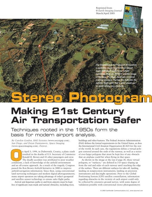
The International Air Transport Association<br />
is updating major international airport<br />
maps that don’t conform to current<br />
standards. Here an IKONOS satellite image<br />
of Madeira, Portugal, illustrates a typical<br />
training scenario. The red line indicates the<br />
optimal flight path that a pilot would use<br />
to avoid hitting any obstacles.<br />
Stereo Photogram<br />
Making 21st Century<br />
Air Transportation Safer<br />
Techniques rooted in the 1950s form the<br />
basis for modern airport analysis.<br />
By Carolyn Gordon, <strong>BAE</strong> <strong>Systems</strong> (www.socetgxp.com),<br />
San Diego, and Dejan Damjanovic, Space Imaging<br />
(www.spaceimaging.com), Denver.<br />
On April 3, 1996, in Dubrovnik, Croatia, a plane crash<br />
resulted in the deaths of U.S. Secretary of Commerce<br />
Ronald H. Brown and 33 other passengers and crew.<br />
The deadly accident was attributed to poor weather<br />
conditions, a lack of knowledge of the airfield environment<br />
and an off-course approach. As a result of the tragedy, Congress<br />
passed the Ron Brown Airfield Initiative in 2000 to improve<br />
airfield navigation information. Since then, using conventional<br />
land surveying techniques and modern digital <strong>photogrammetry</strong>,<br />
many airport operators are taking advantage of today’s geospatial<br />
and satellite sensor technology to ensure safer flight paths.<br />
Arrival and departure paths to and from airports must be kept<br />
free of significant man-made and natural obstacles, including trees,<br />
buildings and other features. The Federal Aviation Administration<br />
(FAA) defines the formal requirements in the United States, as does<br />
the International Civil Aviation Organization (ICAO) for the rest<br />
of the world. In each case, the regulations define a virtual polygon<br />
centered around the ends of the runway, as well as a series<br />
of ever-larger polygons that must be kept free of any obstacle<br />
that an airplane could hit when flying in that space.<br />
As shown in the image at the top of page 38, these virtual<br />
polygons, or “surfaces,” are defined in 3-D space sloping up<br />
from the end and sides of each runway until reaching the edge<br />
of the surface. There are different surfaces for take-off, landing,<br />
landing on nonprecision instruments, landing on precision<br />
instruments and day/night operations. Prior to the Global<br />
Positioning System (GPS) satellite constellation, information<br />
regarding obstacles in the vicinity of each airport could only<br />
be collected by extensive ground survey, with some degree of<br />
validation possible with conventional <strong>stereo</strong> <strong>photogrammetry</strong>.<br />
© 2005 Earthwide Communications LLC, www.eijournal.com